1
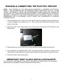
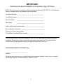
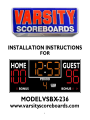
1
INSTALLATION INSTRUCTIONS
MODEL VSBX-236 LED
3’ X 8’ INDOOR SCOREBOARD
NOTE TO INSTALLERS:
PLEASE RETURN THIS MANUAL TO THE INDIVIDUAL IN CHARGE OF THE
SCOREBOARD UPON COMPLETION OF INSTALLATION.
The scoreboard and all accompanying accessories have been carefully inspected and tested before leaving the factory.
However, it is possible for damage to have occurred during shipping. Therefore, we ask that you inspect all shipping
containers upon arrival for damage and ensure that you have all of the parts listed below. If you find that damage has
occurred during shipping: DO NOT refuse the shipment, follow the instructions for filing a freight damage claim
found below, and notify the manufacturer immediately.
THE SCOREBOARD SYSTEM SHOULD INCLUDE THE FOLLOWING PARTS:
ITEMS IN LARGE PACKAGE
(1) 3’ x 8’ scoreboard; shipped in one (1) section
ITEMS IN ACCESSORY BAG
(1) Keyboard controller with keypad inserts
(1) 12-volt DC wall transformer
(1) CD ROM (including installation, operation, maintenance, warranty, and support information)
Cable-controlled systems (standard):
(1) Junction box cover with built-in 5-pin din socket
(1) 20-ft. din cable with male 5-pin plugs
(1) 150' roll of control cable or longer if customer specified
For wireless systems (Optional):
(1) Wireless transmitter with interface cable
(1) Keyboard mounting bracket for transmitter
Optional parts:
(1) 21”x8' sponsor panel(s) shipped in one (1) section
(3) Mounting brackets for sponsor panel and accompanying hardware
(1) Internal Battery Pack for LCD Keyboard Controller
NOTE: INSTALLATION HARDWARE NOT SUPPLIED. CHECK LOCAL CODE FOR REQUIREMENTS. ANCHORS,
BOLTS, CHAINS, CABLES AND RELATED HARDWARE MUST MEET MINIMUM WEIGHT REQUIREMENTS.
INSTRUCTIONS FOR REPORTING SHIPPING DAMAGE
Shipping damage must be noted at the time of delivery. Consignee must note on the “Delivery Receipt” form
DAMAGED. Please make notations of the type of damage to the freight and to the packaging. Ask the delivery driver to
call the local terminal and report immediately. The shipper is not responsible for the shipments that are not signed for as
damaged upon arrival. Please contact the manufacturer immediately to report. The shipper is responsible for filing the
rd
claim, unless shipped 3 party.
If damage is discovered after delivery, call the delivery company to report the concealed damage and please call the
manufacturer immediately to report. Concealed damage must be reported within 5 days after the delivery date. If the
damages are found after this time, the manufacturer will not be responsible.
2
INSTALLATION OVERVIEW
This manual will walk you through the installation of the scoreboard. While care has been taken
to consider the many scenarios for installation, some general information applies to all. Use this
guide as closely as possible to ensure proper installation, as follows:
Review the product specifications below to determine your specific installation hardware.
Mount the scoreboard to the wall or suspend it from a ceiling structure.
Install the electrical service for the scoreboard and the controller.
Install the control cable for cable-controlled systems. No additional installation is
necessary for Wireless Remote Control systems.
Install any options, such as sponsor panels or protective nets, according to the installation
instructions included with each option package.
Test the installed system.
PRODUCT SPECIFICATIONS
Overall Dimensions:
3’-0” tall x 8’-0” long x 8” deep, shipped in one (1) section
Weight:
Hanging weight
Approx. 135 lbs.
Shipping weight
Approx. 190 lbs.
Power Requirements:
Scoreboard:
1 - 120-volt, 20-amp, 60 Hz grounded AC circuit. Ideally, this will be a dedicated circuit.
Access must be provided to turn off the power to the scoreboard after each use. Failure
to turn off the power to the scoreboard could affect the functionality of the scoreboard;
such as from a power surge or lightning strike.
It is important to utilize the equipment ground inside the scoreboard cabinet at the utility
box provided for the AC power connection.
Keyboard controller:
1 - 120-volt, 15-amp, 60 Hz grounded AC circuit - standard wall receptacle.
Communication Cable Requirements (for cable-controlled systems only):
Four conductor cable – 28 gauge, twisted pair (two pairs), shielded data cable.
3
MOUNTING THE SCOREBOARD TO A WALL
NOTE: Use hardware appropriate for the wall type you are mounting to and capable of
supporting the weight of the scoreboard. No mounting brackets are necessary as the predrilled mounting flanges on the top and bottom of the scoreboard are provided to mount the
scoreboard directly to the wall. The scoreboard must be attached to the wall securely
through all four (4) mounting holes in the top and bottom mounting flanges. (See the figure
below for location of mounting holes and mounting flanges.)
Remove the scoreboard from its packaging, making sure not to pry against or cut into
the scoreboard. Inspect the unit for shipping damage according to the instructions on
page 1.
Connect a lift device to the two hanging brackets on the top of the scoreboard and lift
the scoreboard into place. Cardboard or foam packaging can be used as a pad
between the lift and scoreboard to protect the face of the scoreboard. Remove the
antenna from the scoreboard if your system is wireless. (See the figure below for
location of hanging brackets.)
Lift the scoreboard to the desired location and mark the holes in the top and bottom
flanges. It may be necessary to mark the top flange, install anchors, and secure the top
of the scoreboard before having access to the bottom flange. Ensure that you use all
four mounting holes in the top and bottom flanges.
Replace the antenna if your system is wireless.
HANGING THE SCOREBOARD FROM THE CEILING
1. Remove the scoreboard from its packaging, making sure not to pry against or cut into the
scoreboard. Inspect the unit for shipping damage according to the instructions on page 1.
NOTE: CARE MUST BE TAKEN NOT TO DAMAGE THE SCOREBOARD WHILE LIFTING IT INTO PLACE. IF THE
SCOREBOARD WILL BE “AGAINST” THE LIFTING DEVICE, PLACE CARDBOARD OR PACKING FOAM
BETWEEN THE LIFT AND THE SCOREBOARD BEFORE LIFTING. ALSO, IF THE SCOREBOARD HAS WIRELESS
4
COMMUNICATION, REMOVE THE ANTENNA FROM THE FRONT OF THE SCOREBOARD BEFORE LIFTING TO
PREVENT DAMAGE. TAKE CARE TO REPLACE THE ANTENNA WHEN THE INSTALLATION IS COMPLETE.
2. If eye bolts, cables or chains are to be used to suspend the scoreboard, ensure that they are
capable of supporting the weight of the scoreboard. Choose one of the following methods to get
the scoreboard into place:
Connect the cables or chains you will use to suspend the scoreboard to the hanging
brackets on top of the scoreboard cabinet using “C” clips or clevises. Connect the strap,
cable, or chain you will use to lift the scoreboard to the two outside mounting holes in the
top rear flange.
OR:
Connect the cables or chains you will use to suspend the scoreboard to the hanging
brackets on top of the scoreboard cabinet using “C” clips or clevises. Connect the strap,
cable, or chain you will use to lift the scoreboard to the same “C” clips or clevises.
3. If the scoreboard will be against the lift during lifting, place cardboard or foam between the lift and
scoreboard to protect the face of the scoreboard, and remove the antenna from the face of the
scoreboard if your system is wireless.
4. Lift the scoreboard into place. Check clearance during lift. Connect the suspension system and
lower the scoreboard until its weight is on the suspension system and disconnect the lifting cables
from the scoreboard.
5. Place a level in the top channel of the scoreboard cabinet to see if adjustments need to be made.
6. Replace the antenna if your system is wireless.
NOTE: It is recommended that the cables that will be used to permanently suspend the
scoreboard be attached to the ceiling structure first, then to the scoreboard’s hanging
brackets after it is lifted into position using a lifting device.
(See illustration on Page 4 for location of hanging brackets.)
RUNNING & CONNECTING THE CONTROL CABLE
(For scoreboards with Wireless Remote Control, skip this step.)
The control cable must be run in a separate conduit than is used for the electrical service. The
control cable should run from the scoreboard to a location that is within 10 feet of the scorekeeper’s
location and into a 2”X4” wall box.
NOTE: IF THE WIRES IN YOUR CABLE DO NOT COLOR MATCH WHAT IS SHOWN, CONNECT
TO THE TERMINALS WITH THE BLACK, GREEN, AND WHITE CONDUCTORS. DO NOT
CONNECT A WIRE TO THE RED TERMINAL. MATCH THE SAME COLORS IN YOUR CABLE
TO THE BLACK, GREEN, AND WHITE WIRES ON THE BACK OF THE WALL PLATE AT THE
SCORING LOCATION.
5
At the scorekeeper’s location:
1. With the communication cable installed between the scoreboard and the 2”X4” wall box, locate
the wall plate provided with your installation hardware.
2. The back of the wall plate has a label indicating how the connections are to be made. Likely,
the insulation will not be the same color on the wires in the cable as that on the wires on the
back of the wall plate. Follow the chart if possible, but more importantly; whatever the matchup is at the wall plate should also be the match-up at the scoreboard.
3. Secure the junction box cover to the installed junction box.
At the scoreboard:
Open the module access door (HOME score display) by removing the screws securing it.
1. Inside the scoreboard, connect the control cable leads to the appropriate terminals on the
terminal block, according to the label above the terminal block.
3. Close and secure the module access door.
6
RUNNING & CONNECTING THE ELECTRIC SERVICE
NOTE: THIS PORTION OF THE INSTALLATION REQUIRES A LISCENSED ELECTRICIAN.
IDEALLY, THE SCOREBOARD WILL BE POWERED FROM A DEDICATED 120-VOLT / 20 AMP
CIRCUIT. ADDITIONALLY, SINCE THE SCOREBOARD’S POWER SHOULD BE TURNED OFF
AFTER EACH USE, THERE SHOULD BE EASY ACCESS TO THE POWER SWITCH OR CIRCUIT
BREAKER. IF ACCESS TO THE CIRCUIT BREAKER IS NOT AN OPTION, INSTALL A SWITCH
SOMEWHERE THAT IS ACCESSIBLE, EVEN IF UNDER THE SCOREBOARD AT AN ABOVE
AVERAGE HEIGHT.
1. The scoreboard has a ½” knock-out on the top left corner for bringing in the electrical service.
It can be enlarged if the conduit size is ¾”. This is where the conduit from the power source
needs to terminate.
2. Open the “Home” score, which serves as an access panel and locate the 2”X4” utility box, see
image below.
3. Remove the cover on the utility box and route the power supply wiring to the utility box.
4. The connections are standard black, white, and green (ground). Included is a utility ground
which must be used. Make up the power supply connections and replace the utility box cover.
5. Close the “Home” score access panel.
IMPORTANT SHOT CLOCK INSTALLATION NOTE!
For instructions on the installation of shot clocks, including how to connect them to the scoreboard,
please refer to the installation manual included with the shot clocks.
7
TESTING THE INSTALLED SYSTEM
NOTE: Please refer to the OPERATORS MANUAL on the CD, or included with the system to
operate the scoreboard.
AT START-UP: When the scoreboard is initially powered up, it should display “zeros” in the
Home and Guest scores and a “one” in the Period for at least 45 seconds. If the controller has
not been turned on and either RESET or ENTER has not been pressed within that time period,
the scoreboard may revert to a “power saving” mode, where the Period continually flashes an
“8”. This is normal and should change to the start-up values at the time either the RESET or
ENTER keys have been pressed. Follow the instructions below to verify the operation of the
scoreboard.
Testing the scoreboard system:
Turn the power to the scoreboard ON using the power disconnect switch or circuit breaker.
If your scoreboard is a cable system, verify that all cable connections are properly terminated
and that the 20’ supplied cable is properly connected on both the back of the controller and at
the junction box.
If your scoreboard is a wireless system, verify that the radio transmitter interface cable is
connected to both the transmitter and also one of the DIN sockets on the back of the
controller.
The HOME and GUEST scores should display a “0” and the PERIOD should show a “1”.
Use the controller keys to verify that all sections of the scoreboard respond properly.
Example: Add scores to both teams, increase the PERIOD, use the BONUS keys.
If the scoreboard displays a flashing “8” in the PERIOD position, this is either an indication of
no signal communication between the scoreboard and controller, or simply an extended period
of inactivity with the controller. The timeout period is one hour. If the time is less than that,
check all communication cable connections and press RESET on the controller. If the flashing
“8’ remains, contact Technical Support.
NOTE: Always turn both the controller and the scoreboard OFF after each use. If the
controller is turned OFF but the scoreboard remains ON, (or if the controller loses
communication with the scoreboard), the scoreboard’s INNING digit will begin to flash with
the rest of the displays blank. This feature is intended to remind the user to turn power to
the scoreboard OFF after each use.
NOTE: To activate your warranty, your check off sheet must be signed and returned/faxed to
Sportable Scoreboards Inc. A copy of this sheet should be placed with your
Installation/Operators Manual in the event technical support is needed. Fax number (270) 7533773.
8
IMPORTANT!
Warranty Activation/Installation & Completion Sign Off Sheet
NOTE: This sheet must be completely filled out and returned/faxed (270) 753-3773 to Scoreboard
Service Company before your warranty can be activated.
Your Serial Number _______________________________________
Your Model Number _______________________________________
Date Purchased
_______________________________________
Sales Agent
_______________________________________
Person Authorizing Purchase (title) ____________________________
Date Installation Completed _________________________________
Company or Person Responsible
For Installation (address/phone number) ________________________
This document confirms that the installation for the 3-ft.x 8-ft. Basketball Scoreboard has been
completed. All structural, wiring, and power requirements have been met. This unit has been
tested in scoring and diagnostic modes, ensuring the functionally of the unit.
________________________________
Scoring/timing equipment responsible party
________________________________
Installer
So that we may better serve you, please have this information available in the event you need to
call technical support. Technical Support: 1-800-411-3136
9