1
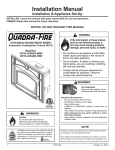
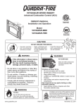
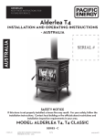
R
VOYAGEUR GRAND INSERT
Automatic Combustion Control (ACC)
OWNER’S MANUAL
Installation and Operations
Model:
GRAND-MBK-AU
INSTALLATIONS TO COMPLY WITH AS/NZS2918:2001
AND WILL REQUIRE A BUILDING CONSENT
IMPORTANT: Read all instructions carefully before starting installation. Failure to follow these
instructions may result in a fire hazard and will void the warranty.
• Fig. 3,4,5,6, 7 and Table 1,2,3,4 relate to installations with tested flue systems; as per AS/NZS
2918:2001 - Appendix F, with a ceiling angle between 0° - 30° inclusive.
• For installations with a ceiling angle greater than 30°, refer to Fig. 18.1, 21.1 & 21.2 and AS/NZS
2918:2001 4.6.3(b)
• Ceiling Plate may vary in size depending on ceiling angle. Please specify ceiling pitch prior to
ordering the ceiling plate.
• Quadra-Fire Voyageur Grand ACC wood burner’s are tested and approved to the N.Z. National
Environmental Standards;
GRAND-MBK-AU Voyageur Grand Insert Hardwood Certified
Particulate Emissions = 2.0 g/kg Space Heating Efficiency = 62.8%
Page 1
7075-205
April 29, 2013
R
Voyageur Grand
Hearth & Home Technologies welcomes you to our tradition
of excellence! In choosing a Quadra-Fire appliance, you
have our assurance of commitment to quality, durability, and
performance.
This commitment begins with our research of the market,
including ‘Voice of the Customer’ contacts, ensuring we
make products that will satisfy your needs. Our Research
and Development facility then employs the world’s most
advanced technology to achieve the optimum operation of
our stoves, inserts and fireplaces. And yet we are old-fashioned when it comes to craftsmanship. Each unit is meticulously fabricated and surfaces are hand-finished for lasting
beauty and enjoyment. Our pledge to quality is completed
as each model undergoes a quality control inspection.
We wish you and your family many years of enjoyment in
the warmth and comfort of your hearth appliance. Thank
you for choosing Quadra-Fire.
VOYAGEUR GRAND
OVERALL AVERAGE EFFICIENCY BURNING HARDWOOD
(WHEN TESTED IN ACCORDANCE TO AS/NZS 4012)
62.8%
AVERAGE PARTICULATE EMISSION FACTOR BURNING HARDWOOD
(WHEN TESTED IN ACCORDANCE TO AS/NZS 4013)
2.0 g/kg
MAXIMUM AVERAGE HEAT OUTPUT BURNING
HARDWOOD
9.3 kw
APPROVED FUEL
BURN ONLY HARDWOOD WITH A MOISTURE CONTENT LESS THAN 25% (dry basis).
WETBACK - ALL MODELS
MANUFACTURED BY
Wetbacks are NOT an approved option and must
not be fitted.
NOTE: Performance may vary from test values
depending on actual operating conditions.
INSTALLATION DATE
R
VOYAGEUR GRAND INSERT
This appliance has been TESTED TO AS/NZS4013 for
Hardwood by VIPAC LTD.
Report # 30A-13-0025-TRP-331382-0
Date tested: March 2013
Serial No.
007057
Mfg by:
1445 N. Highway, Colville, WA 99114
www.quadrafire.com
U.S. ENVIRONMENTAL PROTECTION AGENCY - Export stove. May not be operated within the United States
JAN FEB MAR APR MAY JUN JUL AUG SEP OCT NOV DEC
2013 2014 2015
DO NOT REMOVE THIS LABEL
Made in U.S.A. of US and
imported parts.
7075-206
Page 2
7075-205
April 29, 2013
Voyageur Grand
R
Safety Alert Key:
• DANGER! Indicates a hazardous situation which, if not avoided will result in death or serious injury.
• WARNING! Indicates a hazardous situation which, if not avoided may result in death or serious injury.
• CAUTION! Indicates a hazardous situation which, if not avoided, may result in minor or moderate injury.
• NOTICE: Indicates practices which may cause damage to the appliance or to property.
TABLE OF CONTENTS
Congratulations................................................................2
Serial Number Label.........................................................2
User’s Guide
Section 1: Operating Instructions
A.
Quick Start Guide...............................................4
B. Automatic Combustion Control (ACC)...............5
C. Air Controls........................................................5
D. Burn Rates and Operating Efficiency.................5
E. Blower Control Box Snap Disc Operations........5
F. Blower Operating Instructions............................5
Section 2: Maintenance & Service
A.
Disposal of Ashes..............................................7
B.
Chimney and Chimney Connector
Inspection/Cleaning...........................................7
C. Appliance Inspection - Routine..........................7
D. Cleaning Plated Services...................................7
E. Glass Cleaning...................................................8
F.Inspect Firebrick & Replacement Instructions....8
G. Quick Reference Maitenance Guide..................9
H. Trouble Shoot Guide..........................................10
Section 3: Service Parts Replacement
A.
B.
C.
D.
E.
F.
G.
Glass Replacement............................................11
Snap Disc Replacement....................................11
Wiring Diagram..................................................11
Blower Replacement..........................................12
Door Handle Assembly......................................13
Baffle & Ceramic Blanket Removal....................13
Tube Channel Assembly Replacement..............14
Installer’s Guide
Section 4: Getting Started
A.
B.
C.
Tools and Supplies Needed...............................15
Fire Safety..........................................................15
Inspect Appliance and Components
and Pre-Burn Checklist......................................15
Section 5: Dimensions and Clearances
A. Appliance Dimensions.......................................16
B. Clearances to Combustibles (UL and ULC)
and Hearth Protection Requirements.................17
C. Alternate Floor Protection Calculation...............18
Section 6: Chimney Systems
A.
B.
C.
D.
E.
F.
G.
Venting Systems................................................19
Inspections.........................................................19
Larger Chimneys................................................19
Masonry Chimney..............................................19
Prefabricated Metal Chimney.............................19
Installation into a Masonry Fireplace.................20
Installation into a Factory Built Fireplace...........20
Section 7: Appliance Set-up
A.
B.
C.
D.
E.
F.
G.
H.
I.
Outside Air Installation.......................................22
Optional Elbow Flue Adapter Installation...........23
Securing Stove Pipe/Liner to Flue Collar...........23
Leveling Legs.....................................................23
Securing Appliance to Stove Pipe/Liner.............24
Standard Surround & Trim Installation...............24
Standard Surround & Cast Trim,........................25
All Cast Surround...............................................26
Blower Cord Installation - Left Side....................26
Section 8: Reference Materials
A.Warnings............................................................29
B. Warranty Policy..................................................30
C. Contact Information............................................32
April 29, 2013
7075-205
Page 3
R
Voyageur Grand
User’s Guide
1
Operating Instructions
A. Quick Start Guide
Note: These are generic drawings and may not represent
your specific model.
FIRST FIRE ITEMS NEEDED:
LOW
START-UP
AIR
ADD NEWSPAPER
LOAD WOOD
OPEN AIR
CONTROLS
HIGH
10 Pieces of Newspaper, 10-20 Pieces of Dry Kindling
and a Few Pieces of Dry Split Wood.
BURN
RATE
Upper
right
corner
Lower
right
corner
Push In and then Pull Out
2
1
ADD KINDLING
3
WARNING! Risk Of Fire
DO NOT LEAVE UNATTENDED
During startup, if additional draft is needed,
allow the door to remain open approximately1/2 inch. Once the draft is established,
close and securely latch the door to prevent:
• Spillage of smoke, flame and carbon
monoxide
• Spillage of sparks, coals and logs
• Over-firing
LIGHT THE PAPER
DO NOT leave the stove unattended with the door open
4
ADD MORE WOOD &
SECURELY LATCH THE DOOR
5
REDUCE AIR
CONTROL
Set to desired heat
output
HIGH
LOW
The stove is ready for
normal operation.
BURN RATE CONTROL
Upper Right Corner
6
Page 4
7
7075-205
April 29, 2013
Voyageur Grand
R
B. Automatic Combustion Control (ACC)
Typically, when you build a fire, you open the air controls fully
and monitor the fire to prevent it from going into an overfire
situation and/or burning your wood up too quickly before you
shut down the air controls to the desired burn rate.
When using the Automatic Combustion Control (ACC) system,
you do not have to continually monitor the fire. Once you
set the ACC system it will control the fire for you. Follow the
instructions below to learn how to operate your stove with
ease.
C. Air Controls
D. Burn Rates and Operating Efficiency
For maximum operating efficiency
1. Burn dry, well-seasoned wood.
2. Follow these burn rate instructions below and refer to
Figure 5.1.
*NOTE: These are guidelines. Actual settings may vary with
type of wood, chimney draft, altitude and other variables.
E. Blower Control Box & Snap Disc
Operating Instructions
1. The blower will turn on/off automatically when set to
AUTO. Figure 6.1 on page 6.
1. Start-Up Air Control
The function of the Start-Up Air Control is to activate the
Automatic Combustion Control system (ACC).
• Push the Start-Up Air Control all the way back until it stops
and then pull forward to the front of the appliance until it
stops. Figure 5.1.
• The air channel opens and allows air to enter the front of
the appliance for approximately 20-25 minutes.
• The air channel gradually shuts down until it is completely
closed at the end of the 20-25 minutes.
• The fire is now controlled by the air supplied by the Burn
Rate Air Control. Figure 5.1.
• This function should be performed each time you reload
the appliance.
2. Burn Rate Air Control
• The air supply enters at the upper front of the firebox,
near the top of the glass door.
• This preheated air supplies the necessary fresh oxygen
to mix with the unburned gases, helping to create the
second, third and fourth combustion process.
• This air is regulated by the Burn Rate Air Control.
• There are four settings High, Medium-High, Medium-Low
and Low.
• When the control is raised all the way up it is on the High
setting and when pushed all the down it is on the Low
setting.
HIGH
Burn Rate Control
LOW
2. When set to MANUAL, the fan will turn on/off only when
you turn it on or off. This setting over-rides the internal
snap disc.
3. Swing the grille downward to expose the blower controls.
Adjust the speed of the fan by turning the HIGH/LOW
knob to the desired setting.
F. Blower Operating Instructions
1.Initial (cold) startup: Open both controls fully by raising
the Burn Rate Air Control all the way up until it stops and
PUSH the Start-up Air Control back until it stops. The
blower tends to cool the appliance. Leave the blower off
until the burn is well established, i.e., 30 minutes.
2.High Burn Setting: Both controls are open. Burn Rate
Air Control is pulled up and the Start-up Air Control is fully
pushed in. Blower may remain on.
3. Medium-High Burn Setting*: Burn Rate Air Control
is closed then opened to 1 inch to fully open (pull up).
Blower may remain on.
4. Medium-Low Burn Setting*: Burn Rate Air Control
is closed then opened to 1/4 inch to 1/2 inch (pull up).
Leave the blower off until the burn is well established, i.e.,
30 minutes.
5. Low Burn Setting*: Burn Rate Air Control is closed
(down position). Leave the blower off until the burn is well
established, i.e., 30 minutes.
*NOTE: For burn settings 3 to 5 the Start-up Air Control
needs to be pushed in (Open) then pulled forward to activate the Automatic Combustion Control (ACC).
NOTE: For maximum efficiency and lowest emissions,
when operating the blower in either the automatic or
manual setting for the low and medium low burn settings
leave the blower off until the burn is well established, i.e.,
30 minutes.
ACC Start-up
Air Control
To activate: Push back until it stops
and then pull forward until it stops
Figure 5.1 Start-up and Burn Rate Air Controls
April 29, 2013
7075-205
Page 5
R
Voyageur Grand
6. The blower is equipped with a rheostat (speed control).
The highest blower speed is obtained by turning the
rheostat on, then adjusting back towards “OFF” as far as
possible without turning the blower off. For a low blower
speed, turn the control knob clockwise as far as possible
Blower Controls Under Ash Lip
MANUAL: overrides the internal
snap disc
AUTO: Fan with turn ON/OFF
automatically and is controlled
by the internal Snap Disc
Figure 15.1
6.1
NOTICE!
Do NOT operate a circulating fan within close proximity, approximately 4 ft (1.2m), of appliance
•Can reverse air flow, blowing hot air into appliance
cavity.
•Can damage appliance blower due to overheating.
Page 6
7075-205
April 29, 2013
Voyageur Grand
R
2
Maitenance & Service A. Disposal of Ashes
• Frequency: When ash reaches the top of the brick
covers (should not spill over covers). Leave 1/4 inch
(6mm) of ash in the bottom of the firebox.
• By: Homeowner
WARNING! Risk of Fire! Ashes could contain hot embers.
• Place ashes in a metal container with a tight-fitting lid.
• The closed container should be placed on a noncombustible
floor or on the ground, well away from all combustible
materials, pending final disposal.
• If the ashes are disposed of by burial in soil or otherwise
locally dispersed, they should be retained in the closed
container until all cinders have thoroughly cooled
• The creosote vapors condense in the relatively cool
chimney flue of a slow-burning fire.
• As a result, creosote residue accumulates on the flue
lining. When ignited this creosote makes an extremely
hot fire.
• The chimney and chimney connector shall be inspected
every two months during the heating season to
determine when a creosote buildup has occurred.
• When creosote has accumulated it shall be removed to
reduce the risk of a chimney fire.
C. Appliance Inspection - Routine
B. Chimney and Chimney Connector
Inspection/Cleaning
• Frequency: Every 2 months during heating season or
as recommended by a certified chimney sweep; more
frequently if chimney exceeds or is under 14-16 feet (4.3
to 4.8m) measured from bottom of appliance.
• By: Certified chimney sweep
• Remove all ash from the firebox and extinguish all hot
embers before disposal.
• Allow the appliance to cool completely.
• If your type of installation involves a full reline of the
chimney, it will be necessary to either remove the baffle
from the insert, or remove the insert from the fireplace
and disconnect the vent prior to cleaning the chimney.
Refer to page 23 in this manual for instructions on Baffle
Removal.
• If your type of installation is direct connect within a masonry
chimney, the insert will need to be pulled out from the
fireplace and disconnected from the flue prior to cleaning
the chimney.
• The creosote or soot should be removed with a brush
specifically designed for the type of chimney in use.
• Clean out fallen ashes from the firebox.
• It is also recommended that before each heating season
the entire system be professionally inspected, cleaned
and repaired if necessary.
• Frequency: Every 2 months at the same time the
chimney and chimney connector are inspected.
• By: Homeowner
Check for:
• Cracks in glass
• Door handle - smooth cam operation
• Baffle and ceramic blanket correct placement
• Baffle for warpage
• Firebrick for cracks, broken or crumbly
• Door gasket. (Dollar bill test). Place a dollar bill between the stove and the door and then shut the door. If
you can pull the dollar bill out, replace the door gasket.
• Glass frame for loose screws
D. Cleaning Plated Surfaces
• Frequency: As desired
• By: Homeowner
• Clean all the fingerprints and oils from plated surfaces
BEFORE firing the appliance for the first time.
• If not cleaned properly before lighting your first fire, the
oils can cause permanent markings on the plating.
• After the plating is cured, the oils will not affect the finish
and little maintenance is required.
• Wipe clean as needed.
WARNING! Risk of Fire!
Do not use chimney cleaners or flame colorants in your
appliance. It will corrode your pipe.
April 29, 2013
Creosote - Formation and Need for Removal
• When wood is burned slowly, it produces tar and other
organic vapors, which combine with expelled moisture
to form creosote.
CAUTION! Do not use polishes with abrasives. It will
scratch plated surfaces.
7075-205
Page 7
R
Voyageur Grand
F. Inspect Firebrick & Replacement
Instructions
E. Glass Cleaning
• Frequency: As desired
• Frequency: After each ash removal
• By: Homeowner
• Clean glass with a non-abrasive glass cleaner. Abrasive
cleaners may scratch and cause glass to crack.
• By: Homeowner
• If the deposits on the glass are not very heavy, normal
glass cleaners work well. Heavier deposits may be
removed by using a damp cloth dipped in wood ashes or
by using a commercially available oven cleaner.
• After using an oven cleaner, it is advisable to remove any
residue with a glass cleaner or soap and water. Oven
cleaner left on during the next firing can permanently stain
the glass and damage the finish on plated metal surfaces.
• A portion of the combustion air entering the firebox is deflected down over the inside of the door glass.
• This air flow “washes” the glass, helping to keep smoke
from adhering to its surface.
• When operated at a low burn rate, less air will be flowing
over the glass and the smoky, relatively cool condition of
a low fire will cause the glass to become coated.
• Operating the appliance with the Burn Rate Air Control
and Start-Up Air Control all the way open for 15-20 minutes should remove the built up coating.
CAUTION! Handle glass assembly with care. Glass is
breakable.
Replace the firebrick if they become crumbly and/or if
there is a 1/4 inch (6.35mm) gap between the bricks.
The firebox is lined with firebrick, which has exceptional
insulating properties. Do not use a grate; simply build
a fire on the firebox floor. Do not operate appliance
without firebrick.
1. After the coals have completely cooled, remove all
old brick and ash from unit and vacuum firebox.
2. Remove new brick set from box and lay out to the
diagram shown in the instructions that come with
the replacement brick set.
3. Lay bottom bricks in unit.
4. Install rear bricks on the top of the bottom bricks.
5. Install side bricks. Slide top of brick under clips
on side of firebox and push the bottom of the brick
until it is flush with the side of the unit.
Use Part 832-0550 when ordering individual brick. Provide
brick dimension or copy the page in the service parts list, mark
the desired brick and take it to your authorized dealer.
• Avoid striking, scratching or slamming glass
• Avoid abrasive cleaners
• Do not clean glass while it is hot
Page 8
7075-205
April 29, 2013
Voyageur Grand
R
G. Quick Reference Maintenance Guide
CAUTION! Allow the appliance to completely cool
down before performing any cleaning or maintenance.
Baffle & Blanket
Blanket
Baffle
Optional Blower
Chimney System
Frequency
Start the first inspection after the first 2 months of use,
or if performance changes, and adjust your schedule
accordingly. Maintenance is required for safe operation
and must be performed to maintain your warranty.
Task
MONTHLY
or
After Every
Cord of Wood
Baffle and blanket placement is critical to
heat output, efficiency and overall life of the
unit. Make sure the baffle is pushed all of the
way to the back of the firebox and the blanket
is laying flat. Inspect baffle for cracks.
YEARLY
or
After Every
4 Cords of
Wood
Vacuum the blower impellers.
EVERY 2
MONTHS
or
After Every
4 Cords of
Wood
The chimney and chimney cap must be inspected for soot and creosote every two
months during the burn season or more frequency if chimney exceeds or is under 14-16 ft
(4.3m-4.8m) measured from bottom of appliance.
This will prevent pipe blockage, poor draft,
and chimney fires.
Always burn dry wood to help prevent cap
blockage and creosote build-up.
Firebrick & Ash Removal
Door & Glass Assemblies
Door Handle
Latch Cam
Spacing Washers
WEEKLY
or
After Every
25 Loads of
Wood
WEEKLY
or
After Every
25 Loads of
Wood
WEEKLY
or
After Every 25
Loads of Wood
Ashes must be cool before you can dispose
of the ashes in a non-combustible container.
Firebrick is designed to protect your firebox.
After ashes are removed, inspect the firebrick and replace firebricks that are crumbling, cracked or broken.
Keep door and glass gasket in good shape to
maintain good burn times on a low burn setting.
To test: place a dollar bill between the stove
and door and then shut the door. If you can
pull the dollar out, remove one washer from
door handle behind latch cam and try again. If
you can still pull it out, replace the door gasket.
Check the glass frame for loose screws to
prevent air leakage. Check glass for cracks.
Check the door latch for proper adjustment.
This is very important especially after the door
rope has formed to the stove face.
Check door handle for smooth cam operation.
Note: These are generic drawings and may not represent your specific model.
April 29, 2013
7075-205
Page 9
R
Voyageur Grand
H. Troubleshooting Guide
With proper installation, operation, and maintenance your woodstove will provide years of trouble-free service. If you do
experience a problem, this troubleshooting guide will assist you or a qualified service person in the diagnosis of a problem
and the corrective action to be taken.
Start Fire Problems
Possible Cause
Solution
Can not get fire started
Excessive smoke or spillage
Burns too slowly
Not enough heat output
Not enough kindling/paper or no
kindling/paper
Use dry kindling, more paper. Arrange kindling &
wood for air movement.
Check for restricted termination cap
Check for blockage of outside air kit (if installed).
Check for flue blockage.
Not enough air for fire to ignite
Pre-warm flue before starting fire (refer to Building
a Fire Section).
Check for adequate vent height (refer to Chimney
Height Section).
Open window below the appliance towards the
wind.
Wood condition is too wet, too
large
Use dry, seasoned wood (refer to Seasoned Wood
Section).
Bed of coals not established
before adding wood
Start with paper & kindling to establish bed of
coals (refer to Building a Fire Section).
Flue blockage such as birds’
nests or leaves in termination
cap
Have chimney inspected for creosote and cleaned
by a certified chimney sweep.
Down draft or negative pressure
Competition with exhaust
devices
Do not use exhaust fans during start-up (refer to
Negative Pressure Section).
Fire burns too fast
Mix in hardwood.
Extremely dry or soft wood
Mix in less seasoned wood after fire is established
(refer to Wood Fuel Section).
Check for correct vent height; too much vertical
height creates overdrafting.
Overdrafting
Page 10
Open window below the appliance towards the
wind.
Check location of vent termination (refer to
Chimney Termination Requirement Section).
7075-205
April 29, 2013
Voyageur Grand
R
3
Service Parts Replacement
UNPLUG APPLICE FROM ANY POWER SOURCE
BEFORE REPLACING ANY COMPONENTS
A. Glass Replacement
(Replace with 5mm ceramic glass only)
1. Ensure that the fire is out and the appliance is cool to
the touch.
2. Protect a table or counter top with padding or towels.
Protect your hands and wear gloves to prevent injury.
3. Remove the door with the broken glass by lifting the
door up and off of the hinges.
4. Lay door face down on a table or counter making sure
the handle hangs over the edge so the door lays flat, on
a soft surface.
5. Remove the screws from each glass retainer and remove
the glass. (If screws are difficult to remove, soak with
penetrating oil first).
B. Snap Disc Replacement (Cont’d)
2. Remove the 2 screws from the blower access assembly
and slide assembly away from the appliance
3. Locate the snap disc bracket assembly behind the blower
controls on the right side under the ash lip. Figure 8.1
4. Remove the 2 mounting screws in the blower control
bracket and slide assembly towards you.
5. Using a Phillips head screw driver, remove the 2 screws
from the snap disc and lift the snap disc off of the mounting
bracket. Disconect the wires and replace with new snap
disc and re-connect the wires.
6. Slide the blower control bracket back into position and
secure with the 2 mounting screws.
6. Center the glass with edges evenly overlapping the
opening in the door, (i.e. same space top and bottom,
left and right sides).
7. Replace the glass retainers. Be careful not to cross
thread the screws.
Blower Controls & Snap
Disc Under Ash Lip
8. Tighten each retainer just a few turns until each is
secured. Check again for centering of glass in door
frame. Continue to tighten each retainer alternately, a
few turns at a time, until the glass is secure. DO NOT
OVERTIGHTEN - can cause glass to break.
Snap Disc
9. Replace the door on the appliance.
WARNING! Risk of Fire or Injury!
Use only glass that is specified in the manual, DO NOT
replace with any other material. Glass breakage will occur.
Figure 7.1 Snap Disc Location
CAUTION!
C. Wiring Diagram
Handle glass with care.
• Inspect the gasket to ensure it is undamaged.
• Do NOT strike, slam or scratch glass.
• Do NOT operate appliance with glass & door assembly
removed.
• Do NOT operate with glass cracked, broken or
scratched.
Blower
Black
Quadra-Fire appliances are equipped with ceramic super
heat-resistant glass, which can only be broken by impact or
misuse.
Red
White
Snap Disc
Black
White
Black
Power Cord
B. Snap Disc Replacement
1. The grille on the blower access assembly is hinged. Swing
the grille downward to expose the 2 screws. Figure 9.1 on
page 9.
April 29, 2013
Switch
Rheostat
Figure 7.2 Snap Disc Location
7075-205
Page 11
R
Voyageur Grand
D. Blower Replacement
1. The grille on the blower access assembly is hinged.
Swing the grille downward to expose the 2 screws.
Figure 8.1
2. Remove the 2 screws from the blower access assembly
and slide assembly away from the appliance.
3. Disconnect the wires from the blower.
CAUTION
Shock Risk
• Do NOT remove grounding prong from plug.
• Plug directly into properly grounded 3 prong
receptacle.
• Route cord away from appliance.
• Do NOT route cord under or in front of appliance.
4. Remove the 2 screws from the hold down bracket and
pull the blower and bracket forward.
5. Remove the blower from the hold down bracket.
6. Remove the protection guards from each end of the
blower.
7. Re-install in reverse order. Be certain that the hold down
bracket’s screws are completely seated in the gromments. Insert the locating tab in the hold down bracket
into the placement slot.
WARNING
Fire Risk
Do NOT allow hot coals or embers to overflow ash lip
• May melt protective wire coating on fan power
cord causing electrical short, fire or injury
CAUTION! Unplug appliance
from power source before
replacing any components.
Placement Slot
Blower Access
Assembly
Grille hinges
downward
Remove Screws &
Pull Access Assembly
away from Insert
Figure 8.1
Page 12
Hold Down
Bracket
Remove Screws from Hold
Down Bracket and Pull
Forward
7075-205
April 29, 2013
Voyageur Grand
R
E. Door Handle Assembly
F. Baffle & Ceramic Blanket Removal
1. Install washer on door handle shaft.
1. Remove all ash from the firebox, and extinguish all hot
embers before disposal into a metal container.
2. Slide door handle through door.
3. Install additional washer(s) as shown in Figure 9.1.
4. Install key in groove.
5. Align groove in latch cam with key; slide latch cam over
shaft
6. Install locknut but do not overtighten, the handle needs
to move smoothly.
7. Install handle turning in a counter-clockwise motion to
desired location on door handle rod. Figure 9.1
CAUTION! Do not overtighten lock nut. The door handle
needs to move smoothly.
Latch Cam
2. It is easier to remove both baffle boards and ceramic
blanket after the tube channel assembly has been partially
disassembled and the right side lowered. It is not necessary
to completely remove the tube channel assembly.
3. Once the baffle protection cover has been removed, pull
the baffle boards and ceramic blanket forward about 1 inch
(25mm) and then overlap the baffles about 1-2 inches (2551mm). Figure 9.2
4. Slide the tube channel assembly to the left as far as it will
go and lower the right side. Remove the baffle boards and
ceramic blanket together. Figure 9.3
4. Re-install in reverse order. Be sure the baffle boards and
ceramic blanket are in their proper positions.
Door Cross
Section
Door Handle Shaft
Ceramic Blanket
Locknut
Spacing
Washers
Baffle Boards Overlapping
Square Key
Fiber Handle
Figure 9.1
Figure 9.2
Slide Tube Channel to the
Left and Lower Right Side
Figure 9.3
April 29, 2013
7075-205
Page 13
R
Voyageur Grand
G. Tube Channel Assembly Replacement
Removing Tube Channel Assembly
Bend Back Tabs
1.Remove the 3 right side bricks.
2.Remove the baffle protection channel by bending back
the tabs using needle nose pliers located at the right and
left side of the protection cover. Lift the cover up slightly
and pull toward the front and out of the firebox. Figure
10.1
Baffle Protection
Channel
3.Locate the 2 channel nuts and two bolts inside of chamber and remove using a 7/16 socket wrench. Figure
10.2
Figure 10.1
NOTE:Soak the bolts with penetrating oil for at least 15
minutes before trying to remove them.
4.Slide the tube channel assembly all the way to left until
it is off the threads. Drop the right side down, then slide
the assembly back to right. Figure 10.3
5.The ceramic blanket and both baffle boards can be
removed at the same time you remove the tube channel
assembly.
Use 7/16 Socket Wrench
and Remove Channel Nuts
6.When the tube channel assembly is free of the left side
support, rotate clockwise and pull assembly, blanket and
baffles out through the front opening.
Figure 10.2
7.Re-install in reverse order.
Tube
Channel
Assembly
2 Tube Channel Nuts
Ceramic Blanket
2 Baffle Boards
Baffle
Protection Channel
Figure 10.3
Page 14
7075-205
April 29, 2013
Voyageur Grand
R
4
Getting Started
Installer’s Guide
A. Tools And Supplies Needed
Pre-Burn Check List
Before beginning the installation be sure the following tools
and building supplies are available:
1.
Place the appliance in a location near the final
installation area and follow the procedures below:
2.
Open the appliance and remove all the parts and
articles packed inside the Component Pack. Inspect
all the parts and glass for shipping damage. Contact
your dealer if any irregularities are noticed.
7/16 Socket Framing materia
Reciprocating saw
High temp caulking material l
Pliers
Gloves
Hammer
Framing square
3.
All safety warnings have been read and followed.
Phillips screwdriver
Electric drill and bits
4.
This Owner’s Manual has been read.
Flat blade screwdriver
Safety glasses
5.
Floor protection requirements have been met.
Plumb line
Tape measure
6.
Venting is properly installed per vent manufacturing
instructions.
7.
The proper clearances from the appliance and
chimney to combustible materials have been met.
8.
The masonry chimney is inspected by a professional
and is clean, or the factory built metal chimney is
installed according to the manufacturer’s instructions and clearances.
9.
The chimney meets the required minimum height.
10.
All labels have been removed from the glass
door.
11.
Plated surfaces have been wiped clean, if applicable.
12.
A power outlet is available nearby for use of the
blower assembly.
Level
Wire Cutters to remove from pallet
1/2-3/4 in. length, #6 or #8 self-drilling screws
Misc. screws and nails
B. Fire Safety
To provide reasonable fire safety, the following should be
given serious consideration:
1. Install at least one smoke detector on each floor of
your home to ensure your safety. They should be
located away from the heating appliance and close
to the sleeping areas. Follow the smoke detector
manufacturer’s placement and installation instructions,
and be sure to maintain regularly.
2.
A conveniently located fire extinguisher to contend with
small fires resulting from burning embers.
WARNING
C.Inspect Appliance and Components
• Remove appliance and components from packaging and
inspect for damage.
• Vent system components and doors are shipped in
separate packages.
• Report to your dealer any parts damaged in shipment.
Fire Risk
Inspect appliance and components for damage.
Damaged parts may impair safe operation.
• Do NOT install damaged components.
• Do NOT install incomplete components.
• Do NOT install substitute components.
Report damaged parts to dealer.
• Read all the instructions before starting the
installation. Follow these instructions carefully during
the installation to ensure maximum safety and benefit.
April 29, 2013
7075-205
Page 15
R
Voyageur Grand
5
Dimensions and Clearances
NOTE: Flue Collar size is 152 mm diameter (ID)
A. Appliance Dimensions
32 5/8 (829mm)
23 3/4 (602mm)
A
17 15/16
456 mm
B
5 (127mm)
Figure 12.1 Top View
14
(356mm)
Figure 12.2 Front View with Cast Surround
A
Overall Sizes
Part #: DV-4615
B
Metal Surround w/Cast Trim-STD
1080 mm
762 mm
Metal Surround w/Cast Trim-LRG
1219 mm
864 mm
All Cast Surround
1016 mm
762 mm
Metal Surround w/Standard Trim-STD
1092 mm
787 mm
Metal Surround w/Standard Trim-LRG
1295 mm
2184 mm
25 3/4
(655mm)
14
(356mm)
11
(279mm)
4
(102mm)
15
(382mm)
30°
23 1/2
(597mm)
25 1/2
(648mm)
6 1/16
(154mm)
2 7/8
(73mm)
Figure 12.3 - Side View With Optional Flue Adapter
Page 16
Figure 12.4 - Side View Without Optional Flue Adapter
7075-205
April 29, 2013
Voyageur Grand
R
B. Clearances to Combustibles
22 1/2
(572mm)
35 1/4
(896mm)
SIDE TRIM (3” max depth)
SIDE WALL
TOP TRIM (3/4” max depth)
43
(1092 mm)
HEARTH EXTENSION
(MINIMUM REQUIREMENT*)
46 5/16
(1176mm)
FIREPLACE FRONT SURFACE
MANTEL
(12” max depth)
22 1/2
(572mm)
45
(1143 mm)
MANTEL DEFLECTOR
REQUIRED
MINIMAL REQUIREMENT FOR
EXTENSION PROTECTION*
THE HEARTH THERMAL PROTECTION
MINIMAL REQUIREMENT IS A MINIMUM
QUANTITY OF 2 - 15MM COMPRESSED
CEMENT SHEETS STACKED ON TOP OF
EACH OTHER WITH A THERMAL
CONDUCTIVITY OF 0.5 W/m˚K.
NOTE: The fireplace is to be set on a
non-combustible surface.
HEARTH EXTENSION
(MINIMUM
REQUIREMENT*)
April 29, 2013
7075-205
Page 17
R
Voyageur Grand
B. Clearances to Combustibles (Cont’d)
Re
qu
Su
gg
es
ted
ire
Pr
NOTE: Keep Ashlip
Clear of Ashes
2 - 15mm layers of compressed
cement sheets with a thermal
conductivity of 0.5 W/m˚K.
dP
ote
rot
ec
tio
n
cti
on
Figure 14.2
C. Minimum Opening for Masonry & Factory
Built Fireplaces
127mm or more from bottom of
unit, ember protection only
required
Figure 14.1
NOTE: Hearth Rug may be used in Suggested Area
B
WARNING
Fire Risk
• Comply with all minimum clearances to
combustibles as specified.
• Failure to comply may cause house fire.
C
A
D
NOTE: Clearances may only be reduced by means
approved by the regulatory authority having jurisdiction
Quadra-fire Voyageur Grand ACC does not require a
insulating Floor Protector, as they are tested and comply
with the minimum Floor Protector requirements
of AS/NZS 2918:2001.
Location
Millimeters
A
Rear Width
610
B
Depth
457
C
Height
610
D
Front Width
835
*You will need to add additional clearances to these
dimensions for your specific installation. Also allow sufficient clearance if you are installing an outside air kit.
Figure 14.3
NOTE: HEAT SHIELD REQUIREMENTS FOR HEAT SENSITIVE WALLS. Clearances may be reduced by provision of
an appropriately located heat shield refer to AS/NZS 2198:2001 3.2.3
Page 18
7075-205
April 29, 2013
Voyageur Grand
R
6
Chimney Systems
A. Venting Systems
Chimney Connector: It is also known as flue pipe or stove
pipe. It must be 152 mm minimum diameter stainless steel
connector pipe.
Chimney: The chimney can be new or existing, masonry
or prefabricated and must meet the following minimum
requirements as specified below.
WARNING! Risk of Fire!
Follow venting manufacturer’s clearances and instructions
when installing venting system.
B. Inspections
Existing chimneys should be inspected and cleaned by a
qualified professional prior to installation. The chimney must
not have cracks, loose mortar or other signs of deterioration
and blockage.
C. Larger Chimneys
Hearth & Home recommends that chimneys with larger
diameters than 152 mm be fully relined. An oversized
flue can affect draft and impair performance and will allow
increased build-up of creosote which is why a full reline is
stongly recommended.
D. Masonry Chimney
•Must have at least 16 mm fireclay lining joined with
refractory cement.
NOTE: Installations into a clay flue without a
stainless steel liner may reduce draw which affects
performance, will cause the glass to darken and
produce excessive creosote and create start-up
issues.
•The masonry wall of the chimney, if brick or modular block,
must be a minimum of 102 mm nominal thickness.
•A chimney of rubble stone must be at least 305 mm thick.
•Should be lined with a 152 mm stainless steel flue liner
to improve performance and reduce creosote build-up
and difficulty starting a fire.
•An equivalent liner must be a listed chimney liner system
or other approved material.
• No dilution air is allowed to enter the chimney.
1. Secure the fireplace damper in the open position. If
this cannot be accomplished, it will be necessary to
remove the damper
2.Seal damper area of chimney around chimney
connector with a high temperature sealant or seal
insert against the face of the fireplace.
April 29, 2013
3.Both methods must be removable and replaceable
for cleaning and re-installation.
•When possible, install an airtight clean-out door to the
rear of the smoke shelf.
NOTE: Masonry chimneys are significantly less than ideal
for venting solid fuel appliances. A masonry chimney is not
subject to any temperature limit test, therefore a full reline is
strongly recommended.
E. Prefabricated Metal Chimney
The chimney can be new or existing, masonry or prefabricated
and must meet the following minimum requirements:
•M ust be minimum 152 mm inside diameter of high
temperature chimney.
•Must use components required by the manufacturer for
installation.
•Must maintain clearances required by the manufacturer
for installation.
•Refer to manufacturers instructions for installation
•This insert is listed to UL 1482 Standard and is approved
for installation into listed factory-built solid fuel fireplaces
listed to UL 127 conforming to the following specifications
and instructions:
•The original factory-built clearance fireplace chimney cap
must be re-installed after installing the approved chimney liner meeting type UL 103 HT requirements (2100°F)
per UL 1777.
•The liner must be securely attached to the insert flue collar
and the chimney top.
•The air flow of the factory-built solid fuel fireplace system
must not be altered. The flue liner top support attachment must not reduce the air flow for the existing aircooled chimney system.
•No dilution air is allowed to enter the chimney.
1. Secure the fireplace damper in the open position. If
this cannot be accomplished, it will be necessary to
remove the damper.
2.Seal damper area of chimney around chimney
connector with a high temperature sealant or seal
insert against the face of the fireplace.
3.Both methods must be removable and replaceable
for cleaning and re-installation.
NOTE: Refer to chimney liner manufacturer for recommendations on supporting the liner. Installation into
fireplaces without a permit will void the listing.
7075-205
Page 19
R
Voyageur Grand
E. Prefabricated Metal Chimney (Cont’d)
To maintain the functionality of the fireplace’s chimney
system you may use a Simpson Dura-Vent DuraLiner
Slip Hanger, Part # 4671, and attach to the bottom of the
fireplace chimney cap to support the liner. You have two
options to completing the installation.
Option one - Not required to use liner cap:
Re-attach the existing top of the chimney cap.
Option two - Using liner cap:
Re-attach the existing top of the chimney cap and install
a new storm collar and a new liner cap.
WARNING! Risk of Fire -- Follow venting manufacturer’s
clearances and instructions when installing venting system.
WARNING
flue, but will also help increase the unit’s efficiency and
decrease creosote deposits in the chimney.
When a connected flue or liner is in use, the insert is able
to “breathe” better by allowing a greater draft to be created.
This great draft can decrease problems such as difficult
start-ups, smoking out the door and dirty glass.
G. Installation Into A Factory Built Fireplace
1. When installed in a factory built fireplace, a full stainless
steel rigid is mandatory, for both safety and performance
purposes. When a flue or liner is in use, the insert is able
to breathe better by allowing a great draft to be created.
The great draft can decrease problems such as difficult
start-ups, smoking out the door, and dirty glass.
2.
Fire Risk
When lining air-cooled factory-built chimneys:.
• Run approved chimney liner
• Re-install original factory built chimney cap
ONLY
• DO NOT block cooling air openings in chimney
• Blocking cooling air will overheat the chimney
F. Installation Into A Masonry Fireplace
The insert must be installed as per the requirements of
your local inspection authority. It is recommended to use
a full liner as it is the safest installation and provides the
most optimum performance. Your retailer should be able to
help you decide which system would be the best for your
application.
The use of this connection method not only increases
the safety of your insert by directing the hot gases up the
In order to position the flue liner, the existing rain cap
must be removed from your chimney system. In most
cases the flue damper should also be removed to allow
passage of the liner.
3. In most cases opening the existing spark screens fully
should give enough room for the insert installation. If it
does not, remove and store.
4. If the floor of your fireplace is below the level of the
fireplace opening, adjust the inserts leveling bolts to
accommodate the difference. When additional shimming
is required, use non-combustible masonry or steel shims.
5. Measure approximately the alignment of the flue liner
with the position of the smoke outlet hole on the insert
to check for possible offset. If an offset is required, use
a proper stainless steel unit available with the chimney
liner.
6. Once the above items have been checked, slide your
insert into position after first positioning the flue liner
and offset if required. (Re-install raincap at completion
of installation).
3000
or less
3000
More than 3000
600 min.
3000
increase from 1000mm
minimum until clear within
3000mm of flue top
increase as necessary
until nothing within
3000mm of flue top
Any nearby structure
Figure 16.1 Minimum Height of Flue System Exit
Page 20
7075-205
April 29, 2013
Voyageur Grand
R
In USA a minimum 5 foot length, 6 inch diameter flue liner is required, however Hearth & Home Technologies
strongly recommends a full reline for optimum performance.
UL 1777 Insulated Stainless Steel
Liner or Other Approved Lining System
Follow Manufacturer’s
Instructions for Maximum
Liner Extension Above
Chimney
Follow Manufacturer’s Instructions
on Insulation and Support
Maximum 30 Degrees
Offset in Chimney
For Zero or Other Non-Code Clearances,
Follow Approved Liner Manufacturer’s Specific
Insulation Requirements: Different Clearances
May Require Different Specifications
Masonry Chimney Must
Have Structural Integrity
UL 1777 Insulated Stainless Steel
Liner or Other Approved Lining System
Minimum 8 in. (203mm) Masonry
Thickness in Front of Smoke Chamber
Damper Plate Removed or
Fastened in Open Position
Minimum Clearance in Accordance
with Insert Listing
Floor Protection in
Accordance with Insert
Listing
Seal with Non-Combustible Material
Combustible Floor
NOTE: Generic wood insert shown - not model specific
Figure 17.1 - Masonry Chimney with a Full Liner Kit Type
The flue crimp must be cut so the swage
(half-moon bulge after the crimp) fits
tightly into the spigot.
April 29, 2013
7075-205
Page 21
R
Voyageur Grand
7
Appliance Set-up
Remove the zip tie to the lower
access cover. It is to prevent the
cover opening during shipping.
A. Outside Air Kit Installation
A source of air (oxygen) is necessary in order for combustion to
take place. Whatever combustion air is consumed by the fire
must be replaced. Air is replaced via air leakage around windows and under doors. In homes that have tightly sealed doors
and windows, an outside air source is needed. An optional Outside Air Kit is available.
Items Needed for Installation (not supplied)
WARNING
Fire Risk
Asphyxiation Risk
Do not draw outside combustion air from:
• Wall, floor or ceiling cavity
• Enclosed space such as an attic or garage
• Close proximity to exhaust vents or
chimneys
Fumes or odor may result
WARNING
Asphyxiation Risk
• 102 millimeter flex aluminum pipe, or if using alternate material, then it shall be made from durable, non-combustible,
heat resistant material up to 177°C. Cut the pipe to the
required length for your installation.
• Phillips head screw driver
Outside air inlet must be located to prevent blockage from:
• Leaves, snow, ice or other debris
Block may cause combustion air starvation
Smoke spillage may set off alarms or irritate sensitive individuals.
• Silicone sealant
WARNING
Option One - Outside Air Installation Instructions
1. Swing grille down to expose the two screws. Figure
19.1
2. Remove the two screws and pull the access assembly
away from the appliance.
3. Assemble the outside air cover plate A supplied in component pack.
Asphyxiation Risk
Length of outside air supply duct shall NOT exceed
the length of the vertical height of the exhaust flue.
• Fire will not burn properly
• Smoke spillage occurs when door is opened due
to air starvation.
4. Re-install the access assembly.
5. Remove the outside air cover plate B on outer can and discard. Figure 19.2
6. Install optional flex adapter to outer can with the same
screws. Do not use plastic wire ties that come with the kit as
they will melt. NOTE: You may need to install the flex pipe
into the firebox first depending on installation. Attach flex to
adapater with at least 2 screws.
7. Ensure existing access hole in fireplace is sufficient to feed
the 102 mm flex.
8. After sliding can into fireplace, feed flex into cut opening to
obtain outside combustion air.
9. Level outer can and install appliance. See page 20.
Grille hinges
downward
Remove Screws &
Pull Access Assembly
away from Insert
Figure 19.1
Remove Outside Cover
Plate A (Discard)
Option Two - Outside Air Installation Instructions
Outside Air Cover
Plate B (Discard)
1. Follow steps 1-5 in Option One above
2. Ensure existing acces hole in fireplace will not be covered by
the outer can. Existing outside air intake hole may be under
at the rear or side of outer can. Outside air may also enter
down existing chimney chase in some situations.
3. Repeat step 9 under Option One with one exception. After
installing the appliance in the outer can, seal the fireplace
opening and trim package with insulation to prevent air leakage into the room.
Page 22
7075-205
Termination
Cap
Flex Adapter
Figure 19.2
April 29, 2013
Voyageur Grand
R
B. Optional Elbow Flue Adapter Installation
C. Securing Stove Pipe/Liner to Flue Collar
Optional use of a Simpson Duravent 15° Universal Elbow
Part Number 4615 may be purchased directly through your
local Simpson Durvent Pipe Distributor or from your local
Quadra-Fire dealer, Part Number DV-4615.
1.There are 4 pre-drilled holes in the flue collar 90° apart.
Attach the flue collar to the stove pipe/liner. If the seal is
questionable use stove mastic Figure 20.2
Figure 20.1 shows a vertical installation and also how to
create an optional 30° elbow installation.
2.Attach gasket to bottom side of flue collar with a thin coat
of silicone.
The 15° elbow may be secured directly to the flue collar.
Follow the pipe manufacturer’s instructions for using
screws or rivets for attachment. Most pipe manufacturer’s
152 mm diameter flue liners may be attached directly to the
top of the 15° elbow.
A
Gasket
Flue Collar
Vertical
B
Stove Pipe/Liner
Figure 20.2
A
30
o
D. Leveling Legs
30 degree
B
1. Remove the 2 screws already installed on each leg.
2. Move legs to the desired height.
3. Re-install the screws to secure in place.
Figure 20.1
Flue
Adapter
A
B
Vertical
344 mm
532 mm
30 Degree
371 mm
525 mm
Remove 2 screws from both sides.
Adjust the legs up or down to level
appliance.
Figure 20.3
April 29, 2013
7075-205
Page 23
R
Voyageur Grand
E. Securing Appliance to Stove Pipe/Liner
1. Once you have the appliance in place and secured,
remove the tube channel assembly, baffle board and
ceramic blanket. Detailed instructions are found on
pages 9 and 10.
2. Reach up through the flue opening and grab the attachment bar and pull down inside flue opening. Figure 21.1
3. Insert the 5/16 bolts inside the cast flue and through the
chimney mounting bar. Securely tighten the nuts. Fasteners are provided.
4. Re-install the tube channel assembly, baffle board,
ceramic blanket and baffle protection channel.
F. Standard Surround & Trim Kit Installation
Standard Size: 1092 mm W x 787 mm H
Large Size: 1295 mm W x 864 mm H
1. Lay surround face down on a protected surface to prevent scratching.
2. Using a 102 to 152 mm long Phillips head screw driver
attach the side surrounds to the top surround using (2)
#8 sheet metal screws on each side provided with the kit.
Figure 21.2.
3. Lay the trim face down and place the corner brackets into
position.
4. Using a standard flat screw driver tighten the corner
brackets. Figure 21.3.
5. Slide the assembled trim set over the surround set. and
then over the appliance matching the mounting tabs on
the side pieces with the slots on the appliance. Figure
21.2.
6. Align the 2 screws in the top surround piece to the 2
alignment holes on the appliance top. Secure in place.
Figure 21.2.
7. Use the strain relief in the surround side for blower cord
installation and use the cover plug to insert into the hole
where the blower cord is not installed.
Secure 2 Sides to Top
Secure to
Firebox Face
Mounting Tabs
Slide into Slots
on Firebox Face
Heat Deflector
5/16 Bolts
Strain Relief for
Blower Cord and
Cover Plug for hole
in each side
Attachment
Bar
Figure 21.2
5/16 Nuts
Figure 21.1
Corner Brackets
Figure 21.3
Page 24
7075-205
April 29, 2013
Voyageur Grand
R
G. Standard Surround & Cast Trim Kit
is facing the front. Figure 22.2.
Standard Size: 1080 mm. W x 762 mm H
Large Size: 1219 mm W x 864 mm H
Included in Surround Kit: (2) side pieces, left and right; (1)
l top piece; (1) fastener package.
Included in Cast Trim Kit: (2) cast trim legs, left and right;
(1) cast trim header; (2) cast trim footers, left and right; (1)
fastener package.
Tools Needed: Powered 102 to 152 millimeters long Phillips
head screw driver; pliers
1. Remove contents from box being careful not to scratch or
damage the cast trim pieces.
2. Lay surround face down on a protected surface to prevent
scratching.
3. Using a 102 to 152 millimeters long Phillips head screw
driver attach the side surrounds to the top surround using
(2) #8 sheet metal screws on each side provided with the
kit
7. Place the cast footers under the metal sides aligning the top
and bottom holes in the cast footers and metal sides.
8. The 9 mounting clips are shipped in one long strip. Hand
break apart or use pliers.
9. Each clip has a clearance notch to allow room for the cast
on the insert. Place the clip so the notch is facing the outer
edges of the surrounds. Figure 22.3.
10.It is best to install all of the 1/4-20 screws only half way at
first to allow for adjustments. After adjustment, tighten the
2 screws in each cast footer first and then work your way
around to the rest.
11.Slide surround and trim over the top of the insert into place
matching the mounting tabs on the metal sides with the slots
on the insert. Figure 22.4.
12.Align the 2 screws in the top metal surround piece to the
2 alignment holes on the appliance top. Secure in place.
Figure 22.4.
4. Place the peel and stick round felt vibration insulation pads
on the front side in each corner of the top metal piece and
on the back side in each corner of the top cast piece. Figure
22.1.
Clearance Notch
5. Place the corresponding cast trim pieces (2 cast trim sides
and 1 cast trim header) underneath the panel set, also face
down. Align the holes in the metal pieces with the 5 bosses
on the top cast piece and 2 bosses on each side piece.
Back
of
Side
Piece
6. Secure the magnet to the bracket and attach the magnet and
bracket to each metal side piece at the bottom. The magnet
(4) Felt Vibration Insulation Pads
Secure
Surrounds to
Cast Trim Kit
Figure 22.3
Magnet Attached - Faces Front
Figure 22.2
Attach Magnet
before installing
Cast Footers
Cast Footers,
Left & Right
Match Mounting
Tabs to Slots on
the appliance
Magnet Installed
Figure 22.1
April 29, 2013
Figure 22.4
7075-205
Page 25
R
Voyageur Grand
H. All Cast Surround Kit
I. Blower Cord Installation on Left Side
Size: 1416 mm W x 762 mm H
Included in Surround Kit: (2) side pieces, left and right; (1)
l top piece; (1) fastener package.
Tools Needed: Powered 4 to 6 inches long Phillips head
screw driver; pliers
1. Remove contents from box being careful not to scratch or
damage the cast trim pieces.
The blower cord is shipped to be installed on the right side
of the appliance. You may relocate the cord so it is on the
left side.
Overview: You are removing the power cord from the
blower controls, re-routing the cord to the left side and reinstalling the power cord to the blower controls. Refer to
the exploded drawing on page 24.
2. Lay surround pieces face down on a protected surface to
prevent scratching.
3. Align the bosses on the top piece to the holes on the side
pieces. Secure the 3 pieces together.
4. Attach the mounting brackets to the side pieces included with
the kit. Figure 23.1.
5. In order to get a tight seal for the surround, you must reposition
a side shield. There are two holes on the shield and it will come
from the factory secured in the first (left) hole. Remove the
shield and re-install using the second (right) hole. Figure 43.2.
5. Position the trim on the appliance matching up the mounting
brackets with the slots on the appliance.
6. Attach the surround to the appliance 2 screws.
DO NOT OVERTIGHTEN SCREWS - MAY DAMAGE
PROCELAIN FINISH.
Figure 23.3
1. Swing the grille down to expose the 2 bolts, one
at each end. Remove the bolts and pull blower
access assembly away from appliance and store
away from your work area.
4 Mounting Brackets
Figure 23.1
Figure 23.4
2. Remove the 2 screws in the hold down bracket in
front of the blower assembly. You do not need to
remove the blower from the hold down bracket.
3. Disconnect the 2 blower wires that are attached
to the wire harness and pull the blower assembly
away from the appliance.
Mounting
Brackets
Attach to Appliance
with Screws
Do not overtighten - may
damage porcelain finish
Remove and Reposition
Side Shield using Second
Hole
Figure 23.2
Page 26
7075-205
April 29, 2013
Voyageur Grand
R
Green Grounding
Wire
Remove Screw
Figure 24.4
6. Remove the screw that is holding the ground lug
to the control plate.
Figure 24.1
4. Remove the 2 screws at the top of the control
plate. Push the bottom of the control plate to the
inside of the appliance and partially remove the
control plate assembly.
White Wire
Black Wire
Figure 44.5
7. Use needle nose pliers to remove the strain relief
that protects the power cord from the control plate.
Figure 24.2
5. Locate the black and white wires that are part of
the power cord and disconnect those wires from
the wire harness.
Placement Slot
Blower Access
Assembly
Grille hinges
downward
Hold Down
Bracket
Snap Disc Bracket
Remove Screws &
Pull Access Assembly
away from Insert
Figure 24.3
April 29, 2013
Blower Control Plate
Remove Screws from Hold Down
Bracket and Pull Blower Assembly
Forward. Do not Remove Blower from
the Hold Down Bracket
7075-205
Page 27
R
Voyageur Grand
White Wire
Black Wire
Fiber
Wrapped
Wire
Figure 25.1
Green
Grounding
Wire
Figure 25.4
8. The power cord is now disconnected from the blower
control plate. Pull the cord out through the right side
of the appliance.
11.Connect the white wire on the power cord into the
fiber wrapped wire on the wire harness. Connect the
black wire on the power cord to the white wire on the
rheostat. Re-attach the green ground terminal to the
control plate.
Grommet
Route Cord Through
Retainer Clip
Figure 25.2
9. Insert the power cord throught the left side of the
appliance in the hole contains the grommet. Pull the
connection ends to the right side. Route the power
cord through the retainer clip.
Figure 25.5
12.Insert the control plate assembly back into the
appliance as shown. Tilt the assembly forward and
then lift up and rotate the bottom towards the front
of the appliance at the same time ensure that the
snap disc holder is properly seated. Secure plate
to the appliance.
Route Wires through Retainer Clip
Strain Relief
Replace Screws in Hold Down Bracket
Figure 25.3
10.Replace the strain relief on the power cord in the
same position as before. Locate the indentation on
the cord made by the strain relief. Once replaced,
push the strain relief back into the control plate.
Page 28
Figure 25.6
13.Push in the blower and hold down bracket into
appliance matching up the tab on the bracket and
placement slot on the appliance. Secure bracket
and reconnect blower wires (no polarity to worry
about) routing wires through the retainer clip.
7075-205
April 29, 2013
Voyageur Grand
R
8
Reference Materials
A. WARNINGS: AS/NZS 2918:2001 General Notes
WARNING: THE APPLIANCE AND FLUE SYSTEM SHALL BE INSTALLED IN ACCORDANCE
WITH AS/NZS 2918 AND THE APPROPRIATE REQUIREMENTS OF THE RELEVANT BUILDING
CODE OR CODES.
WARNING: APPLIANCES INSTALLED IN ACCORDANCE WITH THIS STANDARD SHALL
COMPLY WITH THE REQUIREMENTS OF AS/NZS 4013 WHERE REQUIRED BY THE REGULATORY AUTHORITY, I.E. THE APPLIANCE SHALL BE IDENTIFIABLE BY A COMPLIANCE PLATE
WITH THE MARKING ‘TESTED TO AS/NZS 4013’.
ANY MODIFICATION OF THE APPLIANCE THAT HAS NOT BEEN APPROVED IN WRITING BY
THE TESTING AUTHORITY IS CONSIDERED TO BE IN BREACH OF THE APPROVAL GRANTED
FOR COMPLIANCE WITH AS/NZS 4013.
CAUTION: MIXING OF APPLIANCE OR FLUE SYSTEM COMPONENTS FROM DIFFERENT
SOURCES OR MODIFYING THE DIMENSIONAL SPECIFICATION OF COMPONENTS MAY
RESULT IN HAZARDOUS CONDITIONS. WHERE SUCH ACTION IS CONSIDERED,
THE MANUFACTURER SHOULD BE CONSULTED IN THE FIRST INSTANCE.
CAUTIONS: CRACKED AND BROKEN COMPONENTS, e.g. GLASS PANELS OR CERAMIC TILES,
MAY RENDER THE INSTALLATION UNSAFE.
WARNING: ANY MODIFICATION OF THE APPLIANCE THAT HAS NOT BEEN APPROVED IN
WRITING BY THE TESTING AUTHORITY IS CONSIDERED AS BREACHING AS/NZS 4013.
WARNING: DO NOT USE FLAMMABLE LIQUIDS OR AEROSOLS TO START OR REKINDLE THE FIRE.
WARNING: DO NOT USE FLAMMABLE LIQUIDS OR AEROSOLS IN THE VICINITY OF THIS
APPLIANCE WHEN ITS OPERATING.
WARNING: DO NOT STORE FUEL WITHIN HEATER INSTALLATION CLEARANCES.
WARNING: FOR OPTIMUM PERFORMANCE FUEL MUST BE LOADED SO THE LOGS LAY
“FRONT TO REAR” IN PREFERENCE TO LAYING ACROSS THE WIDTH OF THE FIREBOX.
SPACES SHOULD BE LEFT BETWEEN THE LOGS TO ENABLE OXYGEN TO GET TO AS MUCH
OF THE SURFACE OF THE FUEL AS POSSIBLE.
CAUTION: THIS APPLIANCE SHOULD BE MAINTAINED AND OPERATED AT ALL TIMES IN
ACCORDANCE WITH THESE INSTRUCTIONS.
CAUTION: THE USE OF SOME TYPES OF PRESERVATIVE-TREATED WOOD AS A FUEL CAN BE
HAZARDOUS.
April 29, 2013
7075-205
Page 29
R
Voyageur Grand
AUSTRALIAN WARRANTY INFORMATION
Hearth & Home Technologies Inc (HHT)
1445 N. Highway
Colville, WA 99114
(509-684-3745)
www.quadrafire.com
HHT extends the following manufacturer’s warranty for HHT gas, wood, pellet, coal and electric hearth appliances that are purchased
from an HHT authorized dealer.
HHT warrants to the original owner of the HHT appliance at the site of installation, and to any transferee taking ownership of the appliance
at the site of installation within two years following the date of original purchase, that the HHT appliance will be free from defects in materials
and workmanship at the time of manufacture.
After installation, if covered components manufactured by HHT are found to be defective in materials or workmanship during the applicable
warranty period, HHT will, at its option, repair or replace the covered components. HHT, at its own discretion, may fully discharge all of
its obligations under this manufacturer’s warranty by replacing the product itself or refunding the verified purchase price of the product
itself. The maximum amount recoverable under this warranty is limited to the purchase price of the product. This warranty is subject to
conditions, exclusions and limitations as described below.
Warranty coverage begins on the date of original purchase. In the case of new home construction, coverage under this manufacturer’s
warranty begins on the date of first occupancy of the dwelling or six months after the sale of the product by an independent, authorized
HHT dealer/ distributor, whichever occurs earlier. The warranty period for this manufacturer’s warranty shall commence no later than 24
months following the date of product shipment from HHT, regardless of the installation or occupancy date. The manufacturer’s warranty
period for parts and labor for covered components is produced in the following table.
The term “Limited Lifetime” in the table below is defined as: 20 years from the beginning date of warranty coverage for gas appliances,
and 10 years from the beginning date of warranty coverage for wood, pellet and coal appliances. These time periods reflect the minimum
expected useful lives of the designated components under normal operating conditions.
Warranty Period
Parts
Labor
1 Year
2 years
Hearth and Home Technologies Manufactured Appliances and Venting
EPA
Wood
Pellet
Coal
Electric
Venting
Wood
Gas
Components Covered
X
All parts and material
except as covered by
Conditions, Exclusions,
and Limitations listed
X
X
X
X
3 years
X
X
X
X
X
X
X
X
X
Igniters, electronic
components, and glass
Factory-installed blowers
Molded refractory panels
Firepots and Burnpots
1 year
7 years
3 years
10
years
1 year
X
Limited
Lifetime
3 years
X
X
X
X
X
X
X
X
X
X
Page 30
X
X
5 years
90 Days
X
X
X
X
Castings and baffles
X
X
Manifold tubes,
HHT chimney and
termination
Burners, logs and
refractory
7075-205
Firebox and heat
exchanger
X
X
All replacement parts
beyond warranty period
April 29, 2013
Voyageur Grand
R
OTHER RIGHTS
The HHT manufacturer’s warranty is in addition to other rights and remedies that you may have under Australian law.
Our goods come with guarantees that cannot be excluded under the Australian Consumer Law. You are entitled
to a replacement or refund for a major failure and for compensation for any other reasonably foreseeable loss or
damage. You are also entitled to have the goods repaired or replaced if the goods fail to be of acceptable quality
and the failure does not amount to a major failure.
WARRANTY CONDITIONS AND EXCLUSIONS:
•
•
The HHT manufacturer’s warranty only covers HHT appliances that are purchased through an HHT authorized dealer or distributor.
A list of HHT authorized dealers is available on the HHT branded websites.
This warranty is only valid while the HHT appliance remains at the site of original installation.
WARRANTY EXCLUSIONS:
This HHT manufacturer’s warranty does not cover the following:
• Changes in surface finishes as a result of normal use. As a heating appliance, some changes in color of interior and exterior surface
finishes may occur. This is not a flaw and is not covered under warranty.
• Damage to printed, plated, or enamelled surfaces caused by fingerprints, accidents, misuse, scratches, melted items, or other external
sources and residues left on the plated surfaces from the use of abrasive cleaners or polishes.
• Repair or replacement of parts that are subject to normal wear and tear during the warranty period. These parts include: paint, wood,
pellet and coal gaskets, firebricks, grates, flame guides, light bulbs, batteries and the discoloration of glass.
• Minor expansion, contraction, or movement of certain parts causing noise. These conditions are normal and complaints related to this
noise are not covered by this warranty.
• Damages resulting from: (1) failure to install, operate, or maintain the appliance in accordance with the installation instructions, operating
instructions, and listing agent identification label furnished with the appliance; (2) failure to install the appliance in accordance with local
building codes; (3) shipping or improper handling; (4) improper operation, abuse, misuse, continued operation with damaged, corroded
or failed components, accident, or improperly/incorrectly performed repairs; (5) environmental conditions, inadequate ventilation,
negative pressure, or drafting caused by tightly sealed constructions, insufficient make-up air supply, or handling devices such as
exhaust fans or forced air furnaces or other such causes; (6) use of fuels other than those specified in the operating instructions; (7)
installation or use of components not supplied with the appliance or any other components not expressly authorized and approved by
HHT (8) modification of the appliance not expressly authorized and approved by HHT in writing; and/or (9) interruptions or fluctuations
of electrical power supply to the appliance.
• Non HHT venting components, hearth components or other accessories used in conjunction with the appliance.
• Any part of a pre-existing fireplace system in which an insert or a decorative gas appliance is installed.
• Removal, installation, reinstallation, set up or any other costs associated with a claim including travel and shipping charges for parts
• HHT’s obligation under this warranty does not extend to the appliance’s capability to heat the desired space. Information is provided
to assist the consumer and the dealer in selecting the proper appliance for the application. Consideration must be given to appliance
location and configuration, environmental conditions, insulation and air tightness of the structure.
This warranty is void if:
• The appliance has been over-fired or operated in atmospheres contaminated by chlorine, fluorine, or other damaging chemicals.
Over-firing can be identified by, but not limited to, warped plates or tubes, rust coloured cast iron, bubbling, cracking and discoloration
of steel or enamel finishes.
• The appliance is subjected to prolonged periods of dampness or condensation.
There is any damage to the appliance or other components due to water or weather damage which is the result of, but not limited to,
improper chimney or venting installation.
HOW TO CLAIM
•
•
•
•
•
To make a claim against this warranty, contact your local distributor during regular business hours. See addresses
below for a dealer nearest you. (Vic) Pty Ltd ACN 005 872 159 (Jetmaster).
Additional service fees may apply if you are seeking warranty service from a dealer other than the dealer from whom
you originally purchased the product.
Check with Jetmaster in advance for any costs to you when arranging a warranty call. Travel and shipping charges
for parts are not covered by this manufacturers’ warranty.
HHT and Jetmaster will assess your claim. HHT or Jetmaster may need to inspect the product as part of the assessment of your
claim. If the product requires inspection, HHT or Jetmaster will discuss with you the best way for this to occur.
To make a claim under this manufacturer’s warranty, you must be able to prove when you purchased the product. The easiest
way to do this is through your original proof of purchase, for example your invoice or receipt. However, if you do not have your
original proof of purchase HHT or Jetmaster may accept other evidence of the date of purchase.
Local Distributors:
April 29, 2013
Melbourne
Perth
Sydney
Jetmaster
Fireplace Corner
Jetmaster
44 Swan Street
Richmond 3121
277 Lord Street
East Perth 6000
10 Martin Avenue Arncliff 2205
7075-205
(03) 9429-5573
(08) 9228-2600
(02) 9597-7222
Page 31
CONTACT INFORMATION:
Please contact your Quadra-Fire dealer with any questions or concerns.
For the number of your nearest Quadra-Fire dealer
log onto www.quadrafire.com
CAUTION
DO NOT DISCARD THIS MANUAL
• Important operating and • Read, understand and
follow these instrucmaintenance instructions for safe installations included.
tion and operation.
• Leave this manual with
party responsible for use
and operation.
D
DI O N
SC O
AR T
D
We recommend that you record the following pertinent
information for your VOYAGEUR GRAND ACC
Date purchased/installed: Serial Number: Location on appliance: Dealership purchased from: Dealer phone: Notes: Page 32
7075-205
April 29, 2013