1
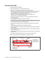
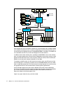
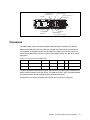
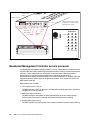
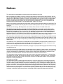
IBM Redbooks Paper David Watts Robert Moon IBM Eserver xSeries 366 Technical Introduction Delivering an industry-leading, 64-bit framework for mid-tier application development, the IBM Eserver® xSeries® 366 is built on the power of the IBM® eServer X3 Architecture, the third generation of IBM Enterprise X-Architecture™ technology. X3 Architecture drives the x366 to deliver the performance, availability, and manageability required for the next generation of industry-standard servers. Four-socket performance and 64-bit memory addressability provide an optimized platform for the application-serving tier. At the crossroads of a major industry transition to mainstream 64-bit applications, X3 Architecture delivers a formidable combination of 64-bit performance, availability, and investment protection not yet available in an industry-standard x86 server. With its extensive chipset development experience and industry-leading performance and availability breakthroughs, IBM is uniquely positioned to propose a robust and powerful server, offering innovation that delivers real business and IT results. Figure 1 The IBM Eserver xSeries 366 © Copyright IBM Corp. 2005. All rights reserved. ibm.com/redbooks 1 Overview of the x366 The key features of the x366 include: Four-way capable server in a rack-dense 3U form factor. IBM Eserver X3 Architecture, the XA-64e third-generation chipset. Models with one Intel® Xeon MP processor, up to 3.66 GHz and 1 MB L2 cache, which can be upgraded to four-way. Processors support 64-bit addressing with the Intel Extended Memory 64 Technology (EM64T) architecture. Memory: 2 GB standard expandable to 64 GB (with 4 GB DIMMs), using high-performance PC2-3200 ECC DDR2 DIMMs. Active Memory with Memory ProteXion, memory mirroring, memory hot-swap and hot-add, and ChipKill. Six full-length 64-bit 266 MHz PCI-X 2.0 Active PCI slots. Integrated Adaptec AIC-9410 serial-attached SCSI (SAS) controller. Support for internal RAID arrays using an optional ServeRAID™-8i adapter. ServeRAID-6M is also supported for external SCSI storage, with the EXP400 enclosure. Six internal hot-swap drive bays for up to 440 GB of internal storage (using 73.4 GB disks). Integrated Dual-port Broadcom 5704 PCI-X Gigabit Ethernet. Baseboard Management Controller standard with optional Remote Supervisor Adapter II SlimLine adapter. Supports the IBM Integrated xSeries Adapter for iSeries™ (IXA) for a direct high-speed link to an iSeries server. Three-year warranty, on-site, nine hours per day, five days per week, with a next business day response. The x366 is targeted at ERP, database, e-mail, and e-commerce applications. Figure 2 shows the x366 and major components on the front of the unit. Six hot-swap disk drive bays USB port Processor tray (behind bezel) Figure 2 Front panel of the x366 2 IBM Eserver xSeries 366 Technical Introduction Operator panel Panel release button to display light path panel DVD-ROM drive Dual-core capability: In addition to the single-core Xeon processors MP available today, strategic intent of IBM is to support dual-core microprocessor technology on the x366 server at such a time that this technology becomes generally available from our partners. The strategic intent also includes releasing a dual-core upgrade option kit to enable customers to upgrade from single-core to dual-core technology in the future. In both cases, this support may require updated server components made available in future revisions of the x366. Current models Table 1 shows the x366 models that were announced in March 2005. Table 1 x366 models announced in March 2005 Model Standard/max CPU L2 cache L3 cache Standard/max memory 8863-1RY 1x 3.16 GHz Xeon MP / 4 1 MB None 2 GB (2x 1 MB) / 64 8863-2RY 1x 3.66 GHz Xeon MP / 4 1 MB None 2 GB (2x 1 MB) / 64 Note: x366 Express models are also available in some geographies. These systems have additional processors, memory, disk, or a second power supply standard. Consult your sales representative for more information. The x366 supports one, two, three, or four processors. Both models support a maximum of 64 GB using 4 GB DIMMs in 16 sockets. To achieve the maximum, you will need to install three additional memory cards (one four-socket card is standard), remove the standard pair of 1 GB DIMMs and insert 16 DIMMs. The x366 has six internal PCI-X 2.0 slots. Unlike the x365, the x366 does not support the attachment of an RXE-100 Remote Expansion Enclosure. The RSA II SlimLine and ServeRAID-8i options do not use any of these six PCI-X slots. IBM XA-64e third-generation chipset The x366 uses the third generation of the IBM XA-64e chipset. The architecture consists of the following components: One to four Xeon MP processors One Hurricane Memory and I/O Controller (MIOC) Two Calgary PCI Bridges Figure 3 on page 4 shows the block diagram of the x366. IBM Eserver xSeries 366 Technical Introduction 3 CPU 1 CPU 2 667 MHz 5.33 GBps DDR2 SMI2 DDR2 SMI2 DDR2 SMI2 DDR2 SMI2 Each: 667 MHz 5.33 GBps PCI-X bridge 33 66 CPU 4 667 MHz 5.33 GBps Memory controller 6 GBps Calgary CPU 3 IBM XA-64e core chipset Hurricane 6 GBps 6 GBps PCI-X bridge 266 266 MHz 266 MHz Video RSA SL 1 USB 2.0 ServeRAID South bridge Adaptec SAS EIDE K/M Serial 2 3 4 5 6 HDD backplane Gigabit Ethernet Six PCI-X 2.0 slots: 64-bit 266 MHz Figure 3 xSeries 366 system block diagram Each memory port out of the memory controller has a peak throughput of 5.33 GBps. DIMMs are installed in matched pairs (that is, two-way interleaving) to ensure that the memory port is fully utilized. Peak throughput for each PC2-3200 DDR2 DIMM is 2.67 GBps. (The DIMMs are run at 333 MHz to remain in sync with the throughput of the front-side bus.) In addition, there are four memory ports; spreading installed DIMMs across all four memory ports can improve performance, because the four independent memory ports (memory cards) provide simultaneous/concurrent access to memory. With four memory cards installed (and DIMMs in each card), peak memory bandwidth is 21.33 GBps. The memory controller routes all traffic from the four memory ports, two CPU ports and the two PCI bridge ports. The memory controller also has embedded DRAM, which in the x366 holds a snoop filter lookup table. This filter ensures that snoop requests for cache lines go to the appropriate CPU bus and not both of them, thereby improving performance. One PCI bridge supplies four of the six 64-bit 266 MHz PCI-X slots on four independent PCI-X buses. The other PCI bridge supplies the other two PCI-X slots (also 64-bit, 266 MHz), plus all the onboard PCI devices, including the optional ServeRAID-8i and Remote Supervisor Adapter II SlimLine daughter cards. Figure 4 on page 5 shows the rear panel of the x366. 4 IBM Eserver xSeries 366 Technical Introduction Service processor Ethernet port System serial port Service processor serial port 2x USB Mouse Keyboard Video 2x Gigabit Ethernet IXA RS-485 (not service processor) Figure 4 Rear view of the x366 Processors The x366 models use the Intel Xeon Processor MP with EM64T extensions (“Cranford”). Models of the x366 come with one processor installed. One, two, three, or four processors are supported. Installed processors must be identical in speed and cache size. There are currently two x366 models, as listed in Table 2. Both models support one, two, three, or four processors. Table 2 Processors used in the x366 models Model Processor L2 cache L3 cache Installed Max Upgrade option 8863-1RY Xeon MP 3.16 GHz 1 MB 0 MB 1 4 13N0694 8863-2RY Xeon MP 3.66 GHz 1 MB 0 MB 1 4 13N0695 The upgrade options include one processor and one VRM. The VRM must be installed if the option is to be installed as CPU 3 or CPU 4. The VRMs for CPUs 1 and 2 are integrated onto the processor board. See the x366 Installation Guide for more details. The processors are easily accessible from the front of the server on a sliding tray. IBM Eserver xSeries 366 Technical Introduction 5 O FR 1 N T O FR 2 N T O FR 3 N T 4 The processor tray pulls out from the front of the server and houses the CPUs, VRMs, and memory controller. Figure 5 x366 processor tray The “Cranford” Xeon MP processor has two levels of cache on the processor die: L2 cache is 1 MB in size. The L2 cache implements the Advanced Transfer Cache technology, which means L2-to-processor transfers occur across a 256-bit bus in only one clock cycle. L1 execution trace cache is used to store micro-operations (that is, decoded executable machine instructions); it serves those to the processor at rated speed. This additional level of cache saves decode time on cache hits. Key features of the processors used in the x366 include: 667 MHz front-side bus The Pentium® III Xeon processor in older servers had a 100 MHz front-side bus that equated a burst throughput of 800 MBps. With protocols such as TCP/IP, this has been shown to be a bottleneck in high-throughput situations. The “Cranford” Xeon Processor MP improves on this by using two 133 MHz clocks, out of phase with each other by 90° and using both edges of each clock to transmit data. This is shown in Figure 6. 133 MHz clock A 133 MHz clock B Figure 6 Quad-pumped frontside bus This increases the performance of the frontside bus without the difficulty of high-speed clock signal integrity issues. Because the bus is 8 bytes wide, the end result is an effective burst throughput of 5.33 GBps, which can have a substantial impact, especially on TCP/IP-based LAN traffic. 6 IBM Eserver xSeries 366 Technical Introduction Hyper-Threading Hyper-Threading Technology enables a single physical processor to execute two separate code streams (threads) concurrently. To the operating system, a processor with Hyper-Threading appears as two logical processors, each of which has its own architectural state (that is, its own data, segment, and control registers) and its own advanced programmable interrupt controller (APIC). Each logical processor can be individually halted, interrupted, or directed to execute a specified thread, independent of the other logical processor on the chip. Unlike a traditional two-way SMP configuration that uses two separate physical processors, the logical processors share the execution resources of the processor core, which include the execution engine, the caches, the system bus interface, and the firmware. Figure 7 outlines the basic layout of a Hyper-Threading-enabled CPU, where you can see that only the components for the architectural state of the CPU have doubled. Physical processor Architectural state Cache Processing resources Processor without Hyper-Threading Logical processor Architectural state Architectural state Cache Processing resources Processor with Hyper-Threading Figure 7 The architectural differences of a Hyper-Threading enabled processor versus a non-Hyper-Threading processor Note: Hyper-Threading is enabled by default on the x366, but can be easily disabled in the BIOS. Hyper-Threading Technology is designed to improve server performance by exploiting the multi-threading capability of operating systems, such as Windows® 2003 and Linux®, and server applications, in such a way as to increase the use of the on-chip execution resources available on these processors. Fewer or slower processors usually achieve the best gains from Hyper-Threading because there is a greater likelihood that the software can spawn sufficient numbers of threads to keep both paths busy. The following performance gains are likely: – Two physical processors: up to approximately 25% performance gain – Four physical processors: up to approximately 15% performance gain – Eight physical processors: up to approximately 10% performance gain Tests have shown that software often limits SMP scalability, but customers should expect improved results as software matures. Best-case applications today are: – Databases – Java™ IBM Eserver xSeries 366 Technical Introduction 7 – Web servers – E-mail Note that Microsoft® licensing of the Windows 2000 Server operating systems is by number of processors (four-way for Server, eight-way for Advanced Server, 32-way for Datacenter Server). Therefore, the appearance of twice as many logical processors can potentially affect the installation of the operating system. Windows Server 2003 understands the concept of physical processors versus logical processors. For more information about Hyper-Threading, see the following Web sites: http://www.intel.com/technology/hyperthread/ http://www.microsoft.com/windows2000/server/evaluation/performance/reports/hype rthread.asp Extended Memory 64 Technology (EM64T) First introduced in the Xeon DP “Nocona” processor, EM64T is a 64-bit extension to the industry standard IA32 32-bit architecture. EM64T adds: – A set of new 64-bit general purpose registers (GPR) – 64-bit instruction pointers – The ability to process data in 64-bit chunks Even though the names of these extensions suggest that the improvements are simply in memory addressability, Intel EM64T is in fact a fully functional 64-bit processor. Tip: For all intents and purposes, Intel EM64T and AMD AMD64 are identical. To reap the full benefit of this technology, you need to have a 64-bit operating system and 64-bit applications that have been recompiled to take full advantage of this architecture. Existing 32-bit applications running on a 64-bit operating system can also benefit from EM64T. The “Cranford” processor limits memory addressibility to 36 bits of addressing. There are three distinct operation modes available in EM64T: – 32-bit legacy mode The first and, in the near future, probably most widely used mode will be the 32-bit legacy mode. In this mode, EM64T processors will act just like any other IA32 compatible processor. You can install your 32-bit operating system on such a system and run 32-bit applications, but you will not be able to make use of the new features such as the flat memory addressing above 4 GB or the additional General Purpose Registers (GPRs). 32-bit applications will run just as fast as they would on any current 32-bit processor. Most of the time, IA32 applications will run even faster because of numerous other improvements that boost performance regardless of the maximum address size. – Compatibility mode The second mode supported by EM64T is the compatibility mode, which is an intermediate mode of the full 64-bit mode described below. To run in compatibility mode, you will need to install a 64-bit operating system and 64-bit drivers. If a 64-bit OS and drivers are installed, the processor will be enabled to support both 32-bit applications and 64-bit applications. The compatibility mode gives you the ability to run a 64-bit operating system while still being able to run unmodified 32-bit applications. Each 32-bit application will still be limited to a maximum of 4 GB of physical memory. However, the 4 GB limit is now imposed on a per-process level, not on a system-wide level. This means that every 8 IBM Eserver xSeries 366 Technical Introduction 32-bit process on this system gets its very own 4 GB of physical memory space (provided sufficient physical memory is installed). This is already a huge improvement compared to IA32, where the operating system kernel and the application had to share 4 GB of physical memory. Additionally, the compatibility mode does not support the virtual 8086 mode, so real-mode legacy applications are not supported. However, 16-bit protected mode applications are supported. – Full 64-bit mode The final mode is the full 64-bit mode. Intel refers to it as the IA-32e mode (AMD refers to this as the long mode). This mode is applied when a 64-bit operating system and 64-bit application are used. In the full 64-bit operating mode, an application can have a virtual address space of up to 40 bits (which equates to 1 TB of addressable memory). The amount of physical memory is determined by how many DIMM slots the server has and the maximum DIMM capacity supported and available at the time. Applications that run in full 64-bit mode will have access to the full physical memory range (depending on the operating system), and to the new GPRs and the expanded GPRs. However, it is important to understand that this mode of operation requires not only a 64-bit operating system (and, of course, 64-bit drivers) but also a 64-bit application that has been recompiled to take full advantage of the various enhancements of the 64-bit addressing architecture. For more information about the features of the Xeon Processor MP, refer to: http://www.intel.com/design/Xeon/xeonmp/prodbref/ For more information about EM64T, see: http://www.intel.com/technology/64bitextensions/ XceL4v Dynamic Server Cache An XceL4 Dynamic Server Cache serves two purposes in the X3 Architecture servers (the x260, x366, and x460): A snoop filter lookup table to reduce traffic on the front side bus (all three servers) A cache for multi-node configurations to reduce latency across the scalability cables in x460 configurations (x460 servers only) With advances in chip design, IBM has now reduced the latency of main memory to below that of the XceL4 cache in the x445. In other words, the time it takes to access data directly from memory is almost as fast as accessing it from L3. As a result, on a four-way system such as the x366, there is little or no need for either a L3 cache or L4 cache (as implemented in the XceL4v). Since the L3 cache is inline, when cache misses do occur, it adds significant overhead to memory access. The L3 cache rate has to be very high for it to keep up with the 3.66 GHz processor. In most server applications with multiple users, the threads competing for L3 cache generate a lower hit rate, and the latency of the L3 drops performance. The same applies to any L4 cache. As a result, there is no performance benefit in implementing neither L3 nor L4 cache on the four-way x366. For these reasons there is 0 MB of XceL4v cache on the x366 server. IBM Eserver xSeries 366 Technical Introduction 9 The XceL4v also functions as a snoop filter lookup table to reduce traffic on the front side bus. Its embedded DRAM (eDRAM) stores a directory of all processor cache lines to minimize snoop traffic on the dual front-side buses and minimize cache misses. System memory The models of the x366 have a 2 GB standard, implemented as two 1 GB PC2-3200 ECC DDR2 DIMMs. Memory is implemented in the x366 using memory cards. Each card has four DIMM sockets. One memory card is standard and the x366 supports up to four memory cards. Using 4 GB DIMMs in every socket (that is, a total of 16 DIMMs), the server can hold 64 GB of RAM. The memory is two-way interleaved (meaning that memory DIMMs are installed in pairs). As shown in Figure 3 on page 4, there are four ports to memory, with each supporting up to 5.33 GBps data transfers. The DIMMs operate at 333 MHz (instead of 400 MHz as for the PC2-3200 spec) so that throughput is 2.67 GBps (333 MHz x 8 bytes). At 2.67 GBps and two-way interleaving, the throughput matches that of the front-side bus at 5.3 GBps so that bus transfers remain in sync. The x366 comes standard with one memory card and two 1 GB DIMMs. Memory is registered ECC DDR2 memory meeting the PC2-3200 standard. Up to four memory cards are supported, and each memory card can hold two or four DIMMs. (DIMMs must be installed in matched pairs.) By adding three additional memory cards (part number 13M7409) and using 4 GB DIMMs (replacing the standard pair of 1 GB DIMMs), the x366 can be expanded to 64 GB. Important: There must be at least one memory card with one matched pair of DIMMs installed for the server to operate. Each memory card requires at least one matched pair of DIMMs. 10 IBM Eserver xSeries 366 Technical Introduction When the cover and bezel are removed, the memory cards are easily accessible (Figure 8). In order to replace or add any DIMM, you need to remove the memory card. See “Memory mirroring” on page 13 and “Hot-add memory” on page 15, to see how this can be done even while the system and the operating system are up and running. Each memory card has four DIMM sockets. DIMMs must be installed in matched pairs. The x366 has one memory card standard and supports up to four cards. Two 1 GB DIMMs are installed standard in card 1. Memory cards can be hot-swapped or hot-added (specific restrictions apply). D C A C Figure 8 x366 memory card and location Key configuration rules: Because the x366 uses two-way interleaving memory, DIMMs must be installed in matched pairs. Supported DIMM options are: – 2 GB (part number 73P2866) containing two 1 GB DIMMs – 4 GB (part number 73P2867) containing two 2 GB DIMMs – 8 GB (part number 30R5145) containing two 4 GB DIMMs Memory cards have part number 13M7409. One is standard and up to four can be installed. Each memory card has four DIMM sockets. There are two ways to fill the DIMMs sockets, depending on whether cost or performance is the more important consideration: – Cost-effective configuration: To minimize cost, you can install the memory DIMMs by filling each memory card before adding DIMMs to the next memory card. – Performance-optimized configuration: As described in “IBM XA-64e third-generation chipset” on page 3, there are four independent memory ports. Therefore, to optimize performance, you can spread the DIMMS (still installed in matched pairs) across all four memory cards, before filling each card with two more DIMMs. IBM Eserver xSeries 366 Technical Introduction 11 A more detailed description and the exact sequence for installation can be found in the xSeries 366 User’s Guide. If you want to install the full 64 GB, you must remove the existing 1 GB DIMMs and fully populate the x366 with four memory cards, each with four 4 GB DIMMs. Several advanced features are implemented in the x366 memory subsystem, collectively known as Active Memory: Memory ProteXion The Memory ProteXion feature (also known as redundant bit steering) provides the equivalent of a hot-spare drive in a RAID array. It is based in the memory controller, and it enables the server to sense when a chip on a DIMM has failed and to route the data around the failed chip. Normally, 128 bits out of every 144 are used for data and the remaining 16 bits are used for ECC functions. However, the x366 needs only 12 bits to perform the same ECC functions, thus leaving 4 bits free. These 4 bits are equivalent to an x4 memory chip on the DIMM, which Memory ProteXion uses. In the event that a chip failure on the DIMM is detected by memory scrubbing, the memory controller can re-route data around that failed chip through these spare bits. It can do this automatically without issuing a Predictive Failure Analysis® (PFA) or light path diagnostics alert to the administrator (although an event is logged to the service processor log). After the second DIMM failure, PFA and light path diagnostics alerts would occur on that DIMM as normal. Note: In BIOS, there is a Memory Array setting in Advanced Settings. When it is set to High Performance Memory Array, BIOS reconfigures the server for maximum performance at the expense of some fault tolerance features, including Memory ProteXion. For a production environment, we recommend that you do not select this setting, thereby keeping your system protected from memory failures with Memory ProteXion. Memory scrubbing Memory scrubbing is an automatic daily test of all of the system memory that detects and reports memory errors that might be developing before they cause a server outage. Memory scrubbing and Memory ProteXion work in conjunction with each other and do not require memory mirroring to be enabled to work properly. When a bit error is detected, memory scrubbing determines whether the error is recoverable. If it is recoverable, Memory ProteXion is enabled and the data that was stored in the damaged locations is rewritten to a new location. The error is then reported so that preventive maintenance can be performed. As long as there are enough good locations to allow the proper operation of the server, no further action is taken other than recording the error in the error logs. If the error is not recoverable, then memory scrubbing sends an error message to the light path diagnostics, which turns on the proper lights and LEDs to guide you to the damaged DIMM. If memory mirroring is enabled, then the mirrored copy of the data from the damaged DIMM is used until the system is powered down and the DIMM is replaced. Memory mirroring Memory mirroring is roughly equivalent to RAID-1 in disk arrays, in that usable memory is halved and a second copy of data is written to the other half. If 8 GB is installed, then the operating system sees 4 GB when memory mirroring is enabled. (It is disabled in the BIOS 12 IBM Eserver xSeries 366 Technical Introduction by default.) Because all mirroring activities are handled by the hardware, memory mirroring is operating system independent. When memory mirroring is enabled, certain restrictions exist with respect to placement and size of memory DIMMs and the placement and removal of memory cards. These topics are discussed in “Memory mirroring” on page 13. Chipkill™ memory Chipkill is integrated into the XA-64e chipset, so it does not require special Chipkill DIMMs and is transparent to the operating system. When combining Chipkill with Memory ProteXion and Active Memory, the x366 provides very high reliability in the memory subsystem. When a memory chip failure occurs, Memory ProteXion transparently handles the rerouting of data around the failed component as described above. However, if a further failure occurs, the Chipkill component in the memory controller reroutes data. The memory controller provides memory protection similar in concept to disk array striping with parity, writing the memory bits across multiple memory chips on the DIMM. The controller can reconstruct the “missing” bit from the failed chip and continues working as usual. One of these additional failures can be handled per memory port (a total of four Chipkill recoveries). Hot-add and hot-swap memory The x366 supports the replacing of failed DIMMs while the server is still running. This hot-swap support works in conjunction with memory mirroring. The server also supports adding additional memory while the server is running. Adding memory requires operating system support. These two features are mutually exclusive. Hot-add requires that memory mirroring be disabled and hot-swap requires that memory mirroring be enabled. These features are discussed in “Hot-swap memory” on page 14 and “Hot-add memory” on page 15. In addition, to maintain the highest levels of system availability, if a memory error is detected during POST or memory configuration, the server can automatically disable the failing memory bank and continue operating with reduced memory capacity. You can manually re-enable the memory bank after the problem is corrected by using the Setup menu in the BIOS. Memory mirroring, Chipkill, and Memory ProteXion provide multiple levels of redundancy to the memory subsystem. Combining Chipkill with Memory ProteXion allows up to two memory chip failures per memory port on the x366, for a total of eight failures sustained. 1. The first failure detected by the Chipkill algorithm on each port does not generate a light path diagnostics error, as Memory ProteXion recovers from the problem automatically. 2. Each memory port could then sustain a second chip failure without shutting down. 3. Provided that memory mirroring is enabled, the third chip failure on that port would send the alert and take the DIMM offline, but keep the system running out of the redundant memory bank. Memory mirroring Memory mirroring is available on the x366 for increased fault tolerance. Memory mirroring is operating system independent, since all mirroring activities are handled by the hardware. IBM Eserver xSeries 366 Technical Introduction 13 To understand what memory mirroring and hot-swap capabilities exist with the server, you must first understand how the memory cards are powered. The x366 has two separate memory power buses that are split between the four memory cards. As shown in Figure 9, memory cards 1 and 2 are on power bus 1, and memory cards 3 and 4 are on power bus 2. Four memory cards (card 1 standard) Power bus 1 (cards 1 & 2) Hot-swap enabled LED 1 2 Memory port power LED DIMM Socket 1 3 4 Power bus 2 (cards 3 & 4) DIMM Socket 4 Each card has four DIMM sockets Card 1 has sockets 1 and 3 filled with 1 GB DIMMs Figure 9 Memory hardware on the x366 Mirroring takes place across the two power buses. In other words, the memory DIMMs in cards 1 and 2 are mirrored to the memory DIMMs in cards 3 and 4. With memory mirroring enabled in BIOS, you can hot-swap one memory card at a time on each memory power bus. Once memory mirroring is enabled, the data that is written to memory will be stored in two locations. For read operations, data is read from the DIMMs with the least amount of reported memory errors through memory scrubbing. Memory scrubbing is an automatic and regular test of all the system memory that detects and reports memory errors before they cause a server outage. If memory scrubbing determines that the DIMM is damaged beyond use, read and write operations are redirected to the remaining good DIMM. Memory scrubbing then reports the damaged DIMM and the light path diagnostic displays the error. If memory mirroring is enabled, then the mirrored copy of the data from the damaged DIMM is used until the system is powered down and the DIMM replaced. After the damaged DIMM is replaced, memory mirroring will copy the mirrored data back onto the new DIMM. Key configuration rules relating to memory mirroring are as follows: Memory mirroring must be enabled in the BIOS (it is disabled by default). Both memory cards must have the same total amount of memory, and must have identical DIMMs. In other words, DIMMs must be installed in matched quads to support memory mirroring. Partial mirroring is not supported. See the x366 Installation Guide for information about the exact installation order required. Important: Because of memory mirroring, you will only have half of the total amount of memory available. If 8 GB is installed, for example, then the operating system sees 4 GB once memory mirroring is enabled (it is disabled in the BIOS by default). Hot-swap memory The x366 supports hot-swap memory, which means that if a DIMM fails, it can be replaced with a new DIMM without powering down the server. This advanced feature allows for maximum system availability. Hot-swap memory requires that memory mirroring be enabled. 14 IBM Eserver xSeries 366 Technical Introduction To easily identify whether hot-swap is enabled and the status of power to the memory card, each memory card has a green memory hot-swap enable LED, and a green memory port power LED on the top panel of the memory card, as shown in Figure 9 on page 14. The memory card has eject levers with sensors, so that the system can recognize when a memory card is being removed and power down that card’s slot accordingly. The overall process to hot-swap a failed DIMM is as follows: 1. Verify that memory mirroring and hot-swap are enabled by checking the memory hot-swap enable LED on the memory cards. 2. When a DIMM fails, you will be alerted via the memory LED on the light path diagnostics panel (and by other means via the service processor if this has been configured). 3. Locate the memory card with the failed DIMM by using the Error LED on the memory card. 4. Remove the memory card containing the failed DIMM. 5. Press the button on the memory card to identify which DIMM has failed. The LED next to the failed DIMMs lights up. 6. Replace the failed DIMM and reinsert the memory card. For a more detailed description of how to correctly hot-swap memory and which sequence to follow, see the x366 User’s Guide. Hot-add memory The hot-add memory feature enables you to add DIMMs without turning off the server. This section shows the requirements for enabling the hot-add memory feature on the server. Note: Hot-add and hot-swap are mutually exclusive. You can enable only one of these features. The requirements are as follows: Operating system support: Adding usable system memory to a running operating system requires operating system support. This is done via an ACPI sequence. Currently, the only operating system that has this capability and is supported on the x366 is Windows Server 2003, Enterprise Edition. Memory hot-add must be specifically enabled in the BIOS setup. When this is done, the system allocates blank windows of memory space for future memory additions. By enabling hot-add, memory mirroring will automatically be disabled. Memory cards 3 and 4 must not be installed yet because these are the only ones that can be hot-added. If only one memory card is installed (memory card 1) prior to the hot-add operation, then only one additional memory card may be added in slot 3. If two memory cards (1 and 2) are already in the system, then two additional memory cards must be added in slots 3 and 4. The card in slot 4 must be inserted first because power to the second bus will be applied after card 3 is inserted and closed. The DIMMs must be added two at a time (matched pairs) and they must also match the equivalent pair of DIMMs on the matching memory card on the other power bus. A minimum of 4 GB of memory must be installed in the server in order for hot-add memory to be available. Additionally, for 32-bit operating systems, the Physical Address Extension (PAE) mode has to be enabled to take advantage of the additional memory. IBM Eserver xSeries 366 Technical Introduction 15 For information about performing a hot-add operation, and more information about the restrictions, see the x366 User’s Guide. Notes: After you have added a memory card with two DIMMs, you cannot add more memory to that same memory card without powering off the server. Enabling hot-add reserves a portion of the memory map for the memory that may be hot-added in the future. If you do not plan to use hot-add, we recommend that you not enable this feature in BIOS. Memory configuration in BIOS You configure the memory subsystem in the server’s BIOS Setup menu by clicking Advanced Settings → Memory → Memory Array Setting. Table 3 shows the choices. Table 3 Memory configuration modes in BIOS Mode Memory ProteXion Memorymirroring Hot-swap memory Hot-add memory HPMA (high performance memory array) Disabled Disabled Disabled Disabled RBS (redundant bit steering) Yes Disabled Disabled Disabled FAMM (full array memory mirroring) Yes Yes Yes Disabled HAM (hot-add memory) Yes Disabled Disabled Yes Your memory configuration mode selection depends on the memory features you want to use: Select RBS if you are not using mirroring, hot-swap, or hot-add. This is the default/standard setting. Select FAMM to enable memory mirroring (and to enable hot-swap). Select HAM to enable hot-add in the future. We recommend that you do not select the HPMA setting as this disables Memory ProteXion. Serial Attached SCSI The x366 has a disk subsystem that is comprised of an Adaptec AIC-9410 Serial Attached SCSI (SAS) controller and six internal hot-swap drive bays. The x366 does not support RAID as standard, but the server also supports the addition of the ServeRAID-8i daughter card (part 13N2227). Serial Attached SCSI (SAS) is the logical evolution of SCSI. SAS uses much smaller interconnects than SCSI, while offering SCSI compatibility, reliability, performance, and manageability. In addition, SAS offers longer cabling distances, smaller form factors and greater addressability. 16 IBM Eserver xSeries 366 Technical Introduction SAS 1.0 technology is replacing Ultra320 SCSI in SCSI and RAID controllers. Beyond the upgrades in I/O processor and memory speeds, SAS-based products will differ from SCSI-based products in the following ways: Higher bandwidth Ultra320 SCSI supports 320 MBps of bandwidth per channel. SAS 1.0 supports 3 Gbps (approximately 300 MBps) of bandwidth per port. So although the two Ultra320 SCSI channels of the ServeRAID-6M can potentially support 640 MBps of bandwidth, the onboard SAS controller with its 8 ports could support up to 24 Gbps (approximately 2.4 GBps) of bandwidth. Therefore, bandwidth is limited by PCI-X or PCI Express bus speeds. Greater drive support SCSI-based products support 14 drives per channel. By cascading drive enclosures, SAS-based products will support up to 72 drives per 4 ports. Although this is not directly relevant to the x366 and the ServeRAID-8i because the supported SAS drives are only in the six internal drive bays, it is indicative of the advances in the technology and the future capabilities of ServeRAID SAS adapters with external storage connectivity. The SCSI subsystem includes an Adaptec AIC-9410 single chip Serial Attached SCSI (SAS), which does not support any RAID. To enable RAID support, an optional ServeRAID-8i SAS RAID controller (part number 13N2227) can be installed in a dedicated slot. The ServeRAID-8i enables the following RAID levels: RAID-0 RAID-1 RAID-1E RAID-5 RAID-5EE RAID-6 RAID-10 RAID-60 (although the x366 does not support this RAID level since it requires 8 drives) The ServeRAID-8i has the following possible stripe sizes: 16 KB, 32 KB, 64 KB, 128 KB, 256 KB, and 512 KB. 64 KB is the default stripe size. The adapter supports up to 24 logical drives. The ServeRAID-8i does not have any connectors for external SAS devices. The ServeRAID-8i supports two additional RAID levels compared to other ServeRAID controllers: RAID-6 is a multiparity type that requires a minimum of four drives, of which two drives’ worth of capacity are consumed for redundancy. RAID-6 allows the loss of two drives without data loss, but this loss is associated with a substantial performance degradation. RAID-60 is a hierarchical array made up of multiple RAID-6 arrays at the lower level with data striped over these arrays (the 0 in 60) at the upper level. Even though the ServeRAID-8i supports this RAID level, it is not supported on the x366 because it requires a minimum of 8 drives. For external SCSI disk enclosures attachment, such as the EXP400, the ServeRAID-6M can be installed. Because this card is based on SCSI architecture, it is incompatible with the SAS subsystem and therefore cannot be used to run the internal disks. The following drives are supported in the x366: 36.4 GB, 10 K RPM 2.5” SAS drive, part number 26K5654 73.4 GB, 10 K RPM 2.5” SAS drive, part number 26K5655 IBM Eserver xSeries 366 Technical Introduction 17 See ServerProven® for the latest list of supported adapters and hot-swap SAS drives: http://www.pc.ibm.com/us/compat/xseries/controllers/matrix.html For a comparison of features of members of the ServeRAID family, see: http://www.redbooks.ibm.com/abstracts/tips0054.html PCI subsystem As shown in Figure 3 on page 4, there are six full-length hot-swap PCI-X 2.0 slots internal to the x366, and all are vacant in the standard models. All six slots have the following characteristics: Separate bus from the other slots and devices (therefore, the speed of the adapter does not affect the other adapters) PCI-X 2.0 266 MHz (each supports lower speed adapters) 64-bit (each supports 32-bit adapters as well) 3.3 V One additional dedicated PCI slot is reserved for the ServeRAID-8i adapter as described below. The PCI subsystem also supplies these I/O devices: Adaptec AIC-9410 Serial-attached SCSI (SAS) controller Broadcom dual port 5704 10/100/1000 Ethernet ATI 7000-M video controller (with 16 MB video memory) Three USB ports (one on the front panel, two on the rear) Optional Remote Supervisor Adapter II SlimLine adapter (installed into a dedicated socket on the I/O board) EIDE interface for the DVD-ROM drive Serial port Note: There is no parallel port on the x366. For parallel port connections, use the NetVista™ USB Parallel Printer Cable, part number 19K4164. 18 IBM Eserver xSeries 366 Technical Introduction x366 PCI slots As shown in Figure 3 on page 4, there are six full-length 64-bit PCI-X slots. PCI slot 1 266 MHz 64-bit PCI-X slot 2 266 MHz 64-bit PCI-X slot 3 266 MHz 64-bit PCI-X slot 4 266 MHz 64-bit PCI-X slot 5 266 MHz 64-bit PCI-X slot 6 266 MHz 64-bit Figure 10 PCI-X slots The six slots all support hot-plug PCI-X 3.3 V, 32-bit or 64-bit PCI, and PCI-X 2.0 adapters. Further configuration information includes: Video adapters are not supported. The PCI slots support 3.3 V adapters only. 5 V adapters, such as the Adaptec2944UW, are not supported. The system scans PCI-X slots to assign system resources. The system attempts to start the first device found. The search order is as follows: a. b. c. d. DVD-ROM Integrated dual Gigabit Ethernet controller Integrated SAS devices Internal PCI and PCI-X slots (in the order 1, 2, 3, 4, 5, 6) Restriction: The x366 does not support the connectivity to external PCI slot enclosures such as the RXE-100. Broadcom dual Gigabit Ethernet controller The x366 offers a dual Gigabit Ethernet controller integrated standard in the system. The x366 includes one dual-port Broadcom BCM5704 10/100/1000 BASE-T MAC (Media Access Controller) on the PCI-X 64-bit 100 MHz bus. The BCM5704 has the following features: Supports full and half-duplex performance at all speeds (10/100/1000 Mbps, auto-negotiated) Includes integrated on-chip memory for buffering data transmissions to ensure the highest network performance IBM Eserver xSeries 366 Technical Introduction 19 Includes dual onboard RISC processors for advanced packet parsing Offers backward compatibility with today's 10/100 network The Broadcom controller also includes software support for failover, layer-3 load balancing, and comprehensive diagnostics. Category 5 or better Ethernet cabling is required with RJ-45 connectors. If you plan to implement a Gigabit Ethernet connection, ensure that your network infrastructure is capable of the necessary throughput to match the server’s I/O capacity. Redundancy The x366 has the following redundancy features to maintain high availability. There are eight hot-swap multi-speed fans. These fans provide cooling redundancy and enable individual fan replacement without powering down the server. Each of the two groups of four fans is redundant. In the event of a fan failure, the other fans will speed up to continue to provide adequate cooling until the fan can be hot-swapped by the IT administrator. In general, failed fans should be replaced within 48 hours following failure. The two Gigabit Ethernet ports can be configured as a team to form a redundant pair. The memory subsystem has several redundancy features, including memory mirroring and Memory ProteXion, as described in “System memory” on page 10. Support is available for RAID disk arrays, both with the ServeRAID-8i (for internal RAID arrays) and the ServeRAID-6M for external arrays. The x366 has six internal hot-swap disk drive bays. A optional second 1300 W hot-swap power supply is available and connected using a separate power cord. At 220 V, this second power supply is redundant in all configurations. At 110 V, the second power supply is redundant except in full configurations (in which case NONRED will light up on the light path diagnostics panel). Important: At 110 V and with a heavily configured server, two power supplies may be needed; the second power supply may not be redundant. Figure 11 on page 21 displays the layout of the x366, showing the location of the drive bays, power supplies, and fans. 20 IBM Eserver xSeries 366 Technical Introduction Four hot-swap fans (one redundant) Memory redundancy features: memory mirroring, Memory ProteXion, and ChipKill Hot-swap drive bays and optional ServeRAID-8i RAID controller offer redundancy Four hot-swap fans (one redundant) Two hot-swap power supplies (one redundant) Figure 11 Redundancy features of the x366 Light path diagnostics To limit the need to slide the server out of the rack to diagnose problems, a light path diagnostics panel is located at the front of the x366. This panel slides out from the front of the server so the customer can view all light path diagnostics monitored server subsystems. In the event that maintenance is required, the customer can slide the server out from the rack and, using the LEDs, find the failed or failing component. Light path diagnostics can monitor and report on the health of CPUs, main memory, hard disk drives, PCI-X and PCI adapters, fans, power supplies, VRMs, and the internal system temperature. IBM Eserver xSeries 366 Technical Introduction 21 Power-control button USB connector Release latch - slide to the left and pull out to display the light path diagnostics panel Power-on LED Locator LED Light Path Diagnostics System error Hard disk drive activity Information LED OVER SPEC REMIND PS LINK CPU VRM LOG MEM NMI PCI SP DASD RAID NONRED TEMP PCI BRD CPU BRD FAN I/O BRD Figure 12 Light path diagnostic panel Baseboard Management Controller service processor The Baseboard Management Controller (BMC) is a small, independent micro-controller used to perform low-level system monitoring and control functions, as well as remote IPMI interface functions. It uses multiple I2C bus connections to communicate out-of-band with other onboard devices. The BMC provides environmental monitoring for the server. If environmental conditions exceed thresholds or if system components fail, the BMC lights the light path diagnostic LEDs to help you diagnose the problem, and it records the error in the BMC system event log. BMC functions are as follows: Initial system check at A/C on The BMC monitors critical I2C devices in standby power mode to determine if the system configuration is safe for power on. BMC Event log maintenance The BMC maintains and updates an IPMI-specified event log in non-volatile storage. Critical system information is recorded and made available for external viewing. System power state tracking The BMC monitors the system power state and logs transitions into the system event log. 22 IBM Eserver xSeries 366 Technical Introduction System initialization The BMC has I2C access to certain system components that may require initialization before power-up. System software state tracking The BMC monitors the system and reports when the BIOS and POST phases are complete and the operating system has booted. System event monitoring During runtime, the BMC continually monitors critical system items such as fans, power supplies, temperatures, and voltages. The system status is logged and reported to the service processor, if present. System fan speed control The BMC monitors system temperatures and adjusts fan speed accordingly. The BMC also provides the following remote server management capabilities through the OSA SMBridge management utility program: Command-line interface (IPMI Shell) Serial over LAN (SOL) For more information about how to enable and configure these management utilities, see the x366 User’s Guide. Remote Supervisor Adapter II SlimLine The x366 can be upgraded with the Remote Supervisor Adapter II SlimLine service processor to enable full RSA II support. This adapter, which installs in a dedicated slot, provides a function similar to the Remote Supervisor Adapter II PCI option that is available for other xSeries servers. Figure 13 Remote Supervisor Adapter II SlimLine daughter card Key features of the Remote Supervisor Adapter II SlimLine include: IBM ASIC with integrated PowerPC® 405 core executing at 200 MHz 16 MB SDRAM and 4 MB flash ROM System-independent graphical console redirection – Built-in video compression hardware eliminates drivers. – Graphics response, up to five times faster than with the RSA I, makes monitoring and control more efficient. IBM Eserver xSeries 366 Technical Introduction 23 – System-independent installation eliminates the need to install service processor drivers, helps save IT staff time, and reduces installation complexity. Remote diskette and CD-ROM drive support – Enables remote booting and software loading of the server for application or operating system installation and updates. – Performs configuration remotely; helps save IT time and money by reducing on-site presence and server downtime. Scriptable command-line interface and text-based serial console redirect – Command-line interface supports program control of server management functions using scripts. – Serial text redirect provides access to text-mode BIOS and text-based system consoles such as Linux, NetWare, and Windows EMS (Emergency Management Services). – Program control of text-based console using scripts. – PPP support. User authentication and authority features – User IDs, passwords, and login permission attributes can be stored in an LDAP server. – Enhanced user authority levels set the access rights for users to match job responsibilities for managing your xSeries servers. – Secure Sockets Layer (SSL) encrypts the data transmitted between the LDAP server and the Remote Supervisor Adapter II. Investment protection – Integrates with IBM Director and Director Agent. Operating system support Table 4 on page 25 lists the supported operating systems for the x366 and the level of support for Hyper-Threading technology provided by the operating system. In the column titled Hyper-Threading: Yes indicates that the operating system recognizes the logical processors and can execute threads on them but is not optimized for Hyper-Threading. From a licensing perspective, if Hyper-Threading is enabled, the operating system must be licensed for twice the number of physical processors to take full advantage of the processors’ capabilities. Optimized indicates that the operating system recognizes the logical processors and that the operating system code has been designed to take full advantage of the technology. For example, consider a server with two physical processors with Hyper-Threading enabled (that is, four logical processors). If the operating system's scheduler is unaware of Hyper-Threading (“Yes” in the Hyper-Threading column), it would treat all four logical processors the same. As a result, if two processes are eligible to run, the scheduler might put those processes on the two logical processors that are part of the one physical processor. Thus, one physical CPU would be busy while the other CPU is idle, leading to poor overall performance. From a licensing perspective, the logical processors do not count toward the number of processors for which an operating system is licensed. 24 IBM Eserver xSeries 366 Technical Introduction Table 4 x366 operating system support Operating system1 Release Available Hyper-Threading Windows 2000 Server SP4 Yes Yes Windows 2000 Advanced Server SP4 Yes Yes Windows Server 2003, Standard Edition Initial Yes Optimized Windows Server 2003, Enterprise Edition Initial Yes Optimized Windows Server 2003, Standard x64 Edition SP1 Yes Optimized Windows Server 2003, Enterprise x64 Edition SP1 Yes Optimized NetWare 6.5 Yes Optimized Red Hat Enterprise Linux AS for x86 3 Update 2 Yes Optimized Red Hat Enterprise Linux AS for AMD64/EM64T 3 Update 2 Yes Optimized SUSE LINUX Enterprise Server for x86 9 Yes Optimized SUSE LINUX Enterprise Server for AMD64/EM64T 9 Yes Optimized VMware ESX Server 2.5.1 Yes3 Yes Notes for Table 4: 1. Although operating systems may support eight-way or larger systems, scalability is a function of both the operating system and the application/workload. Applications must be specifically designed to take advantage of larger SMP systems. 2. Some operating systems are supported at general availability (GA); these are marked with Yes. Those operating systems marked with Planned are planned to be supported after GA. For the latest operating system support information, go to: http://www.pc.ibm.com/us/compat/nos/matrix.shtml 3. Virtual machines running on VMware ESX Server 2.5 will only be dual processor capable if the VMware ESX Virtual SMP module is also purchased. “Processors” on page 5 also describes the EM64T extension technology; Table 5 lists the levels of support each OS provides for the EM64T technology. Table 5 Operation system support for EM64T modes Operating system 32-bit legacy mode Compatibility mode 64-bit mode Windows 2000 Server Supported No No Windows 2000 Advanced Server Supported No No Windows Server 2003, Standard Edition Supported No No Windows Server 2003, Enterprise Edition Supported No No Windows Server 2003 Standard x64 Edition No Supported Supported Windows Server 2003 Enterprise x64 Edition No Supported Supported NetWare Supported No No Red Hat Enterprise Linux AS for x86 Supported No No Red Hat Enterprise Linux AS for AMD64/Intel EM64T No Supported Supported IBM Eserver xSeries 366 Technical Introduction 25 Operating system 32-bit legacy mode Compatibility mode 64-bit mode SUSE LINUX Enterprise Server for x86 Supported No No SUSE LINUX Enterprise Server for AMD64/EM64T No Supported Supported VMware ESX Server Supported No No The team that wrote this Redpaper This Redpaper was produced by a team of specialists from around the world working at the International Technical Support Organization, Raleigh Center. David Watts is a Consulting IT Specialist at the IBM ITSO Center in Raleigh. He manages residencies and produces Redbooks™ on hardware and software topics related to IBM Eserver xSeries systems and associated client platforms. He has authored more than 30 IBM Redbooks and Redpapers. He holds a Bachelor of Engineering degree from the University of Queensland (Australia) and has worked for IBM for more than 15 years. He is an IBM Eserver Certified Specialist for xSeries and an IBM Certified IT Specialist. Robert Moon is the team leader at IBM Eserver xSeries Techline in Greenock, Scotland. He is co-author of the x440 and the x445 Solution Assurance Product Review Guides. He has more than nine years of experience in xSeries and Netfinity® servers, including pre-sales and post-sales technical support. He has been involved with Solution Assurance for more than six years, and he is currently the EMEA coordinator for the ServerProven Opportunity Request for Evaluation (SPORE) program. His areas of expertise include Novell NetWare and xSeries hardware. He is an IT Advisory Systems Specialist, chartered professional of the British Computer Society (MBCS CITP), Certified Novell NetWare Administrator (CNA), IBM Eserver Certified specialist for xSeries, and holds a degree in Business Administration and Engineering from the University of Eindhoven. The team (l-r): David and Robert Thanks to the following people for their contributions to this project: Ralph Begun, xSeries 366 Lead Engineer, Raleigh Donn Bullock, WW Brand Manager, Raleigh Rusty Dunnavant, SMB Sector Portfolio Manager, Raleigh 26 IBM Eserver xSeries 366 Technical Introduction Jocelyn Johnstone, ITS Service Development, WINTEL Platform, Greenock Randy Kolvick, xSeries 366 System Engineer, Raleigh John McAbel, WW Solutions Marketing Manager for xSeries, Beaverton Colin McKerrel, Global Solutions, Raleigh Jim Marschausen, WW SPORE Manager, xSeries Compatibility Lab Test Lead, Raleigh Rick Rudd, WW Brand Manager, Raleigh IBM Eserver xSeries 366 Technical Introduction 27 28 IBM Eserver xSeries 366 Technical Introduction Notices This information was developed for products and services offered in the U.S.A. IBM may not offer the products, services, or features discussed in this document in other countries. Consult your local IBM representative for information on the products and services currently available in your area. Any reference to an IBM product, program, or service is not intended to state or imply that only that IBM product, program, or service may be used. Any functionally equivalent product, program, or service that does not infringe any IBM intellectual property right may be used instead. However, it is the user's responsibility to evaluate and verify the operation of any non-IBM product, program, or service. IBM may have patents or pending patent applications covering subject matter described in this document. The furnishing of this document does not give you any license to these patents. You can send license inquiries, in writing, to: IBM Director of Licensing, IBM Corporation, North Castle Drive Armonk, NY 10504-1785 U.S.A. The following paragraph does not apply to the United Kingdom or any other country where such provisions are inconsistent with local law: INTERNATIONAL BUSINESS MACHINES CORPORATION PROVIDES THIS PUBLICATION "AS IS" WITHOUT WARRANTY OF ANY KIND, EITHER EXPRESS OR IMPLIED, INCLUDING, BUT NOT LIMITED TO, THE IMPLIED WARRANTIES OF NON-INFRINGEMENT, MERCHANTABILITY OR FITNESS FOR A PARTICULAR PURPOSE. Some states do not allow disclaimer of express or implied warranties in certain transactions, therefore, this statement may not apply to you. This information could include technical inaccuracies or typographical errors. Changes are periodically made to the information herein; these changes will be incorporated in new editions of the publication. IBM may make improvements and/or changes in the product(s) and/or the program(s) described in this publication at any time without notice. Any references in this information to non-IBM Web sites are provided for convenience only and do not in any manner serve as an endorsement of those Web sites. The materials at those Web sites are not part of the materials for this IBM product and use of those Web sites is at your own risk. IBM may use or distribute any of the information you supply in any way it believes appropriate without incurring any obligation to you. Information concerning non-IBM products was obtained from the suppliers of those products, their published announcements or other publicly available sources. IBM has not tested those products and cannot confirm the accuracy of performance, compatibility or any other claims related to non-IBM products. Questions on the capabilities of non-IBM products should be addressed to the suppliers of those products. This information contains examples of data and reports used in daily business operations. To illustrate them as completely as possible, the examples include the names of individuals, companies, brands, and products. All of these names are fictitious and any similarity to the names and addresses used by an actual business enterprise is entirely coincidental. COPYRIGHT LICENSE: This information contains sample application programs in source language, which illustrates programming techniques on various operating platforms. You may copy, modify, and distribute these sample programs in any form without payment to IBM, for the purposes of developing, using, marketing or distributing application programs conforming to the application programming interface for the operating platform for which the sample programs are written. These examples have not been thoroughly tested under all conditions. IBM, therefore, cannot guarantee or imply reliability, serviceability, or function of these programs. You may copy, modify, and distribute these sample programs in any form without payment to IBM for the purposes of developing, using, marketing, or distributing application programs conforming to IBM's application programming interfaces. © Copyright IBM Corp. 2005. All rights reserved. 29 This document created or updated on October 12, 2005. ® Send us your comments in one of the following ways: Use the online Contact us review redbook form found at: ibm.com/redbooks Send your comments in an email to: [email protected] Mail your comments to: IBM Corporation, International Technical Support Organization Dept. HZ8 Building 662 P.O. Box 12195 Research Triangle Park, NC 27709-2195 U.S.A. Trademarks The following terms are trademarks of the International Business Machines Corporation in the United States, other countries, or both: Chipkill™ Eserver® Eserver® IBM® iSeries™ Netfinity® NetVista™ PowerPC® Predictive Failure Analysis® Redbooks™ Redbooks (logo) ServerProven® ServeRAID™ X-Architecture™ xSeries® ™ The following terms are trademarks of other companies: Java and all Java-based trademarks and logos are trademarks or registered trademarks of Sun Microsystems, Inc. in the United States, other countries, or both. Microsoft, Windows, and the Windows logo are trademarks of Microsoft Corporation in the United States, other countries, or both. Intel, Intel Inside (logos), and Pentium are trademarks of Intel Corporation in the United States, other countries, or both. Linux is a trademark of Linus Torvalds in the United States, other countries, or both. Other company, product, and service names may be trademarks or service marks of others. 30 IBM Eserver xSeries 366 Technical Introduction