1
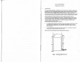
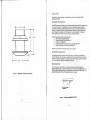
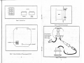
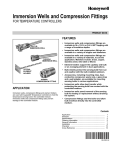
SIGNETMARINE
SL 172
Instruction Manual
2315 1/2 Artesia Blvd.
Redondo Beach, CA 90278
Ph. (310) 320-4349 FAX (310) 320-5026
www.signetmarine.com
[email protected]
TABLE OF CON'IENTS
r.
Introduction.
II .
Installation.
·· .. ·········1
.
.
.
III. Operation. ...
.
·· .... ······8
.
.
IV. Preventative l\-Iaintenance.....
V.
3
11
12
Accessories and Spare Parts..
12
VI. Warranty Statement. ..
Appendix I
Specifications
Appendix II
Trouble Shooting Chart..
. 13
.
. 15
FIGURES
.
Figure 1 Instrument Display Dimensions..
1
Figure 2 Mushroom Transducer Dimensions
2
.
Figure 3 Ccntents.
ii.
Figure 4 Transducer Installation Locations..
.
Figure 5 Completed Transducer Installation.........
3
.
.
···4
Figure 6 Dip Switch Pack
6
Figure 7 Position ofDip Switch
6
Figure 8 Bulkhead Mounting Diagram
7
Figure 9 Electrical Connections.....
7
il
"
"
§
1
f
J
~---~~~==
II
INSTALLATION
This section contains unpacking and installation instructions for the Signet /IIK.172
Depthsounder System,
UNPACKING AND INSPECTION
I-- ",---I
.,
lll-n
rn
FA
(
I
~
3.D5"
~,
3.40"
The MKl72 systems are shipped in special containers designed 1(1 provide full protection under
nonnal transit conditions. Immediately upan receipt, the shipping container should be
inspected for evidence of possible damage incurred in transit. Any obvious damage to the
container, or indications of actual or probable equipment damage, should be reported to the
carrier company in accordance with instructions on the form included in the container.
When unpacking your MK.172, make sure you have received everything.
The MKl72 package eontaiM the following items:
I.
MKl72 Indicator Display (M17240)
2.
Indicator Mounting Clamp Kit (M0201·1)
Protective Cover (M0212.1l
3.
4, Transducer Assembly with nut and 35' Integral Cable (M17285)
Instroction Manual and Warranty Card (Ml7290)
5.
~'
-"
Please fin out and return the warranty card as soon as possible.
~;
TRANSDUCER INSTALLATION
C:
The transducer should be mounted in the hull, liS nellr to the center line II' pOSllible, and
forward of the keel. The mounting area should be free from protroding fitting5, wit1l smooth
water flow (minimum turbulence). A clearance radius of five inches is necessary inside the
hull (in the bilge) for transducer installation and removal.
2.70 •
Special LgcatjllO Tips
Proper installation of the transducer is of utmost importance for obtaining optimum
depth sounder performance. Figure 4 demon.trateo the most popular installation position.
When choosing a mounting position for the tra.ndueer, be sure to consider cable length. The
standa.rd cable length i. 35 feet. Cable lengths cannot be increased.
Figure 2.
Mushroom Transducer Dimensions
v=uF/
IDEAL
~TIO"
_DUC"M
fOIl
J
FiiUl'e 4: Tr1mlIdueeriDltallation location.
2
,
NOTE
If hull thickness is less than 314 inch, a backing plate should be used
on inside of hull at transducer location.
..
b.
o.
..
d.
f.
,
Remove boat from water.
Select location On center line, forward of keel in area of minimum water turbulence.
Transducer should be at least 18 inches from keeL Allow minimum 5-inch clearance
radius for acce.sability inside hull.
Drill 3I8-inch diameter pilot hole through huH (and backing plate, if used).
Cut 1.7f8-inch hole through hull.
Apply bedding compound to inner surface of transducer flange and insert tnmducer shank
through hole from outside hull. Verify proper fit. Small amount of bedding compound
should nude evenly around outer edge of flange.
From inside hull, instan large flanged nut on transducer shank, To properly seat
transducer, tighten nut fmoly with wrench.
Carefully wipe ofT ucess bedding compound from around tran&rlucer flange, Figure 5
shows completed transducer installation.
INSTRUMENT INSTALLATION
The instrument/indicator may be installed in a bulkhead Or instrument panel. The location mu.t
have a clear diameter of 5.50 inches and a reBr clearance of 5 inches (See Figure 1). The installer
should have availabla the following installation tooll:
4.5-inch diameter hole saw
Screwdriver
Bedding compound
CAUTION
Do not use polysulphide bedding compound. such a 3M 3700, Boat Life, Or
Life Caulk on inltrument/indicator. Use silicone, non-hardening
bedding compounds such as GE Silicone Seal.
"-"""""
Before installing the instrument/indicator, the DIP switches must be preset, since they may become
inaccessible after installation. The DIP switch pack is located on the component side of the main
board alSembly. The DIP switch contains four miniature rocker type switches - labelled 1 2 3 4. This
is shown in Figure 6.
Remove three screws from sides ofinst.rument housing; they secure back panel to housing.. Gently
pull back panel away from houling. Entire electronics assembly is attached to back panel, and DIP
switch pack is at left on board assembly, IS shown in Figure 7.
The first switch (11 l, is used tel select feet Or meters, The other switches are used in a binary format tel
set the keel offset (in feet).
To set the indicator to display depth in meten, push switch '1 tel the "OPEN" position. Iffeet are
required, depress the switch to the "'number" position.
-
To set keel offset, fint determine the vertical distance from the transducer location in your boat to the
bottelm of the keeL (The offset control can only handle whole numben.) If, for example, your keel is
3'7" below the tran&rlucer, the number 4 should be selected on the keel offset switch. Table 1 shows the
switch positions VeJ"!l\l!l the desired keel depth.
TABLEt
KEEL OFFSET
,
Figure 5. Completed Tnnllducer Installation
• • •
o
,
•,
OPEN'
,
OPEN'
,
OPEN OPEN'
•
•
OPEN
OPEN'
OPEN
,
OPEN OPEN
OPEN OPEN OPEN
1
3
5
•
SWITCHES
3
•
7
OPEN =
••
Rocker arm pwhed down on OPEN SIDE
of DIP switch.
Rocker arm ia pUJhed down on "number" .ida of DIP lwitch.
5
~
0
i~
W~
0
~
•
•••
[]
•
[]
,
888~
.
• ,
~
o.
.~
.,
••
•
~
r•
~
f?'dl
,
~
~
~
.~
•
00
is
•,
?
"
••
,°••
0
0
!•
'"
c
1(iKij
a
A
!
•
INITIALIZATION
lnslmml'ntllndkalor InstallatioD
When no power is applied, the LCD indicator is blank. When power i. applied, the MKl72 goes
through an initializing routine that may take from Bfew seconds to as long as a half a minute to
complete, depending on water depth when initializing is begun. During initialization, all LCD
segments are displayed in the Built·in Test (BIT) mode while the microprocessor is determining
bottom depth, and the LCD indicates 18.8. This display is an arbitrary number to indicate the LCI:\ is
fuctioning. When the true bottom depth is established, the LCD reveru to the display of that depth
which replaces the BIT test mode pattern.
To install the instrument/indicator. see Figure 8 and use the following procedure,
'.
,b.
..
d.
f.
g.
h.
1lI,
Choose location. )1ake sure location is within reach of cable. and that proper clearance ;s
present.
Cut 4.5-inch diameter hole.
Apply bedding compound or sealant around rear of nangI'.
Insert instrumentlindicator in hole.
Loosen clamp ring and install on housing from rear (see Figure 8) .
With housing nange against bulkhead, position clamp against rear of bulkhead and
tighten o.eturely against housing by turning three bracket screws clockwise until housing
flange is seated snugly against bulkhead. When tightening bracket screws. tighten each
screw a little at a time in rotation $0 that tightness is equally applied. Do not overtighten:
overtightening can eause damp to slip.
Wipe away any e~cen bedding compound from housing flange and bulkhead.
Connect cables as shown in Figure 9.
0,
I,
BOTIOM DEPTH TRACKII\'G
Depth scaling is user selected by ITIM DIP swileh, Bottom depth dale are tracked via last·pulse logic
and displayed in tenths of a foot resolution from three feet to 19,9 feet, then display continues in one_
foot resolution from 20 feet to 199 feet.
If Feet mode is selected and the 199·foot depth measurement limit is uceeded, the elTOr symbol19E is
displayed until a depth Ius than 199 feet is detected: then the depth sounder automatically resumes
normal 'operation and display.
If the transucer emergeJ from the water due to severe listing or pilehing, the last valid depth
indication iJ displayed for five seconds; then the display begins to blink. Blinking indicates no
valid data.
OPERATION
The MKl72 system operates from three fe<lt to 200 feet with the feet/meters DIP switeh in the Feet (IT)
position or to appro~imately 61 meters with the feet/meters DIP switth in the meters (M) position (see
Figure 10).
KEEL OFFSET
Throughout this manual, all depths are in feet unless otherwise specified. To convert feet to meters,
multiply by 0.3048.
Displayed water depth is from keel to bottom. Keel depth, relative to the transducer, is established and
set by the keel offset DIP swilehes, The keel offset is a one-time entry and is automatically rud into
the microprocessor when the MKl72 system is powered up. Depth measured from the keel bottom
provides a safety future for when depth alann setting has not been activated. The MK172 is shipped
from the factory with the keel offset at "0".
The transducer sends ultrasonic pulses to the bottom. receives the pulse echoes from the bottom, and
transmits the echo reception to the intrumentation where the information is processed, displayed, and
annunciated. It is, in effect, a miniature loudspeaker/microphone. It sends and receives during
separate time intervals and does not perform both functions simultaneously.
ALARMS
The MKl72 system has two depth alarms: a conventional down-looking alarm and a forwardlooking trend alann. When power is first applied, the alarms are inhibited (not enabled). Alarm
functions are enabled Or dis.abled (acknowledged) by momentarily pressing the ALARM pushbutton
on the front panel. If "ALAR.\i " arrow is on, the alarms are enabled.
TRANSMITTER
The transmitter produces six pulses per second (pps) at an amplitude of 450 volta peak·to·peak (Vpp)
with 63 watt.a (VI) of power output per pulse. The high power output is obtained by charging a lsrge
capacitor to build a large cU]Tlmt flow without heavy drain from the extema.l power source. The
frequency is adjustable from 160 to 200 kilohertz OtHs) but is set at the factory for 200 kHz nominal.
The higher the frequeney, the sborter the wavelength, the Bharper the resolution, the more attul'ale the
depth Bounding __ especially at relatively shallow depths where resolution to 0,1 foot increments is
required.
RECEIVER
DOWN·LOOKING ALARM
When the ALARM pushbutton is momentarily preased the first time Biter power is applied. the LCD
indicates a preset three·foot alarm depth, as measured from the transducer, To set alarm depth, press
and hold ALARM switch until the MK172 completes the following event sequence:
"
'The gain of the reciver il controlled by an B.bit microprocessor; i.e" a ttlmplete microcomputer. The
algorithml and routines used by the microprocessor automatically compensate for boundary thermal
layen, multiple bounces, listing, hull turbulence, and varying bottom conditions.
a.
b.
c.
I..
d,
e.
Indicator resets to zero, then
Incrementa to 20 feet in I-foot incrementa. then continues to increment as deep as 150 feet (if
not stopped) in 5-foot incrementl.
When desired alarm depth is indicate-d on LCD, for instance 35 feel, release ALARM
pushbutton.
LCD indieates alarm depth for three secondll, then revertll to real depth indication.
Whenever real depth iJ equal to Or less than the set alarm depth, ALARM lignal sounds.
9
8
FORWARD·LOOKlNG ALARM
IV.
PREVENTATIVE MAINTENANCE
Thc micropf'OCUIO••utom.tit.lIy compuus the slope trend of the s.. bott.om whilc thc vusel is
underw.y. The forward lookinlJ .I.rm lutom.tie-lly sounds when the MKl72 system senses the
proximity of sho.linl( conditions Ipprosim.tely 20 lecondl before the Yellel would rcach the shoal
(run aliTound).
PTllventatlva m.inten.nct il care and c1nninl(. The MK172 Iylt,m contalnl two di5Crete m.jor
componentl: tranlducer with attached inter<:onneet cabll.•nd InltT\lmenllindicltor.
The forward·lookinl( Il.rm function is b...d on I computation of I liT.dually rising bottom. the
audible annundator produces I 1I2'lecond beep rau until one of the three amditionl il met:
For proper Iystem operation. the transducer mUlt be completely "wetted" before Ule, WettinlJ
.equir.. from 24 to 48 hours of continuous imme..ion in Wlte•. COltins tha lenlOr f.ce ofth.
tr.nsducer with liquid detergent before launchins can shorten tha .....ttinll time.
1.
2.
3.
TRANSDUCER
A fiud depth is m.intained
Boat moves into deePlir w.ter
ALARM pushbutton II momantarily deprused to acknowledge .larm condition.
Clell'linl( the tunsducer should be. periodic function. Loc.1 uparience with bottom foulinlJ can
halp the Ullr d.tennin. the frequency of cleaninl(. To cllln the tr.nsdllCe., lCT\lb the MnlOr face .nd
thl .rea Iround the thru.hull fitting with I 3M SCT\lb Pld or 800 rrit ""at-dry undpaper. If cleaning il
done in • dry environment (transducer removed 0. boal out of w.u.r), ""ettinlltim, must be .llowed
for '«UTlte indicationl to be obtained. Other th.n oct,lionll cl,.ninlJ, the trlnsduce••eqwTIII no
rel(\llir mlintenlnce.
SAlLING WITH THE MK172 DEPTHSOUNDER SYSTEM
Thc MK172 ~pthsoW1der S,.tem provides computeriud alarm senling tha.t loob down .nd
forward. The uHr selects .nd leta tha .llrm depth. The depthlounder monitors the changinll' bottom
conditions .he.d of the bo.t .nd sutomaticilly so\llldl 2..5 to 20 leconds prior to rcaching tha.t depth,
If the boat illlilinll' in.n Irel wh.r. the bottom il .ela.tively smooth and i. Meominll' aha.llower a.t a
slow rate, a sma.llnfety margin (shillow .I.rm depth) can be lit into the system. If the bottom could
rise very quickly or hu llrg. rockl. I duper a.larm depth Ihould be set so lU to give adequate
wa.rninll' time. The pT\ldent IIllor should allow for tha depth of the troughs between the waves as well
as the time in the tide cytle,
I
CAUTION
Do not lX'int the tranJduoc:r l'aoe.
I
CABLING
If the LCD luddenly indicates uro, becomn err.tie, or Ccnlilu.ntly prellnta • depth indic.tion lower
than known charted depth, the problem il usull1y in t.he c.bln or in thl trll'lsducer Ioc.tion. Check
power Ind trll'lsducer cable connections first: they ahould be tighL Inlpeet physic.1 eonditicll'I of
clbl,.. If they .re .ged Ind insulation il ""om or d.maged. thly should be rlpl.cad. If tha use. has
10m. meanl of checking the continuity of cable wirinr: e.IJ,••nd Ohmmeter, th. c.bl.. should be 10
checked while nuing the c.bln I t interv.ls alonll tM tntire length. Tha cabl. Ire. immedi.tely
nut to the conneeton may be especi.lly V11lnerabl., Cabin with brokln or short·dreuitad wirn
mUlt be replaced.
The fo
d looking a.llrm does not .nu.lly look fo ......rd, but clleul.tu the rate at which the water
is getting
l1ower Ind detennin.. wh.n tha w.te. will be shallower than the set depth .l.nn baaed
upon time. In effeet, the forward-lookinlJ Il.rm tona tells thl crew, 'Wlter is deep enough now, but at
the rate depth is deere.linl(, tha watt. depth will bile.. than lJlI set a.lann deplJl in 20 seconds". The
forward looking alann wlml the a.ilo. thlt the bottom is rilinl( and provides II re3.JIonable amOWlt
of time for chaniing courH.
Although the forward lookinlJ allnn provides lome addition.1 I.fety mcasures \IIlder most
conditions. the aailor mUlt be IW.TII of whit it Clnnot do. It Clnnot predict a rock six feet high
immersed in 10 feet of water .nd diT1letly in front of the bolt, It cannot predict the vertic.1 or nur
vertical edge of. chann.lthrough which the boat il pUlinlJ, or th.t 20 f",t of water depth beeomu only
three fcet ofw.u.r depth in one boat langth.
Cable routinlJ Ihould also be cheeked. Look for wear pl.cn that could dlm.p inlul.tion, and look
for c.bla proKimity to other electrical equipment th.t could .llow pickup of eleClric.1 intenennce
noile. Sourc.. of noise generation could be engine ignItion, radio tranlmitter, or other on.board
eleetrie.1 appar.tul. If wear Or abrasion points Ira in cable pith, reroute cabla. If lourcn of
elactric.1 noill reneration are in cable path, reroute cabl., or lnitallin electricil noill lupprusor
In the cable line.
So while both down-looklnlJ .nd fO lrd·.I.rml can be very useful, they Ihould not be relied on as
the only way to avoid Ih.l1ow w.te....
INSTRVM ENT/IND ICATOR
,.
The inllr1,lllllntlindieator is I solid·steu. eleet.onics I"ambly with no movinlJ p.rtl. It is desian ed
to be virtUll1y maintenance free. When not in use, ita front panilihouid be conrad with th.
Protective Cov,r (Sipet PIN M0212.otl. Periodically check th. cabl, conn,etionlll'ld el••n the f••e
of the dilplly.
.
lD
II
\'.
ACCESSORIES AND SPARE PARTS
,
l1<m
2
3
Duqlgllon
flush Deplh Trlnldunr
Prole.:ll.e Co"r
Brau Deplh Trlosductr
APPENDIX 1
f.W..!!
MI7JJO
MOUl.OJ
m72JO
SPECU1CATIONS
PARAMETER
DESCRIPTIQ:i
BASIC
SICf'lEHIARlf'lE
LIMITED TWO YEAR WARRAf'lTY
SIGNETM.,lne's Llmlled Two Vur Warrlnty ''''rlnU IlslnUrumuti to be free hom defe~1
In lD.terl.1 ••d workmenshlp under nOrm. I un ,wo yurs rrom due of pur~hlle by 1011111
ow.er, or lhru year, hOIl due of ",.ouhtlu.., whlthe.er Is e..lIer. Produ~U '01 purthased
wllbl, Ihru yun from d.le 01 lII.nuhel..n .'lIl not be tooered b)' ..... r.oly. Proof 01 dlle
of purchase Is requlud 10 .. Udue.ll ..... r.nly nulu.
11I'lrumeots ... hleh plo,e 10 be derulhe In lhe first yur or lhe ..... rlOly period wm be up.lred
or repllnd fr.. o( charle Intludln. I.bor. f.O.B. our hctory, or dulw.olled Serolu Cuten
(.ddreuu furnished upon requut). TrlOSduurl or c.blu ..e nOI ~o.end arler lou.II.tlon.
The limited w.rrallly for the neond yur o( lhe w.... nty period tOHr. ooly nOIl·moyln, p.rtl,
n~h I I eleelrlc.1 tomponenU. Meur mooemenU .. 111 not be to .. red .fter one yur. All unlll
qu.lifylll' for ..arrlOly rep.lt .fter one yur.n sub]eel 10 • unlee ch ...e of S20.00.
Ileoll ret ..rned for ... n'1I1y rep.1r mull \Ie prep.ld and Inlured for shipment. Warr.nly d.hns
00 lhe eo.dltloo Ih.1 prompt nOllfltalloa or. deretl 1l,l'eo to SIGNETM.rlu
wld,l. lbe ..arruty period. SIGNETM.rlne sh.ll hut lh. sol••I,hl 10 d.lermine ..hether In
fatl ......al'y sil....lon nlsll.
Primary Appli~'lion
Nomin.l R.nge
Minimum Dep!.h
Oper'tion Fr.quent)'
PUIIIi per lle<:ond
Oim.n.ion.
Inltrument Houline
S.ilbo.t depthsoundlt
200 (ttl (1\)
3 f\ from transducer
Tun.ble from 15.5 Lo 200 kilohen: {kHz)
•
See Figure 1
SII Figura 2
Tr.nldu~er
lJ1umln't;on
Back liehl.ld wi!.h lo..·turnnt lieh~ emitting
diodu (LEO,>
Power Requinmenta
In.trument
Li,htlng
Connection.
12 voltl (V). 0.3 Ampera (Al.vltaee
12 v, 0.02 A muimum
Tranld\l~"
3.pin w.t4lr r"i.tant eonnector on ,hield,d
pigtail 12 l.o IS Inc he. (in) lone. Si~et PIN
M07056
4-eondurtor pigta.i112 l.o 18 in. lone
Red wire l.o +12V power
81.ek wi.. 10 rround
Whita wi.. to lilhll +
Crnn wire to 1iehll return
Sipet p
m numbtr AlOO8 with typt! 8049
microprot or (S·bit davita)
SiPft MK172.3 OeplhlOWlder Tr.nsducer
Powe••nd Lighta
.n pronssed
SIGNETMarlae ..a""ly dOli nol co>er traul time, mlln.e Up.nl.., remooal. relutall.. loll
Or nllbrallol.
This ..arrallty dou llOi eorer dlleeu clUud by InU.lI.llon .•bull. or .I.tlrlnl d.ml,e.
SIGNETMarlne .. Ill 001 "Irranl~ an~ Inst,umenu d.m.,ed durlnlshlpmenl 10 the h.:tory
whleb atth••lther Ie.. Ihe UU Of wen Improperly p.eked. Rlp.lr .Hempls by olher lhaa
IUlhorized S.nke Cu"" .111 told .uranty.
SIGNETMulol Is eootlo... Uy m.klo. dUIII than,u .nd Improvementslh" Id.pllo orl,ln.1
d,nlt too(l..., ..IOI. Thu. ".y be Incorporated .. required In older uolll 01 • .,lalm.1 char,e
buls. Pre-uthorlulloo m... l b. II,eo by SIGf'lETMulu berore lay field up,radu u
...derllke •.
COf'lSEQUENTIAL DAMACES
SIGNETMartusb.llaot be ll.bla ro, sped.l eouequUII.1 d.m.... of lIy IIlure ..lIh ,upeel
to alY mertb,ldlu 0' ..rtln sold, rndertd, or dellrtrld.
This wuraoly Ihu YOIl .peelfle lel.1 ,I.hll lad you may .lso hIYe olher rll"l1 .. hleh nry
frOIl stat. to ltat•.
f'Irmw... (prorr.m)
Prim.ry Sen.or
Environm.nt
Optratinll' Temper.turl
SLorag. Temperature
W.ter Sui
32' to 1&0'" F (0' to 71' C)
.20" 1.0 ..180" F(.29" to 82' C)
W.tlrproof (Iubme..ibl.) (ront fa.e,
Ipluhproof baek fatt.
DISPLAY
LCD Indicator
Silflat PIN MI7260, tranlntctiVl, b.ck
lilht.d.
Ol(it Height
Number of Digitt
Automatie Rang,
0.1In~h
2-1/2 (199 mu.l,lel\-hand zero ,uppreuion
Le.. thin 20 I\. indieate••.•. Gre.ter than 20
II jndie.t.. ...u
Ratain. l'lt y.lid lndleation for II _ d .
(1ft), !.han bUnltl
Arrow dl,pl.y.d to left of dicit. when .1.nn
il en.blad.
LoltRttum
Vilull AnnWlti'tor.
"
APPENDIX 2
TROUBLE SHOOTING CHART
APPENDIX 1
SYMPTOM
?ROOABLE CAUSE
RECClMMEt-DED REMEDY
No dIsplay andlor display
nol back lighted.
12 vee nol comecled
Connect 12 VOC
I 2 VOC conl\Kllons "versed
Cofrect 12 voe conneclion; red 10
black. black 10 black.
Open or short cirCUli In power cable.
Check power cable condition. AemoVl'
and repalee derective power cable. Jf
cable wom or abraded. rerOlllS or
replace cable.
SPECIFICATIONS (CO~.l
~lE.I'.ER
DESCRiptION
ALARM
Location
Loudne.. (SPLI
Enable
On rear cover
90decibels at 1 foot
Moment.arily press AlARM swikh on front
paneL
lncremenU by 1 fl; to 2{l fl;, then by ~ fl; beyond
20 n. Mllllimum alarm depth leuinr is I~O n.
Alarm Depth Sel
OpeUlion
Downward
Beeper on when indication depth il equal t.o or
Iu.s than alarm se~ting.
Computu predicted depth in the next 20·sec
period. The alarm sound is II long beep tone,
Momentarily press ALARM switch to diuble
Alarm mode.
Forward·Looking
Alum Oi •• ble (Acknowledge)
Microprocessor does flOI
Power broughl up 100 slowly. Unable 10
complete all resel lunCllons. properly Inilialize.
Power on quickly by abrupl
swllchlng.
Displav Indlcalion Is rlash·
ing 18.8.8.
Transducer not connected.
Check and oonnecttransducer cable.
Opefl or short circuit In Iransducer cable.
Check lransducer cable condiHon.
Remove and replace defective
Iranlducer cable. Do not splice or
aHempl cable repair because system
impedance could be changed or
shielding could be lost Either
Impedance change or loss 0/ shielding
could adversely alleel system
perrormance.
Cabll ab,aded Ind willS shon circuited to
each other. or 10 shielding, 01 to some
olller ground (continuously or
lnlermlltently).
(See above.l
Transducer cov.rld wilh some louling
substance; e.g .• oil. scum, algae. kelpIlal, mime growtlll, lie.
Inspecl and clean transducer.
CONTROLS
DIP switch pack on rear board assembly
cover panel must be removed lO set
switches). Three switches enable keel offset
diit.an~ to be set from 0 to 7 fl. in 1.ft.
increments.
Inside; Plrt of DIP switch pick {see keel
offsetl. Position selects whether depth
indication is feet or meUlrs.
Pushbutton on front face; waUlrproof. Alarm
mode Ofl is activated on or off with each
momentary depression. Holdinr down
lon~r than 3 second. reset.s alano to O.
Contifluolll hold incrementl alann set point.
When in Meters mode, alarm set i. di.played
in meten.
Keel Offset Switchu
(rear
Peel/Maters Swikh
ALARM Swlkh
ALARM mode disabled. Depth .lann seuing
311.
POWER UP
Display Incticallon random
or errallc.
Electric••
nol,.
Interf,rlnce.
reroute Irilnsclucer cable away Irom
electrical source.
InstaJi electrical noise suppressor i
series with 12VDC power.
Display In leel when should
bl In meiers, or vice versa.
"
Keel OHset not wblracted
rrom Indication or nOI
correclly computed
(discovered by comparing
with chan or otller boll).
IFTIM
DIP swl1ch not properly SIt before
lnllallallon.
Chedt and sat FTIM pan or DIP
switch pack to proper position.
Keel Offset DIP $wllChes nol properly set
balorl Installallon.
Check and sal Keel Offset pan or DIP
$wltch pack 10 propel position.
..
~
APPENDIX 2
TROUBLE SHOOTING CHART (CONT.)
SYMPTOM
PACeABLf CAUSE
Display indication
All above
symploms.~
AECaAMENDEO REMEDY
causes
continuously or Interminently corrected, Damaged or dere<:!;"'ll
Instrumenlsllndlcalof ,Itenonles.
wrong and/or audible
annunciator producing wrong
signals or no signals.
Cradl or break In glass trool cover or
Water Inside instrument(
In housing.
Indicator housing.
1lI
Return ;nstrumenVindicator
component to nearest authorized
dealer, or \0 factory.
Same as above.