1
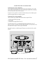
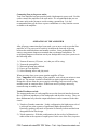
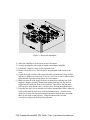
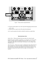
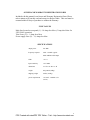
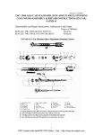
Rogue Audio Zeus
Vacuum Tube Dual Mono Power Amplifier
Owner’s Manual
Rogue Audio, Inc.
3 Marian Lane
Brodheadsville, PA 18322
ISSUE DATE: 05/17/10
1
PDF Created with deskPDF PDF Writer - Trial :: http://www.docudesk.com
TABLE OF CONTENTS
1) Introduction
3
2) Unpacking the Zeus power amplifier
3
3) Connecting Zeus to your system
4
4) Operation of the amplifier
5
5) Setting the tube bias
6
6) Troubleshooting
8
7) Registration card
9
8) Fuse values
9
9) Specifications
9
10) Warranty
10
2
PDF Created with deskPDF PDF Writer - Trial :: http://www.docudesk.com
INTRODUCTION
Congratulations on your purchase decision! We at Rogue Audio truly believe that
our amplifiers provide the “smartest” value in high-end audio. If you have never
owned a vacuum tube amplifier you will be thrilled by the silky-smooth sound
and incredible detail that only a tube amplifier can provide. And with the Zeus
amplifier, you can be sure that you are getting the very best in tube amplification.
We at Rogue Audio are extremely proud of our products and want you to enjoy
them to their fullest potential. So please, take the time to read through this short
manual so that you can be confident that you have set up your amplifier properly.
UNPACKING THE ZEUS POWER AMPLIFIER
Tools required: none
WARNING - This amplifier uses voltages that could cause injury or
death. Never open the amplifier while it is plugged in, and always wait
at least one hour after turning the unit off to unplug and open the unit.
Lethal voltages can remain in the electronics after the unit is
unplugged.
The Zeus amplifier has been painstakingly inspected for cosmetic flaws during
and after assembly. In order not to damage the cosmetic appearance of your
amplifier it is important that you follow the unpacking instructions carefully.
1. Carefully lift the outer box up and over the amplifier.
2. Remove the foam pads from the top of the amplifier
3. The Zeus has two built in handles on either end of the amplifier. Remove any
rings or jewelry that can scratch the aluminum finish. CAUTION – The
Zeus amplifier weighs 200 pounds. Carefully lift the amplifier and move it
to its operational location. Note – this is not a one person job!
4. Save the packing materials. The packing materials and box have been
carefully designed to protect your valuable equipment during shipping so you
don’t want to throw them away.
5. Align Tubes - Using a glove or a clean dry cloth, straighten any tubes that may
have tilted during shipment. Ensure that all of the tubes are fully seated in
their ceramic sockets.
3
PDF Created with deskPDF PDF Writer - Trial :: http://www.docudesk.com
CONNECTING ZEUS TO YOUR SYSTEM
Connecting Zeus to the Loudspeakers:
The rear panel has binding posts for both 4 and 8 ohm loudspeakers. The 4 ohm
taps are those located closest to the center of the amps rear panel. The 8 ohm taps
are located nearest the sides of the rear panel.
In general, if your speakers are rated at less than 6 ohms, use the 4 ohm taps and
use the 8 ohm taps if they are 6 ohms or greater.
Connecting Zeus to the preamplifier:
There are three types of input connections on the rear panel of Zeus:
1) Fully balanced XLR type input.
2) RCA input
3) Balance RCA input (labeled “low Z”)
For lowest noise levels, we recommend using either the balanced or “low Z’
inputs. If you have a preamp with a high output impedance you may choose to use
the standard RCA inputs to achieve proper bandwidth.
Note that if you have a variable output CD player you can drive the Zeus with it
directly.
Power in
8 ohm tap
4 ohm tap
XLR input
Low Z input
RCA input
Figure 1. Rear panel layout
4
PDF Created with deskPDF PDF Writer - Trial :: http://www.docudesk.com
Connecting Zeus to the power outlet:
Your Zeus amplifier has been provided with a high ampacity power cord. Use this
cord to connect the amplifier to the wall outlet. It is recommended that you use
the same outlet as the preamp to avoid creating a ground loop. It is also
recommended that you do not use a power conditioner as it may limit the current
available to the amplifier.
OPERATION OF THE AMPLIFIER
After all proper connections have been made, you are now ready to turn the Zeus
amplifier on. The power on/off switch is located on the front top of the amp
between the triode/ultralinear and standby switches. Some preamplifiers and
sources can generate dangerous transients that can damage loudspeakers. To
avoid letting dangerous transients reach your loudspeakers turn your system on in
the following order:
1)
2)
3)
4)
5)
Turn on all sources (CD, tuner, etc.) that you will be using.
Turn on the preamplifier.
Wait until preamp has stabilized.
Power up Zeus amplifier
Select listening source and play music
When powering down your system turn the amplifier off first.
Note – Important! After turning off the amplifier, wait at least one minute to turn
it back on. Do not turn it on then off and then on again in quick succession.
Doing this will not allow the power supply to discharge between on/off cycling
and may result in transient noises. If short term on/off cycling is necessary,
restart the amp in standby mode.
Triode/Ultralinear switch:
The output transformer of a tube amplifier acts as the electrical interface between
the very different impedances of the loudspeaker and the tube circuitry. There are
three fundamental ways that the output transformer can be connected to the tube
circuit.
1) Tetrode or Pentode connection – In this configuration, the highest power level
is achieved but at the expense of significantly higher distortion levels.
Practically speaking, this mode of operation is sonically inferior and has bean
disregarded in the Zeus design.
2) Triode connection – With this configuration, the lowest level of distortion is
achieved but at the expense of output power. In the case of the Zeus, its power
5
PDF Created with deskPDF PDF Writer - Trial :: http://www.docudesk.com
level in triode is high enough that it will likely provide plenty of power for
almost any speaker load.
3) Ultralinear operation – With this configuration, power levels near those of
tetrode mode are achieved with low distortion levels that approach those of
triode operation. For loudspeakers that demand very high levels of power,
ultralinear should provide excellent sound and plenty of power.
The triode/ultralinear switch allows the user to operate Zeus in either of the two
modes. In general, the sonic differences are subtle but for a given loudspeaker one
mode is likely to sound better than the other. There is a complex relationship
between the output transformer and the crossover network so try both and see
which one works best in your system. This switch can be operated while the
amplifier is playing but you will hear a small relay noise through the loudspeaker.
Standby Switch:
The Zeus amplifier SHOULD NOT BE LEFT RUNNING WHEN NOT IN
USE. Unlike solid state amplifiers, tube amplifiers should be shut down when
not being used. This will greatly prolong tube life.
A standby switch has been provided for short-term use between listening sessions
so that the amp will remain in a “warmed up “ state. If you will not be listening to
the amplifier for more than an hour, it is advised that the amplifier be turned off.
The standby switch lowers the voltage on the tubes and heater filaments to ½ of
normal operating voltage. Some output (distorted) will be heard so the source
material should be turned off when in standby mode.
SETTING THE TUBE BIAS
Tools required: bias tool (provided with amplifier)
The output tubes (the big ones) need to be “biased’ with a grid voltage that
controls the flow of electrical current through the tube. Tube biasing on the Zeus
amplifier has been designed to be both simple and effective. On some amplifiers
biasing is done for two or more tubes simultaneously. With this method, the total
current flowing through the group of tubes may be correct, but the current flow
through any individual tube may vary significantly from the optimal value. With
the Zeus amplifier the bias is set individually for each tube so that the correct
operating point is assured. An added benefit to this approach is that, should a
tube fail prematurely, the single tube can be replaced without having to purchase a
matched set. Use the following procedure to set the tube bias:
WARNING – There are dangerous and potentially lethal voltages inside this
amplifier. Do not touch any part of the amplifier other than as described
below. If you are uncertain about any of these instructions, please contact
your dealer and have them bias the amplifier for you.
6
PDF Created with deskPDF PDF Writer - Trial :: http://www.docudesk.com
Figure 2. Removable hatchplate
1)
2)
3)
4)
Allow the amplifier to warm up for at least 30 minutes.
Turn the preamplifier off so that no signal is entering the amplifier
Loosen the 4 captive screws on the top hatch cover.
Remove the hatch cover. The bias tool is snap attached to the inside of the
cover.
5) Locate the toggle switches and associated small potentiometers (they are blue
and have a small screw in the top). There is a set of six for each of the left and
right channels. Note the biasing meter for each channel
6) Make sure that all of the toggle switches are pointed towards the rear of the
amplifier. Begin with either channel and starting from the left, flip the first
toggle switch towards the front of the amplifier. You will see that the meter
will rise up to show that the tube’s current is now flowing through the meter.
7) Using the bias tool, slowly turn the screw on the potentiometer that is adjacent
to the switch until the bias meter reads 40 miliamps (mA). Turn the screw
clockwise to lower the bias and counterclockwise to raise the bias. Note that
there are two ends on the bias tool. Using the end with the recessed
screwdriver will greatly facilitate this operation.
7
PDF Created with deskPDF PDF Writer - Trial :: http://www.docudesk.com
Potentiometers
Switches
Figure 3. Bias switches and potentiometers
8) Flip the switch towards the rear of the amp thus disengaging the tube from the
meter circuit.
9) Repeat the above steps for each of the tubes in both channels.
As it is a quick operation, the tube bias should be checked on a regular basis.
TROUBLESHOOTING
Speaker Hum – If hum can be heard from more than a few inches from the
loudspeaker, there is probably a ground loop. Try using the “low Z” RCA jacks.
If there is still hum, flip the grounded/ungrounded switch on the rear panel to
ungrounded. If this fails to cure the hum, call customer service at Rogue Audio
for further advice.
Tube will not bias – If the meter provides a reading but the tube will not bias, the
tube is probably bad. If no meter reading can be attained, check the fuse (1/4
Amp slow blow). If the fuse is bad, replace the fuse and then set the bias. If the
bias will not maintain itself and the fuse blows again, the tube should be
replaced.
8
PDF Created with deskPDF PDF Writer - Trial :: http://www.docudesk.com
OWNER AND WARRANTY REGISTRATION FORM
Included with this manual is an Owner and Warranty Registration Form. Please
take a minute to fill out this card and return it to Rogue Audio. This card must be
returned within 30 days of purchase to validate the warranty.
FUSE VALUES
Main fuse located on rear panel (1) – 10 Amp slow blow (5 Amp slow blow for
220V-240V operation)
Tube Fuses (12) – ¼ Amp slow blow
Power supply fuses (2) – 1½ Amp slow blow
SPECIFICATIONS
output power
225 WPC
frequency response
10Hz - 100 kHz typical
20Hz-20KHz at full output
THD
< 0.1%
input sensitivity
1.0 V RMS
dimensions
19” W x 24” D x 12” H
weight
200 pounds (90Kg)
shipping weight
225lbs (101Kg)
power requirements
115/230V - 50/60Hz (15A
service)
9
PDF Created with deskPDF PDF Writer - Trial :: http://www.docudesk.com
LIMITED WARRANTY
Warranty Period
This product has been manufactured under the highest standards of quality and workmanship. Rogue Audio
Inc. (hereinafter “Rogue Audio”) warrants this product against defects in material or workmanship as
follows:
With the exception of vacuum tubes, Rogue Audio warrants to the original purchaser of this product all
parts of this product against defects in material and workmanship for a period of three years from the date of
retail purchase. Rogue Audio warrants the vacuum tubes for a period of six months from the date of retail
purchase. Any defective parts will be replaced free of charge, excluding shipping and handling.
Proof of purchase in the form of a bill of sale or recited invoice which indicates that the product is within
the warranty period must be presented to obtain warranty service. Rogue Audio suggests that the purchaser
retain the dealer’s bill of sale as evidence of the date of retail purchase.
What’s Not Covered
This warranty does not cover cosmetic damage or any damage that results from product misuse, product
abuse, installation error, connection to an improper voltage supply, accident, improper maintenance,
alterations, modifications not authorized in writing by Rogue Audio, lightening, power surges, or acts of God.
Use of any other than Rogue Audio factory parts may void this warranty.
This warranty does not cover the cost of parts and labor which would be otherwise provided without charge
under this warranty, obtained from any source other than Rogue Audio.
This warranty applies only to consumer use of this product and does not cover any product that is used in
any trade or business, or in an industrial or commercial application.
This warranty applies only to the original purchaser of this product when purchased from an
Authorized Rogue Audio dealer.
This warranty is valid only in the United States.
YOUR RIGHTS
ROGUE AUDIO LIMITS ITS OBLIGATIONS UNDER ANY IMPLIED WARRANTIES UNDER STATE
LAWS TO A PERIOD NOT TO EXCEED THE WARRANTY PERIOD. SOME STATES DO NOT
ALLOW LIMITATIONS ON HOW LONG AN IMPLIED WARRANTY LASTS, AND SOME STATES
DO NOT ALLOW THE EXCLUSION OR LIMITATION OF INCIDENTAL OR CONSEQUENTIAL
DAMAGES, SO THE ABOVE LIMITATIONS OR EXCLUSIONS MAY NOT APPLY TO YOU. THIS
WARRANTY GIVES YOU SPECIFIC LEGAL RIGHTS, AND YOU MAY HAVE OTHER
RIGHTS WHICH MAY VARY FROM STATE TO STATE.
To Obtain Service
To obtain service, you must contact Rogue Audio and obtain a return authorization number. The product
must be delivered to Rogue Audio in its original packaging prepaid at the following address:
Rogue Audio Inc.
3 Marian Lane
Brodheadsville, PA 18322
10
PDF Created with deskPDF PDF Writer - Trial :: http://www.docudesk.com