1
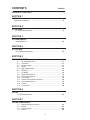
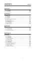
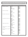
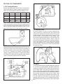
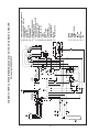
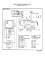
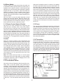
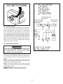
DIAGNOSTIC SERVICE MANUAL
AMERICANA & AMERICANA PLUS
RM 2351, RM 2354, RM 2451, RM 2454
RM 2551, RM 2554, RM 2652, RM 2662
RM 2663, RM2852, RM2862 & NDR1062
USA
SERVICE OFFICE
Dometic Corporation
2320 Industrial Parkway
Elkhart, IN 46516
574-294-2511
CANADA
Dometic Distribution
46 Zatonski Unit 3
Brantford, Ontario
CANADA N3T 5L8
519-720-9578
For Service Center
Assistance Call:
800-544-4881
Form No. 3311143.000 02/07
©2007 Dometic Corporation
LaGrange, IN 46761
Safety Instructions
Foreword
This service manual is the result of the dedication of The Dometic Corporation Technical staff
and its engineers in giving service people the
necessary instruction for making accurate analyses of certain conditions. Provided is a diagnostic chart leading a qualified mechanic into the
service manual pages to locate and solve symptoms which may occur. Dometic has continued
its commitment in providing service people with
this, the most up-to-date information about servicing Dometic RV accessories.
This manual has safety information and instructions to help users eliminate or reduce the risk
of accidents and injuries.
Recognize Safety Information
This is the safety-alert symbol. When you see this
symbol in this manual, be alert to the potential
for personal injury.
Follow recommended precautions and safe operating instructions.
Understand Signal Words
A signal word , WARNING OR CAUTION is used
with the safety-alert symbol. They give the level
of risk for potential injury.
Indicates a potentially hazardous situation which, if not avoided, could result
in death or serious injury.
Indicates a potentially hazardous situation which, if not avoided may result in
minor or moderate injury.
When used without the safety
alert symbol indicates, a potentially hazardous
situation which, if not avoided may result in property damage.
Read and follow all safety information and instructions.
CONTENTS
PAGE NO.
DIAGNOSTIC FLOW CHART............................................................................. 4
SECTION 1
OPERATION
Refrigerator Operation ....................................................................................6
SECTION 2
AC VOLTAGE
AC Voltage Requirements............................................................................9
SECTION 3
AC COMPONENTS
Heating Element .......................................................................................10
SECTION 4
DC VOLTAGE
DC Voltage Requirements ........................................................................10
SECTION 5
DC COMPONENTS
5.1
5.2
5.3
5.4
5.5
5.6
5.7
5.8
5.9
5.10 5.11
5.12 5.13
5.14
DC heating Element ...................................................................11
Thermistor ..................................................................................11
Solenoid Valve............................................................................11
Igniter .........................................................................................11
High Voltage Cable ....................................................................12
Electrode.....................................................................................12
DC Relay.....................................................................................12
Upper Circuit Board ....................................................................13
Lower Circuit Board ....................................................................13
Door Switch ................................................................................18
Climate Control Heater & Switch ................................................18
Low Ambient Switch ...................................................................18
Fuses..........................................................................................18
Thermofuse.................................................................................18
SECTION 6
LP GAS
LP Gas Requirements ..........................................................................19
SECTION 7
LP GAS COMPONENTS
7.1
7.2
7.3
7.4
Manual Gas Shut-Off Valve ........................................................19
Orifice .........................................................................................19
Thermocouple ............................................................................20
Burner ........................................................................................20
CONTENTS
PAGE NO.
SECTION 7
7.5 Flue Baffle.............................................................................................20 7.6 Flue Cap ..............................................................................................20
7.7 Flue Tube .............................................................................................20
SECTION 8
COOLING UNIT
8.1
8.2
8.3
8.4
8.5
8.6
8.7
8.8
8.9
Leveling..................................................................................................21
Ventilation...............................................................................................21
Air Leaks.................................................................................................23
Interior Liner Seal to Frame....................................................................23
Door Position..........................................................................................24
Ambient Temperature.............................................................................24
Cooling Unit............................................................................................25
Food Storage..........................................................................................26
High Humidity.........................................................................................26
SECTION 9
WIRING
9.1 Internal Wiring.......................................................................................26
9.2 External Wiring......................................................................................26
9.3 Wiring Schematics.................................................................................26
SECTION 10
ICE MAKER
10.1 Operation.............................................................................................26
10.2 Mold Heater.........................................................................................27
10.3 Ice Ejector............................................................................................27
10.4 Mold Thermostat..................................................................................27
10.5 Shut Off Arm........................................................................................27
10.6 Mold Switches.....................................................................................27
10.7 Timing Motor........................................................................................28
10.8 Water Valve.........................................................................................28
10.9 Ice Maker Replacement.......................................................................28
10.10 Water Fill Adjustment...........................................................................28
10.11 Water Supply........................................................................................29
10.12 Wiring Schematics..............................................................................29
This program will address the most common system problems associated with the RM2351, RM2354, RM2451, RM2454,
RM2551, RM2554, RM2652 ,RM2662,RM2663,RM2852and RM2862 refrigerators supplied by The Dometic Corporation.
Our intent is to provide you with a guideline of checks to make, should you encounter one of the following symptoms.
SYMPTOM
CAUSE
SECTION & PAGE
1.
No operation - no panel lights
Operation
DC Volts
Fuse
Wiring
Upper Circuit Board
Lower Circuit Board
1, page 06
4, page 10
5, page 18
9, page 26
5, page 13
5, page 13
2. No operation - has panel lights
Operation
DC Volts
Thermistor
Wiring
Lower Circuit Board
1, page 06
4, page 10
5, page 11
9, page 26
5, page 14
3. No AC operation - operates on gas mode
Operation
AC Volts
Fuse
Heating Element
Wiring
Lower Circuit Board
1, page 07
2, page 09
5, page 19
3, page 11
9, page 24
5, page 13
4.
No Gas operation - operates on AC mode
Operation
LP Gas
Manual Gas Valve
Igniter
High Voltage Cable
Electrode
Solenoid
Wiring
Lower Circuit Board
1, page 06
6, page 19
7, page 19
5, page 11
5, page 12
5, page 12
5, page 11
9, page 24
5, page 13
5.
Insufficient cooling on all modes.
Ventilation
Leveling
Ambient Temperature
Air Leaks
Thermistor
Cooling Unit
8, page 21
8, page 21
8, page 24
8, page 23
5, page 11
8, page 25
6.
Insufficient cooling on AC - cools properly
on gas mode.
AC Volts
Heating Element
Lower Circuit Board
2, page 09
3, page 10
5, page 13
7. Insufficient cooling on Gas - cools properly
on AC mode.
LP Gas
Orifice
Flue Baffle
Flue Tube
Burner
Lower Circuit Board
6, page 19
7, page 19
7, page 20
7, page 20
7, page 20
5, page 13
8.
Operation
Thermistor
Lower Circuit Board
1, page 06
5, page 12
5, page 14
Freezes.
SYMPTOM
CAUSE
SECTION & PAGE
9. Check light on
DC Volts
Wiring
LP Gas
Manual Gas Valve
Solenoid
Orifice
Burner
Thermocouple
Lower Circuit Board
4, page 10
9, page 26
6, page 19
7, page 19
5. page 11
7. page 19
7. page 20
7. page 20
5. page 13
10. Interior light on when door is closed
Wiring
Low Ambient Switch
Door Switch
Door Position
9. page 26
5. page 18
5. page 18
8. page 24
11. Rapid formation of frost
Food Storage
Interior Liner to Frame
High Humidity
Air Leaks
8. page 26
8. page 23
8. page 26
8. page 23
12. Water on frame
Interior Liner to Frame
High Humidity
Air Leaks
Climate Control Heater
8. page 23
8. page 26
8. page 23
5. page 18
SECTION 1
REFRIGERATOR OPERATION
DISPLAY PANEL RM2351, RM2451, RM2551, RM2652, RM2852
AUTO TEMPERATURE CONTROL
Refrigerator Control Panel
RM2652 & RM2852
RM2662 & RM2862
AMERICANA 2-WAY MODEL
1. Main Power Button ON/OFF
2. AUTO/GAS Mode Selector Button
RM2451 & RM2551
A. AUTO Mode indicator lamp
B. CHECK indicator lamp (Gas Mode
Only)
C. Climate control switch only on
RM2652 & RM2862
Travel Latch
RM2351
DISPLAY PANEL RM2354, RM2454, RM2554 RM2663 3-way
DISPLAY PANEL RM2662, RM2862 2-WAY
Refrigerator Control Panels
3-WAY
2-WAY
3-WAY
RM2454 & RM2554
Travel Latch RM2354
1. Main Power Button ON/OFF
2. DC Mode Selector Button
3. AUTO/GAS Mode Selector Button
4. Temperature Selector Button
A. DC Mode Indicator Lamp
B. AC Mode Indicator Lamp
C. GAS Mode Indicator Lamp
D. AUTO Mode Indicator Lamp
E. CHECK Indicator Lamp
(Gas Operation Only)
F. Temperature Indicator Lamps
2-WAY
1. Main Power Button ON/OFF
2. AUTO/GAS Mode Selector Button
3. Temperature Selector Button
B. AC Mode Indicator Lamp
C. GAS Mode Indicator Lamp
D. AUTO Mode Indicator Lamp
E. CHECK Indicator Lamp
( GAS Mode Only)
F. Temperature Indicator Lamps
OPERATION INSTRUCTIONS
OPERATION
Auto Thermostat
A. A continuous 12 volt DC supply must be available for
the electronic control to function.
B. Press the main power ON/OFF button (1) to
the DOWN position.
C. In AUTO mode, the AUTO lamp A will be illuminated.
The control system will automatically select between
AC and GAS operation with AC having priority. The
temperature is controlled by a factory preset temperature setting.
D. In GAS mode operation, no lamps will be illuminated
and the temperature is controlled by a factory preset
temperature setting.
IMPORTANCE OF LEVELING A
REFRIGERATOR
In an absorption refrigerator system, ammonia is liquefied
in the finned condenser coil at the top rear of the refrigerator. The liquid ammonia then flows into the evaporator
(inside the freezer section) and is exposed to a circulating flow of hydrogen gas, which causes the ammonia to
evaporate, creating a cold condition in the freezer. When
starting this refrigerator for the very first time, the cooling
cycle may require up to four hours of running time before the cooling unit is fully operational. The tubing in the
evaporator section is specifically sloped to provide a continuous movement of liquid ammonia, flowing downward
by gravity through this section. If the refrigerator is operated when it is not level and the vehicle is not moving, liquid ammonia will accumulate in sections of the evaporator
tubing. This will slow the circulation of hydrogen and ammonia gas, or in severe cases, completely block it, resulting in a loss of cooling. Any time the vehicle is parked for
several hours with the refrigerator operating, the vehicle
should be leveled to prevent this loss of cooling. The vehicle needs to be leveled only so it is comfortable to live in
(no noticeable sloping of floor or walls). When the vehicle
is moving, the leveling is not critical, as the rolling and
pitching movement of the vehicle will pass to either side
of level, keeping the liquid ammonia from accumulating in
the evaporator tubing.
OPERATION
Adjustable Thermostat
A. A continuous 12 volt DC supply must be available for
the electronic control to function.
B. Press the main power ON/OFF button (1) to the DOWN
position.
C. In AUTO mode, the AUTO lamp D will be illuminated.
The control system will automatically select between
AC and GAS operation with AC having priority. Temperature is selected by the user.
D. In GAS mode operation, the GAS lamp C will be illuminated and only operate on LP only. Temperature is
selected by user.
E. In DC mode, the DC lamp A will be illuminated and the
unit will only operate on DC until DC volts drops below
9.6 VDC.
OPERATION
Before starting the refrigerator, check that all the manual
gas valves are in the ON position. DO NOT forget the
manual shutoff valve on the rear of the refrigerator. This
refrigerator is equipped with a control system which can
be set to automatically select either 120 volt AC or LP gas
operation (AUTO mode), or if desired LP gas only (GAS
mode) or DC volts (DC Heater) where applicable.
Auto Thermostat
In both AUTO mode and GAS mode operation, the temperature is controlled by a factory preset temperature setting. The refrigerator controls will work down to 9.6 volt
DC.
Auto Mode
Press the AUTO/GAS button 2 (Auto Thermostat) or button 3 (Adjustable Thermostat) to the DOWN position. The
AUTO mode indicator lamp (A auto or D adjustable thermostat) will illuminate. If 120 volts AC is available, the
control system will select AC operation. If 120 volts AC is
not available, the control system will automatically switch
to GAS operation. Within 45 seconds the burner should
be ignited and operating normally. If the CHECK indicator
lamp (B auto or E adjustable thermostat) illuminates, the
control has failed to ignite the burner on GAS. To reset
when the CHECK indicator lamp, press the main power
ON/OFF button (1) to the OFF then ON position. Systems with the new lower control board are a three (3) try
system on gas. On the initial refrigerator start-up on gas
(120 volts AC is not available), it may take longer than 45
seconds to allow air to be purged from the gas line. If the
refrigerator has not been used for a long time or the LP
tanks have just been refilled, air may be trapped in the
supply lines. To purge the air from the lines may require
resetting the main power ON/OFF button (1) three or four
times. If repeated attempts fail to start the LP gas operation, check to make sure that the LP gas supply tanks are
not empty and all manual shutoff valves in the lines are
open.
Most LP gas appliances used in recreational vehicles are vented to the outside of the
vehicle. When parked close to a gasoline
pump, it is possible that the gasoline fumes
could enter this type of appliance and ignite
from the burner flame, CAUSING A FIRE OR
AN EXPLOSION.
FOR YOUR SAFETY, when refueling, shut
off all LP gas appliances which are vented
to the outside.
a period of approximately 45 seconds with two minutes (purge) interval after each trial. If unsuccessful, the
CHECK indicator lamp (B) will illuminate. To restart GAS
operation, press the main power ON/OFF button (1) to
the OFF and then ON position. The control system will
attempt a new ignition sequence. If the refrigerator has
not been used for a long time or the LP tanks have just
been refilled, air may be trapped in the supply lines. To
purge the air from the lines may require resetting the main
power ON/OFF button (1) three or four times. If repeated
attempts fail to start the LP gas operation, check to make
sure that the LP gas supply tanks are not empty and all
manual shutoff valves in the lines are turned on.
Note: Do not continue to reset GAS operation if the
CHECK indicator lamp continues to be illuminated after
several tries.
GAS Mode
Move the AUTO/GAS button 2 (Auto Thermostat) or button
3 (Adjustable Thermostat) to the UP position. The AUTO
mode indicator lamp (A) will go off. Within 45 seconds the
burner should be ignited and operating normally.
DC Mode 3 Way Units Only
Press the DC mode indicator button (2) to the DOWN
position. (Lamp [A] will light). Press the TEMPERATURE
SELECTOR button (4) until the lamp (F) at the desired
position is illuminated. The refrigerator will continue to operate in the DC mode until switch (2) is moved to the UP
position or control voltage falls below 9.6 VDC. The DC
mode overrides all the other operating modes. Discharging of the battery will occur if the vehicle engine is not
running.
Note: The DC mode is a holding mode not a full cooling mode. DC should be used once the unit is cooled
down and constant supply of DC available (driving
down the road).
DC Mode 3 Way Units Only
Press the DC mode indicator button (2) to the DOWN
position. (Lamp [A] will light). Press the TEMPERATURE
SELECTOR button (4) until the lamp (F) at the desired
position is illuminated. The refrigerator will continue to operate in the DC mode until switch (2) is moved to the UP
position or control voltage falls below 9.6 VDC.
The DC mode overrides all the other operating modes.
Discharging of the battery will occur if the vehicle engine
is not running.
Note: The DC mode is a holding mode not a full cooling mode. DC should be used once the unit is cooled
down and constant supply of DC available (driving
down the road).
To Shut Off The Refrigerator
The refrigerator may be shut off while in any mode of
operation by pressing the main power ON/OFF button to
the UP (OFF) position. This shuts off all DC power to the
control system.
Description Of Operating Modes
Auto Mode
To Shut Off The Refrigerator
When operating in the AUTO mode, the AUTO mode indicator lamp (A) will illuminate. The control system will
automatically select between AC and GAS operation with
AC having priority over GAS. If the control system is operating with AC energy and it then becomes unavailable,
the system will automatically switch to GAS. As soon as
AC becomes available again the control will switch back
to AC operation. Gas operation (120 volts AC is not available). The control system will activate the ignition system and will make three attempts to light the burner for
a period of approximately 45 seconds with two minutes
rest (purge) interval. If unsuccessful, the CHECK indicator lamp (B) will illuminate. To restart an ignition attempt
with the CHECK lamp illuminated or to clear (turn off) the
CHECK lamp, press the main power ON/OFF button to
the OFF position and wait a few seconds, then return to
the ON position. The control system will attempt a new ignition sequence. If 120 volts AC becomes available while
the CHECK indicator lamp is on, the CHECK lamp will not
turn off until the main power ON/OFF button is pressed
to the OFF then ON position but the unit will operate on
AC.
The refrigerator may be shut off while in any mode of
operation by pressing the main power ON/OFF button to
the UP (OFF) position. This shuts off all DC power to the
control system.
Limp Mode
This control system contains a feature where it will continue to operate the cooling system in event of a failure of
a major operating component. If the control cannot read
the temperature sensor and control to the preset temperature, then the control will run the cooling unit continuously at the energy source available. The refrigerator will
continue to operate in this mode indefinitely or until a new
sensor is installed and the system is reset.
SECTION 2 AC VOLTAGE
AC VOLTAGE REQUIREMENTS
This is an energized circuit. Shock can occur
if not tested properly. Testing is to be done
by a qualified service technician.
Gas Mode
When operating in the GAS mode, the AUTO mode indicator lamp (A) will be off. This mode provides LP gas operation only. The control system will activate the ignition
system and will make three attempts to light the burner for
a period of approximately 45 seconds with two minutes
The proper operating range is 100 to 132 volts. If voltage
drops below 100 volts, cooling efficiency will decrease
with voltage decrease.
The refrigerator will not switch to another mode of operation until all AC power is lost. The refrigerator is equipped
with a three-prong (grounded) plug for protection against
shock hazards, and should be plugged directly into a
properly grounded three-prong receptacle.
SECTION 4 DC VOLTAGE
DC Voltage Requirements
Clean Direct Current (DC) power is mandatory for hightech circuits to operate as designed. A battery will provide
straight line DC power. The converter and alternator produce DC power by a series of diodes that rectify alternating current to DC. The Dometic control system will only
tolerate up to 6 AC volts on the DC line. AC ripple can be
measured by a digital voltmeter set on the AC scale at the
main DC terminal block connections at the refer. Six volts
AC or less is acceptable. If AC volts exceed 6 on the DC
incoming line the power source should be cleaned up. AC
voltage in excess of 6 volts will affect the processor and
create erratic operation. When testing for AC ripple on the
DC line put a load on the converter. The operational range
of the unit is a minimum of 9.6V DC to a maximum of
22V DC. The unit will automatically shut down until voltage has decreased to 18V DC. The refrigerator requires
at least 9.6V DC for proper operation; however the panel
lights will continue to illuminate until voltage has dropped
to 4V DC or below. Do not use the body or chassis of
the RV as a substitute for either of the two conductors.
The refrigerator must be connected to the battery circuit
with two wires of adequate capacity to avoid voltage drop.
Proper polarity is crucial for refrigerator operation.
No other electrical equipment or lighting should be
connected to the refrigerator circuit. Just because you
can read volts does not mean you have the amps to operate the control system. If relays buzz, lights go dim or out
during operation, this could indicate there is a loose connection somewhere.
SECTION 3 AC COMPONENTS
Heating Element
The heating element is designed to deliver a predetermined amount of heat to the cooling unit. To check a heating element, remove the heater leads from the printed
circuit board and measure for proper resistance across
the two leads with a properly calibrated ohm meter. This
check is to be done with the heating element at room
temperature. You should obtain the following readings ±
10%:
Main Terminal Block
Model
WATTS
OHMS
AMPS
RM2351-4 175
80
1.5
RM2451-4 175
80
1.5
RM2551-4 175
80
1.5
RM2652
325
44
2.7
RM2662-3 325
44
2.7
RM2852
325
44
2.7
RM2862
325
44
2.7
Never over or under size the AC heater.
Grounds
The operation of the Dometic refrigerator is also dependent on good, clean ground connections. Loose or corroded ground terminals create an unknown resistance factor
that can affect the voltage detected by the Power Module.
A loose negative DC wire will create a negative millivolt
signal that the control board will pick up and create erratic
operation. Check the integrity of the grounds from the refrigerator all the way to the power source/battery. Clean or
tighten any suspicious looking connections.
Note: The DC terminal block below the control board
should be cleaned and tightened at the 4 wires.
10
SECTION 5 DC COMPONENTS
5.1 DC Heating Element
Remove the heater leads from the lower circuit board or
relay and measure for proper resistance across the two
leads. You should obtain the following readings ± 10%:
Model
Watts
Amps
Volts
Ohms
RM2354
150
12.5
12
.96
RM2454
175
15.0
12
.80
RM2554
175
15.0
12
.80
RM2663
215
18.0
12
.67
NOTE: The DC mode is a holding mode not a full cooling
mode. DC should be used once the unit is cooled down on
gas or AC and driving (constant supply of DC) down the
road. A continuity reading will indicate an open or complete circuit. Never over or under size the DC heater.
5.3 Solenoid Valve
Check the solenoid coil with a properly calibrated ohm
meter. Remove the connectors from the solenoid and
measure the resistance across the terminals. The proper
reading would be 49 ohms with tolerance range of ten
percent. Failure of the solenoid is very unlikely. Next,
hook up a manometer at the test port. Then check for DC
volts at gas valve terminals (Yellow + White -) while the
unit is in trial-for-ignition. If DC volts are present and pressure is low, replace the valve. If DC volts are not present
at the valve while the unit is in trial-for-ignition, verify that
the wire at Plug 3, Terminal 2 on lower circuit board has
DC volts (9 or more).
5.2 Thermistor
Disconnect the thermistor harness from the P2, 2-pin terminal on the lower circuit board. Place the thermistor in
a glass of ice water (more ice than water), approximately
33° F to 35° F. Wait 8 to 10 minutes. You should get a
reading of approximately 8,000 to 10,000 ohms. Always
test from the wire side as shown with the meter as not to
create a connection problem at the P2 connector.
5.4 Igniter
11
The igniter used on Dometic model refrigerators operates
on 12 volt DC. On gas operation the igniter senses the
resistance through the flame between the electrode and
burner. When there is no flame at the burner, the resistance is high and the igniter begins sparking to light the
burner. As soon as the flame is lit, the resistance between
the electrode and burner drops and the igniter stops
sparking. The resistance is monitored by the igniter, and,
if for any reason the flame goes out, the igniter begins
sparking until the burner is lit. The resistance between the
electrode and burner drops and the igniter stops sparking.
5.5 High Voltage Cable
If sparking starts during trial-for-ignition, the cable is good.
If there is no sparking during trial-for-ignition, disconnect
DC power at the refrigerator terminal block or switch unit
off. Disconnect high voltage cable from electrode. Reconnect DC power. If there is a sparking sound from the
igniter during trial-for-ignition, then replace high voltage
cable or electrode. On newer units the electrode and high
voltage cable are integrated into one component.
This is an energized circuit. Shock can occur
if not tested properly. Testing is to be done
by a qualified service technician.
This insures that the flame will always be lit when desired. First verify proper voltage at the positive (Yellow
+) and ground (Black –) terminals of the igniter. The reading should be within 1.5 volt of incoming voltage at the
main terminal block during trial-for-ignition. Next, remove
the high voltage cable from the igniter. The igniter should
produce a sparking sound during trial-for-ignition. If not,
replace the igniter. While operation is in the gas mode, the
power module and igniter are constantly monitoring the
presence of flame. If the flame is blown out, the reignitor
will immediately start sparking. When the power module
senses the loss of flame (thermocouple voltage below 13
MVDC) the 45 seconds trial for ignition period is started. The igniter installed on the refrigerators as original
equipment is part number 2931132019 (RV Gas Model
679). This igniter is rated 50 MA. This igniter may also be
used on any other model. When replacing the igniter always provide the product number for proper replacement.
DO NOT install the Channel Mark 6, Model 12 E igniter
(shown below) as a service replacement part. Installation
of the Channel Products, Inc., Gasliter Mark 6, Model 12
E, will VOID the Warranty on the refrigerator. To acquire
the proper igniter always provide the product number.
5.6 Electrode
Do a visual check for cracks or breaks on the ceramic insulator. A hair line crack can be hard to see at the electrode.
The spark gap must be set at three-sixteenths (3/16”) of
an inch and tip of electrode above the slots in the burner.
When adjusting always loosen the screw and move into
place, never try to move without loosing the screw. On
newer units the electrode and high voltage cable are integrated into one component. To acquire the proper part
always provide the product number.
5.7 DC Relay
The relay controls the circuit to the DC heating element. The load (amps) of the DC heating element goes
through the relay. Only used on newer 3 way units or
units that have the UNIVERSAL POWER MODULE KIT
(3308742.000) installed.
P3 Harness
Blue Wire
85
(+) 12 VDC
Heater Element Wire
87
30
Red Battery
Wire
86
P3 Harness
Blue Wire
Verify that the following components are good: upper circuit board, thermistor, 5 or 6 wire harness and 30/3-amp
fuses. In the DC mode Plug 3, Terminal 4 (positive 86)
and Terminal 3 (negative 85) should have voltage to close
the relay. If no voltage in the DC mode change the lower
board.
12
Wires from control board P3 harness to relay.
Terminal 85 P3-3 harness blue negative.
Terminal 86 P3-4 harness blue positive.
Wires to relay from DC source and DC heater.
Terminal 87 to DC heater positive.
Terminal 30 positive from DC power source.
If DC voltage to terminals 85 & 86, but no continuity between 30 & 87 the relay will need to be changed. Refer to
wiring diagram on the back of the product or check parts
list for proper diagram. To acquire the proper wiring diagram always use the product number.
5.9 Lower Circuit Board
WIRING Original style control 3 way & 2 way
Note: 2 Way will not have a J1 for DC heater
P1 To upper control board
P2 Thermistor
P3 To gas valve, igniter
J1 To DC heater
J2 To interior light and climate control
J3 Negative lead from thermocouple
J4 Positive 12V DC from terminal block
J5 AC line voltage (Black)
J6 AC neutral line (White)
J7 AC neutral out to AC heater
J8 AC line out to AC heater Switched side
J10 Positive lead from thermocouple
Thermocouple positive lead may be on the ground strip
on early units. Reference full wiring diagram next page.
5.8 Upper Circuit Board
With main ON/OFF switch on display panel in OFF
position: Check for DC voltage at Plug 1, Terminal 4
(orange wire +) positive and terminal 5 (red wire -)
negative DC on the lower circuit board. If no voltage,
then check fuse condition. Check for DC voltage between J4 positive and J10 negative terminals on the
lower circuit board (first generation) or J1 positive and
J10 negative on the current board (3850415013). If
no voltage on orange wire, fuse test OK and voltage
into lower control, replace the lower board. Next,
with main ON/OFF switch on check for DC voltage at
the upper circuit board between terminal 4 (orange
wire) and terminal 3 (red wire) which is negative (–)
DC. If no voltage and your previous check verified
voltage at the lower circuit board between the wires,
test and/or replace the cable assembly between the
upper and lower controls.
WIRING: Current style control 3/2 way, 2 way
will not have wires from P3 to external DC relay
Board part number 3850415013
P1 To upper control board
P2 Thermistor
P3 To gas valve, igniter and DC heater relay if 3 way
J1 Positive 12V DC from terminal block
J2 To interior light and climate control.
J3 To auxiliary fan (S.) and/or ice maker heat tape
J4 Negative lead from thermocouple
J5 AC line voltage (Black)
J6 AC neutral line (White)
J7 AC neutral out to AC heater
J8 AC line out to AC heater Switched side
J9 Positive wire from thermocouple
J10 Negative to Chassis ground
Note: Terminals 9 and 10 could be reversed as both terminals are ground on control board.
WIRING: Current style with integrated igniter
Board part number 3850712013
P1 To upper control board
P2 Thermistor
P3 To gas valve
J2 To interior light / climate control.
J4 Positive 12V DC from terminal block
J5 AC line voltage (black)
J6 AC neutral line (white)
J7 AC neutral out to AC heater
J8 AC line out to AC heater Switched side
J10 Negative to Chassis ground
Note: Units that have integrated igniter do not use a
thermocouple.
Upper Board Pin Connector Wire Location
13
WIRING ORIGINAL STYLE CONTROL 3 / 2 WAY, 2 WAY WILL NOT HAVE A J1 TO DC HEATER
14
15
S
T
N
B
U
O
BLACK
BROWN
RED
ORANGE
GREEN
7
6
7
6
Q
A
1
J7
3
J8
2
L N GND
9
2
J5
J1
P
P2
P1
WHITE
WHITE
J2
C
J6
J4
3308727.001
J3
J9
2
P3
2
J
2
YELLOW
WHITE
BLUE
BLUE
7
I
1
5
R
1
+ 12V DC
L
E
7
2
9
2
2
2
8
L
F
120V AC
K
D
4
G
M
H
12V DC
T
SWITCH
TERMINAL BLOCK
WHITE
1
1-- WHITE
2 BLACK
2-- BLACK
GREEN
3
3-- GREEN
4-- GREEN/YELLOW
4 GREEN/YELLOW
5-- GRAY
GREY
5
6-- BROWN
6 BROWN
7-- BLUE
BLUE
7
8-- YELLOW
8 YELLOW
9-- RED
9
RED
U
A---CIRCUIT
BOARD
POWER
CIRCUIT
BOARD
POWERMODULE
MODULE
A
B---CURCUIT
BOARD
DISPLAY
B CIRCUIT BOARD DISPLAY
C---THERMISTOR
THERMISTOR
C
D---REIGNITER
D GAS VALVE
F---THERMOCOUPLE
REIGNITER
E
G---ELECTRODE
F THERMOCOUPLE
H---RETAINER FOR BURNER
ELECTRODE
G
I--- TERMINAL BLOCK
H RETAINER FOR BURNER
J--- GROUND TERMINAL STRIP
TERMINAL BLOCK
I
K--- ABSORPTION UNIT
J GROUND TERMINAL STRIP
L--- HEATER 120V AC
ABSORPTION UNIT
M--KHEATER 12V DC
L HEATER 120V AC
N-- LIGHT
HEATER 12V DC
O--MSWITCH
LIGHT
N
P-- FUSE 3
AMP
Q-- OFUSE SWITCH
5 AMP
FUSE 3ARELAY
R-- DCPHEATER
FUSECABLE
5A
Q
S-- HEATING
R DC HEATER RELAY
T-- SWITCH
HEATING
CABLE
U-- STERIMAL
BLOCK
CURRENT CONTROL SYSTEM WIRING 2 WAY WILL NOT HAVE DC RELAY & HEATER
Part number 3850415013
J10
WIRING INTERGRATED IGNITER CONTROL
Part number 3850712013
16
Lower Board Testing
ALL TESTS ARE TO BE DONE WITH THE REFRIGERATOR IN THE COOLING MODE.
The millivolts meter should read between 25 to 35 millivolts with the gas flame burning. When the power module
senses the loss of flame (thermocouple voltage below 13
MVDC) the 45 seconds trial for ignition period is started.
Turning the refrigerator OFF–ON while operating in the
gas mode may cause a check light.
DC Volts
Note: A loose ground will create erratic or no
gas operation on all systems.
Unplug the thermistor from the control board during
lower board testing to assure unit is calling for cooling.
Measure volts between terminal J4 positive (early control)
and the ground and integrated igniter board. Current control board J1 positive and ground. Voltage should be the
same as at the positive (+) and negative (–) on DC input
terminal block. 9.6 min to 22 max would be the operating
range. Refer to wiring diagram on the product number unit
you are currently working on. If voltage outside the 9.6 to
22 range, check power supply, terminal block and correct
power source before going on with the test.
Gas Mode Integrated Igniter
Verify that the following components are good: upper circuit board, electrode with cable, wire harness and 3-amp
fuse. Units that have integrated igniter do not have a thermocouple. The igniter senses the flame thru the electrode
and communicates with the lower main control. The integrated igniter used on certain Dometic model refrigerators
operates on 12 volt DC thru the control board. On gas
operation the igniter senses the resistance through the
flame between the electrode and burner. When there is no
flame at the burner, the resistance is high and the igniter
begins sparking to light the burner. As soon as the flame
is lit, the resistance between the electrode and burner
drops and the igniter stops sparking. The resistance is
monitored by the igniter, and, if for any reason the flame
goes out, the igniter begins sparking until the burner is lit.
This insures that the flame will always be lit when desired.
The integrated ignition system is also a three try control.
Turning the refrigerator OFF–ON while operating in the
gas mode may cause a check light. If you have voltage to
the gas valve during trial-for-ignition but no spark and
the electrode with cable checks good, change the lower
control board.
AC Mode
This is an energized circuit. Shock can occur
if not tested properly. Testing is to be done
by a qualified service technician.
Test upper control board and harness between upper
and lower before testing lower for proper AC operation.
Check that incoming AC voltage is present at terminals
J5 (black) and J6 (white) on the circuit board. With unit on
AC operation, check for voltage at the heating element
connection terminals J7 and J8 on the circuit board. If no
voltage is present, check the 5 amp AC, 3 amp DC fuses,
wiring harness and upper control. If AC volts are present
at J5 and J6 and no voltage on J7 and J8 the AC voltage
detection circuit is damaged and the control board will
need to be changed.
Note: Never engage the gas mode with the electrode cable unplugged from control board. This will
damage the igniter on the board.
DC Mode 3-Way Units
Gas Mode
Verify that the following components are good: upper circuit board, wire harness, DC heater and 3/30 amp DC fuse
and relay. With the DC mode selected on the upper control, v erify voltage between terminals J4 positive and the
ground strip early control or J1 positive current control and
J10 negative is above 9.6 min. When the DC heater is activated it will draw approximately 12 to 18 amps and if the
power source is weak the control voltage will drop below
proper operating range and shut down. Check for DC volts
from J1 (positive) early control to DC heater, if no DC volts
change the control board. On late controls (3850415013
& 3850712013 [integrated igniter]) the DC heater load
(amps) goes through a stand alone relay. In the DC mode
Plug 3, Terminal 4 (positive) and Terminal 3 (negative)
should have voltage to close the relay. If you have voltage coming in with unit in DC mode but nothing out to
DC heater or relay, change the control board. Refer to wiring diagram on the back of the product or check parts list
for proper diagram. To acquire the proper wiring diagram
always use the product number.
Note: All current Dometic control boards are 3
try systems in the gas mode. There is a 2 minute purge cycle between each trial for ignition.
Flame failure will take 6 to 7 minutes.
Verify that the following components are good: upper circuit board, thermistor, wire harness and 3-amp fuse. First,
check for voltage during trial-for-ignition at Plug 3, Terminals 1 (white Wire -) and 2 (yellow wire +) to the igniter
and solenoid. If no voltage is present change the circuit
board. If voltage is present, check for voltage at the igniter
and solenoid. If no voltage is present, check the wires. To
check the flame sense circuit of the lower circuit board,
operate the refrigerator on GAS and measure the millivolts between J3 (NEGATIVE) terminal original control or
J4 current control and the other wire (POSITIVE) connection from the thermocouple.
17
5.10 Door Switch
When the low ambient control is turned on it by-passes
the interior light switch and turns on the interior light. The
heat load of the 10 watt light bulb will cause the cooling
unit to cycle approximate every 35 to 55 minutes. This will
help keep the temperature in the freezer in the freezing
zone. In low ambient temperatures the freezer will warm
up because the refer box will not call for much cooling.
When the refer calls for cooling it will cool the freezer first
and then cool the refer box. When it is cool outside the
refer box won’t call for as much cooling and the freezer
might warm up to normal food storage temperature (34
to 35). The second thing the control will do is keep the
cooling unit from freezing up in low outdoor temperatures.
(20 to 0 F)
5.11 Climate Control Heater & Switch
5.13 Fuses
The door switch is an open switch when the switch arm
is depressed (interior light should be off). When the refrigerator door is open the switch is closed (interior light
should be on). Check that the switch assembly is properly
aligned and that it is not broken. Check the switch assembly for continuity. To do a continuity check, first be
sure all power is disconnected or OFF to the refrigerator.
Second, remove all wires from the switch assembly, then
check the switch.
After the check, be sure the switch assembly is wired
properly per the wiring diagram. When the switch is depressed, there should not be continuity. When the switch
is NOT depressed, there should be continuity. If any of
these checks are incorrect, replace the switch.
Not used on all units. Disconnect the wires from the
switch and do a continuity check. In the OFF position,
there should be no continuity. In the ON position, there
should be a continuity reading. To check the heater itself,
perform an ohms resistance reading on the heater wire by
using a properly calibrated ohm meter. From the side of
the switch that only has two wires, with switch off take an
ohms reading to ground. The proper ohms reading will be
24 ohms ± 10%. The approximate amp draw is less than
.5 (1/2) amp.
The 3 amp DC fuse is designed to protect the circuit board
from internal/external DC shorts. The 5 amp AC fuse is
designed to protect the integrity of the AC detection and
heater circuit from shorts. On 3-way models only, the 30
or 35- amp DC fuse is designed to protect the DC heater
circuit integrity. All fuses can be checked for continuity. If
a fuse blows don’t replace it until the problem has been
found. If a fuse blows there is a short or component that
has created the problem.
Function
5.14 Thermofuse
During the summer months of high temperatures and
humidity, the metal frame between the freezer and fresh
food compartments may have water droplets forming. The
number of water droplets will increase if the vehicle isn’t
air conditioned during these months. Some refrigerators
come standard with a 12 volt (DC) climate control that
will evaporate the water droplets when they form. To have
the climate control on, you position the switch (normally
located beneath the top decoration panel that houses the
control panel) to ON. The approximate amp draw is less
than .5 (1/2) amp.
Newer and replacement cooling units have a Thermofuse
located on the boiler. The function of the thermofuse is
to shut down the control system in the event the cooling
unit has a problem. On certain units the fuse can be reset
by pushing the button in the center. The thermofuse is a
non-replaceable component of the cooling unit. When the
fuse pops it is normally an indication the cooling unit has
a problem and the cooling unit will have to be replaced.
The fuse can be checked for continuity .
Note: The climate control will draw 12 volt DC power
continuously when in the ON position on certain models.
It should be turned OFF when a charging source is not
available or unit is in storage.
5.12 Low Ambient Switch
Not used on all units. Disconnect the wires and do a continuity check. In the OFF position, there should be no
continuity. In the ON position, there should be a continuity reading. All RV absorption refrigerators, while similar,
operate a little differently than your home refrigerator. Dometic designers and engineers have equipped your refrigerator with an exclusive feature that allows for troublefree operation in low ambient temperature ( below 50° F)
for extended periods of time. Simply turn on the low ambient switch located beneath the top decoration panel that
houses the control panel. Once the outdoor temperature
is above 50° F, the low ambient switch should be turned
off.
18
SECTION 6 LP GAS REQUIREMENTS
6. No bubbles should appear at the opening of the burner
jet orifice. The presence of bubbles indicates a defective
gas safety shutoff, and service is required.
7. If no bubbles were present at the burner jet orifice, it
should be rinsed with fresh water. Be careful not to damage the burner jet orifice. Replace cover and press the
main power ON/OFF button (1) OFF and back ON. Normal operation of the burner should return. Allow the burner to operate for a minimum of five minutes.
DO NOT use a flame to check for gas
The LP gas pressure to the refrigerator should be 11 inches water column with half of all BTU’s of the RV turned
on. With all other appliances off, the pressure to the refrigerator should not exceed 12 inches water column. To
check the gas pressure when the refrigerator is operating,
there is a pressure test port below the solenoid valve assembly.
7.2 Orifice
The Dometic orifice is a brass alloy with a man-made ruby
pressed in the center that has been laser-beam drilled in
a spiral pattern. The orifice is cleaned by using an alcohol
based solvent. Soak the orifice for approximately 1 hour
and allow to air dry. Don’t insert anything in the center of
the orfice it will harm the man-made ruby. Don’t use an
air nozzle to blow thru the orifice as the ruby could be
moved. Never over or under size the orifice on a Dometic
refrigerator. The cooling unit is designed to work with a
predetermined amount of heat and modifying the orifice
size will decrease cooling. If there is a lack of cooling on
gas operation, verify the orifice is the proper size per the
chart .
SECTION 7 LP GAS COMPONENTS
7.1 Manual Gas Shutoff Valve
The manual shutoff valve is a non-serviceable part. The
valve is part of the solenoid valve assembly. It is very rare
to have problems with the manual shutoff or the solenoid
assemblies. If you have checked gas pressure and it is
low, check pressure at input line to refer. If pressure is 11
inches at input and low at the pressure test port, change
solenoid valve assembly. The valve is not opening all the
way.
TESTING LP GAS SAFETY SHUTOFF
The gas safety shutoff must be tested after the refrigerator is connected to the LP gas supply.
To test the gas safety shutoff, proceed as follows:
1. Start the refrigerator according to the instructions, and
switch to GAS mode.
2. Check that the gas flame is lit and the GAS mode indicator lamp is on.
3. Close the manual gas shutoff valve at the back of the
refrigerator.
4. Wait for one minute for units prior to 2003 and six to
seven for units after 2003 (Three Try Board). The CHECK
indicator lamp should be on and the GAS mode indicator
lamp should be off.
5. Remove protection cover from burner and open the
manual gas shutoff valve. Do not change any button positions on the control panel. Apply a non-corrosive commercial bubble solution to the burner jet orifice.
DO NOT use a wire or pin when cleaning the burner
jet as damage can occur to the precision opening.
This can cause damage to the refrigerator or create
a fire hazard.
MODEL
RM2351-4
RM2451-4
RM2551-4
RM2652
RM2662-3
RM2852
RM2862
19
JET SIZE
#39
#43
#43
#58
#58
#58
#58
Always check the parts list with the model and product
number to assure the right jet size.
7.3 Thermocouple
MODEL
The Thermocouple is a component that extends over
the burner assembly so its tip is in the path of the flame.
During normal gas operation, the thermocouple should
produce 25 to 35 millivolts when connected to the lower
circuit board. Any reading below 18 millivolts could cause
erratic gas operation. Note: A reading of 18 or less could
be caused by low gas pressure, carbon build up or improper thermocouple location. The thermocouple should
be centered over the burner and extend over 3 slots. The
control board reads negative millivolts from the thermocouple and the positive lead goes to the ground terminal
on the control board or ground strip.
Note: A rapid on/off of the switch or a brief interruption of
DC power source does not allow the thermocouple time
to cool. When the power is restored, the thermocouple
has not cooled completely and the check light may come
on. Turning the refrigerator OFF–ON while operating in
the gas mode may cause a check light. The new lower
control has built-in delay when the unit is first turned on.
If the lower control reads millivolts in excess of 6 MVDC
the control will go into a 30 second gas delay before attempting to light on gas. To test the thermocouple set the
meter to DC millivolts. Put the black lead from the meter
to terminal J3 ( original board ) or J4 ( current board ) and
the red lead from the meter to J10 or other lead from thermocouple. Start the unit on gas and measure the DC millivolts produced by the thermocouple. The thermocouple
should produce 22 to 36 millivolts within 45 seconds. If
the millivolts are 20 or below erratic operation will occur.
Anything below 10 to 13 the control board will not keep
the gas valve energized and turn on the check light after
the 45 second trial-for-ignition.
RM2351-4
RM2451-4
RM2551-4
RM2652
RM2662-3
RM2852
RM2862
ABOVE
BURNER
1-15/32
1-15/32
1-15/32
1-7/8
1-7/8
1-7/8
1-7/8
SIZE
3-15/16X25/32
3-15/16X25/32
3-15/16X25/32
5-1/8X13/16
5-1/8X13/16
5-1/8X13/16
5-1/8X13/16
Lack of heat transfer to the cooling unit will cause low cooling performance in the gas mode. It should be cleaned
periodically, at least once a year. The proper position of
the baffle above the burner should be as shown in the
chart : Always refer to parts list on the model/product
number unit you are currently working on.
7.6 Flue Cap
The flue cap is located at the top of the flue tube and is
attached with a screw or pushed down over tube. Not all
units will come with a flue cap. The design of the baffle
wire in the flue tube will slow down a down draft.
7.7 Flue Tube
Carbon build up will not allow the heat transfer to the cooling unit and cause lack of cooling on gas. The flue tube is
welded to the boiler of the cooling unit. In a rough riding
coach there have been rare cases where the weld will
crack and create lack of cooling. The flue tube must be
cleaned periodically, at least once a year. Clean by using
a flue brush, Dometic Part No. 0151404001.
7.4 Burner
The slots in the burner should be directly below the flue
tube. The burner should be cleaned periodically, at least
once a year. Soak the burner in an alcohol based solvent
and allow to air dry. If the burner does not have a good
ground it can cause erratic gas operation. The electrode
sparks to the burner tube and a erratic ground will cause
erratic gas operation.
7.5 Flue Baffle
The flue baffle ( spiral baffle ) is a twisted piece of metal
that hangs in the flue tube to slow the heat from the flame
to the proper location on the cooling unit. If the flue baffle
is too high or low the heat will not be transferred to the
cooling unit properly.
Baffle
20
SECTION 8 COOLING UNIT
8.1 Leveling
Typical Roof Vent and Side Wall Vent
Leveling is one of the requirements for proper operation
of absorption refrigerators. The absorption design utilizes
no mechanical pumps or compressors to circulate the refrigerant within the system, so proper leveling must be
maintained to provide the correct refrigerant flow. Without proper leveling, refrigerant within the cooling unit will
collect and stagnate at certain areas. Without proper refrigerant flow, the cooling process will stop. Absorption
refrigerators have a type of cooling unit that utilizes an enclosed pump tube surrounded by a solution to protect the
assembly. To ensure proper leveling, the vehicle needs
to be leveled so it is comfortable to live in. (No noticeable
sloping of floor or walls). When the vehicle is moving, leveling is not critical as the rolling and pitching movement
of the vehicle will pass to either side of level, keeping the
refrigerant from accumulating in the piping
BAFFLE
PERFECTLY LEVEL NOT REQUIRED
MORE LEVEL = BETTER OPERATION
8.2 Ventilation
The installation shall be made in such a manner as to
separate the combustion system from the living space of
the mobile home or recreational vehicle. Openings for air
supply or for venting of combustion products shall have a
minimum dimension of not less than 1/4 inch. Ventilation
is a critical requirement for proper cooling unit operation.
The coach vent system must be able to provide a way to
direct the hot air, produced by the action of the cooling
unit, out away from the installation of the refrigerator. The
refrigerator extracts heat from the interior of the refrigerator cabinet and dissipates the heat out through the vent
system. In a proper installation there should be zero (0”)
clearance surrounding the sides and top of the refrigerator to achieve proper air flow. Clearance from the back of
the refer to the outside wall must be kept less than 1 inch.
All potential dead air pockets should be blocked or baffled
to ensure that heat won’t be trapped in these spaces and
reduce efficiency.
Note: Refrigerators should be installed in accordance
with appropriate installation instructions received with the
refrigerator.
FOR MORE UPDATED INFORMATION ON UNIQUE
VENTILATION REQUIREMENTS, refer to Vent Installation Instructions, Form No. 3308666.XXX.
Typical Two Side Wall Vents
TURNING
VANE
BAFFLE
21
Typical Two Side Wall Vent Application. Always
Refer To Vent Instructions 3308666.xxx
22
8.3 Air Leaks
8.4 Interior Liner Seal To Frame
Check the gasket on the doors to be sure of a positive
air seal. A simple method to check gaskets is to close
the door on a dollar bill, then pull the dollar bill out. If no
resistance is felt, the gasket in that place is not sealing
properly. This should be done on all four sides of the door
in several places. If a gasket is not sealing properly, lift
up inside of door gasket and insert 1/4” ball of fiberglass
insulation at all four corners on both doors. This is especially important to the top corners. Next warm the gasket
material with a hair dryer. Then close the door and the
magnetic strip should pull the gasket to the metal frame.
Leave door closed until the material has cooled. Then
recheck for a positive seal. If a positive seal cannot be
achieved, replace the door gasket. Also check that the
cooling unit is installed properly. The cooling unit’s foam
block, the portion that surrounds the evaporator coils,
must be flush to the cabinet at the back of the refrigerator
and have a positive seal. If the cooling unit is not installed
properly, remove and install properly.
Note: Air leaks will cause insufficient cooling as well as
rapid formation of frost.
There is a seal that is applied to the liner in the area
where the metal frame makes contact with the interior
liner. If this seal is incomplete, cold air can migrate out to
the metal frame. If this happens, condensation could form
on the frame and could promote rapid formation of frost.
If you suspect an improper seal, apply a small bead of
silicone all the way around the perimeter where the frame
meets the interior liner. Next remove all screws securing
the refrigerator into the cabinet and slide the refrigerator
out approximately 2–4 inches. Clean the metal frame and
foil-backed insulation around the refrigerator. Apply a foilbacked adhesive tape to the joint between outer frame
and foil-backed refrigerator insulation. Make sure the
refrigerator is dry and that the surface temperatures are
above 50° F. Use a clear silicon caulking compound and
seal the seam between the refrigerator’s plastic liner and
the metal frame. Apply the silicon in a continuous bead
around both the refrigerator freezer and food compartments.
CAULK SEAM BETWEEN
PLASTIC LINER AND
METAL FRAME
(Refrigerator
shown with doors
removed)
DO NOT OVERHEAT
AS YOU CAN MELT THE MATERIAL
Another source for an air leaks could be the drain hose.
When units are installed, there is a check valve at the end
of the drain. At install the hose might be shortened and
the check valve must be moved to the end of drain hose.
Any time lack of performance or excessive frost is experienced, look for the check valve at the end of hose.
APPLY FOIL-BACKED OR ALUMINUM
TAPE TO JOINT BETWEEN OUTER
FRAME AND FOIL-BACKED REFRIGERATOR INSULATION. GO AROUND
THE COMPLETE FRAME.
23
Note: To form a proper seal, it is important not to leave
any gaps.
8.5 Door Position
If the upper or lower door is closing too high or low against
the frame, cold air leakage can occur. Adding or deleting
a flat thin washer on top of the lower or middle hinge pin
can raise or lower the door position. To correct the door
alignment, loosen the hinge screws slightly and reorient
the door in the proper position. Hold the door in its new
position and carefully retighten the hinge screws.
8.6 Ambient Temperature
This is the temperature surrounding the recreational vehicle, as well as the temperature of air at the back of the
refrigerator. As the ambient temperature increases, the air
temperature in the area of the cooling unit increases. Improper venting at this point will cause the cooling unit to
have reduced efficiency. A refer that chases the out-side
temperature is improperly vented or has a weak cooling
unit.
24
25
SECTION 9 WIRING
9.1 Internal Wiring
8.7 Cooling Unit
The cooling unit is a self-contained, hermetically sealed
set of coils where the refrigeration process takes place.
The chemicals involved in the cooling process include
hydrogen, ammonia, water and a rust inhibiting agent.
There are no repairs recommended on the cooling unit.
If it is defective, replace with a new cooling unit. To check
the cooling unit, first verify the AC heating element is
good, proper ohms at room temperature, proper venting
and unit is level. Then place approximately one gallon of
water inside the refrigerator and place a thermometer in
one of the containers of water. Next, unplug the thermistor from the lower control board. This will by-pass the
thermostat control and operate for at least 12 hours. Then
check the temperature on the thermometer. It should be
at 43 degrees or lower depending on test conditions. If so,
the cooling unit is good. If the temperature of the water is
above 43 degrees, replace the cooling unit. The outside
temperature will affect the cooling capacity of the unit.
There is that rare occasion when the cooling unit will work
OK for the first 12 hours and then start to warm up. If the
customers complaint is “works OK for 2 to 5 days and
then warms up” the unit may have an internal problem. To
test this it would be necessary to operate the cooling unit
for up to 24 to 48 hours in the test mode.
Check all wires and the connectors to ensure a proper
and tight connection. Also verify the refrigerator is wired
per the wiring diagram for the model you are working on.
(See applicable wiring diagrams for your model refrigerator). A loose connection can create erratic operation. Always check the wires at the DC terminal block, two wires
in and two wires out.
9.2 External Wiring
120 Volts AC Connection: The refrigerator is equipped
with a three prong (grounded) plug for protection against
shock hazards and should be plugged directly into a properly grounded three prong receptacle. DO NOT cut or remove the grounding prong from this plug.
12 Volt Connection : The connection is made to the terminal block marked 12 volts DC. The control system is
connected to a battery/converter circuit and could draw
about 3 amps at 12 volts DC. The refrigerator must be
connected to the battery circuit with two wires of adequate
capacity to avoid voltage drop. Proper polarity is crucial
for refrigerator operation. Don’t use the chassis for the
ground circuit. No other electrical equipment or lighting should be connected to refrigerator circuit. A loose
connection will create erratic operation.
On three way units the DC heater will draw up to 18
AMPS and size of wires should follow installation instructions for the model unit you are working on.
8.8 Food Storage
Proper refrigeration requires free air circulation within the
food storage compartment. Restricted air circulation within
this compartment will cause higher cabinet temperatures.
To remedy this situation, simply rearrange your foodstuffs.
It is also essential that the shelves are not covered with
paper or large storage containers. Always remember to
allow for proper air circulation. Odorous or highly flavored
foods should always be stored in covered dishes, plastic
bags or wrapped in foil or waxed paper to prevent food
odors. Vegetables, lettuce, etc., should be covered to retain their crispness.
9.3 Wiring Schematics
To view typical wiring schematics look in the Lower Circuit
board testing section 5, pages 14, 15 and 16. All units
should have a specific schematic on the rear of that unit.
To acquire the proper one always have the product number when you call or e-mail.
SECTION 10 ICE MAKER
10.1 Operation
The refrigerator must be allowed to precool properly before starting the ice maker. The refrigerator has to be connected to 120 volts AC before the ice maker can operate.
The water line manual shutoff valve (not part of Dometic
unit) must be open. To start making ice, move the ice level
bail arm to DOWN position.
NEVER PUT HOT FOOD INTO THE REFRIGERATOR.
To reduce frost formation in and on the freezing compartment, cover stored liquids and moist foods and do not
leave the door open longer than necessary. When the
refrigerator is heavily loaded, it takes a longer time for
refrigerator temperatures to lower, also increasing the ice
making time. A very heavy load may also cause defrosting. Defrosting every 7 to 21 days would be normal, depending on the humidity level.
8.9 High Humidity
High humidity may cause a small amount of condensation
to form on the frame of the refrigerator. In some cases it
can develop to such a degree that it will run off the frame.
As the humidity is reduced, the sweating will decrease.
High humidity can also be a factor in rapid formation of
frost.
26
10.4 Mold Thermostat
When the ice maker thermostat senses the preset temperature for ejection of the ice cubes, the fingers will start
to rotate, dumping any ice cubes and filling the mold with
water. When the storage container is full of ice, the ice
level bail arm cannot return to the DOWN position. This
will stop further production of ice until the container is
emptied and the bail arm is returned to the down position.
The absorption system will keep the compartment at the
proper temperature for storage of ice. Ice making is accelerated if the thermostat is set to the coldest position. It
is a good idea to do this a few hours before you anticipate
a need for ice. The first few cycles may have small cubes
due to air trapped in the water lines. The first container of
ice cubes should be dumped if the water system has been
winterized or not used for several weeks.
This is a single-pole, single-throw, bimetal switch. It starts
an ejection cycle by closing at 15º F ± 5º. The reset temperature is 50º F ± 5º. The thermostat is in series with the
mold heater and acts as a safety against overheating in
case of a mechanical failure. If the thermostat is defective, replace it. The mold thermostat starts the ice ejection
cycle. The freezer must be down to proper temperature
for the mold thermostat to start the cycle. The cycle can
be started by turning the large gear clock wise 1/8 to 1/4
of a turn.
Note: if the ice maker was cleaned and drained, no ice
cubes will be dumped into the storage container during
the first few cycles.
10.2 Mold Heater
The mold heater uses 165 watts to thaw the ice free from
the mold. It is wired in series with the thermostat which
also acts as a safety device. With power to the appliance off, check for resistance between the two leads to
the heater element. You should obtain a reading of approximately 80 ohms +/- 10%. If the heater is found to be
defective, the manufacturer recommends replacement of
the entire ice making unit for proper operation.
10.5 Shut Off Arm
The shutoff arm is cam driven. It operates a switch to control the quantity of ice produced. During the ejection cycle
the arm is raised and lowered during each of the two revolutions of the timing cam. If the shutoff arm comes to rest
on top of the ice in the storage bin during either revolution,
the switch will remain open and stop the ice maker at the
end of that revolution. The arm has a manual shutoff built
into the linkage; by raising the arm as high as possible, it
will lock in that position until forced down. If the arm and
switch do not operate properly, check for damage and repair or replace parts as necessary.
10.3 Ice Ejector
The ice ejector blades sweep the ice from the mold cavities during the ejection cycle. The drive end of the ejector
is “D” shaped for positive coupling. The bearings at both
ends are lubricated with silicone grease. If the ejector
blades are frozen into the ice, defrost the ice maker and
manually cycle the ice making unit, making sure the ejector stops at the right location.
10.6 Mold Switches
The three switches are single-pole, double-throw style.
They are identical and interchangeable. The holding
switch assures completion of a revolution once a cycle
has started. The water valve switch opens the water
valve during the fill stage of the cycle. NOTE: This is the
only adjustable component of the ice maker. If you use a
double throw switch, DO NOT use the N.O. terminal. The
shutoff switch stops the ice maker’s operation when the
storage bin is full.
27
10.9 Ice Maker Replacement
This is an energized circuit. Shock can occur
if not tested properly. Testing is to be done
by a qualified service technician.
10.7 Timing Motor
This is a low-wattage, stall-type motor which is geared to
the timing cam and ice ejector. It is a one RPM motor. To
check the motor, disconnect power to the appliance and
test for continuity between the two leads. If you DO NOT
have continuity, replace the motor. If you have continuity
and the motor runs, DO NOT replace.
It may be necessary to replace the entire ice maker assembly. Disconnect power to the appliance. Disconnect
the 4 pin connector from the ice maker unit. Check each
wire for continuity to make sure the wiring is good before
replacing the ice maker unit. If there is no continuity on
any of these wires, replace or repair them as necessary
and recheck the ice maker unit to determine whether the
problem was in the wiring or the unit itself. Remove the
three screws holding the unit to the plate. Before replacing the ice maker assembly check the temperature in the
freezer. For the unit to cycle it should be 12 degrees or
cooler as the mold thermostat starts the cycle.
10.10 Water Fill Adjustment
10.8 Water Valve
The correct water level in the mold is important for the
proper production of ice. The size of the ice cubes depends on the amount of water which enters the mold. The
cubes should be approximately 1/2” wide, 3/4” high and 21/2” long. If the water overflows in the mold, first check to
see if the ice maker unit is level in the appliance. Next ensure that the appliance is installed level in the RV. If there
is still water overflow, adjustment of the water fill screw is
necessary. Locate the screw on the ice maker assembly.
Turn the screw as necessary toward the “+” or “—” side.
One full turn of the screw will make an 18 cc change in
the amount of water. DO NOT turn the screw more than
one full turn at a time. If the water level is too high, it can
also cause the ejector blades to become frozen in the ice.
Follow the procedures above to correct the problem.
This valve is solenoid operated. When it is open it releases water from the source to the mold. The amount
of water is proportional to the length of time the water
valve switch is held closed by its timing cam. Disconnect
power to the appliance, remove the wires to the water
valve solenoid coil, and check for continuity between the
two terminals. The ohms should be between 200 to 500.
If you have continuity, the solenoid is good. It takes 10-15
watts to energize the solenoid coil. The mold heater and
coil are in series. When the mold heater is activated, this
causes the voltage to drop to about 105 VAC at the coil.
The valve has a flow washer inside which acts as a pressure regulator. A strainer is installed to prevent dirt, rust,
etc, from entering the valve. Check for any debris which
might obstruct the flow of water, or prevent the valve from
closing completely when the circuit is not energized. Remove any obstructions. If the valve still fails to operate
properly, replace it. If the valve has been cracked from
freezing this would not be a warranty item.
28
WHITE AC NEUTRAL
TO BOARD J6
BLACK AC LINE
12 VDC POSITIVE
TO BOARD J5
J2 OR J3 HEATER
WATER LINE
10.11 Water Supply
To operate properly, the water pressure in the water supply line must be between 15 lbs. PSI and 125 lbs. PSI.
Lower water pressure, water turned off, or obstructions
or air in the water line can cause low or no ice production. First check to see that the water supply is fully turned
on. Visually check the line for kinks, etc. which might obstruct the flow of water. To remove trapped air, loosen the
connection at the water solenoid valve of the appliance.
Ensure that pressurized water is reaching this point, and
bleed off any air in the line. Retighten the connection,
making sure there are no leaks.
10.12 Wiring Schematics
This is an energized circuit. Shock can occur
if not tested properly. Testing is to be done
by a qualified service technician.
Refer to the wiring diagram supplied with the unit you
are working on, and make sure all wiring connections are
correct and tight. There are 4 wires coming from the ice
maker.
BLACK: Connected to incoming hot from AC power
source. This could be split wire at the AC BLACK at the
circuit board or a separate power cord.
WHITE: Connected to either side of the water valve and
will split at the valve and hook-up to the incoming WHITE
from the power source.
GREEN/YELLOW : Connected to chassis ground.
BROWN: Connected to either side of water valve.
29
30
ICE MAKER TYPICAL WIRING DIAGRAM
NOTE THE RELATIVE POSITION OF THESE COMPONENTS
IN THE FOLLOWING SCHEMATICS
NON ENERGIZED CIRCUIT
ENERGIZED CIRCUIT
After a few degrees of motor rotation, the timing cam switches the
holding switch to its normally open
position; this assures completion of
the cycle. The mold heater remains
energized through the thermostat
circuit. During the first half of the
cycle, the shut-off arm is raised and
lowered by the timing cam and operates the shut-off switch.
This is a freeze cycle. The mold
is filled with water. The thermostat is open. All components
are de-energized.
This is the start of an ejection
cycle. the thermostat switches to
its closed position after being sufficiently cooled by the ice in the
mold. The mold heater and motor
are now energized. The ejector
blades begin to turn.
When the ejector blades reach the
ice in the mold, the motor will stall.
It will remain in this position until
the ice has thawed loose. During
this time the mold heater remains
energized.
31
Near the completion of the first revolution, the timing cam closes the
water valve switch. However since
the thermostat is still closed the
mold heater circuit is energized.
Current will not pass through
the water valve solenoid and its
switch. (Electrical current follows
the path of least resistance.)
Once again after a few degrees of
rotation the timing cam closes the
holding switch providing a circuit to
the motor that will assure completion
of this revolution. The mold heater
remains energized. The shut-off arm
will raise and lower again operating
its switch. The ice that was ejected
during the first revolution is dumped
into the storage bin.
At the end of the first revolution
the timing cam opens the holding
switch. However, since the thermostat is still closed a second revolution begins.
Some time during the second revolution the mold heater resets the thermostat. at this time, the mold heater
is de-energized. If the storage bin is
full, the shut-off arm will remain in a
raised position.
32
Near the completion of the second
revolution the timing cam again
closes the water valve switch. This
time a circuit is completed through
the water valve solenoid, its switch
and mold heater. The water valve
solenoid received about 105 volts.
The remaining 10 volts to the mold
heater are not noticeable. When the
water valve solenoid is energized,
the valve opens and water refills the
mold.
The ejection cycle ends the moment that the holding switch
is closed by the timing cam.
The water valve switch is also
opened. If the storage bin is full,
as shown here, additional cycles will not start until sufficient
ice is used to lower the shut-off
arm, thus operating its switch.
33