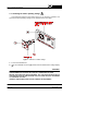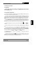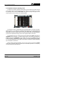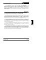
1
MC-377 INSTRUCTION MANUAL
LEVEL METER FOR ANALOGUE AND
DIGITAL TV
MC-377
1 GENERAL
1.1 Description
The MC-377 is a compact, light-weight, portable instrument which offers installers
all the basic functions needed to guarantee the good operation of analogue and digital
TV installations.
The instrument covers television bands, hyperband, cable television S channels as
well as the satellite intermediate frequency band in K/C, up to 2050 MHz.
The MC-377 has two main operation modes: Monitor mode and Spectrum Analyser
mode:
The Spectrum Analyser mode enables all the signals present in a band to be viewed
on the monitor. The bandwidth represented in the spectrum mode can be selected as
either the complete band or a bandwidth defined by the user (from approximately 1/3
of the band in use to almost zero).
In the Monitor mode the instrument demodulates the analogue TV signal, which
enables a terrestrial or satellite television channel to be identified and its reception
observed. The signal level in monitor mode is represented by an analogue bar at the
top of the image whose length varies in proportion to the power received. In addition it
enables the line synchronism pulse to be observed, overlaid on the top centre of the
screen.
The MC-377 enables you to easily take the following measurements: analogue
signal levels, digital channel power and Carrier to Noise ratio (C/N) in analogue and
digital channels.
The instrument can also supply the voltage needed to power external units: aerial
pre-amplifiers and LNBs with 13 or 18 V, together with a 22 kHz signal superimposed
onto the voltage for the commutation of polarisation, band or signal switches.
September 1999
Page 1
MC-377 INSTRUCTION MANUAL
1.2 Specifications
TUNING
VHF
UHF
SAT
Resolution
Frequency indication
Display
RF INPUTS
Impedance
Connector
Maximum signal
Maximum input voltage
DC to 100 Hz
5 MHz to 2050 MHz
MEASUREMENTS
Types of measurements
Terrestrial digital signals
measurement
Satellite digital signals
measurement
Sensibility
TV bands
Satellite band
Reading
Page 2
LOW VHF band (VLO) from 48.25 to 168.25 MHz
HIGH VHF band (VHI) from 175,25 to 447.25 MHz
UHF band, from 455.25 to 855.25 MHz
Satellite IF band from 950 to 2050 MHz
10 kHz in VHF and UHF
100 kHz in SAT
By digital frequency counter
LCD, 5 digits
TV and SAT
75 Ω
BNC
130 dBµV
50 V rms (powered by the mains supply)
30 V rms (not powered by the mains supply)
130 dBµV
Analogue signals level
Digital channels power
C/N ratio of analogue and digital signals
Calibrated for a channel bandwidth of 7.607 MHz
Calibrated for a Symbol Rate of 27.500 MBauds
From 20 dBµV to 130 dBµV analogue signals
From 35 dBµV to 125 dBµV digital signals
From 40 dBµV to 100 dBµV analogue signals
From 45 dBµV to 95 dBµV digital signals
Scale calibrated in dBµV (linear) for analogue
signals level measurement.
Scale calibrated in dBµV (linear) for digital
channels power measurement.
Scale calibrated in dB (linear) for C/N ratio
measurement of analogue and digital signals.
September 1999
MC-377 INSTRUCTION MANUAL
Scales range
IF bandwidth
RF attenuators
60 dB for TV analogue signals
45 dB for TV digital signals
40 dB for SAT analogue signals
30 dB for TV digital signals
60 dB for C/N measurement
250 kHz (TV) and 18 MHz (SAT)
TV bands: 50 dB in 10 and 20 dB steps
Satellite band: 20 dB
Total accuracy (25 ºC ± 5 ºC)
TV bands
± 4 dB
Satellite band
± 6 dB
When carrying out level and power measurements it is necessary to apply the correction
chart which is delivered with the instrument.
Level acoustic indication
SPURIOUS SIGNALS
LOW VHF (VLO)
Analogue signals
Digital signals
HIGH VHF (VHI)
Analogue signals
Digital signals
UHF
Analogue signals
Digital signals
SAT
Analogue signals
Digital signals
MONITOR
Monitor controls
Monitor mode
TV standard
MC-377/1 Version
MC-377/2 Version
MC-377/4 Version
Sensibility
September 1999
Tone whose frequency varies with the received
signal level.
< 20 dBµV (input 65 dBµV not attenuated)
< 35 dBµV (input 75 dBµV not attenuated)
< 20 dBµV (input 75 dBµV not attenuated)
< 35 dBµV (input 75 dBµV not attenuated)
< 20 dBµV (input 75 dBµV not attenuated)
< 35 dBµV (input 75 dBµV not attenuated)
< 40 dBµV (input 75 dBµV not attenuated)
< 45 dBµV (input 75 dBµV not attenuated)
B&W CRT 4,5"
Brightness and contrast
TV analogue signals demodulation
Multistandard B, G, H and /L according to CCIR
standars
Multistandard M, N/L according to CCIR standards
Multinorm D, K/L according to CCIR standards
Multinorm I/L according to CCIR standards
> 40 dBµV for correct synchronism in TV bands
Page 3
MC-377 INSTRUCTION MANUAL
Spectrum Analyser Mode
Bandwidth
MAX mode
SPAN mode
SOUND
Demodulation
TV
TER
SAT
Level indication
Output power
Volume control
Built-in speaker
EXT. UNITS POWER SUPPLY
22 kHz signal
Voltage
Frequency
POWER SUPPLY
Battery
Voltage
Autonomy
Recharging time
Protections
Mains supply
Voltage
Frequency
Consumption
Page 4
Spectrum of the entire selected band, with a
marker on the tuned frequency.
Frequency spectrum representation around the
tuned frequency, with variable bandwidth from 1/3
of the band (approximately) to almost zero.
Analogue channels
Mono
According to CCIR standard or manual tuning
between 4.5 and 6,5 MHz except in the L standard
and version MC-377/1.
Tuning between 5 and 8 MHz
Tone whose frequency varies according to signal
level
0.2 W
0/13/18V, 350 mA. Indicator of consumption higher
than 50 mA and protections against short circuits
and 50 VAC.
Selectable ON/OFF
0.6 V ± 0.2 V
22 kHz ± 4 kHz
12 V-2.6 Ah
>1 hour without external units powering (at 30%
on/off).
40 minutes approximately with external units
powering (at 30% on/off).
8 h approximately (starting from a total discharge)
Low battery indication (blinking colon on the
display).
Minimum charge automatic cut-off.
110-125-220-230/240 V AC with voltage selector
50-60 Hz
55 W
September 1999
MC-377 INSTRUCTION MANUAL
OPERATING ENVIRONMENTAL CONDITIONS
Altitude
Up to 2000 m
Temperature margin
From 5 ºC to 40 ºC
Max. relative humidity
80% (up to 31 ºC),
decreasing lineally up to 50% at 40 ºC.
MECHANICAL FEATURES
Dimensions
Weight
W. 280 x H. 95 x D. 250 mm (without carrying bag)
5.2 kg (battery included)
INCLUDED ACCESSORIES
Model
Description
AD-050
BNC/m-ANT/f adapter
AD-051
BNC/m -F/f adapter
DC-236
Carrying bag
CA-005
Power cord
CB-041
Rechargeable battery Pb 12 V / 2.6 Ah
Fuse 3.15 A - T - 250 V IEC 127
OPTIONAL ACCESSORIES
Model
Description
AMC/1
Reference antenna
AD-052
BNC/m-TV/f (NF) adapter
AT-20
20 dB attenuator
CV-550
5-50 MHz converter
LN-370B
Low noise amplifier
MC-75/300
75 Ω (BNC) / 300 Ω (TV) adapter
NG-282
Noise generator
OPTIONS
OPT-377/10
OPT-377/63
Level and power measuring scales in dBmV
Satellite band extension up to 2100 MHz
VERSIONS
MC-377/1
MC-377/2
MC-377/4
Multinorm M, N/L according to CCIR standards
Multinorm D, K/L according to CCIR standards
Multinorm I/L according to CCIR standards
September 1999
Page 5
MC-377 INSTRUCTION MANUAL
Page 6
September 1999
MC-377 INSTRUCTION MANUAL
2 SAFETY RULES
2.1 General
*
Use this equipment connected only to devices or systems with their negative of
measurement connected to ground potential.
*
This is a class I equipment, for safety reasons plug it to a supply line with the
corresponding ground terminal.
*
This equipment can be used in Overvoltage Category II installations and Pollution
Degree 2 environments.
*
When using some of the following accessories use only the specified ones to
ensure safety:
Rechargeable battery
Power cord
*
Observe all specified ratings both of supply and measurement.
*
Remember that voltages higher than 60 V DC or 30 V AC rms are dangerous.
*
Use this instrument under the specified environmental conditions.
*
The user is only authorized to carry out the following maintenance operations:
Replace the battery.
Replace the mains fuse of the specified type and value.
On the Maintenance paragraph the proper instructions are given.
Any other change on the equipment should be carried out by qualified
personnel.
*
The negative of measurement is at ground potential.
*
Do not obstruct the ventilation system
*
Follow the cleaning instructions described in the Maintenance paragraph
September 1999
Page 7
MC-377 INSTRUCTION MANUAL
*
Symbols related with safety:
DIRECT CURRENT
ALTERNATING CURRENT
DIRECT AND ALTERNATING
GROUND TERMINAL
PROTECTIVE CONDUCTOR
FRAME TERMINAL
EQUIPOTENTIALITY
ON (Supply)
OFF (Supply)
DOUBLE INSULATION
(Class II protection)
CAUTION
(Risk of electric shock)
CAUTION REFER TO MANUAL
FUSE
2.2 Specific precautions
When using the equipment powered by the mains supply it is suitable to be out of
its carrying case.
Page 8
September 1999
MC-377 INSTRUCTION MANUAL
3 INSTALLATION
The MC-377 level meter is designed for use as a portable device. A carrying case
is supplied to simplify transport and to allow the user to take measurements
conveniently during the installation of the antenna.
3.1 Operating on the electrical mains supply
Although the device was designed for use as portable equipment, it can also
operate when connected to the mains power supply. Connect the device to the mains
and press the start switch I/O [3]. The level meter is now in operation and the battery
will recharge slowly.
September 1999
Page 9
MC-377 INSTRUCTION MANUAL
3.1.1 Selecting the mains operating voltage
This equipment requires a mains power source of 110-125-220 or 230/240 V AC
50 to 60 Hz. Mains operating voltage can be selected at the mains base.
Figure 1.- Selection of mains voltage.
1.- Pull out the fuseholder lid.
2.- Insert the fuseholder lid so the [A] pointer faces the desired mains voltage display
[B].
CAUTION
THE EQUIPMENT IS FACTORY SET FOR 220 V OPERATING VOLTAGE.
BEFORE SWITCHING ON THIS INSTRUMENT, SET THE VOLTAGE SELECTOR TO
THE PROPER POSITION AND BE SURE THAT THE FUSE VALUE IS ACCORDING
TO THE MAINS VOLTAGE.
AVOIDING THESE DIRECTIONS COULD DAMAGE THE EQUIPMENT.
Page 10
September 1999
MC-377 INSTRUCTION MANUAL
3.2 Operating on the battery
The MC-377 is a portable device powered by a 12 volt internal battery. Before taking
any measurements, the battery charge must be checked. If the battery is low (a voltage
lower than 11.2 V) colon sign (:) will appear blinking on the display of the frequency
counter, under this circumstance the equipment must be connected to the mains to
carry out the battery charge.
For the device to operate on the battery, disconnect the power cord and press the
start switch I/O [3].
If the battery is very low, the cut-off circuit will prevent the device from functioning.
In such a situation the battery must be recharged immediately.
3.2.1 Recharging the battery
The MC-377 has an incorporated battery-charger which can be directly connected
to the mains. Battery charging can take place during the normal working day. The
instrument may still be used while the battery is being charged, under these conditions
the battery will charge to up to 90% of its capacity.
To recharge the battery, connect the device to the mains supply without pressing
the start switch I/O [3]. The length of time it takes to recharge depends on the condition
of the battery. If it is very low (the low battery message appears) recharging period is
7-8 hours. The indicator light LINE [16] should remain lit.
IMPORTANT
The battery charge must always exceed the minimum cut-off charge.
To ensure the best results, the lead battery in this device must always be fully charged.
If the equipment has been in storage or used only occasionally for a long period of time,
it is ABSOLUTELY NECESSARY to check the full-charge functions periodically (every
six months, for example), and to compensate for the self-discharging effect of the
battery. The rate at which a fully charged battery self-discharges depends on the
temperature. For example, at an ambient temperature of 20 ºC, the battery suffers a
50% loss after 16 months and at 40 ºC it loses the same charge in only 5 months (these
are reference data). If the battery remains very low for a period of 4 weeks or more, it
will not accept recharging since the plates are sulphated and must be replaced.
September 1999
Page 11
MC-377 INSTRUCTION MANUAL
Page 12
September 1999
MC-377 INSTRUCTION MANUAL
4 OPERATING INSTRUCTIONS
4.1 Description of the controls and elements
Front panel
Figure 2.- Front panel.
[1]
MONITOR
[2]
Noise Limit
Luminous indicator showing detected noise level below meter noise level when
measuring C/N.
[3]
I/O
[4]
STD L / BAND C
On / Off key.
Double function selector according on the active band.
In terrestrial bands.
Pressed key: it selects the "L" system.
Released key: it selects B/G, I and D/K systems.
In satellite band.
Pressed key: it selects the inverted video for the C BAND.
Released key: it selects the positive video for the K BAND.
September 1999
Page 13
MC-377 INSTRUCTION MANUAL
[5]
MON./SPEC
Operating mode selector:
Pressed key (MON.): Monitor Mode. The monitor [1] shows the demodulated TV
signal corresponding to the tuned frequency.
Released key (SPECT): Spectrum Analyser Mode. The monitor [1] shows a
frequency representation of the signal levels present in the band.
[6]
SPAN/MAX
(Operational only in Spectrum Analyser mode)
Selects bandwidth represented in the Spectrum Analyser mode:
Pressed key (SPAN mode): Variable bandwidth, modified by the SPAN control [23].
Released key (MAX mode): Maximum bandwidth (shows the complete band).
[7]
VLO
LOW VHF band selector.
[8]
VHI
HIGH VHF band selector.
[9]
UHF
UHF band selector.
[10]
SAT
Satellite intermediate frequency selector.
[11]
DIG
Digital channels measuring mode selector.
[12]
22 kHz
Activates the 22 kHz square signal superimposed onto the external unit supply
voltage.
[13]
VDC 0/13/18 V External units power supply selector.
[14]
10 dB
Selects 10 dB attenuation in the terrestrial bands.
[15]
20 dB
Selects 20 dB attenuation in the terrestrial bands.
[16]
20 dB
Selects 10 dB attenuation in the terrestrial and satellite bands.
When controls [14], [15] and [16] are selected simultaneously, the RF attenuation
is 50 dB in terrestrial bands.
[17]
LINE
Light indicator. Indicates whether the instrument is connected to the mains.
[18]
SHORT
Luminous indicator showing over-consumption by the external unit or short circuit.
Page 14
September 1999
MC-377 INSTRUCTION MANUAL
[19]
SAT
[20]
DRAIN
[21]
TV
RF signal input in terrestrial bands and external unit powering (antenna previous
amplifiers) (0/13/18 V ± 22 kHz).
[22]
Digital frequency counter display
Digital presentation of the tuned frequency in MHz. In the maximum bandwidth
spectrum analyser operating mode (MAX) the digital frequency presentation is
inhibited.
[23]
SPAN
(Operational only in the variable bandwidth Spectrum Analyser mode -SPAN-).
Defines the frequency bandwidth to be shown.
[24]
TUNING
[25]
TV / TUNING Tuning control of the audio carrier:
Terrestrial bands:
Pressed control:
Sound corresponds to the internal filter according to CCIR
standard.
Released control: Variable tuning between 4.5 and 6.5 MHz for the various
TV standards, except standard L and in version MC-377/1,
TV standard M/N.
Satellite band:
Variable tuning between 5 and 8 MHz irrespective of
whether pressed or released.
[26]
FINE TUNING Fine tuning control.
September 1999
Satellite IF RF input and external unit powering (LNB) 0/13/18 V + 22 kHz.
Luminous indicator showing the external unit normal consumption
Tuning control.
Page 15
MC-377 INSTRUCTION MANUAL
[27]
Audio control and activation of the measurement information over the
image:
Pressed control:
Selects television sound demodulation and permits the volume
to be altered, also:
In Monitor mode it activates the measurement bar and the
representation of the synchronism pulse.
In Spectrum Analyser mode, SPAN mode, it activates the C/N
measurement bar.
Released control: Selects the acoustic signal to represent the level, the tone of
which varies with the power received, and eliminates the
measurement information from the monitor.
[28]
CRT brightness control.
[29]
CRT contrast control.
[30]
DIGITAL
Digital channels measuring mode luminous indicator.
[31]
ANALOG
Analogue channels measuring mode luminous indicator.
[32]
CH POWER
Measuring scale in dBµV (or in dBmV for the OPT-377/10 option) for the measure
of digital channels power.
[33]
LEVEL
Measuring scale in dBµV (or in dBmV for the OPT-377/10 option) for the measure
of analogue signals level.
[34]
Measuring scale in dB for the measure of the C/N ratio.
Lateral
[35]
Power supply input for voltages of 110-125-220-230/240 V, 50-60 Hz with voltage
selector and fuse.
Page 16
September 1999
MC-377 INSTRUCTION MANUAL
4.2 Using the level meter
4.2.1 Start-up
Press the I/O control [3]. The frequency counter display [22] will show the tuned
frequency in MHz, except when the instrument is in MAX bandwidth spectrum analyser
mode (SPAN/MAX key [6]).
4.2.2 Preliminary adjustments
Connect the aerial signal to one of the inputs, TV [21] or SAT [19], depending on the
band you wish to analyse: VLO/VHI/UHF or SAT.
If necessary, power the external units (aerial pre-amplifiers or LNB) using switch VDC
[13] (0/13/18 V) and activate the 22 kHz commutation signal placing the 22 kHz switch [12]
in the ON position. When activating the external unit voltage supply, make sure that the
DRAIN luminous indicator [20] remains lit and that the SHORT indicator [18] stays off.
Using the MON./SPEC key [5], select the Monitor or Spectrum Analyser mode. You are
recommended to first select the complete band Spectrum Analyser mode (SPAN/MAX key
[6] released) to view all the signals present on the band at the same time.
Adjust the brightness and contrast of the CRT screen with the
controls.
[28] and
[29]
Select the desired frequency band with the VLO [7], VHI [8], UHF [9] and SAT [10]
keys.
Tune to the desired frequency using the TUNING [24] and FINE TUNING [26] controls,
the latter enables a more accurate tuning to be performed, especially in the UHF band. In
the event of the frequency counter display [22] not showing anything, press the SPAN/MAX
key [6] and adjust the represented bandwidth using the SPAN control [23].
If necessary, use the 10 dB [14], 20 dB [15] and 20 dB keys [16] to select the
appropriate attenuation.
Adjust the volume with the control
[27] or, if you wish, release the control in order
to select the acoustic level signal, this will help you to search for the maximum signal level
without having to continually watch the measurement screen.
September 1999
Page 17
MC-377 INSTRUCTION MANUAL
4.2.3 Spectrum Analyser operating mode
The Spectrum Analyser operating mode enables you to be easily and quickly informed
on the signals present in each band of the zone or region you are currently in. To select
this operating mode, extract the MON./SPEC key [5] and an image will appear on the
monitor similar to the one shown in the following figure.
Figure 3.- Spectrum analyser mode, MAX mode.
The monitor will show a representation of the signals present in the band in function
of each frequency. The vertical axis corresponds to the frequency, the higher frequencies
being higher up on the screen and the lower ones further down. The horizontal axis
represents the level of the signals present in the band, the amplitude of the lobes appearing
on the screen represent the energy of the various signals present in the band.
The bandwidth shown can correspond to the entire selected band (MAX mode) with the
SPAN/MAX key [6] released, or a smaller margin close to the current tuning frequency
(SPAN mode) with the SPAN/MAX key [6] pressed, then acting on the SPAN control [23]
in order to select the bandwidth to be shown, this may be chosen between approximately
1/3 of the band (depending on the width of each band, to maintain the power calibration)
and a bandwidth of almost zero.
Having chosen a specific bandwidth, you may now vary the tuning with the TUNING
control [24] to gradually sweep the entire band of selected frequencies. The frequency
counter will show the tuned frequency.
Page 18
September 1999
MC-377 INSTRUCTION MANUAL
In the complete band Spectrum Analyser mode (MAX, with the SPAN/MAX key [6]
released) a white horizontal line will appear on the monitor (tuning mark) showing the
tuning frequency (as can be seen in the previous figure). As you move across the
frequencies with the TUNING control [24] you will see the mark move across the entire
spectrum, allowing you to approximately pre-tune the frequency corresponding to the lobe
that the mark is on.
IMPORTANT
IN THE MAX REPRESENTATION MODE, THE TUNING FREQUENCY READING
ON THE FREQUENCY COUNTER DISPLAY [22] IS DEACTIVATED.
When obtaining the levels of different signals, you will find a set of continuous vertical
lines on the image, together with others in the form of points, forming a grid which
corresponds to divisions of 10 and 5 dB respectively, depending on the scales [32] or [33]
found along the top of the monitor [1]. See section (4.2.5 Taking measurements).
In order to avoid saturation of the input stage, if you have several channels present at
the input with amplitudes of about 75-80 dBµV for analogue signals, or 70-75 dBµV in the
case of digital signals, you should use RF attenuators and thereby avoid the possibility of
producing measurement errors.
One of the applications of the MC-377 as a spectrum analyser is in searching for the
best orientation and placement of receiver aerials, both for terrestrial TV and most
particularly in the case of satellite TV.
In the satellite band (SAT), the device is also a great aid in the placement and correct
orientation of aerials because it can detect a satellite signal even when the received signal
is much weaker than the minimum level required to obtain an image. Furthermore, the
instrument permits the exact adjustment of the LNB regarding its physical position to obtain
the maximum ratio between Horizontal and Vertical polarities.
September 1999
Page 19
MC-377 INSTRUCTION MANUAL
4.2.4 Monitor operating mode
In the Monitor operating mode the MC-377 works like a conventional television. In
addition, when the audio control
[27] is pressed, you will see a horizontal bar at the
top of the image whose length corresponds to the level/power of the tuned signal. Below
this bar, superimposed on the middle top of the TV image, the line synchronism pulse is
shown with which it is possible to easily detect any possible saturation of the amplifiers in
terrestrial bands. The following figure shows the three types of information appearing
on-screen in the Monitor operating mode: demodulated television image (the example
shown in figure 4 shows a scale of greys), measurement bar (67 dBµV in figure 4) and a
representation of the line synchronism.
Figure 4.- Monitor operation mode.
To better observe and identify the tuned channel, it is possible to eliminate the
measurement bar and the synchronism pulse by releasing the audio control
[27].
4.2.5 Taking measurements
The MC-377 enables three different kinds of measurements to be taken:
Analogue signals level measurement
Digital channels power measurement
C/N ratio measurement of analogue and digital signals.
The following sections describe how to take each one of these measurements.
Page 20
September 1999
MC-377 INSTRUCTION MANUAL
4.2.5.1 Measuring the level of analogue signals
To measure the level of an analogue signal, proceed as described below:
-
Select the Spectrum Analyser operating mode, SPAN mode, and with the help of
the frequency counter display [22] tune the signal using the TUNING [24] and FINE
TUNING controls [26]. Adjust the SPAN control [23] to select a bandwidth so that
the signal occupies the most part of the image. If you are dealing with a television
signal it is also possible to take the measurement from the Monitor mode (in this
case press the audio control [27] so that the measurement bar appears at the top
of the image).
-
Select the measurement scale for analogue signals LEVEL [33], in order to do this
the DIG key [11] should be released and the ANALOG indicator [31] should remain
lit.
-
Read the level on the screen with the help of the scale calibrated in dBµV
(20-80 dBµV) LEVEL [33]. If the level is very close to 80 dBµV or is greater than
this value, the signal should be attenuated using the RF attenuators.
On terrestrial bands the [14] 10 dB, [15] 20 dB and [16] 20 dB attenuation keys
must be pressed in order to obtain the signal level into the scale. The total
attenuation is the addition of the keys pressed.
On the satellite band the [16] 20 dB attenuation key must be pressed.
-
The actual signal level is calculated in the following manner:
Level [dBµV] = Reading [dBµV] + Attenuation [dB] + Correction Factor [dB]
VERY IMPORTANT
THE CORRECTION FACTOR IS OBTAINED FROM THE CORRECTION CHART WHICH
IS DELIVERED WITH THE INSTRUMENT. THIS VALUE DEPENDS ON THE
FREQUENCY.
September 1999
Page 21
MC-377 INSTRUCTION MANUAL
EXAMPLE A. Measuring the level of an analogue signal
Take the following figure as an example, showing a television channel: the lower part
of the spectrum shows the lobe corresponding to the video carrier (69 dBµV) and in the
upper part you can see the audio carrier (63 dBµV) preceded by the chrominance signal
(40 dBµV). Note that the measurements are taken on the LEVEL scale [33].
Measurement conditions:
Video carrier freq.: 551.25 MHz
RF attenuation:
10 dB
Mode:
ANALOG
Figure 5.- Example of analogue signal level measurement.
We assume that the instrument was delivered with the following Correction Chart:
Figure 6.- Example of correction chart.
From the correction chart you find that the Correction Factor to be applied to the
frequency you are working with (551.25 MHz) is -1 dB. Therefore, the actual signal level
is:
Level [dBµV] = Readout (69 dBµV) + Atten. (10 dB) + Correct. factor (-1 dB) = 78 dBµV
Page 22
September 1999
MC-377 INSTRUCTION MANUAL
4.2.5.2 Measuring the power of digital channels
The main characteristic of digital signals is that they distribute their energy across the
entire channel bandwidth (in the same way as a noise signal), in other words they do not
posses a differentiated carrier. Given this different nature from analogue signals the method
used for measuring can not be the same. You must use a detector appropriate for signals
of a 'noisy nature' and take into consideration that the bandwidth of the measuring filter is
smaller than the bandwidth of the channel.
The MC-377 takes into account the properties of digital signals and enables the power
of digital signals to be measured almost automatically, just follow the procedure below:
-
Select the Spectrum Analyser operating mode, SPAN mode, and with the help of the
frequency counter display [22] tune the signal using the TUNING [24] and FINE
TUNING controls [26]. Adjust the SPAN control [23] to select a bandwidth so that the
signal occupies the most part of the image.
-
Select the digital signal measurement scale CH POWER [32], the DIG key [11] should
be in the pressed position and the DIGITAL indicator [30] should remain lit.
-
Read the level on the screen with the help of the scale calibrated in dBµV
(25-75 dBµV) CH POWER [32]. If the level is very close to 75 dBµV or is greater than
this value, the signal should be attenuated using the RF attenuators.
-
The actual signal level is calculated in the following manner:
Power [dBµV] = Reading [dBµV] + Atten. [dB] + Correction Factor [dB]
VERY IMPORTANT
THE CORRECTION FACTOR IS OBTAINED FROM THE CORRECTION CHART WHICH
IS DELIVERED WITH THE INSTRUMENT. THIS VALUE DEPENDS ON THE
FREQUENCY.
September 1999
Page 23
MC-377 INSTRUCTION MANUAL
EXAMPLE B.- Measuring the power of a digital signal
Take the following figure as an example, showing a digital signal:
Measurement conditions:
Central frequency: 650.00 MHz
RF attenuation:
0 dB
Mode:
DIGITAL
Figure 7.- Example of digital channel power measurement.
Using the CH POWER scale [32] (blue background) you can read a power of 45 dBµV.
From the correction chart in figure 6, you obtain the Correction Factor to be applied to
the frequency you are working with (650.00 MHz) which is 0 dB. Therefore, the actual
power of the channel is:
Power [dBµV] = Reading (45 dBµV) + Atten. (0 dB) + Correct. Factor (0 dB) = 45 dBµV
To obtain further information on the digital signal measurement method refer to
Appendix A Digital TV signals.
Page 24
September 1999
MC-377 INSTRUCTION MANUAL
4.2.5.3 Measuring the C/N ratio of analogue and digital signals
Measuring the Carrier/Noise ratio provides us with information on the quality of
analogue signals and the sturdiness of digital signals. The Spectrum Analyser operating
mode, SPAN mode, enables this measurement to be made almost automatically.
To measure C/N, the MC-377 measures the maximum level or power (depending on
whether the analogue or digital measurement mode has been selected) present inside the
represented bandwidth (defined by the SPAN control [23]) and subtracts the minimum noise
level measured inside this bandwidth. Therefore, for the measurement to be correct it is
essential that the maximum and minimum level signals appearing on the monitor are those
for which you wish to evaluate the C/N ratio.
4.2.5.3.1 Measuring the C/N ratio of analogue channels
-
Select the Spectrum Analyser operating mode, SPAN mode, and release the audio
control
[27] so that the C/N measurement bar does not get in the way when
choosing the right SPAN.
-
Select the analogue signal measurement scale, LEVEL [33], the DIG key [11] should
be released and the ANALOG indicator [31] should remain lit.
-
Tune the signal using the TUNING [24] and FINE TUNING controls [26] with the help
of the frequency counter display [22]. Turn the SPAN control [23] to select a bandwidth
so that the maximum signal on the monitor is the video carrier and the minimum level
signal is the noise. Remember that the noise can be measured, as you wish, either
inside or outside the channel.
-
Press the audio control
-
Read the measurement on the monitor with the help of the scale calibrated in dB
(10-60 dB) C/N [34]. If the signal level is close to 80 dBµV or is greater than this value
the signal should be attenuated using the RF attenuators.
[27] to show the C/N measurement bar.
If on taking the measurement the Noise Limit indicator [2] should light up, this means
that the actual noise level is less than the noise level of the MC-377 itself and, therefore,
the instrument can not measure under these conditions. In this event it can be confirmed
that the actual measurement is better than the one obtained (given that the actual noise
is less). One way to avoid this situation is to amplify the signal, though then you will have
to take into consideration the noise introduced by the amplifier.
September 1999
Page 25
MC-377 INSTRUCTION MANUAL
EXAMPLE C.- Measuring the C/N ratio of an analogue signal
Take the following figure as an example, showing an analogue television signal:
Measurement conditions:
Video carrier freq.: 520.25 MHz
RF attenuation:
10 dB
Mode:
ANALOG
Noise Limit indicator ON
Figure 8.- Measuring the C/N ratio of an analogue channel.
In the example in the previous figure it has been decided to measure the C/N ratio
inside the channel, in other words the noise is measured inside the channel at the point
where the content of the video signal is the minimum.
From the C/N scale [34] you obtain a C/N ratio of 41 dB.
Given that the Noise Limit indicator [2] was lit when the measurement was taken, we
may come to the conclusion that the C/N ratio is greater than 41 dB.
Page 26
September 1999
MC-377 INSTRUCTION MANUAL
4.2.5.3.2 Measuring the C/N ratio of digital channels
The C/N ratio of digital channels is measured in a similar way to analogue signals, but
remember that for the instrument to interpret the signal as being digital you should select
the digital signal measurement mode: simply, the DIG key [11] should be in the pressed
position and the DIGITAL indicator [30] should remain lit.
EXAMPLE D.- Measuring the C/N ratio of a digital channel
Audio control
[27] released.
Audio control
[27] pressed.
Measurement conditions:
Frequency :
RF attenuation:
Noise limit indicator
650.00 MHz
0 dB
ON
Figure 9.- Measuring the C/N ratio of a digital channel.
The previous figure shows the image appearing on the monitor when the audio control
[27] is released (left) and when it is pressed (right, showing the C/N measurement bar).
You are advised to adjust the SPAN control [23] so that there is no C/N measurement bar,
as this may mask a signal from a lower adjacent channel and spoil the measurement.
From the C/N scale [34] (grey background) you obtain a C/N ratio of 21 dB.
Given that the Noise Limit indicator [2] was lit when the measurement was taken, we
may come to the conclusion that the C/N ratio is greater than 21 dB.
September 1999
Page 27
MC-377 INSTRUCTION MANUAL
Page 28
September 1999
MC-377 INSTRUCTION MANUAL
5 MAINTENANCE
5.1 Operating recommendations
One of the more common causes of breakdowns in TV signal level meters is the
generation of internal short-circuits due to the introduction of small conductors. These
conductors tend to be coaxial cable shielding wire, you are therefore advised TO NOT CUT
COAXIAL CABLES OVER THE INSTRUMENT.
5.2 Fuses replacement
5.2.1 Mains fuse replacement
The fuseholder lid is placed in the mains base and it is the voltage selector. See
figure 1 Selection of mains voltage, paragraph 3.1.1 Selecting the mains operating voltage.
To substitute the fuse, disconnect the power cord.
With an appropriate screw driver remove the fuseholder lid.
Substitute the melt fuse for another with following characteristics:
IMPORTANT
FUSE TYPE SHOULD BE 5 x 20 mm AND:
2A
3.15 A
T
T
250 V
250 V
FOR 220, 230/240 V
FOR 110 AND 125 V
AVOIDING THESE DIRECTIONS COULD DAMAGE THE EQUIPMENT
When inserting the fuseholder lid be careful that the voltage selector is in the correct
position according to the mains.
5.2.2 Internal fuses which user cannot replace
The following fuse is found on the base board. Its location identification and
characteristics are the following:
F1,
September 1999
5A
F
63 V
SMD
Page 29
MC-377 INSTRUCTION MANUAL
5.3 Battery replacement
The battery should be replaced when you notice that its capacity, once it has been
charged, has decreased considerably (its mean life is of some 4 years). To change the
battery follow next procedure.
With the instrument off and disconnected from the mains:
-
Remove the securing screws from the upper and lower covers (6 screws on each
cover). Remove the 2 covers.
-
Disconnect the battery connection terminals.
-
Place the instrument face down so you can see the underside of the base board.
Remove the screw securing the battery holder to the base board, this screw is
found located on the base board next to the rear panel of the instrument.
-
Remove the screws securing the battery holder to the rear panel of the instrument
(4 screws and their respective washers and grover washers). The battery holder
will now be freed.
-
Take out the battery together with the holder antiacid protector. Place the antiacid
protector on the new battery and insert it into the holder. Take the utmost care to
not invert the polarity when putting in place.
-
Secure the battery holder to the rear panel (4 screws and their respective washers
and grover washers).
-
Secure the battery to the base board using the screw and serrated washer.
-
Reconnect the battery: red cable to the positive terminal (+), black cable to the
negative terminal (-).
-
Finally, secure the upper and lower covers with the respective screws and
washers.
VERY IMPORTANT
AVOID ANY TYPE OF SHORT CIRCUIT AMONG THE CABLES CONNECTED TO THE
BATTERY, SINCE THE RESULTING HIGH CURRENT MAY CAUSE SERIOUS DAMAGE
TO THE EQUIPMENT.
Page 30
September 1999
MC-377 INSTRUCTION MANUAL
5.4 Cleaning recommendations
CAUTION
TO CLEAN THE COVER, TAKE CARE THE INSTRUMENT IS DISCONNECTED.
CAUTION
DO NOT USE SCENTED HYDROCARBONS OR CHLORIZED SOLVENTS. SUCH
PRODUCTS MAY ATTACK THE PLASTICS USED IN THE CONSTRUCTION OF THE
COVER.
The cover should be cleaned by means of a light solution of detergent and water
applied with a soft cloth.
Dry thoroughly before using the system again.
September 1999
Page 31
MC-377 INSTRUCTION MANUAL
Page 32
September 1999
MC-377 INSTRUCTION MANUAL
APPENDIX A. DIGITAL TV SIGNALS
Terrestrial Digital Television (abbreviated as TDT) uses COFDM modulation (Coded
Orthogonal Frequency Division Multiplex) which possesses the main feature of immunity
to multi-path reflections.
Whereas the greater part of the power of an analogue channel is centred around the video
carrier, digital signals distribute their energy across the entire channel bandwidth. This
difference has important consequences when measuring the power of the channel.
TDT channels usually transmit 5 different TV programmes with their corresponding audio
signals and other data, in this same bandwidth an analogue modulation can only transmit
a single TV programme and its corresponding audio signal. Furthermore, due to the greater
efficiency of digital modulation, some 20 dB less power is needed for the same cover as
an analogue signal: therefore, a digital signal with a power of 40 dBµV at the receiver input
is equivalent to a level of 60 dBµV for analogue signals. On the other hand TDT receivers
require a minimum C/N value of between 19 and 26 dB in order to correctly decode a
signal, as opposed to the 43 dB necessary for analogue signals.
In the case of individual TDT installations without signal amplifiers, it is usually enough to
test the power of the signal at the input. On the other hand, in collective TDT installations
with signal amplifiers (which increase the noise level by adding the noise they generate)
it is also necessary to measure the C/N ratio to guarantee signal quality.
Satellite band uses QPSK modulation (Quaternary Phase Shift Keying) which as with all
digital TV signals uniformly spreads its energy across the entire band.
Digital channels in the satellite band are classified according to their bandwidth into broad
or narrow band channels. Channel bandwidth is uniquely related to Symbol Rate. This
parameter can take many values. Symbol Rate values of the order of 27.500 MBauds are
common for broad channels and of the order of 5.000 MBauds for narrow channels.
Naturally enough, the information transmitted across narrow channels is more limited.
In satellite band, relying solely on measuring power can be deceptive, as signal quality
depends in great measure on the noise introduced by the LNB. It is therefore necessary
to measure the C/N ratio. For the purposes of orientation and digital channels a C/N ratio
of approximately 8 dB may be sufficient for a Symbol Rate of 27.500 MBauds, or
approximately 2.3 dB for a Symbol Rate of 5.000 MBauds.
September 1999
Page 33
MC-377 INSTRUCTION MANUAL
MEASURING THE POWER OF DIGITAL CHANNELS
As we have already mentioned, digital signals distribute their energy uniformly across the
entire bandwidth of the channel, therefore measuring the power of digital channels depends
on the channel Bandwidth or the Symbol Rate (the other modulation parameters do not
affect this measurement).
The MC-377 gives power measurements for digital channels under the precision specified
for terrestrial signals of a bandwidth of 7.607 MHz and for satellite signals of a bandwidth
corresponding to a Symbol Rate of 27.500 MBauds. Measurements on channels made with
characteristics different from these should be manually corrected as described below.
TDT power for bandwidths other than 7.6 MHz
Terrestrial digital channels can have bandwidths of 7.607 / 6.65 / or 5.70 MHz depending
on the channelling in each country (these bandwidths correspond to a channel separation
of 8, 7 and 6 MHz respectively).
Power measurements made on terrestrial digital channels with a Bandwidth other than
7.607 MHz should be corrected according to the following table.
BANDWIDTH [MHz]
6.656250
5.705357
CORRECTION [dB]
-1
-2
Therefore, for example, the power measurement of a digital channel of 6.65 MHz should
have 1 dB subtracted from the reading obtained by the MC-377.
SDT power for Symbol Rate other than 27.500 MBauds
Power measurements made on satellite digital channels with a Symbol Rate other than
27.500 MBauds should be corrected according to the following table.
SYMBOL RATE [MBauds] CORRECTION [dB]
30.000
+0.5
22.000
-1.1
20.000
-1.3
17.180
-2.0
9.096
-2.6
5.632
-3.0
5.000
-3.1
Therefore, for example, the power measurement of a digital channel of 22.000 MBauds
should have 1.1 dB subtracted from the reading obtained by the MC-377.
Page 34
September 1999
MC-377 INSTRUCTION MANUAL
TABLE OF CONTENTS
1 GENERAL . . . . . . . . . . . . . . . . . . . . . . . . . . . . . . . . . . . . . . . . . . . . . . . . . . . . . .
1.1 Description . . . . . . . . . . . . . . . . . . . . . . . . . . . . . . . . . . . . . . . . . . . . . . . . .
1.2 Specifications . . . . . . . . . . . . . . . . . . . . . . . . . . . . . . . . . . . . . . . . . . . . . . .
1
1
2
2 SAFETY RULES . . . . . . . . . . . . . . . . . . . . . . . . . . . . . . . . . . . . . . . . . . . . . . . . .
2.1 General . . . . . . . . . . . . . . . . . . . . . . . . . . . . . . . . . . . . . . . . . . . . . . . . . . .
2.2 Specific precautions . . . . . . . . . . . . . . . . . . . . . . . . . . . . . . . . . . . . . . . . . .
7
7
8
3 INSTALLATION . . . . . . . . . . . . . . . . . . . . . . . . .
3.1 Operating on the electrical mains supply . .
3.1.1 Selecting the mains operating voltage
3.2 Operating on the battery . . . . . . . . . . . . . .
3.2.1 Recharging the battery . . . . . . . . . . .
.
.
.
.
.
.
.
.
.
.
.
.
.
.
.
.
.
.
.
.
.
.
.
.
.
.
.
.
.
.
.
.
.
.
.
.
.
.
.
.
.
.
.
.
.
.. 9
.. 9
. 10
. 11
. 11
4 OPERATING INSTRUCTIONS . . . . . . . . . . . . . . . . . . . . . . . . . . . . . . . .
4.1 Description of the controls and elements . . . . . . . . . . . . . . . . . . . .
4.2 Using the level meter . . . . . . . . . . . . . . . . . . . . . . . . . . . . . . . . . .
4.2.1 Start-up . . . . . . . . . . . . . . . . . . . . . . . . . . . . . . . . . . . . . . . .
4.2.2 Preliminary adjustments . . . . . . . . . . . . . . . . . . . . . . . . . . . .
4.2.3 Spectrum Analyser operating mode . . . . . . . . . . . . . . . . . . . .
4.2.4 Monitor operating mode . . . . . . . . . . . . . . . . . . . . . . . . . . . .
4.2.5 Taking measurements . . . . . . . . . . . . . . . . . . . . . . . . . . . . .
4.2.5.1 Measuring the level of analogue signals . . . . . . . . . . . .
4.2.5.2 Measuring the power of digital channels . . . . . . . . . . . .
4.2.5.3 Measuring the C/N ratio of analogue and digital signals
4.2.5.3.1 Measuring the C/N ratio of analogue channels . . .
4.2.5.3.2 Measuring the C/N ratio of digital channels . . . . .
.
.
.
.
.
.
.
.
.
.
.
.
.
.
.
.
.
.
.
.
.
.
.
.
.
.
.
.
.
.
.
.
.
.
.
.
.
.
.
.
.
.
.
.
.
.
.
.
.
.
.
.
.
.
.
.
.
.
.
.
.
.
.
.
.
.
.
.
.
.
.
.
.
.
.
.
.
.
13
13
17
17
17
18
20
20
21
23
25
25
27
5 MAINTENANCE . . . . . . . . . . . . . . . . . . . . . . . . . .
5.1 Operating recommendations . . . . . . . . . . . . .
5.2 Fuses replacement . . . . . . . . . . . . . . . . . . . .
5.2.1 Mains fuse replacement . . . . . . . . . . . .
5.2.2 Internal fuses which user cannot replace
5.3 Battery replacement . . . . . . . . . . . . . . . . . . .
5.4 Cleaning recommendations . . . . . . . . . . . . . .
.
.
.
.
.
.
.
.
.
.
.
.
.
.
.
.
.
.
.
.
.
.
.
.
.
.
.
.
.
.
.
.
.
.
.
.
.
.
.
.
.
.
29
29
29
29
29
30
31
APPENDIX A. DIGITAL TV SIGNALS . . . . . . . . . . . . . . . . . . . . . . . . . . . . . . . . . .
33
.
.
.
.
.
.
.
.
.
.
.
.
.
.
.
.
.
.
.
.
.
.
.
.
.
.
.
.
.
.
.
.
.
.
.
.
.
.
.
.
.
.
.
.
.
.
.
.
.
.
.
.
.
.
.
.
.
.
.
.
.
.
.
.
.
.
.
.
.
.
.
.
.
.
.
.
.
.
.
.
.
.
.
.
.
.
.
.
.
.
.
.
.
.
.
.
.
.
.
.
.
.
.
.
.
.
.
.
.
.
.
.
.
.
.
.
.
.
.
.
.
.
.
.
.
.
.
.
.
.
.
.
.
.
.
.
.
.
.
.
.
.
.
.
.
.
.
.
.
.
.
.
.
.
.
.
.
.
.
.
.
.
.
.
.
.
.
.
.
.
.
.
.
.
.
.
.
.
.
.
.
.