1
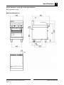
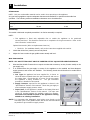
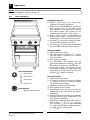
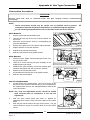
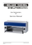
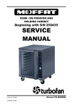
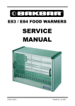
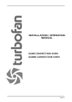
Gas Griddle To aster
G55T
Service Manual
Blue Seal Evolution Series G55T Griddle Toaster
Revision 1/
© Moffat Ltd, January 2007
WARNING:
ALL INSTALLATION AND SERVICE REPAIR WORK MUST BE CARRIED OUT BY
QUALIFIED PERSONS ONLY.
IMPORTANT: MAKING ALTERATIONS MAY VOID WARRANTIES AND APPROVALS.
Blue Seal Evolution Series G55T Griddle Toaster
Revision 1/
© Moffat Ltd, January 2007
Contents
This manual is designed to take a more in depth look at the G55T gas griddle toaster for the purpose of
making the units more understandable to service people.
There are settings explained in this manual that should never require to be adjusted, but for completeness
and those special cases where these settings are required to change, this manual gives a full explanation
as to how, and what effects will result.
Section
Page Number
1.
Specifications ............................................................................................ 1
2.
Installation ................................................................................................ 3
3.
Operation ................................................................................................... 6
4.
Cleaning / Maintenance ............................................................................ 8
5.
Trouble-shooting Guide ........................................................................... 11
5.1
5.2
6.
Trouble-shooting Chart
Fault Diagnosis
Service Procedures .................................................................................. 14
6.1
6.2
6.3
Access
Replacement
Adjustment / Calibration
7.
Accessories .............................................................................................. 18
8.
Exploded Parts Diagrams ........................................................................ 19
9.
Service Contacts ...................................................................................... 23
Appendix A: Gas Type Conversion ................................................................. 25
Blue Seal Evolution Series G55T Griddle Toaster
Revision 1/
© Moffat Ltd, January 2007
Blue Seal Evolution Series G55T Griddle Toaster
Revision 1/
© Moffat Ltd, January 2007
Specifications
1
Model Numbers Covered in this Specification
G55T Gas Griddle Toaster
External Dimensions
1
Blue Seal Evolution Series G55T Griddle Toaster
Revision 1/
© Moffat Ltd, January 2007
1
Specifications
Gas Supply (Non-UK Models)
Natural Gas
42 MJ/hr
42 MJ/hr
(39,800 Btu/hr)
(39,800 Btu/hr)
1.13 - 3.40 kPa
2.75 - 3.40 kPa
1.0 kPa (*)
2.5 kPa (*)
Input Rating (N.H.G.C.)
Supply Pressure
LP Gas (Propane)
(4.5” - 13.5” w.c.)
Operating Pressure
(11” - 13.5” w.c.)
(4.0” w.c.)
(10.0” w.c.)
1
Gas Connection
/2” BSP Male
Gas Supply (UK Models)
Heat Input (nett)
Gas Rate (nett)
Natural Gas (G20)
Propane (G31)
Nominal
11.0 kW
11.0 kW
Reduced
Nominal
Reduced
6.0 kW
1.16 m3/hr
0.63 m3/hr
5.6 kW
0.85 kg/hr
0.44 kg/hr
20 mbar
37 mbar
Supply Pressure
Burner Operating Pressure
10 mbar (*)
26 mbar (*)
1
Gas Connection
/2” BSP Male
Injector Sizes
Natural Gas (G20)
Propane (G31)
Main Burners
2.10mm
1.30mm
Pilot Burners
0.35mm
0.23mm
Toaster Internal Dimensions
Width
475 mm
Depth
570 mm
Height
190 mm
Toaster Racks
Toaster Rack Size
472 mm x 430 mm
Number of racks supplied
1
Weight
G55T (Net weight)
120 kg
2
Blue Seal Evolution Series G55T Griddle Toaster
Revision 1/
© Moffat Ltd, January 2007
Installation
2
Installation Requirements
NOTE:
• It is
use.
• This
able
most important that this appliance is installed correctly and that operation is correct before
Installation shall comply with local electrical, gas, health and safety requirements.
appliance shall be installed with sufficient ventilation to prevent the occurrence of unacceptconcentrations of health harmful substances in the room, the appliance is installed in.
Blue Seal Griddle Toasters are designed to provide years of satisfactory service and correct installation is
essential to achieve the best performance, efficiency and trouble-free operation.
This appliance must be installed in accordance with National installation codes and in addition, in
accordance with relevant National / Local codes covering gas and fire safety.
AUSTRALIA:
- AS5601
- Gas Installations.
NEW ZEALAND:
- NZS5261
- Gas Installation.
UNITED KINGDOM:
- Gas Safety (Installation & Use) Regulations 1998.
- BS6173
- Installation of Catering Appliances.
- BS5440
- 1 & 2 Installation Flueing & Ventilation.
IRELAND:
- IS 820
- Non - Domestic Gas Installations.
Installations must be carried out by qualified service persons only. Failure to install equipment to relevant
codes and manufacturers specifications shown in this section will void the warranty.
Components having adjustments protected (e.g. paint sealed) by the manufacturer, are only allowed to be
adjusted by a qualified service person. They are not to be adjusted by the installation person.
Unpacking
1. Remove all packaging and transit protection from the appliance including all protective plastic
coating from the exterior stainless steel panels.
2. Check equipment and parts for damage. Report any damage immediately to the carrier and
distributor.
3. Report any deficiencies to the distributor who supplied the appliance.
4. Check that the available gas supply is correct to that shown on the rating plate located on the right
hand inner side panel.
5. Check that the following parts have been supplied with the appliance:
Enamelled Crumb Tray
1
Toasting Rack
1
Toasting Rack Tray (St/Steel)
1
Grease Drawer
1
Adjustable Legs
4
Gas Regulator
1
Alternate Gas Conversion Kit
1
Location
1.
Installation must allow for a sufficient flow of fresh air for the combustion air supply.
Combustion Air Requirements:
Natural Gas (G20) 10m³/hr.
LPG (G31)
9m³/hr.
2.
Installation must include adequate ventilation means, to prevent dangerous build up of combustion
products.
3.
Position the appliance in its approximate working position.
4.
All air for burner combustion is supplied from underneath the appliance. The legs must always be
fitted and no obstructions placed on the underside or around the base of the appliance, as
obstructions will cause incorrect operation and/or failure of the appliance.
5.
Components having adjustments protected (e.g. paint sealed) by manufacturer are only allowed to
be adjusted by an authorised service agent. They are not to be adjusted by the installation person.
NOTE: Do not obstruct or block the appliances flue. Never directly connect a ventilation system to the
appliance flue outlet
3
Blue Seal Evolution Series G55T Griddle Toaster
Revision 1/
© Moffat Ltd, January 2007
2
Installation
Clearances
NOTE: Only non-combustible materials can be used in close proximity to this appliance.
Any gas burning appliance requires adequate clearance and ventilation for optimum and trouble-free
operation. The following minimum installation clearances are to be adhered to:
Combustible Surface
Non Combustible Surface
Left/Right hand side
50 mm
0 mm
Rear
50 mm
0 mm
Assembly
This model is delivered completely assembled. No further assembly is required.
NOTE:
• This appliance is fitted with adjustable feet to enable the appliance to be positioned
securely and level. This should be carried out on completion of the gas connection. Refer to the
'Gas Connection' section below.
Optional Accessories (Refer to Replacement Parts List)
1.
• Plinth Kit. For installation details, refer to the instructions supplied with each kit.
Check that all the feet (castors) are securely fitted.
2.
Adjust the feet to make the gas griddle toaster steady and level.
Gas Connection
NOTE: ALL GAS FITTING MUST ONLY BE CARRIED OUT BY A QUALIFIED SERVICE PERSON.
1.
Blue Seal Gas Griddle Toasters do not require an electrical connection, as they function totally on the
gas supply only.
2.
It is essential that the gas supply is correct for the appliance to be installed and that adequate
supply pressure and volume are available. The following checks should therefore be made before
installation:
a. Gas Type the appliance has been supplied for, is shown on
coloured stickers located above the gas connection and next to
the rating plate. Check that this is correct for the gas supply
the appliance is being installed for.
The gas conversion
procedure is detailed in this manual.
b. Supply Pressure required for this appliance is shown in the
“Specifications” Section of this manual. Check the gas supply to
ensure adequate supply pressure exists.
c. Input Rate of this appliance is stated on the Rating Plate and
in the “Specifications” section of this manual. The input rate
should be checked against the available supply line capacity.
Particular note should be taken if the appliance is being
added to an existing installation.
Rating Plate
NOTE: It is important that adequately sized piping runs directly to the
connection joint on the griddle toaster with as few tees and elbows
as possible to give maximum supply volume.
4
Blue Seal Evolution Series G55T Griddle Toaster
Revision 1/
© Moffat Ltd, January 2007
Installation
3.
2
Fit the gas regulator supplied, into the gas supply line as close to the appliance as possible.
NOTE: The gas pressure regulator provided with this appliance is convertible between Natural
Gas and LPG and is already converted ex-factory to the gas type labelled beside the
gas connection point. The regulator outlet pressure is fixed ex-factory and it is NOT to
be adjusted.
The regulator connections are 1/2" BSP female.
The connection to the appliance is 1/2" BSP male.
(Refer to the “Specifications” section for the gas supply location dimensions).
NOTE: A Manual Isolation Valve must be fitted to the individual appliance supply line.
4.
Correctly locate the griddle toaster into its final
operating position and using a spirit level, adjust
the legs so that the appliance is level and at the
correct height.
5.
Connect the gas supply to the appliance.
A
suitable jointing compound which resists the
breakdown action of LPG must be used on every
gas line connection, unless compression fittings are
used.
6.
Check all gas connections for leakages using soapy
water or other gas detecting equipment.
7.
Check that the gas operating pressure is as shown in the “Specifications” section.
Pressure Test Point
Low Fire Adjustment
WARNING:
DO
NOT USE A NAKED FLAME TO CHECK FOR GAS LEAKAGES .
NOTE: The operating pressure to be measured at the manifold test point and with all burners
operating at the “High Flame” setting.
8.
Turn off the mains gas supply and bleed the gas out of the appliance gas lines.
9.
Turn on the gas supply and the appliance.
10.
Verify the operating pressure remains correct.
Commissioning
1.
Before leaving the new installation;
a. Check the following functions in accordance with the operating instructions specified in the
“Operation” section of the User manual.
•
Light the Pilot Burner.
•
Light the Main Burners.
•
Check the Low Fire burner operation.
• Check the High Fire burner operation.
b. Ensure that the operator has been instructed in the areas of correct lighting, operation, and
shutdown procedure for the appliance.
2.
The User manual must be kept by the owner for future reference, and a record of Date of Purchase, Date of Installation and Serial Number of Appliance recorded and kept with this man-
ual. (These details can be found on the Rating Plate attached to the R/H side panel (refer
to the “Gas Connection” section).
NOTE: If for some reason it is not possible to get the appliance to operate correctly, shut off
the gas supply and contact the supplier of this appliance.
5
Blue Seal Evolution Series G55T Griddle Toaster
Revision 1/
© Moffat Ltd, January 2007
3
Operation
NOTE: A full user’s operation manual is supplied with the product and can be used for further referencing
of installation, operation and service.
3.1
User operation
Lighting the Burners
1) Depress control knob and rotate anticlockwise to the PILOT
position.
2) With the control knob depressed, depress the
piezo ignition button on the front control
panel adjacent to the control knob until the
pilot burner ignites. Pilot ignition can be
viewed through openings in control panel.
3) Hold in control knob for approximately 10
seconds, then release. Pilot burner should
remain alight. If not repeat above procedure.
4) Full flame
can now be achieved by rotating control anti-clockwise to first stop.
5) Low flame
can be achieved by depressing
the control and rotating fully anti-clockwise.
Using the Griddle
1) Light burners as per above.
2) Turn gas controls to full flame
position
and allow plate to preheat for 10 minutes
after a cold start.
2) Place product on griddle.
3) For intermediate heat, position the gas
control knob between the HIGH
and LOW
positions to achieve the desired heat.
4) During idle periods, the burners can be
turned down to maintain an appropriate plate
temperature or the gas controls can be set to
the pilot
position as required.
Gas Control Knobs
OFF Position
Using the Toaster
1) Light burners as per above.
2) If starting from cold, set burners to full flame
position and allow 5 minutes preheat
before commencing toasting.
3) Adjust rack position to desired height.
4) Place product on rack to toast.
5) Best toasting results are achieved using the
shaded area of the toast rack as per the diagram below.
6) With the main burners alight, the individually
controlled burners can be operated to suit
food quantity requirements.
7) Each burner is operated by an OFF / PILOT /
HIGH / LOW (
/
/
/
) gas control. The HIGH
position is recommended
for most grilling, cheese melting functions
and LOW
for a reduced heat.
PILOT Burner
HIGH Flame
LOW Flame
Piezo Igniters
Ignites the Pilot Burners.
6
Blue Seal Evolution Series G55T Griddle Toaster
Revision 1/
© Moffat Ltd, January 2007
Operation
3.2
3
Explanation of control
system
Safety System
Electromagnetic Flame Failure Gas Valve
The purpose of the safety system is to shut off
the flow of gas if the pilot flame goes out. It is
comprised of the flame itself, the thermocouple,
and the flame failure gas valve.
The purpose of the safety valve is to shut off the
flow of gas if the pilot flame goes out.
Inside the body of the gas valve is an
electromagnet connected to a spring loaded
plunger. When the electromagnet is energized, it
holds the plunger in, allowing gas to flow through
the valve.
When the electromagnet is
de-energized, the plunger snaps to the closed
position, stopping the flow of gas.
The pilot flame is lit by holding in the gas
control knob, which in turn temporarily pushes
the plunger inside the safety valve open and
allows gas to flow through. Once the burner is
lit, the thermocouple will begin to generate
millivolts (after about 10 to 30 seconds of being
heated) and will energize the electromagnet
inside the gas valve.
Once energized the
electromagnet holds the plunger inside the gas
valve in the open position. The plunger has to
have been pushed all the way in for the
electromagnet to be able to hold it in place. If
the burner flame goes out for some reason, the
thermocouple will cool after about 10 to 30
seconds and stop generating millivolts. The
electromagnet will then de-energize, and the
plunger will snap shut, cutting off the flow of gas.
Thermocouple
Electromagnet
Plunger
Gas flow
Shaft
Knob
Detail of each component in the safety system is
explained below.
Gas flow
Plunger
Thermocouple
The thermocouple is a device that generates
electricity when heat is applied to the tip.
Insulator
Internal
Wire
Nut
Conductor
Figure 3.2b
Tip
Millivolts are provided to the electromagnet by
the thermocouple (not shown) which generates
millivolts when heated. The thermocouple screws
into a fitting at the back of the gas valve to make
an electric connection. By pressing in the gas
control knob, the plunger can be temporarily held
open while lighting. There's two reasons for this;
gas has to flow through the safety valve to make
it possible to light the pilot burner, and secondly
the plunger has to be pushed all the way in for
the electromagnet to hold it in.
I.e.; the
electromagnet is strong enough to hold the
plunger in once there, but is not strong enough
to pull it in by itself. Sometimes a problem with
the flame not staying lit after releasing the button
can be attributed to not pushing the plunger all
the way in.
Figure 3.2a
The tip of the thermocouple is located in the pilot
burner flame, and the nut at the other end of the
thermocouple screws into the back of the gas
valve. Inside the copper tubing is a wire which is
joined at the tip but insulated from the rest of the
tubing. These two parts (the copper tubing and
wire) make up the "wiring" for an electrical
circuit. When these two dissimilar metals, wire
and tip, are heated an electrical voltage is
produced. This type of thermocouple generates
between 7 and 30 millivolts when heated in the
pilot flame.
7
Blue Seal Evolution Series G55T Griddle Toaster
Revision 1/
© Moffat Ltd, January 2007
4
Cleaning / Maintenance
C AUTIO N :
Always turn off the gas supply at the main gas supply before cleaning.
This appliance is not waterproof.
Do Not use water jet spray to clean interior or exterior of this appliance.
General
Clean the griddle toaster regularly. A clean appliance looks better, will last longer and will perform
better. Carbonised grease on the surface or on the griddle plate will hinder the transfer of heat from
the cooking surface to the food. This will result in loss of cooking efficiency.
NOTE: Each griddle can be supplied with a scraper tool (optional extra) and a pack of blades
(optional extra) for cleaning the griddle surface. NEVER use the ribbed scraper blade
on the flat surfaced griddle plate.
WARNING:
THE BLADES FITTED TO THE
SCRAPER TOOL ARE EXTREMELY SHARP AND ARE TO BE USED WITH CARE.
DO NOT use water on the griddle plate while this item is still hot as warping and
cracking may occur. Allow the griddle plate to cool down before cleaning.
NOTE:
• DO NOT use abrasive detergents, strong solvents or caustic detergents as they could
corrode or damage the range.
• In order to prevent the forming of rust on the griddle plate (Steel Plate), ensure that
any detergent or cleaning material has been completely removed after each cleaning.
The appliance should be switched on briefly to ensure the griddle plate becomes dry.
Oil or grease should be spread over the griddle surface in order to form a thin protective greasy film.
To keep your griddle clean and operating at peak efficiency, follow the procedures shown below:After Each Use
1.
Clean the griddle with the supplied scraper tools to remove any food debris.
C AUTI ON:
Always ensure that an even pressure is applied over the whole surface of the
scraper tool when using on the flat surface of the griddle toaster, to prevent
scoring of the surface.
NEVER bang the sharp edge of the scraper tool on the flat surface of the
griddle as this will damage the finish and invalidate the warranty.
2.
Always ensure that the scraper tool blades are changed regularly to ensure that the scraper tool
works efficiently and prevents damage to the griddle plate surface.
8
Blue Seal Evolution Series G55T Griddle Toaster
Revision 1/
© Moffat Ltd, January 2007
Cleaning / Maintenance
4
Daily Cleaning
1.
The crumb tray / grease drawer should be checked and emptied frequently to prevent overflow and
spillage. Remove the grease drawer while still warm so that the grease is in a liquid state. Empty
any grease from the drawer and wash thoroughly in the same manner as any cooking utensil.
2.
Remove the crumb tray and empty out the contents. Wash thoroughly in the same manner as any
cooking utensil.
3.
Thoroughly clean the splash back, the interior and exterior surfaces of the range with hot water, a
detergent solution and a soft scrubbing brush.
4.
Brush the griddle surface with a soft bristled brush. Any carbon deposits should be removed using
the supplied scraper tool followed by wiping with a cloth to prevent accumulation of food deposits.
5.
Dry the griddle toaster thoroughly with a dry cloth and polish with a soft dry cloth.
Weekly Cleaning
NOTE:
• If the griddle toaster usage is very high, we recommend that the weekly cleaning
procedure is carried out on a more frequent basis.
• Ensure that protective gloves are worn during the cleaning process.
• DO NOT use harsh abrasive detergents, strong solvents or caustic detergents as they will damage
the griddle toaster and burners.
• DO NOT use water on the griddle plate while it is still hot as warping may occur. Allow these
items to cool and remove for cleaning.
Griddle Plate
NOTE: In order to prevent the forming of rust on the griddle plate, ensure that all detergent and cleaning
material has been entirely removed after each cleaning process. The appliance should be switched
on briefly to ensure the griddle plate becomes dry. Oil or grease should be spread over the griddle
surface in order to form a thin protective greasy film.
a. Remove and clean the grease collection drawer frequently to prevent over spills.
b. Remove the crumb tray frequently to prevent overfilling the crumb tray.
c. Clean the griddle surface thoroughly with the supplied scraper tool or a wire brush. If
necessary use a griddle stone or a scotch bright pad on the griddle surface for the removal of
stubborn or accumulated carbon deposits..
d. Occasionally bleach the griddle plate with vinegar when the plate is cold.
e. Clean with hot water, a mild detergent solution and a scrubbing brush. Dry all components
thoroughly with a dry cloth.
f. The griddle plate should be switched on briefly to ensure that the griddle plate becomes dry.
A thin smear of cooking oil should be spread over the griddle plate in order to form a
protective film.
Grilling / Toasting Area
a. Clean the grilling / toasting area with a soft cloth and a mild detergent and hot water solution.
b. Baked on deposits or discolouration may require a good quality stainless steel cleaner or
stainless steel wool. Always apply cleaner when the appliance is cold and rub in the direction
of the grain.
c. Remove the grease drawer and crumb tray, clean with a mild anti bacterial detergent and hot
water solution using a soft bristled brush. Dry the grease drawer and crumb tray thoroughly
with a dry cloth.
9
Blue Seal Evolution Series G55T Griddle Toaster
Revision 1/
© Moffat Ltd, January 2007
4
Cleaning / Maintenance
Stainless Steel Surfaces
a. Clean the exterior surfaces of the griddle toaster with hot water, a mild detergent solution and
a soft scrubbing brush. Note that the gas control knobs are a push fit onto the gas control
valve spindles and can be removed to allow cleaning of the front control panel.
b. Baked on deposits or discolouration may require a good quality stainless steel cleaner or
stainless steel wool. Always apply cleaner when the appliance is cold and rub in the direction
of the grain.
c. To remove any discolouration, use an approved stainless steel cleaner or stainless steel wool.
Always rub in the direction of the grain.
d. Dry all components thoroughly with a dry cloth and polish with a soft dry cloth.
Periodic Maintenance
NOTE: All maintenance operations should only be carried out by a qualified service person.
To achieve the best results cleaning must be regular and thorough and all controls and mechanical parts
should be checked and adjusted periodically by a qualified service person. If any small faults occur, have
them attended to promptly. Don't wait until they cause a complete breakdown. It is recommended that
the appliance is serviced every 6 months.
Gas Control Valve Re-Greasing
The gas control valve should be dismantled and greased every 6
months to ensure the correct operation of the gas control valve.
To carry out this operation;a. Remove the gas control knobs from the gas tap spindles by
pulling the knobs away from the control panel.
Two Screws
Fig 4
b. Remove the drip tray from the appliance.
c. Remove the two screws on the underside of the control
panel, securing the control panel to the hob.
d. Remove the control panel from the front of the
appliance.
e. Remove the 2 screws holding shaft plate to gas
control body and remove control shaft and plate.
Note orientation of shaft for correct re-assembly.
Spindle
Fig 5
f. Using needle nose pliers or similar, pull out gas control spindle, again noting its orientation.
g. Apply a suitable high temperature gas cock grease or lubricant such as ROCOL - A.S.P (Anti scuffing paste) / Dry Moly Paste to the outside of the spindle.
h. Replace spindle and re-assemble the gas control in reverse order.
i. Refit the control panel to the appliance and secure with 2 screws.
j. Refit the knobs to the gas control valve spindles.
10
Blue Seal Evolution Series G55T Griddle Toaster
Revision 1/
© Moffat Ltd, January 2007
Trouble-shooting
WARNING:
5.1
5
ALL INSTALLATION AND SERVICE REPAIR WORK MUST BE CARRIED OUT BY
QUALIFIED PERSONS ONLY.
Trouble-shooting chart
Fault
Pilot won’t light
Possible Cause
No gas supply.
Remedy
Ensure gas is connected and on.
(bottles not empty).
Knob on gas control won’t go fully in. Remove obstruction.
Pilot flame small
Pilot goes out when knob released
Pilot flame yellow / lazy
Pilot goes out when main
burner comes on
Gas pressure too low.
Adjust gas supply pressure.
(Refer specifications section)
Blocked pilot injector.
Clean or replace pilot injector.
Refer service section 6.2.2)
Faulty gas control.
Replace gas control.
(Refer service section 6.2.6)
Gas pressure too low.
Adjust gas supply pressure.
(Refer specifications section)
Pilot injector restricted.
Clean or replace pilot injector.
(Refer service section 6.2.2)
Releasing knob before the
thermocouple heated.
Hold control in for longer (30 s),
see if pilot will stay lit.
Pilot flame too small.
(Refer fault:Pilot Flame Small)
Correct fault.
Thermocouple faulty.
(Refer fault diagnosis 5.2.1)
Replace thermocouple.
(Refer service section 6.2.1)
Electromagnet in gas valve faulty.
(Refer fault diagnosis 5.2.1)
Replace electromagnet or gas
control valve.
(Refer service section 6.2.6)
Gas pressure incorrect.
Adjust gas supply pressure.
(Refer specifications section)
Restriction in pilot injector or
aeration.
Clean or replace as required.
(Refer service section 6.2.2)
Incorrect gas pressure.
Adjust gas supply pressure.
(Refer specifications section)
Faulty gas control.
Replace gas control.
(Refer service section 6.2.6)
11
Blue Seal Evolution Series G55T Griddle Toaster
Revision 1/
© Moffat Ltd, January 2007
5
Trouble-shooting
Fault
Pilot goes out during operation
Main burners will not light
Possible cause
Remedy
Draught at installation (blowing
pilot out).
Shield griddle toaster from
excessive breeze.
Gas supply—incorrect or
fluctuating pressure.
Adjust gas supply pressure.
(Refer specifications section)
Thermocouple faulty.
(Refer fault diagnosis 5.2.1)
Replace thermocouple.
(Refer service section 6.2.1)
Electromagnet in gas valve faulty.
(Refer fault diagnosis 5.2.1)
Replace electromagnet or gas
valve.
(Refer service section 6.2.6)
Incorrect supply pressure.
Check supply pressure is correct
Small pilot flame.
Correct fault.
(Refer fault:Small Pilot Flame)
Faulty thermopile.
Replace thermocouple.
(Refer service section 6.2.1)
Wrong size or blocked injectors.
Replace / clean injectors.
(Refer service section 6.2.5)
Faulty gas control.
Replace gas control.
(Refer service section 6.2.6)
12
Blue Seal Evolution Series G55T Griddle Toaster
Revision 1/
© Moffat Ltd, January 2007
Trouble-shooting
5.2
Fault Diagnosis
5.2.1
Pilot drops out
5
Thermocouple Faulty
Check that the thermocouple connection to the
gas control is firm. Tighten if necessary.
Disconnect the thermocouple from the gas valve.
Light the pilot, and whilst holding the control
knob in (to keep the pilot alight), measure the
voltage generated between the end of the
thermocouple and earth (eg the valve body). A
good thermocouple should generate 20-30mV. If
the thermocouple is giving less than 10mV, then
it is faulty—replace.
Thermocouple
To gas control
connection
Figure 5.2.1
Gas Magnet Faulty
If the thermocouple is generating a sufficient
voltage, but the pilot light still will not hold, then
the electromagnet in the rear of the gas control
may be faulty—replace.
13
Blue Seal Evolution Series G55T Griddle Toaster
Revision 1/
© Moffat Ltd, January 2007
6
Service Procedures
Section
Page Number
6.1 Access ...................................................................................................... 15
6.1.1
Control Panel............................................................................................................ 15
6.2 Replacement ............................................................................................ 15
6.2.1
6.2.2
6.2.3
6.2.4
6.2.5
6.2.6
Thermocouple .......................................................................................................... 15
Pilot Injector............................................................................................................. 15
Pilot Burner .............................................................................................................. 16
Burners .................................................................................................................... 16
Main Injectors .......................................................................................................... 16
Gas Control Valve ..................................................................................................... 16
6.3 Adjustment / Calibration......................................................................... 17
6.3.1
6.3.2
Gas Control Re-greasing ............................................................................................ 17
Low Fire Rate Adjustment.......................................................................................... 17
ALL INSTALLATION AND SERVICE REPAIR WORK MUST BE CARRIED OUT BY
QUALIFIED PERSONS ONLY.
WARNING:
ENSURE GAS SUPPLY IS SWITCHED OFF BEFORE SERVICING
ALWAYS CHECK / TEST FOR GAS LEAKS AFTER SERVICE REPAIRS ON THE GAS
SYSTEM
14
Blue Seal Evolution Series G55T Griddle Toaster
Revision 1/
© Moffat Ltd, January 2007
Service Procedures
6.1
Access
6.2
Replacement
6.1.1
Control panel
6.2.1
Thermocouple
6
1) Remove control knobs.
1) Remove control panel (refer 6.1.1)
2) Remove two bolts from underside of control
panel. Panel can now be pulled out at the
bottom and lifted off the top locating tags.
2) Disconnect thermocouple and pilot supply
tube from gas control valve.
3) Remove two screws securing pilot bracket,
remove pilot assembly.
3) Disconnect HT leads from rear of piezo
igniters.
4) Remove and replace thermocouple from pilot
assembly.
5) Re-assemble in reverse order.
Pilot
supply
Securing
screws
Thermocouple
Pilot screws
Figure 6.2.1
6.2.2
Pilot injector
1) Remove control panel (refer 6.1.1)
2) Disconnect pilot supply tube and thermo
couple from gas control valve and pilot assembly. Remove pilot assembly
Figure 6.1.1
3) Pilot injector can now be removed and
replaced from the pilot assembly.
4) Re-assemble in reverse order.
Pilot supply
tube nut
Injector
Olive
Pilot Burner
Figure 6.2.2
15
Blue Seal Evolution Series G55T Griddle Toaster
Revision 1/
© Moffat Ltd, January 2007
6
Service Procedures
6.2.3
Pilot burner
6.2.5
Main burner injectors
1) Remove control panel (refer 6.1.1).
1) Remove control panel (refer 6.1.1).
2) Disconnect thermocouple and pilot supply
tube from gas control valve.
2) Remove burner (refer 6.2.4).
3) Remove two screws securing pilot bracket,
remove pilot assembly.
4) Re-assemble in reverse order.
4) Transfer supply tube, thermocouple
electrode to new pilot assembly.
3) Unscrew injector from support bracket.
and
5) Re-assemble in reverse order.
Injector
Figure 6.2.5
6.2.6
Figure 6.2.3
6.2.4
Gas control valve
1) Remove control panel (refer 6.1.1).
2) Disconnect thermocouple and gas supply
tubes from gas control valve.
Burner
3) Unscrew gas control valve from gas supply
manifold.
1) Remove rack from inside of toaster.
2) Reach in and remove the wing nut securing
the rear of each burner.
4) Re-assemble in reverse order.
3) Lift burner up at rear, push backward and
then drop out.
Main gas supply
line
Thermocouple
4) Re-assemble in reverse order.
Pilot gas pipe
Main burner supply
Securing
Wing nut
Figure 6.2.6
Figure 6.2.4a
Burner
Figure 6.2.4b
16
Blue Seal Evolution Series G55T Griddle Toaster
Revision 1/
© Moffat Ltd, January 2007
Service Procedures
6.3
Adjustment / Calibration
6.3.1
Gas control re-greasing
6
1) Remove gas control (refer 6.2.6).
2) Remove 2 screws holding shaft plate to gas
control body and remove control shaft and
plate. Note orientation of shaft for correct reassembly.
Two
Screws
Figure 6.3.1a
3) Using needle nose pliers or similar, pull out
gas control spindle, again noting its
orientation.
Spindle
Figure 6.3.1b
4) Apply a suitable high temperature gas cock
grease or lubricant such as ROCOL - A.S.P
(Anti scuffing paste) to the outside of the
spindle.
5) Replace spindle and re-assemble gas control
in reverse order.
6.3.2
Low fire rate adjustment
1) Remove control panel (refer 6.1.1).
2) With burner running and control in low fire
position, adjust low fire screw to give
desired flame.
3) Re-assemble in reverse order.
Pilot adjustment
screw
Figure 6.3.2
17
Blue Seal Evolution Series G55T Griddle Toaster
Revision 1/
© Moffat Ltd, January 2007
7
Accessories
18
Blue Seal Evolution Series G55T Griddle Toaster
Revision 1/
© Moffat Ltd, January 2007
Exploded Parts Diagrams
8.1
G55T
8.1.1
Main Assembly
ITEM
1
2
3
4
5
6
7
8
9
10
11
12
PART NO
228923
228003
228655
227612
227584
228010
227508
227075
227049
227048
227801
227960
8
DESCRIPTION
SPLASHBACK FRONT WA BSEAL
GRIDDLE PLATE WA
NOSE RAIL WA
CONTROL PANEL
FRONT TRIM BSEAL
PIEZO HOUSING
PIEZO - SIT
SILL 600mm WA
SIDE PANEL LH
SIDE PANEL RH
SPLASHBACK END
BLUE SEAL BADGE
19
Blue Seal Evolution Series G55T Griddle Toaster
Revision 1/
© Moffat Ltd, January 2007
8
Exploded Parts Diagrams
8.1.2
ITEM
13
14
15
16
17
18
19
Main Assembly
PART NO
227005
022359
022887
227850
227852
229674
229671
DESCRIPTION
MANIFOLD
G-TOASTER BURNER FRET
BURNER - WORKED
LEG 150MM X Ø63.5
LEG PLATE
REAR ROLLER ASSEMBLY
LEG RING PLATE THREADED
20
Blue Seal Evolution Series G55T Griddle Toaster
Revision 1/
© Moffat Ltd, January 2007
Exploded Parts Diagrams
8.1.3
ITEM
20
21
22
23
24
25
26
27
28
29
30
31
32
33
34
35
36
37
8
Gas Control Assembly
PART NO
019215K
228407
227431
227429
017805
011286
227378
015153
018978
022686
015152
015153
015155
034210
034130
227403
019428
026488
019217
018744
DECRIPTION
PILOT BURNER KIT
HT LEAD 250mm
PILOT SUPPLY PIPE LH
PILOT SUPPLY PIPE RH
NUT PILOT 1-4IN 017805
OLIVE 60X4 1-8IN BRASS 011286
KNOB BSEAL 8mm GAS PF
OLIVE 60X6 3/8" BRASS
COMPRESSION NUT 16MM-3/8" STEEL
FLEXTUBE DORMONT T6
NUT 3/8 COMP
OLIVE 60X6 3/8" BRASS
ELBOW 3/8"x 1/4" BSP FEMALE
INJECTOR 2.10mm (NAT)
INJECTOR 1.30mm (LPG/PROPANE)
GAS VALVE 21S CW 3-8 ELBOW
THERMOCOUPLE 320MM M9x1
PILOT INJECTOR 0.35mm (NAT)
PILOT INJECTOR 0.23mm (LPG/PROPANE)
ELECTRODE
21
Blue Seal Evolution Series G55T Griddle Toaster
Revision 1/
© Moffat Ltd, January 2007
8
Exploded Parts Diagrams
8.1.4
ITEM
38
39
40
41
42
Racks
PART NO
227006
227007
227086
227083
227070
DESCRIPTION
SIDE RACK
TOASTING RACK
RACK TRAY
CRUMB TRAY
GREASE DRAWER
22
Blue Seal Evolution Series G55T Griddle Toaster
Revision 1/
© Moffat Ltd, January 2007
Service Contacts
9
Australia
VICTORIA - MOFFAT PTY
HEAD OFFICE AND MAIN WAREHOUSE
740 Springvale Road
Mulgrave VIC 3170
Spare Parts Department
Tel (03) 9518 3888
Fax (03) 9518 3838
Free Call 1800 337 963
Fax (03) 9518 3895
NEW SOUTH WALES - MOFFAT PTY
Unit 3/142 James Ruse Drive
Rosehill NSW 2142
Spare Parts
Tel (02) 8833 4111
Free Call 1800 337 963
Fax (03) 9518 3895
QUEENSLAND - MOFFAT PTY
30 Prosperity Place
Geebung QLD 4034
Spare Parts
Tel (07) 3630 8600
Free Call 1800 337 963
Fax (03) 9518 3895
WESTERN AUSTRALIA - MOFFAT PTY
67 Howe St
Osbourne Park, WA 6017
Spare Parts
Tel (08) 9202 6820
Fax (08) 9202 6836
Free Call 1800 337 963
Fax (03) 9518 3895
NATIONAL COVERAGE FOR 24 HOUR SERVICE OR MAINTENANCE DIAL
FREE CALL 1800 622 216 (AUSTRALIA ONLY)
Canada
SERVE CANADA
22 Ashwarren Rd
Downview
Ontario M3J1Z5
Tel 416-631-0601
Fax 416-631-0315
New Zealand
CHRISTCHURCH - MOFFAT LTD
16 Osborne St
PO Box 10-001
Christchurch
Spare Parts
Tel (03) 389 1007
Fax (03) 389 1276
Free Call 0800 MOFFAT
(0800 66 33 28)
Fax (03) 381 3616
AUCKLAND - MOFFAT LTD
4 Waipuna Road
Mt Wellington
Auckland
Spare Parts
Tel (09) 574 3150
Fax (09) 574 3159
Free Call 0800 MOFFAT
(0800 66 33 28)
23
Blue Seal Evolution Series G55T Griddle Toaster
Revision 1/
© Moffat Ltd, January 2007
9
Service Contacts
United Kingdom
BLUESEAL LTD
67 Gravelly Industrial Park
Erdington
Birmingham B24 8TQ
England
Tel 0121 327 5575
Fax 0121 327 9711
United States of America
MOFFAT INC.
3765 Champion Blvd
Winston-Salem
NC27115
Tel 1800 551 8795
Fax 336 661 9546
NATIONAL COVERAGE FOR SERVICE OR MAINTENANCE DIAL
FREE CALL 1800 551 8795 (USA ONLY)
24
Blue Seal Evolution Series G55T Griddle Toaster
Revision 1/
© Moffat Ltd, January 2007
Appendix A: Gas Type Conversion
A
Conversion Procedure
C AUTI ON:
Ensure that the unit is isolated from the gas supply before commencing
servicing.
NOTE:
• These conversions should only be carried out by qualified service persons.
connections must be checked for leaks before re-commissioning the appliance.
All
• For all relevant gas specifications refer to the table at the end of this section.
Main Burners
1.
Remove control panel and toasting rack.
2.
Unscrew the wing nut at the rear of burner and lift out
the burner.
3.
Determine correct injector sizes for corresponding gas
from the table below.
4.
Remove the injectors from the injector support bracket.
5.
Replace with the correct size injectors.
6.
Repeat for the second main burner.
7.
Refit the main burners to the griddle toaster.
Fig A1
Wing Nut
Thermocouple
Connection
Pilot Burners
1.
Disconnect pilot supply and thermocouple tubes from
the gas control valve.
2.
Undo the 2 screws securing the pilot assembly to the
griddle toaster main frame.
3.
Withdraw the pilot assembly, remove the existing pilot
injectors and replace with the correct size injectors.
4.
Repeat for the second pilot burner.
5.
Re-assemble the pilot burners to the griddle toaster.
6.
Refit the main control panel.
Main Burner Injector
Fig A2
Pilot Gas Supply Tube
Pilot Securing
Screws
Low Fire Adjustment
1.
Set the burner low fire adjustment. The low fire screw on the
gas control valve should be screwed fully in, then unscrewed by
the measurement shown in the “Gas Specifications” table at the
end of this section.
Fig A3
Low Fire Adjustment Screw
NOTE: The “Low Fire Adjustment Screw” should be sealed
with coloured paint on completion of the low fire
adjustment.
2.
Refit the front control panel and secure in position by
tightening the 2 screws on the front lower edges of the control
panel.
3.
Refit the gas control knobs to the gas control valves. The gas
control knobs are a push fit onto the shaft of the gas control
valves.
Fig A4
25
Blue Seal Evolution Series G55T Griddle Toaster
Revision 1/
© Moffat Ltd, January 2007
A
Appendix A: Gas Type Conversion
Gas Regulator
NOTE: The regulator supplied is convertible between Natural Gas and LPG, but it’s outlet
pressure is fixed ex-factory and is NOT to be adjusted.
NOTE, Pin rotated
for Natural Gas
NOTE, Pin
rotated for LPG
Fig A5
1.
Ensure that the gas supply is turned ‘OFF’ at the mains.
2.
Unscrew the hexagonal cap (23mm A/F) from the regulator.
3.
Un-clip the plastic pin from the cap, rotate the pin and re-fit it back to
the cap the correct way for the gas type to be used. (Either ‘LP’ or
‘NAT’ should be visible on the flank of the pin once
re-fitted to the cap).
4.
Screw the cap back into the regulator.
Gas Type Identification Label
On completion of the gas conversion, replace the gas type labels located at:- The rear of the unit, above the gas connection.
- Beside the rating plate.
26
Blue Seal Evolution Series G55T Griddle Toaster
Revision 1/
© Moffat Ltd, January 2007
Appendix A: Gas Type Conversion
A
Commissioning
Before leaving the converted installation;
1.
Check all gas connections for leakages using soapy water or other gas detecting equipment.
WARNING:
DO NOT USE A NAKED FLAME
2.
TO CHECK FOR GAS LEAKAGES.
Check the following functions in accordance with the operating instructions specified in the
“Operation” section of the User manual.
•
Light the Pilot Burners.
•
Light the Main Burners.
•
Check the Low Fire Burner Operation.
•
Check the High Fire Burner Operation.
•
Ensure that all the Controls operate correctly.
•
Ensure that the Operating Pressure remains correct.
NOTE: If for some reason it is not possible to get the appliance to operate correctly, shut off
the gas supply and contact the supplier of this appliance.
Gas Specifications
Natural Gas
(G20)
LP GAS (Propane)
(G31)
Main Burner Injectors
2.10 mm
1.30 mm
Pilot Burner Injectors
0.35
0.23
Low Fire Adjustment
Operating Pressure
Non - UK
1 turn out (ccw)
UK - Only
1½ turn out (ccw)
Non - UK
1.0 kPa (*)
2.5 kPa (*)
UK - Only
10 mbar (*)
26 mbar (*)
15 mm (Open)
15 mm (Open)
Burner Aeration Gap
½ turn out (ccw)
Gas Regulator Cap Screw
NOTE:
*
The burner operating pressure is to be measured at the manifold test point with all burners
operating at full setting. The operating pressure is ex-factory set, through the appliance
regulator and is not to be adjusted, apart from when converting between gases, if required.
(Refer to the ‘Gas Conversion’ section for details).
27
Blue Seal Evolution Series G55T Griddle Toaster
Revision 1/
© Moffat Ltd, January 2007