1
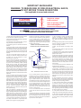
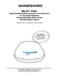
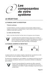
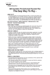
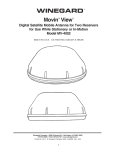
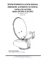
OPERATION/INSTALLATION MANUAL
WINEGARD AUTOMATIC RV DIGITAL
SATELLITE SYSTEM
Model AS-2003 & AS-2053
®
U.S. PATENT NO. 5,532,710
Made in U.S.A.
FOR SLOPED ROOFS:
Use Winegard’s RW-5000 roof wedge.
Winegard Company • 3000 Kirkwood St. • Burlington, IA 52601-2000
319/754-0600 • FAX 319/754-0787 • www.winegard.com
Printed in U.S.A. © Winegard Company 2003, 2005 2452005 Rev. 10/024/05
1
IMPORTANT SAFEGUARDS
WARNING: TO REDUCE RISK OF FIRE OR ELECTRICAL SHOCK,
DO NOT EXPOSE TO RAIN OR MOISTURE.
(Not applicable to mount and antenna)
Dangerous voltage
inside enclosure
CAUTION
RISK OF ELECTRIC SHOCK
DO NOT OPEN
Refer to operating, maintenance and safeguard
literature accompanying unit.
CAUTION: TO REDUCE RISK OF ELECTRICAL SHOCK,
DO NOT REMOVE COVER, NO USER-SERVICEABLE PARTS INSIDE.
REFER SERVICING TO QUALIFIED PERSONNEL
1. All the safety and operating instructions should
be read before the appliance is operated.
attention to cord at plug, convenience receptacle
and the point where cord exits from the appliance.
2. The safety and operating instructions should be
retained for future reference.
12. If an outside antenna or cable system is connected to this video product, be sure system is
grounded so as to provide some protection against
voltage surges and built-up static charges. Proper
method is shown below.
10B. If the appliance is equipped with a 3-wire
grounding-type plug, a plug having a third (grounding) pin, this plug will only fit into a grounding-type
power outlet. This is a safety feature. If you are
unable to insert the plug into the outlet, contact an
electrician to replace your obsolete outlet. Do not
defeat the purpose of the grounding-type plug.
11. Power-supply cord should be routed so that it
is not likely to be walked on or pinched by items
placed upon or against it, paying particular
³
10A. If the appliance is equipped with a polarized
alternating-current line plug (a plug having one
blade wider than the other) this plug will fit into the
power outlet only one way. This is a safety feature.
If you are unable to insert the plug fully into the
outlet, try reversing the plug. If the plug should still
fail to fit, contact an electrician to replace your
obsolete outlet. Do not defeat the safety purpose
of the polarized plug.
³
³
9. This video product should be operated only from
the type of power source indicated in electrical
rating printed on the appliance or power supply.
³
³
8. If slots, holes and openings are located in the
housing, they are provided for ventilation and to
ensure reliable operation of the video product and
to protect it from overheating. These openings
should never be covered. The openings should
never be blocked by placing the video product on
a bed, sofa, rug, or other similar surface. This video
product should never be placed near or over a
radiator or heat register. This video product should
not be placed in a built-in installation such as a
bookcase or rack unless proper ventilation is provided or the manufacturer's instructions have been
adhered to.
Electrical
Service
Equipment
³
7. Do not use this video product near water - for
example, near a bath tub, wash bowl, kitchen sink,
or laundry tub, in a wet basement, or near a
swimming pool, and the like.
Ground Clamp
Antenna Discharge Unit
(NEC Section 810-21)
Grounding Conductors
(NEC Section 810-21)
³
6. Do not use attachments not recommended by
the video product manufacturer as they may cause
hazards.
Antenna
Lead-in Wire
³
5. Unplug this video or audio product from the wall
outlet before cleaning. Do not use liquid cleaners
or aerosol cleaners. Use a damp cloth for cleaning.
EXAMPLE OF ANTENNA GROUNDING AS PER
NATIONAL ELECTRICAL CODE INSTRUCTIONS
³
4. All operating and use instructions should be
followed.
³
3. All warnings on the appliance and in the operating instructions should be adhered to.
Ground Clamps
Power Service Grounding
Electrode System
(NEC Art. 250, Part N)
NEC - NATIONAL ELECTRICAL CODE
13. An outside antenna system should not be
located in the vicinity of overhead power lines or
other electric light or power circuits, or where it can
fall into such power lines or circuits. When installing an outside antenna system, extreme care
should be taken to keep from touching such power
lines or circuits as contact with them might be fatal.
14. For added protection for this video product
during a lightning storm, or when it is left unattended and unused for long periods of time, unplug it from the wall outlet and disconnect the
antenna or cable system.
15. Do not overload wall outlets and extension
cords as this can result in a risk of fire or electric
shock.
16. Never push objects of any kind into this video
product through openings as they may touch dangerous voltage points or short-out parts that could
result in a fire or electric shock. Never spill liquid of
any kind on the video product.
2
17. Do not attempt to service this video product
yourself as opening or removing covers may
expose you to dangerous voltage or other hazards. Refer all servicing to qualified service personnel.
18. Unplug this video product from the wall outlet
and refer servicing to qualified service personnel
under the following conditions:
a. When the power supply cord or plug is damaged.
b. If liquid has been spilled or objects have fallen
into the video product.
c. If the video product, except for antenna mounted
preamplifiers and downconverters, has been exposed to rain or water.
d. If the video product does not operate normally by
following the operating instructions. Adjust only
those controls, when provided, that are covered by
the operating instructions. An improper adjustment of other controls may result in damage that
will often require extensive work by a qualified
technician to restore the video product to its normal operation.
e. If the video product has been dropped or the
housing has been damaged.
f. When the video product exhibits a distinct change
in performance - this indicates a need for service.
19. When replacement parts are required, be sure
the service technician has used replacement parts
specified by the manufacturer or have the same
characteristics as the original part. Improper substitutions may result in fire, electric shock or other
hazards.
20. Upon completion of any service or repairs to
this video product, ask the service technician to
perform safety checks to determine that the video
product is in proper operating condition.
21. Note to CATV system installer: This reminder
is provided to call the CATV system installer's
attention to Art. 820-40 of the NEC that provides
guidelines for proper grounding and, in particular,
specifies that the cable ground shall be connected
to the grounding system of the building, as close to
the point of cable entry as possible.
22. This product should be mounted to a wall or
ceiling only as recommended by the manufacturer.
23. The product should be situated away from heat
sources such as radiators, heat registers, stoves
or other products (including amplifiers) that produce heat.
Table of Contents
OPERATION
Introduction ...................................................................................................................................................... 4
Wallplate Control Panel ................................................................................................................................... 5
Interior One or Two Receiver Connection ....................................................................................................... 5
Automatic Operation ..................................................................................................................................... 5-8
Check Switch Routine ...................................................................................................................................... 8
INSTALLATION
Tools Needed ............................................................................................................................................ 3, 10
System Components, Specifications, Warranty Information ......................................................................... 10
Installation Requirements .............................................................................................................................. 11
Mounting Assembly on Roof ..................................................................................................................... 12-15
Mounting Interior Wall plate Controller .......................................................................................................... 16
Wiring... .......................................................................................................................................................... 17
PARTS
Antenna Parts ................................................................................................................................................ 18
Base Assembly .............................................................................................................................................. 19
Turret Assembly/Cover ............................................................................................................................ 20, 21
Trouble Shooting ........................................................................................................................................... 22
Parts included:
18” Reflector
Backup structure
Mount base/turret
Mount cover & bracket
Vent tube
Cable entry plate
Hardware
Cable
Interior wall plate controller
Surface mount box
Tools needed for installation:
Level
Tape measure
Phillips screwdriver
Electrical tape
Cutter
Electric or cordless drill
1/8” drill bit (for pilot holes)
7/16” wrench (for dish assembly)
5/16” socket/nut driver
1-1/2” hole saw (for cable entry hole)
Sealant compatible with roof material
(check with vehicle manufacturer for compatibility)
FCC PART 15 STATEMENTS
NOTE: This equipment has been tested and found to comply with the limits for a Class B digital device, pursuant to Part 15
of the FCC Rules. These limits are designed to provide reasonable protection against harmful interference in a residential
installation. This equipment generates, uses and can radiate radio frequency energy and, if not installed and used in accordance with the instructions, may cause harmful interference to radio communication. However, there is no guarantee that
interference will not occur in a particular installation. If this equipment does cause harmful interference to radio or television
reception, which can be determined by turning the equipment off and on, the user is encouraged to try to correct the interference by one or more of the following measures:
• Reorient or relocate the receiving antenna.
• Increase the separation between the equipment and receiver.
• Connect the equipment into an outlet on a circuit different from that to which the receiver is connected.
• Consult the dealer or an experienced radio/TV technician for help.
CAUTION: Any changes or modifications to this equipment not expressly approved by Winegard Company may
void the user’s authority to operate this equipment.
3
Introduction/How Does Digital Satellite TV Work?
Introduction
For Programming information call:
DISH NETWORKTM - 1-800-333-DISH (1-800-333-3474)
DIRECTV® - 1-800-DIRECTV (1-800-347-3288)
ExpressVu - 1-888-SKYDISH (1-888-759-3474)
Congratulations! You have an RV automated digital
satellite reception product — AS-2003. This unit,
used with your digital satellite receiver, will deliver
the best reception possible. Your new Winegard
digital satellite unit was designed for easy installation, setup and operation.
Your new Winegard RV Digital Satellite Unit is an
easy-to-install, easy-to-use satellite TV reception system. Because it mounts on the top of your
recreational vehicle, it goes where you go and provides quality reception of digital satellite signal in the
continental United States only. Check with your programming provider for exact coverage area.
How Does Digital Satellite System
TV Work?
Satellite programming originates from an “uplink”
facility on Earth — the facility receives many signals
from different sources, combines the signals digitally
and transmits to the satellites. The satellites (22,300
miles above Earth) receive the uplink signal, amplify
it and then transmit it back to earth in the Ku frequency band. This signal is received by your
satellite antenna whose shape reflects and concentrates the signal to the LNBF*
attached to the antenna. The
LNBF is located at the “focal
point” of signal reflection, that is,
the point at which the maximum
amount of signal is effectively
concentrated. The LNBF amplifies and
converts the signal to the 950 to 1450
MHz range. The signal is then passed
through a coaxial cable to the electronics box, then to the receiver where
individual channel selection and processing take place.
DIGITAL BROADCAST
SYSTEM SATELLITE(S)
HIGH POWER KU-BAND
DOWNLINK SIGNAL
WINEGARD AUTOMATIC
DIGITAL SATELLITE
SYSTEM ANTENNA
WINEGARD
SENSAR® ANTENNA
* Low Noise Block Converter Feed
UPLINK SIGNAL
TELEVISION
SET
RECEIVER
PROGRAMMING UPLINK
CONTROL CENTERS
4
Wall plate control panel description, wiring hookup diagrams
RED LEDs (4): Indicate mode
is in use
WINEGARD
OFF: Turns system power
off when pressed.
ON: Turns system power
on when pressed.
SEARCH: Acquires GPS
signal and locates desired
satellite signal.
ON
OFF
SEARCH/
MOVING
PARK
PARK: Puts dish in park
position.
AS-2003
SATELLITE SYSTEM
LED also lights when dish
is moving.
Interior connections for one and two receivers
ONE RECEIVER HOOKUP
TWO RECEIVER HOOKUP
Bundled coax
coming into
vehicle
Bundled coax
coming into
vehicle
+13.8 VDC Power
Connections
Secondary coax
(almond), not used for
single receiver setup
Primary
“Bright White”
coax, to receiver
9-wire cable, put into harness connector for
installation to back of
wall plate control panel
+13.8 VDC Power
Connections
Secondary coax
(almond), connect to
second receiver
Primary “Bright White”
coax, connect to
main receiver
9-wire cable, put into harness connector for
installation to back of
wall plate control panel
Wall Plate
Control Panel
•
Sat In
Wall Plate
Control Panel
•
TV set out
Sat In
•
TV set out
•
Receiver
Main
TV
TV
5
•
Sat In
TV set out
•
Primary
Receiver
TV
2
Second
Receiver
System Operation
BEFORE parking and leveling vehicle, look for trees,
buildings, hills or mountains that might block the satellite
signal and result in poor signal reception.
Wall Plate Control Panel
WINEGARD
ABOUT YOUR RECEIVER (The unit is factory preset
to find 119°W (DISH Network):
If you have a DISH NetworkTM receiver, be sure your unit
(AS-2003) is set to receive DISH Network satellites. If
you have a DIRECTV® receiver, be sure your unit
(AS-2003) is set to receive DIRECTV satellites. (The
majority of programming for DISH Network is on satellite
119°W; for DIRECTV, it is on 101°W.)
AS-2003 is factory preset to find 119°W (DISH
Network). You can contact DISH Network at 1-800-333DISH (1-800-333-3474) for programming information.
Contact DIRECTV at 1-800-DIRECTV (1-800-347-3288),
or ExpressVu (Canada and Northeast U.S.) at
1-888-SKY-DISH (1-888-759-3474).
OFF
SEARCH/
MOVING
PARK
AS-2003
SATELLITE SYSTEM
IMPORTANT! If you are using more than one receiver,
the primary (the “bright white” coax connection) is the
only receiver that will toggle between satellites.
LED ERROR CODES
Errors are indicated by LEDs.
OFF AND SEARCH LEDs are on.
Satellite signal search failure.
ON, PARK, SEARCH, OFF LEDs are on.
Indicates receiver is not plugged into
active 110 VAC, malfunction of receiver,
bad LNBF or bad coax connection.
ON, OFF LEDs are on.
Indicates a problem with the unit motor.
POWER MUST BE TURNED OFF AND
BACK ON TO CLEAR ERROR LIGHTS.
FIRST TIME USE:
The unit is factory preset to find 119°W (DISH Network). For DIRECTV, you must change the preset
switches on the outside unit. See Step 8 in Installation,
page 14.The first time your unit is used, allow 10 minutes
for GPS acquisition. (This is also true if you have stored
your unit for six months or longer. This is typical of first
time use; do not think there is a malfunction.
1. Turn TV on and tune to channel 3 or 4 (the output
of your receiver).
2. Turn on your primary receiver. The receiver MUST
BE TURNED ON and LNBF COAX PROPERLY
ATTACHED (refer to your receiver owner manual). If
not properly connected, all LEDs will be on.
3. To search for satellite, see Power On and Satellite
Search procedures, AS-2003 Control Panel
Operation instructions, page 7.
4. After search routine is completed and primary
receiver is at 119 (DISH Network), the unit may
switch between the primary and alternate satellite. A
Check Switch must be performed for toggling
capabilities on DISH Network. See Check Switch
instructions, page 8.
5. After the primary satellite signal is found and Check
Switch completed, the unit may be powered off. To
switch satellites, turn power back on and switch
satellites. The unit can then be turned off. The satel
lite signal last selected will still be “seen” by the dish
when the unit is turned on again.
6. To park your unit, see Parking procedures, AS-2003
Control Panel Operation instructions, on page 7.
ON
6
Control Panel Operation
Unit is off. All four LEDs are off.
2. After successful GPS acquisition,
WINEGARD
the ON LED will come back on
and the SEARCH LED will
ON
OFF
remain on, indicating the unit is
now moving in the search routine
SEARCH/
PARK
and actively seeking the desired
MOVING
AS-2003
satellites. When ON and SEARCH
SATELLITE SYSTEM
LEDs are on at the same time,
the unit is moving and searching. The search routine
can be stopped at any time by pressing the SEARCH
button or the PARK button; However, doing so will
return a SEARCH Error, turning the ON LED off and
the SEARCH and OFF LEDs on. The search can be
restarted by going to the beginning of SATELLITE
SEARCH procedure. The OFF button may also be
pressed to stop the search routine. The unit can be
restarted using SATELLITE SEARCH procedure.
WINEGARD
ON
OFF
SEARCH/
MOVING
PARK
AS-2003
SATELLITE SYSTEM
WINEGARD
POWER ON
1. Press the ON button on the
control panel. All four LEDs will
flash and the ON LED will
remain on.
ON
OFF
SEARCH/
MOVING
PARK
AS-2003
SATELLITE SYSTEM
2. After approximately 5 seconds,
all four LEDs will flash while the
unit is checking for proper
signal level. If all four LEDs
remain on, refer to the WALL
PLATE ERROR CODES,
page 22.
WINEGARD
ON
OFF
SEARCH/
MOVING
PARK
3. When the unit is finished
WINEGARD
searching and has stopped
moving, the SEARCH LED will
ON
OFF
go off automatically, leaving
only the ON LED still on. This
SEARCH/
PARK
MOVING
indicates the unit has comAS-2003
pleted a successful search. It
SATELLITE SYSTEM
will take approximately 4 to 5
minutes to complete a search routine after GPS acquisition. If the unit has stopped and any other
LEDs (besides the ON LED) are on, refer to the
WALL PLATE ERROR CODES on page 22.
(NOTE: If an error message shows on the TV
screen during initial search, the signal has been
lost. This is normal and means the dish has temporarily lost the signal but is still searching (peaking).)
Do not try to stop system!
AS-2003
SATELLITE SYSTEM
WINEGARD
3. After the signal is checked, the
ON LED and PARK LED will
remain on if the unit was last in
park position.
OR
The ON LED will remain on if
the unit was last in an upright
position.
ON
OFF
SEARCH/
MOVING
PARK
AS-2003
SATELLITE SYSTEM
WINEGARD
ON
OFF
SEARCH/
MOVING
PARK
PARKING
AS-2003
SATELLITE SYSTEM
SATELLITE SEARCH
WINEGARD
1. Press the SEARCH button
one (1) time. The SEARCH
ON
OFF
LED will come on and all other
LEDs will go off. This indicates
SEARCH/
PARK
MOVING
the unit is in search mode and
AS-2003
waiting for GPS acquisition.
SATELLITE SYSTEM
GPS acquisition time will
range from immediate to several minutes. (Important: Press the search button only once. Pressing
the SEARCH or PARK buttons in this mode will turn
the SEARCH LED off and the ON LED back on,
aborting the previous search. To restart, go to the
beginning of SATELLITE SEARCH procedure.
7
WINEGARD
1. If the unit is still powered on,
only the ON LED will be on.
ON
OFF
Press the PARK button two
times (2) to park the unit. The
SEARCH/
PARK
SEARCH and PARK LEDs will
MOVING
AS-2003
also come on,indicating the unit
SATELLITE SYSTEM
is moving to the park position.
(Important: If the unit has been turned off and on at
any time or the unit has been stopped using the
SEARCH or PARK button, it is only necessary to press
the PARK button one time (1), to park the unit.) Anytime the ON, PARK and SEARCH LEDs are on at the
same time, the unit is moving to the park position. The
park routine may be stopped anytime by pressing the
SEARCH button or the PARK button. Pressing either
button will turn off the SEARCH and PARK LEDs, leaving the ON LED still on. The park routine can be
restarted by pressing the PARK button one time (1).
The OFF button may also be used to stop
the park routine. The unit may be restarted going to
POWER ON procedure.
Control Panel Operation/Check Switch Routine
2. When the unit has finished the park routine, the SEARCH LED will automatically go off,
leaving only the ON and PARK LEDs still on. This indicates the unit is properly parked and
can be turned off. Before traveling, be sure the unit is in parked position. To be sure, step
outside and visually inspect before leaving your location.
NOTE: If the unit is raised and you want to put in park position, the satellite receiver
must be on and supplying voltage to the LNBF.
WINEGARD
ON
OFF
SEARCH/
MOVING
PARK
AS-2003
SATELLITE SYSTEM
Performing Check Switch routine to enable satellite toggle function used with
multi-satellite programming
AS-2003 will toggle between different satellites for the program provider you have. Both DIRECTV and DISH
Network have programming on more than one satellite.
When a channel is selected on the remote control and it is not located on the satellite the unit is currently on,
the system on the vehicle will automatically move to the new satellite. (When using multiple receivers, toggling
is controlled by the primary receiver. The primary receiver is connected to the dish with the white coax; secondary receiver if used, connects with the almond coax).
DIRECTV programming
1. There is some SETUP required for DIRECTV. You must select “Oval Dish 2 Satellites” in the receiver menu. To
change this, see Owner’s Manual for DIRECTV receiver. When you request a channel located on a different satellite,
the unit will automatically move to that satellite.
DISH Network programming (DISH 500)
4. If you still have an error, your vehicle may be parked
so satellites are on either side of the automatic stop
on the roof unit. The dish is unable to locate the
second satellite because it is forced to complete
almost a full revolution because of the stop. (See
illustration.) You can go outside and watch the dish
to see if this is happening.
NOTE: Once these steps have been completed, you
will not need to perform this test again, unless check
switch was performed on another satellite dish such
as a home dish.
1. Wait for unit to acquire the satellite signal on
satellite 119. (See search procedure, pp. 6-7.)
2. After signal has been acquired, 6 minutes remain to
complete Check Switch test; this 6 minutes will
expire with unit on or off. Consult DISH Network
receiver manual to perform Check Switch test.
The solution is to move your vehicle to a different
angle so the satellites are not located on either side
of the stop in the outside unit.
5. Your system is now set up to toggle between
satellites. It will automatically move to the correct
satellite when channel is selected.
3. During the Check Switch Test, the receiver will
begin checking your switch by toggling between
transponders. When this is completed, SW42 will
appear on the screen. It will be at the top of the
screen, satellite designations will be below, showing
odd and even transponders. See illustration below.
Stop interrupts Check
Switch operation
NOTE: If a switch other than SW42 appears, or you
have an X in one the of the boxes below the satellites, repeat Check Switch steps.
119
°
110°
SW42
110
119°
ODD EVEN ODD EVEN
110°
Built-in stop
(not visible)
Check Switch screen display
8
W
W
110
W
W
119 119
Stop does not interrupt
Check Switch operation.
Built-in stop (not visible)
INSTALLATION
Model AS-2003 & AS-2053
9
Parts/Specifications/Warranty
Parts included
18 “Reflector
Backup structure
Mount base/turret
Mount cover & bracket
Vent tube
Cable entry plate
Hardware
Cable
Interior wall plate control
Surface mount box
Tools needed for installation
Level
Tape measure
Electrical tape
Cutter
Phillips screwdriver
Electric or cordless drill
1/8” drill bit (for pilot holes)
7/16” wrench (for dish assembly)
5/16” socket/nut driver
1-1/2” hole saw (cable entry hole)
Sealant compatible with roof material (check
with your vehicle manufacturer for compatibility)
Dish Specifications
Electronics Specifications
Reflector Diameter .................... 46 cm (18")
Antenna height ..................................... 53 cm
Antenna width ...................................... 49 cm
Gain at mid-range
11.2 GHz .............................. 33.22 dBi
12.1 GHz .............................. 33.89 dBi
12.6 GHz .............................. 34.23 dBi
Effective aperture ................................. 46 cm
Aperture efficiency .................................. 73%
Cross polarization (on axis)... .............. -21 dB
Beamwidth at -3 dB ................................. 3.5o
Beamwidth at -10 dB ............................... 7.00
F/D Ratio ................................................. 0.59
Frequency Range ................ 10.95-12.75GHz
Offset angle............................................... 240
Gauge .................. 22 gauge galvanized steel
Finish: ........ Textured thermoset powder coat
Primary Power ............................. +13.8 VDC
Power Consumption .......................... 3 amps
Operating Temperature ......... -10° to +130°F
Humidity ....................... 90% noncondensing
Size .................. 4-1/2"W x 4-1/4"H x 1-3/4"D
Weight ..................................................... 1 lb.
Mount Specifications
Height Lowered .......................................... 8"
Height Raised ..................... 30" vertical max.
Roof space required .......... 40"L x 20"W min.
Turning diameter clearance ..................... 33”
Antenna Movement ................... 2 DC motors
Weight ................................................. 16 lbs.
Shipping Weight .................................. 20 lbs.
Carton ......... 27-3/4"L x 20-3/8"W x 10-3/4"D
10
Installation requirements
To install the Winegard Automatic Digital Satellite Dish,
check with your RV dealer or manufacturer. Your RV may
already be pre-wired for this system, and/or may have a reinforced roof area available.
FIGURE 1
27.80”
27.80
1. Choose a location on the roof that will allow the dish
to raise and rotate without interference from other
roof-mounted equipment.
2. Roof space required for operation is 40”L x 20”W
minimum. Refer to Figures 1, 2, 3 and 5 for operating
parameters.
3. The unit must be level for best operation. The unit may
be up to 2.5° off level. For the fastest, most reliable
operation, it should be as close to level as possible.
Use the hydraulic or manual leveling equipment on
your vehicle to level the roof as much as possible.
Before beginning installation: If the mounting area
is not level, you can use a roof wedge, Figure 4.
Winegard’s RW-5000 roof wedge corrects tilt
up to 3.7°. For units with severely sloping roofs,
more than one wedge may be needed. If the roof
wedge is too thick, use stainless or aluminum washers.
4. When choosing a location for the interior wall plate
control panel, consider wiring, ease of viewing wall
plate and distance from your television set.
19.18”
19.18
FIGURE 2
40.55”
8.00”
27.8”
12.75”
Rotate Axis
FIGURE 3
29.9”
CENTER ROOF LINE
FIGURE 5
FIGURE 4
33” DIAMETER
TURNING
28”
RW-5000 ROOF
WEDGE & GASKET
FRONT OF VEHICLE
11
VEHICLE ROOF
FIGURE 6
4” MINIMUM from
first clamp to
cable-entry plate
First cable
clamp here!
The length of this cable MUST BE 53 inches
from back of electronics housing to clamp. NO
CLAMPS ALONG THIS 53” LENGTH!
FRONT OF
VEHICLE
4”
Cable-entry
plate
20”
CENTER LINE
OF COACH
ROOF
DRIVER
SIDE
Cable-entry
plate
FIGURE 6A
Cable-entry
plate
FRONT OF
VEHICLE
PASSENGER
SIDE
Cable clamps every
12” from first cable
clamp
First cable
clamp here!
The length of this cable MUST BE 53 inches
from back of electronics housing to clamp. NO
CLAMPS ALONG THIS 53” LENGTH!
PASSENGER
SIDE
20”
CENTER LINE OF
COACH ROOF
DRIVER
SIDE
Cable-entry
plate
FIGURE 6B
The length of this cable MUST BE 53 inches
from back of electronics housing to clamp. NO
CLAMPS ALONG THIS 53” LENGTH!
First cable
clamp here!
CENTER LINE OF
COACH ROOF
FRONT OF
VEHICLE
Cable-entry
plate
Cable clamps every 12” from first cable clamp
PASSENGER
SIDE
20”
DRIVER
SIDE
12
Roof installation
1. Position the roof template on the vehicle roof and drill 1/8” holes for the screws. DO NOT drill clear
through into interior of vehicle. The screws fasten mount to the roof only. Be sure the roof can
securely hold system.
2. Place base plate gasket under the base before screwing unit down. Secure the base plate of the
motorized assembly to the roof using appropriate screws. DO NOT APPLY SEALANT AT THIS TIME.
Note: IF YOU ARE USING THE ROOF WEDGE (RW-5000), use the 3/16” gasket included with motorized mount under the roof wedge. Install 1/16” gasket included with the RW-5000 roof wedge between
mount and roof wedge. Longer screws are needed for installation when using roof wedge.
4. Partially unroll your bundled cable and gently remove any kinks.
CAUTION!! See illustrations on page 12. Cable MUST BE ROUTED AS SHOWN IN FIGURE 6, 6A,
and
6B to prevent cable wrap! If not routed correctly, you may STRIP GEARS!
5. Route cable assembly around the base of the unit, Figure 6. FROM THE BACK OF THE ELECTRONICS
BOX TO THE FIRST CLAMP MUST BE 53”!
6. Drill hole for cable entry in appropriate place. THIS MUST BE 4” MINIMUM FROM FIRST CLAMP! You
can also run cable to an existing cable entry hole that meets the same distance requirements (4” minimum), Figure 6A. Be sure cable from mount to entry point is not too tight when dish is in stow position. If
there is not enough slack in the cable, it will bind and prevent proper operation, or damage the
mount.
7. Cut the cable wrap approximately four (4) inches away frompoint where it enters the cable-entry plate,
Figure 7. This allows proper sealant coverage. Do not damage cables when cutting away the cable
wrap. (The cable wrap protects and keeps together in one unit the coaxial cable, electrical cable and
9-wire control cable.) After cutting, wrap the outer cable wrap with electrical tape as shown, Figure 7.
Push cable through cable entry point on roof. Do not damage cable. DO NOT APPLY SEALANT AT
THIS TIME.
8. Place cables in rounded slots on cable entry plate. Fasten down plate with screws provided.
DO NOT APPLY SEALANT AT THIS TIME.
FIGURE 7
Cable wrap. Cut 4” away
before putting under
cable-entry plate.
Coax cable
Interior wall plate control cable
(White, purple, blue, green yellow, orange, red, brown, black).
DO NOT CUT THIS CABLE IF
POWER IS HOOKED UP TO
UNIT. THIS WILL DAMAGE
ELECTRONICS AND VOID
WARRANTY!!
Electrical tape,
wrapped at cut line.
Coax cable
Power cable & conductor for “Antenna Up” warning (Red, black and
orange wires).
NOTE:
The “bright white” coax cable is the primary coax that will be connected to your main receiver. The other coax cable is the secondary coax for a second TV and receiver. See page
5, Operation section, for examples of one and two receiver setups.
13
Roof installation
EXTERNAL GPS INSTALLATION
GPS antenna
GPS wire
36” long
4” MINIMUM from
first clamp to
cable-entry plate
The length of this cable MUST BE 53 inches
from back of electronics housing to clamp. NO
CLAMPS ALONG THIS 53” LENGTH!
First cable
clamp here!
4”
FRONT OF
VEHICLE
Cable-entry
plate
PASSENGER
SIDE
20”
CENTER LINE
OF COACH
ROOF
DRIVER
SIDE
BEFORE BEGINNING INSTALLATION, REFER TO DRAWING
9. GPS antenna can be installed within 3’ of the first cable clamp. It must have
a clear view of the sky to operate properly, and should have a level location.
10. Install away from air conditioners, satellite antenna and mount, or any other
roof-mounted equipment.
11. Decide where your GPS antenna will be located. Clean roof area with an
approved cleaner for your roof material.
12. After placing the GPS in the desired location, do not secure. Test your
system before securing permanently.
13. To permanently secure the GPS antenna, carefully peel the backing off the
tape on the bottom of the unit, then press down on the roof.
14. To prevent movement of the GPS wire, secure with an approved sealant
every 6”.
14
14. Install the vent tube on the back of the mount
base (This is the side opposite the word
FRONT). The hole for the vent tube is shown in
Figure 8. CAUTION: DO NOT seal the hole in
vent tube. Put sealant around the outside of
the vent tube, approximately 1/2 inch from end.
Push the vent tube into the vent tube hole,
Figure 8. The sealant will seal the hole as you
push in. Leave approximately 2 to 2-1/2 inches
of the vent tube extending from the hole. DO
NOT APPLY SEALANT TO ANY SURFACES
UNTIL YOU TEST YOUR UNIT.
15. BEFORE YOU INSTALL THE BASE COVER,
you must SET THE SWITCHES in the outside unit.
Decide which programming you will be using.
This will determine how you set your switches.
To set the switches for the satellite used by your
programming provider, remove the small plate
on the side of the electronics box, Figure 9. You
will need a Phillips screwdriver.
FIGURE 8
Vent tube hole
Vent tube Sealant
1/2”
FIGURE 9
Remove to
set switches
The switches will appear upside down, numbers will be
counter-clockwise. Set numbers right to left.
For DISH
Network®
set to 119°.
For DIRECTV®
set switches
to 101°.
For ExpressVu®
set switches
to 092°.
16. After setting the switches, replace the small plate shown in Figure 9. Be sure to tighten securely;
the insulating material on the inside surface provides weather protection.
17. Install the base cover, Figure 10.
a. Place cover on unit.
b. Line up holes in cover to holes in
motor housing and electrical box.
Use COARSE THREAD
SCREWS to attach to MOTOR
HOUSING.
Use FINE THREAD SCREWS for
ELECTRICAL BOX.
Coarse Thread Screw
2160091
Fine Thread
Screw
2160090
FIGURE 10
>
>
TEST UNIT TO BE SURE IT OPERATES PROPERLY BEFORE YOU
APPLY ANY SEALANT!
Use a sealant compatible with your
roof material.
Shroud
2200732
Mount Assembly AS-2003
(partial view)
15
Mounting interior wall plate controller
Inside your vehicle, choose a convenient location for the wall plate controller. Consider wiring layout and distance from your television set. The wall plate uses the
nine-wire mulit-colored cable.
1. Strip end of each wire. Place in harness in the locations indicated in Figure 11. Be
sure there are no individual “strays” from the wires that are not in the slot. These
“strays” can interfere with operation.
2. After putting each wire in the appropriate slot, tighten the screw.
3. When all wires are in place in the harness end, plug this into the back of your wall
plate control panel, as shown in Figure 11. DO NOT plug in upside down or incorrectly; your unit will not operate, or you may cause irreparable damage. Note label
on
board to help with positioning of plug.
FIGURE 11
1. WHITE
2. PURPLE
3. BLUE
9. BLACK
4. GREEN
5. YELLOW
8. BROWN
6. ORANGE
7. RED
4. Mount the wall plate controller flush with the wall or inside a cabinet. Push the wire
harness through the hole, connect to the wall plate and secure screws.
You can also use the surface mount box (provided), Figure 12.
When using mount box, you may
have to knock out the portion
of the box indicated
by the dotted line in
Figure 12.
Surface Mount
Box for Wall
Plate Controller
FIGURE 12
Box can be
mounted two
ways, as shown.
16
Wiring
Wiring the system:
This unit requires a +13.8 VDC fused circuit. Unit draws up to 3 amps. The unit uses sophisticated microprocessor technology and needs “clean” (filtered) power to function properly.
DO NOT USE power designated to operate a +12 VDC lighting circuit from the converter, or a converter that does not have a battery connected to it, or any unfiltered converter! Damage to the
system could result!
If in doubt, contact your dealer or the manufacturer of your vehicle.
NOTE: See page 5, Operation section, of this manual for one and two receiver setups.
1. Make connection of the RED WIRE to +13.8 VDC (constant supply of power).
DO NOT HOOK UP ORANGE WIRE. This is for “Antenna Up” warning sensor
supplied by most RV manufacturer. DO NOT CONNECT ORANGE WIRE TO +13.8 VDC!
Connect the BLACK WIRE to the ground.
2. Connect the “BRIGHT WHITE” (PRIMARY) COAX CABLE to “Satellite In” jack on the
back of your receiver. The primary coax must be hooked to the electronics box. This
receiver controls the toggle function.
3. Connect the receiver “Out to TV” to the television.
4. Plug receiver into 117 VAC receptacle.
5. Connect the other cable to your second receiver/TV.
For proper operation:
1. To check for LNBF voltage, you must have your receiver connected to your
system. Lack of receiver or a bad connection at some point will result in the dish not
being able to lock on any satellite signal. All LEDs on wall plate control panel will be on until cor
rected.
2. Refer to the Operation Section to fully test the system!
Check Switch function and toggling between satellites
For a complete description of these functions, see Operation section.
17
Antenna
46 cm Reflector, White
P.N. 2745282
Dish Bolt(4)
P.N. 2160363
LB-6000: STANDARD
DUAL LNBF P.N. 2780199
Carriage Bolt
P.N. 2160353
Flange Nut 1/4-20
(not shown)
P.N. 2160228
Backup Frame
Roller
P.N. 2744912
•
P.N. 2200460
•
Cable Tie
Hex Head Bolt
1/4-20 xx 2.5"
•
Pivot Bracket
Feed Arm
P.N. 2160237
P.N. 2744946
Nylock Nut
P.N. 2744945
14 - 20
Screw #10-24 x 3/4 (4)
P.N. 2160196
Pin, 1/4 x 3.375" long
P.N 2160813
Vent Tube
(Not shown:
E-clip for 1/4" Pin
Clamp (2)
P.N. 5160818)
P.N. 2590343
4/04/03
18
P.N. 2200122
P.N. 2160220
(not shown)
Base Assembly
Worm Gear Plug
P.N. 3200045
O Ring
P.N. 2240029
Worm/Shaft Assembly
P.N. 2754099
Spring
P.N. 2160818
Spacer
P.N. 2160425
Azimuth Motor
P.N. 2665042
•
Motor Housing
P.N. 3200260
•
Motor Housing Gasket
P.N. 2240054
Elevation Motor
P.N. 2665041
Electronics
•
•
Screw (3)
P.N.
2160196
Gasket
P.N. 2240056
Turret Top
P.N. 3100737
Shaft Seal
P.N. 2200852
Pivot Shaft
P.N. 2590355
Button Head Screw (4)
P.N. 2160137
Rotate Gear
P.N. 2200469
Outer Bearing
P.N. 2590347
Turret Base
P.N. 3100730
Vent Tube
P.N. 2200122
Elevate Shaft Gear
P.N. 2200465
Inner Bearing
P.N. 2590348
Hub
P.N. 3100736
4/04/03
19
Turret Assembly
Elevate Motor
Gear
P.N. 2200466
Screw (2) P.N. 2160197
Rotate Stop P.N. 3712450
Spring P.N. 2160827
Shoulder Bolt
P.N. 2160355
Idler Gear
Screw P.N. 2160197
P.N. 2200467
Park Limit Sw. (Wh) P.N. 2400106
Screw P.N. 2160197
Rotate Limit Switch
P.N. 2400105
Pivot Bearing
(2)
P.N. 2200470
Elevating Gear
P.N. 2200471
Motor Screws
(4)
P.N. Rotate
2160197
Motor Gear
P.N. 2200468
Azimuth Switch Bracket
P.N. 3200261
Screw (4) P.N. 2160195
Dual Contact (4)
P.N. 2162003
Screw P.N. 2160197
Down Switch br. P.N.
3200263
Down Limit Switch P.N.
Screw P.N. 21601972400103 Green
Up Switch Bracket P.N.3200262
Up Limit Switch P.N. 2400104 (Blue)
Molex Plug
P.N. 2340131
6. Elevate Motor
Yellow
9. Elevate Motor
Yellow
8. Up Limit Sw.
Blue
12. Rotate Motor
Black
3. Down Limit Sw.
Green
2. Park Limit Sw.
White
Plug (See Detail)
1. Rotate Motor
Blue
Rotate Limit Switch
Black
5. Rotate Limit Sw.
Red
3
6
9
12
2
5
8
11
1
4
7
10
4. Elevate Motor
Blue
Park Limit Switch
Black
Rotate Motor
Brown
Elevate Motor
Brown
Up Limit Switch
Black
Down Limit Switch
Black
20
11. Rotate Motor
Red
10. Elevate Motor
Red
7. Elevate Motor
Black
Cover installation
Coarse Thread
Screw
2160091
Fine Thread
Screw
2160090
Shroud
2200732
21
Troubleshooting the system
WALL PLATE ERROR CODES
This section of your manual will help you
solve occasional problems with your unit. If
you cannot solve the problem after using the
suggestions in this section, contact the retailer or dealer where you purchased this unit,
or call Winegard Technical Support at 1/800/788-4417, Monday through Friday, 7:00 a.m.
to 4:00 p.m., Central Time.
OFF & SEARCH LEDs are on —
Satellite search failure. The unit has failed to see the
satellite(s) that are needed to determine the desired
satellite signal, or the unit was stopped during the
Search routine.
Solution
1. DBS (Direct Broadcast Satellite) satellite signals
are in the south to southwest part of the sky. Be
sure there are no obstructions (buildings, trees,
mountains, etc.) that will block some or all of the
satellite signals needed to determine the correct
satellite signal for you.
UNIT WILL NOT PARK
1. Check unit on roof. Be sure there are no obstacles on
the roof that prevent parking.
2. Was the PARK button on the wall plate controller
pressed the correct number of times? See Control
Panel Operation.
ON, PARK, SEARCH & OFF LEDs are on —
No LNBF power has been detected. The unit is not
getting the required LNBF power from the receiver.
3. For the unit to park, the satellite receiver must be
plugged into an active 120 VAC outlet, and the LNBF
power from the receiver must be connected to the
AS-2003. If this is not done, the unit will go to a “No
LNBF Power” error (ON, PARK, SEARCH, OFF
lighted) and will not park.
Solution
1. Be sure the satellite receiver is plugged into a
functioning 120 VAC outlet.
2. Check for 11-18 VDC at the LNBF. Disconnect coax
cable from LNBF and measure voltage between the
copper center conductor (+) and the connector (-).
There should be 11-18 VDC on this coax. If not
present, check all coax connection from this point to
the receiver. To check the output voltage at the
receiver, connect a good piece of coax to the
SATELLITE IN jack on the back of the receiver. DO
NOT insert test light or meter probes directly into the
receiver jack! You may enlarge the connector and
cause a poor connection when coax is reconnected.
3. For new installations, be sure no screws from cable
entry plate or clamps have penetrated the coax.
UNIT WILL NOT PASS “CHECK SWITCH”
FUNCTION (DISH Network only)
1. The receiver must report it is connected to a “SW42”
switch. If you don’t see this report, your receiver cannot
toggle between satellites. You may have to retest the
Check Switch function occasionally.
2. AS-2003 limits the rotation of the turret to prevent
damage to the cable assembly (diagram on page 8).
If the vehicle is parked in a location that forces the
unit to rotate all the way around each time it
searches for a satellite signal, the Check Switch
function will not be completed. Move your vehicle to
face the unit in a different direction.
ON & OFF LEDs are on —
A motor stall has occurred.
Solution
1. The unit has run into an obstacle on the roof while
attempting to elevate or rotate. Visually inspect.
2. Cable length on roof too short, causing restriction
while elevating or rotating. Check cable routing
diagram for correct length and cable clamping.
3. Broken or pinched motor encoder wires, resulting in
loss of encoder data.
3. Be sure the “primary” coax is connected to the
receiver that is operating the Check Switch routine,
and that no devices are inserted on this coax
between the satellite antenna and receiver.
IF THERE IS AN ERROR CONDITION,
CORRECT THE PROBLEM, THEN
TURN THE UNIT OFF AND BACK ON
TO CLEAR ERROR.
22
Testing Voltages to Check Electronics
1. WHITE
2. PURPLE
3. BLUE
9. BLACK
4. GREEN
5. YELLOW
8. BROWN
6. ORANGE
7. RED
CAUTION! Improper alignment of connector plug can cause system failure. USE
EXTREME CARE when making connection. Unit MUST BE DISCONNECTED
FROM POWER SOURCE before connecting.
Measuring voltages present at wall plate control will aid in determining damaged circuitry in
electronics housing.
Set voltage meter to DC and touch black meter lead (-) on meter to #9 screw terminal on wall plate
connector. (Black wire - ground)
Touch red meter lead (+) to each of the colored wires listed below.
1. White wire voltage range 4.8 VDC - 5 VDC.
(4.7 would indicate damaged circuitry in the electronics housing — replacement of electronics
housing needed.)
Symptom: Unit may not park.
2. Purple wire voltage range 4.8 VDC - 5 VDC.
(4.7 would indicate damaged circuitry in the electronics housing — replacement of electronics
housing needed.)
Symptom: Unit may fail to rotate or elevate.
3 - 6. Blue, green, yellow, orange. These wires should measure .5 VDC or 1.8 VDC, depending on
switch states.
7. Red wire will read supply voltage to the unit when wall plate is switched on.
8. Brown wire will read primary voltage supplied to unit (11 to 13.8 VDC)
9. Black wire is ground.
23
Warranty
Returned units damaged in shipping due to improper packing will be charged to the dealer/customer.
WINEGARD MOBILE PRODUCTS LIMITED WARRANTY
(2 YEARS PARTS; 1 YEAR LABOR)
Winegard Company warrants this product against defects in materials or workmanship for a period of two (2) years from the date of original purchase.
During year one (1) of such warranty, Winegard Company will also pay authorized labor costs to repair or replace defective products. No warranty claim
will be honored unless at the time the claim is made, Customer presents proof of purchase to an authorized Winegard dealer (to locate the nearest
authorized Winegard dealer, contact Winegard Company, 3000 Kirkwood Street, Burlington, Iowa 52601, Telephone 319-754-0600). It is Customer’s
responsibility to verify the date of purchase by returning the warranty card included with the product to Winegard within thirty (30) days of the purchase.
If a warranty card is not returned, Customer must provide proof of purchase with a dated sales receipt for the Winegard product to verify the product is
under warranty. If the date of purchase cannot be verified, the warranty period shall be considered to begin thirty (30) days after the date of manufacture.
If a defect in material or workmanship is discovered and the product is returned before the expiration of the Warranty Period, Winegard Company will (at
its option) either repair, replace or refund the purchase price of the product at no charge to Customer. Customer may mail or personally deliver the product
to Winegard Warranty Services (located at 3000 Kirkwood Street, Burlington, Iowa 52601, Telephone 319-754-0600). Customer must return the product
along with a brief description of the problem and provide Winegard Warranty Services with Customer’s name, address, and phone number. If the warranty
card is not on file for the particular product, Customer must also provide proof of purchase to verify the product is under warranty.
Alternatively, Customer may take the product to a Winegard Dealer for repair. If the warranty card is not on file for the particular product, Customer must
provide proof of purchase to verify the product is under warranty. If the product was installed by a Winegard Dealer and is brought to a Winegard Dealer
for repair prior to expiration of year one (1) of the Warranty Period, Winegard Company will cover the Winegard Dealer’s labor charges for warranty repairs,
provided the Winegard Dealer contacts Winegard Company in advance for pre-approval of the charges. Approval of the charges is in the sole discretion
of Winegard Company. If approval is denied, Customer must mail or personally deliver the product to Winegard Warranty Services.
This Limited Warranty does not apply if the product has been damaged, deteriorates, malfunctions or fails from: improper installation, misuse, abuse,
neglect, accident, tampering, modification of the product as originally manufactured by Winegard in any manner whatsoever, removing or defacing any
serial number, usage not in accordance with product instructions or acts of nature such as damage caused by wind, lightning, ice or corrosive environments
such as salt spray and acid rain.
RETURN AUTHORIZATION POLICY
A Return Material Authorization (RMA) is required prior to returning any product to Winegard Company or Winegard Warranty Services under this warranty
policy. Please call our Technical Services Department at (800) 788-4417 or send an e-mail to [email protected] to obtain the RMA number. Please
furnish the date of purchase when requesting an RMA number. Enclose the product in a postage-paid package and write the RMA number in large, clear
letters on the outside of the package. To avoid confusion or misunderstanding, shipments without an RMA number or unauthorized returns will be refused
and returned to Customer freight collect.
WINEGARD COMPANY DOES NOT ASSUME ANY LIABILITIES FOR ANY OTHER WARRANTIES, EXPRESS OR IMPLIED, MADE BY ANY OTHER
PERSON.
ALL OTHER WARRANTIES WHETHER EXPRESS, IMPLIED OR STATUTORY INCLUDING WARRANTIES OF FITNESS FOR A PARTICULAR
PURPOSE AND MERCHANTABILITY ARE LIMITED TO THE TWO YEAR PERIOD OF THIS WARRANTY.
In states that do not allow limitations on implied warranties, or the exclusion of limitation of incidental or consequential damages, the above limitations or
exclusions do not apply.
Some states do not allow limitations on how long an implied warranty lasts, or the exclusion of limitation of incidental or consequential damages, so the
above limitations or exclusions may not apply to you.
This warranty gives Customer specific legal rights. Customer may also have other rights that may vary from state to state.
SATELLITE RECEIVER WARRANTY:
See manufacturer’s limited warranty policy.
Rev. 10/24/05
Winegard Co. • 3000 Kirkwood St. • Burlington, IA 52601 • 319/754-0600 • Fax 319/754-0787 • www.winegard.com
24
2452005 Rev. 10/24/05