1
· UCD300jUMP400
Owner's Manual/Manual del Usario/Manual de L'Utilisateur
AM/FM/CD Receiver
Receptor AM/FM/CD
AM/FM/CD Ampli-Syntoniseur
UCD300/UMP400
Para obtener instrucciones en Espanol, dirijase a la pagina 20.
Pour des instructions en Francais, referez-vous a la page 38.
PREPARATION
Getting Started
It's a good idea to read all of the instructions
before beginning the installation.
Contents
Installation Instructions...................
.,' 3
Wiring
............... ....................
.... 5
Installing the Removable Faceplate
.. 6
Operating Instructions ..................
...... 7
.... 11
CD Player Operating Instructions.
MP3 Player Operation (UMP400) ........... 13
CD Changer Controls ............................ 14
Remote Control..... .................
..15
customer support line at 1-800-323-4815.
(U.S.A. and Canada only,)
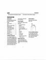
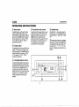
Tools and Supplies
Disconnect Battery
Before you begin, disconnect the battery
negative terminal.
The following tools and supplies are needed to
install the radio.
Torx type, ftathead and Philips
screwdrivers
Wire cutters and strippers
Tools to remove existing radio
(screwdriver, socket wrench set or other
tools)
------------
Electrical tape
Toll-Free Installation Assistance
Care and Maintenance ........................ 16
Specifications ........... ...................... .... 17
90 Day Limited warranty.
. .. 18
Crimping tool
Installation Requirements
18 gauge wire for power connections
This unit is designed for installation in cars,
trucks and vans with an existing radio opening.
In many cases, a special installation kit will be
required to mount the radio to the dashboard.
These kits are available at electronics supply
stores and car stereo specialty shops. Always
check the kit application before purchasing to
make sure the kit works with your vehicle. If you
need a kit but cannot locate one, call our
16-18 gauge speaker wire
Volt
meterltest light
Crimp connections
Speaker Requirements
Only connect speakers rated with a load
impedance of 4 ohms. Speakers with a load
impedance of less than 4 ohms could damage
the unit.
2
If you require assistance, contact Technical
Support at 1-800-323-4815 from 8:30 a.m. to
7:00 p.m. EST Monday through Friday and from
9:00 a.m. to 5:00 p.m. EST on Saturday.
(U.S.A. and Canada only.)
UCD300/UMP400
INSTALLATION INSTRUCTIONS
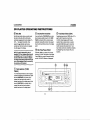
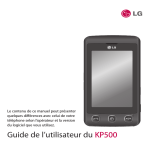
Installation Using a Mounting
5.
Sleeve
1.
2.
3.
4.
Slide the mounting sleeve off the chassis.
If it is locked into position, use the removal
tools (supplied) to disengage tl.
Check the dashboard opening size by
sliding the mounting sleeve into it. If the
opening is too small, carefully cut or file as
necessary until the sleeve easily slides
into the opening. Do not force the sleeve
into the opening or cause it to bend or
bow. Check for sufficient space behind the
dashboard for the radio chassis.
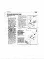
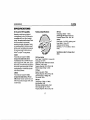
Locate the series of bend tabs along the
top, bottom, and sides of the mounting
sleeve. With the sleeve fully inserted into
the dashboard opening, bend as many of
the tabs outward as necessary to firmly
secure the sleeve to the dashboard.
Place the radio in front of the dashboard
opening so the wiring can be brought
through the mounting sleeve. Follow the
wiring diagram carefully and make certain
all connections are secure and insulated
with wire nuts or electrical tape. After
completing the wiring connections, turn
the unit on to confirm operation (vehicle
ignition must be "on"). If the unit does not
operate, re-check all wiring until the
problem is corrected.
6.
7.
Make sure the radio is right-side up, then
carefully slide the radio into the mounting
sleeve until it is fully seated and the spring
clips lock it into place.
Attach one end ofthe perforated support
strap (supplied) to the screw stud on the
rear of the chassis using the hex nut
provided. Fasten the other end of the
perforated strap to a secure part ofthe
dashboard either above or below the radio
using the screw provided. Bend the strap
to position it as necessary.
Test the radio using the Operating Instructions that follow.
CAUTION: The support strap
must be used to prevent
damage to the dashboard from
the weight of the radio or
Improper operation due to
vibration.
CAUTION: For proper operation
of the CD player, the chassis
must be mounted within 20° of
horizontal. Make sure the unit is
mounted within this limitation.
3
INSTALLATION
BEND TABS
UCD300jUMP400
INSTALLATION INSTRUCTIONS
Installation Using a Kit
ISO INSTALLATION
If your vehicle requires the use of an installation
kit to mount this radio, follow the instructions
included with the installation kit to attach the
radio to the mounting plate supplied with the kit.
1. Wire and test the radio as described in
step 4 of "Installation Using a Mounting
Sleeve" .
2.
3.
4.
ISO Installation
This unit has threaded hotes in the chassis side
panels which may be used with the original
factory mounting brackets of some Toyota,
Nissan, Mitsubishi, Isuzu, Hyundai and Honda
vehicles to mount the radio to the dashboard.
Please consult with your local car stereo
specialty shop for assistance on this type of
installation.
1.
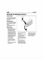
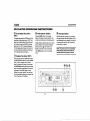
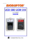
Removing the Radio
To remove the radio after installation, remove
the trim ring by lifting in the center and pulling it
offfrom either side. Insert the removal keys
straight back until they lock, then pull the radio
out. If removal keys are inserted at an angle,
they will not lock properly and will not release
the unit.
Install the radio mounting plate assembly
to the sub~dashboard according to the
installation kit instructions.
Attach the support strap to the radio and
dashboard as described in step 6 of
"Installation Using a Mounting Sleeve" .
Replace the dashboard trim panel.
Remove the existing factory radio from the
dashboard or center console mounting.
Save all hardware and brackets as they
will be used to mount the new radio.
reverse procedure in step 1 of "Installation
Using a Mounting Sleeve" .
2.
3.
Carefully unsnap the plastic frame from
the front ofthe new radio chassis. Remove
and discard the frame.
Remove the factory mounting brackets
and hardWare from the existing radio and
attach them to the new radio.
CAUTION: Do not exceed M5 X 6 MM screw
size. Longer screws may touch and damage
components inside the chassis.
4.
5.
Wire the new radio to the vehicle as
described in step 4 of ~Installation Using a
Mounting Sleeve" .
Mount the new radio assembly to the
dashboard or center console using the
4
REMOVING THE RADIO
'''''.:_>.
[~~
...... ~
........~..... .
(Q;~:> """~'"
UCD300/UMP400
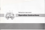
WIRING
..
~ ~ ~
tlCOOID IJ
coo
()~~
..
mE>
0
<)
c
... : :::.:,:::::
o
~
0
0
...
CD Changer
Connector
t
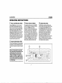
Antenna COilIlector
Power Antenna
Connect to power antenna
or amplifier. If not used. tape
bare end of wire.
Amplifier Wiring
Connect line out for optional
external amplifiers. The red
connector is for the right and the
white connector is for the left.
Ground
Connect to ground terminal.
Memory/Battery
Connect to battery or 12 volt
power source that is always
live. The radio will not work
if this wire is not connected.
WARNING! Never combine (bridge) outputs
for use with 1 speaker.
Accessoryllgnition
Connect to existing radio
wire or radio fuse.
WARNING! Never ground negative speaker
leads to chassis ground.
Fuses
CAUTION: Failure to wire exactly as shown
may cause electrical damage to the radio.
When replacing a fuse, make
sure the new fuse is the correct
type (ATO) and amperage,
Using an incorrect fuse could
damage the radio.
LRrARG
@)
5
UCD300/UMP400
INSTALLING THE REMOVABLE FACEPLATE
Faceplate Installation
To install the faceplate, slip the right edge olthe
front panel into the radio then gently press the
left side into place.
Faceplate Detachment
To remove the faceplate, press the RELEASE
... button, and pull gently on the left side olthe
front panel.
For safekeeping, store the front panel in the
protective case provided.
Handling Precautions
Make sure the front panel is right-side-up
when attaching it to the chassis as it
cannot be attached when up-side down.
Do not press very hard on the front panel
when attaching it to the chassis. No more
than light to moderate pressure is needed.
When attaching the front panel, make sure
it is centered in the chassis frame and is
pressed straight into position.
Do not drop the front panel.
Do not put pressure on the display or
control buttons when handling the front
panel.
Do not touch the electrical terminatson the
front panel or main unit.
Remove dirt or foreign substances with a
clean, dry cloth only.
Do not expose the front panel to extreme
temperatures or direct sunlight.
Keep volatile agents such as benzene,
thinner or insecticides away from the front
panel.
Do not disassemble the front panel.
When taking the front panel w'lth you,
please use the supplied carrying case to
protect the panel from dirt and damage,
6
Make sure there is no dust or dirt on the
electrical terminals on the back ofthe
panel as this could cause intermittent
operation or other malfunctions,
UCD300/UMP400
OPERATING INSTRUCTIONS
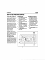
CD Power On/Off Button (PWR)
® Volume Control (AUDIO)
@
Press the PWR button (1) to turn the unit on
and off when the vehicle ignition switch is on.
When the unit is off, the clock is automatically
displayed on the Liquid Crystal Display (LCD)
panel unless the ignition switch is off. If the
radio is offwhen the ignition switch is turned off,
the PWR button must be pressed to turn the
radio on after the ignition switch is turned on. If
the ignition switch is turned off while the radio is
on, the radio will come on automatically when
the ignition switch is again turned on.
To increase the volume level, turn the AUDIO
control (3) clockwise. To decrease the volume
level, turn the AUDIO control counterclockwise. The volume will increase/decrease
and the level will be shown on display panel
from a minimum ofuVOL OO"to a maximum of
"VOL 100". The display will automatically return
to the normal indication 5 seconds after the last
volume adjustment or when another function is
activated. The AUDIO control is also used in
conjunction with the SEL button (4) to adjust
the bass, treble, balance and fader levels.
The SEL button is used to select the audio
function (volume, bass, treble, balance or fade)
to be adjusted using the AUDIO control (3).
Press the SEL button (4) once to set the unit for
volume adjustment (~VOL" will appear on the
display panel). Press the button additional
times to select bass adjustment (" BAS" on
display panel), treble adjustment (TRB),
balance (BAL), fader (FAD), and volume (VOL)
again. The display will return to the normal
indication 5 seconds after the last adjustment or
when another function is activated.
® Liquid Crystal Display Panel
The Liquid Crystal Display (LCD) panel displays
the frequency, time and all activated functions,
including a 5-bar graph which depicts the signal
level.
NOTE; It is a characteristic of LCD panels
that, ifsubjected to cold temperatures for an
extended period oft/mel they may take
longer to illuminate than under nonnal
conditions. In additlonl the visibility of the
numbers on the LCD may slightly decrease.
The LCD read-out will return to nonnal when
the temperature inside the vehicle increases
to a normal range.
3
4
7
Select Button (SEL)
UCD300/UMP400
OPERATING INSTRUCTIONS
o
Bass Control
To adjust the basslevel, first select the Bass
mode by pressing the SEL button (4) until
"BASH appears on the display panel. Within five
seconds, turn the AUDIO control (3) to adjust
the bass response from a minimum of "BAS 10" to a maximum of "BAS 10". ~BAS 00"
represents a flat response.
o
o
Front/Rear Fader Control
To adjust the front/rear speaker balance, press
the SEL button (4) until "FAD" appears on the
display panel. Within five seconds, turn the
AUDIO control (3) to adjust the balance
between the front and rear speakers from "FAD
10F" (full front) to "FAD 1OR" (full rear). "FAD
F=R" represents an equal balance level
between the front and rear speakers.
Treble Control
To adjust the treble level, press the SEL button
(4) until "TRB" appears on the display panel.
Within five seconds, turn the AUDIO control (3)
to adjust the treble from a minimum of "TRB 10" to a maximum of~TRB 10", "TRB 00"
represents a flat response.
o
left/Right Balance Control
To adjust the left-right speaker balance, press
and release the SEL button (4) until the "BAL"
indication appears on the display panel. Within
five seconds, turn the AUDIO control (3) to
adjust the balance between the left and right
speakers from "BAL 1OL" (fuJlleH) to "BAL 1OR"
(full right). "BAL L=R" represents an equal
balance level between the left and right
speakers.
3
4
8
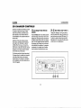
o
Audible Beep
Press SEL (4) for> 3 seconds to access the
Beep Tone menu. Turn the AUDIO control (3)
to select "BEEP ALL", "BEEP 2ND", or "BEEP
OFF".
® AM/FM Band Selector (BAND)
During radio play, each time the BAND button
(5) is pressed, the radio band changes. The
indications "AM 1", " F 1", "F 2", or"F 3" will
appear on the display panel according to your
selection.
UCD300/UMP400
OPERATING INSTRUCTIONS
® Loudness Control (BANDI
LOUD)
When listening to music at low volume levels,
this feature will boost the bass and treble
ranges to compensate for the characteristics of
hUman hearing. Press and hold the BANDI
LOUD button (5) to activate this feature as
indicated by a beep tone and "LOUD ON"
appearing on the display panel. ("LOU" remains
on the display.) Pressing and holding the button
again will sound a beep tone and display
"LOUD OFF". "LOU" will disappear.
® Tuning Control
Seek Tuning
Press the lUNEI1RACK (.. ,) button (6a) to
tune the radio higher, or the ruNE/TRACK
(<:""111) button (6b) to tune the radio lower. The
radio will seek the next strong station and stop.
Manual Tuning
To manually seek a specific station, first press
and hold either the up or down lUNEITRACK
button (6a and 6b) until "MANUAL" appears on
the display. Press the up or down ruNEI
TRACK buttons momentarily to tune two
frequency steps at a time.lf no further tuning is
performed after five seconds, "AUTO" will
appear momentarily on the display, and tuning
will revert to the original tuning mode.
(J)
FM Mono Select (MON)
® Local Button (LOC)
During FM radio operation, the MON button (7)
is used to select monaural or stereo reception
of the broadcast signal. Under normal reception
conditions, the unit should be left in the stereo
mode (indicated by "STEREO" when tuned to
an FM stereo signal). If the Signal is too noisy
for comfortable listening, press the MON
button; the "STEREO" indication will disappear
from the display panel and "MONO" will appear.
To return to stereo reception mode, press the
button again.
During radio operation, received signals are
usually in stereo mode as indicated by the "ST'
icon; however, when the signals are weak or
intermittent, you can activate the Local (LOC)
mode by pressing the LOC button (9)("LOC"
appears on the display). This mode favors
access to local stations whose signals are
much stronger; thereby improving radio
reception. Press the LOC button again to
terminate Local receive mode ("LOC"
disappears from the display panel).
® Auto-Store/Pre-Set Scan
@ Audio Mute (MUT)
(AS/PS or AMS)
Press the AS/PS or AMS button (8)
momentarily to scan the 6 stations in the preset memory for all FM bands. The unit will stop
at each pre-set station for 10 seconds. Press
AS/PS or AMS again to stop scanning and
select the current frequency. Press the AS/PS
or AMS button for more than 2 seconds to
activate the Auto-store Tuning feature. The
radio will automatically scan the band in use
and enter strong stations into the pre-set
memory positions for that band. Auto-store will
erase any stored stations.
9
Press the MUT button (10) to silence the
volume from the system. "MUTE" will appear on
the display panel. Press MUT again (or activate
another function) to return the volume level to
the setting that was in use before the Mute
function was activated.
UCD300/UMP400
OPERATING INSTRUCTIONS
® Station Pre-Set Memories
@
To set any of the 6 pre~set memory buttons,
use the following procedure:
the lUNEIlRACK buttons (6a and 6b).
This unit can display either the clock time or
radio frequency/CD player functions. Press the
DSP or DISP/O button (13) to display the time
for approximately 5 seconds. The correct timeof-day can be set by pressing and holding the
DSP or DISP/O button.
Press and hold a pre-set button until you
Setting the Clock
1.
Turn the unit on and select the desired
band.
2.
3.
Select the first station to be pre-set using
heara confirmation tone. The pre-set
number will appear on the display panel.
The station is now stored and can be re-
To
1.
called at any time by momentarily pressing
that button.
Repeat the above procedure for the remaining
5 pre-sets for the current band. Six stations can
be stored for each of the bands.
@
2.
Display Selector (DSP)
set the clock, perform the following steps:
Press the DSP or DtSP/O button (13) to
display the clock.
Press and hold the DSP or DtSP/o button
(13) until the time display flashes.
Equalizer Selector (EQ)
The EQ button (12) applies preset sound
effects to the unit's audio output signal. When
pressed, it will activate one of the following
modes: "FLAT', "CLASSICS", "POP M", "ROCK
M" or "DSP OFF". \lVhen the Equalizer function
is active, the bass and treble levels can still be
changed to accommodate the listener's ear.
VVhen the EQ function is not active, the unit
returns to the user-set bass and treble levels.
10
3.
4.
5.
Within 5 seconds, press the TUNE!
TRACK « .. ) button (6b) to adjust the
minutes to the desired setting.
Press the lUNE/TRACK (.. » button (6a)
to adjust the hour and the "AM"I"PM"
indication to the desired time.
Press the DSP or DISPJO button again to
return to radio frequency or disc play or
wait five seconds and normal operation
will resume automatically.
UCD300/UMP400
CD PLAYER OPERATING INSTRUCTIONS
@
Disc Slot
With the label surface facing up, gently insert
the disc into the slot until the soft-loading
mechanism engages and disc play begins. "5-Cop ---" will appear momentarily. Once
loaded, the (II') indication will become
animated and the track number and elapsed
time will appear in the display.
NOTE: The unit is designed for play of
standard 5" (12 cmJ compact discs only. Do
not attempt to use 3" (8 em.) CD singles in
this unit, either with or without an adaptor,
as damage to the player andlor the disc may
occur. Such damage will not be covered by
the warranty on this product
® Cue/Review Functions
@ Track Scan Select (SCN)
Press and hold the ruNEIlRACK (.. » button
During disc play, press the 2 SCN button (17) to
play the first 10 seconds of each track.
("S-SCN" will be displayed with the track
number). VVhen a desired track is reached,
press the 2 SeN button again to cancel the
function and play the selected track. Track
Scan mode can also be canceled by activating
the Repeat Play (18) or Random Play (19)
fUnctions.
(6a) to adVance rapidly forward or the ruNEI
lRACK
button (6b) to advance rapidly
backward. During either function, the elapsed
time of each track will be shown on the display
panel.
«"")
@
Disc Play/Pause Select
Press the 1 PAU or 1>111 button (16) to freeze
disc play. "S-PAUSE" will appear on the display.
Press 1 PAU or ..../11 again to resume disc play
and the "S-PAUSE" indication will disappear.
® Track Selector (TUNE/
TRACK)
The Track Select functions are used to quickly
access the beginning of a particular track. Each
time the ruNEIlRACK (.. » button (6a) is
pressed, the next higher track number is
selected, as shown on the display panel. Each
time the ruNEIlRACK
button (6b) is
pressed, the next lower track number is
selected, as shown on the display panel.
«"")
11
UCD300/UMP400
CD PLAYER OPERATING INSTRUCTIONS
@ Track Repeat Play Select
@ Mode Selector (MODE)
@ Disc Eject Button
(RPT)
Press the MODE button (14) to change
between CD player and radio operation. The
current mode is indicated on the display panel.
V\lhen the disc eject.!: button (20) is pressed,
disc play is stopped, the disc is ejected, and the
unit will change to radio operation. If the disc is
not removed from the unit within 15 seconds,
the disc will be re-Ioaded.
During disc play, press the 3 RPT button (18) to
repeat play of the selected track ("S-RPT' will
appear on the display penel). Play of the track
will continue to repeat until 3 RPT is pressed
again and the "S-RPT" indication disappears
from the display panel. Repeat Play mode can
also be canceled by activating the Track Scan
(17) or Random Play (19) functions.
@
Random Play Select (SHF)
During disc play, press the 4 SHF button (19) to
play the tracks on the disc in a random, shuffled
order ("S-SHF~ will appear on the display
panel). In Random Play mode, you can press
the lUNEITRACK buttons (6a and 6b) to select
tracks in a random order instead of the normal
progression. Press 4 SHF again to cancel
Random Play mode. Random Play mode can
also be canceled by activating the Repeat Play
(18) or Track Scan (17) functions.
During CD player operation, this button may be
used to change to radio without ejecting the
disc (the CD icon (,) will remain on the
display to show that a disc is still loaded).
Press MODE again to return to CD player
mode.
NOTE: To prevent a disc from accidentally
being damaged, always remove the disc
from the unit when disc play Is finished.
UCD300/UMP400
MP3 PLAYER OPERATION (UMP400)
This section applies to the UMP400 only.
Searching by Name
Searching the Root Directory
Instructions for lnsert/Eject, PlaylPause, Track
Selection, Cue/Review, Scan, Repeat, and
Random are the same for CD and MP3
operation. Please see the CD Player Operation
section for information about these topics.
1.
1.
2.
After inserting an MP3 disc, "MP3 T" and the
track number momentarily appear, followed by
the ID Tag (if supported). After these initial
indications, the track number and song title
4.
2.
3.
5.
alternately appear, with the song title scrolnng
right to left across the display.
Display Information
6.
Press the AMS button (8) twice to enable
directory or file name searching.
Use the AUDIO control (3) to select the
characters A-Z, _, -, +, and 0-9.
Press the SEL button (4) to confirm entry
of each character.
Press the BAND/LOUD/ENTER button (5)
to begin the search. If the selected entry is
a directory name, '" '" will be displayed.
Use the AUDIO control to select the song/
file in this directory/folder.
Press BAND/LOUD/ENTER to play the
selected song/file.
Press BAND (5 ) to display the 103 tag. if
available, The 10 tag can specify the song title,
artist, album, year and/or comments. If no JO
tag is available, "-NO 103" will appear in the
display following the comments.
Direct Song/ File Access
Press the AMS (8) button once to enable direct
track searching. Use the AUDIO control (3) to
select the desired song/file. Press the BAND/
LOUD/ENTER (5) button to play the selected
song/file, or do nothing and the unit wilt search
and play the song/file within three seconds.
13
3.
4.
5.
Press the AMS button (8) three times.
Use the AUDIO control (3) to select the
desired directory/song. If a directory is
present, "O-DIR" appears in the display.
Press the BAND/LOUD/ENTER button (5)
to access the directory. ", '" will appear
in the display indicating that a directory
has been selected for searching.
Use the AUDIO control to select the songl
file.
Press BAND/LOUD/ENTER to play your
selection.
UCD300/UMP400
CD CHANGER CONTROLS
Built into the UCD300 and UCD40Q are controls
to operate an optional CD changer. Please
check with your Phase Unear/AudiovQx car
stereo specialist or call1-800~323-4815 for
recommendations of the models that will work
with this radio.
Adjustment of the audio functions (volume,
tone, balancs, and fader) and CD fUnctions
(PauselPlay, SCN, SHF, RPT and TRACK
selection) for the CD changer operate in the
same manner as they do for radio play. See the
Operation and CD Player Operation sections
for infonnation about these topics.
@
CD Changer Mode Selector
(MODE)
Press the MODE button (14) to select operation
ofthe CD changer, as shown by "CDC" on the
display panel. Disc play will begin and the disc
and track number will be shown on the display
panel. If a new magazine has been loaded into
the changer, play will begin from the first track
of the first disc in the magazine. If a magazine
was already in the changer, play will resume
from the track on the disc previously in play.
The following controls will operate an optional
CD changer when it is installed and connected
to this radio. Refer to the owner's manual
included with the CD changer for instructions
on the installation and correct loading and use
of the CD magazine.
14
@, @
Disc Select (5CD-/6CD+)
These CD-I+ buttons (21 and 22) are used to
select the desired disc for play. To advance to a
lower number disc, press the 5 CD- button (21).
To return to a higher number disc, press the 6
CD+ button (22). The number of the disc in play
will be shown on the display panel.
UCD300jUMP400
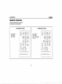
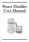
REMOTE CONTROL
The remote control will allow you to control the
basic functions of the UCD300/UMP400.
UCD300 REMOTE CONTROL
,,:
@ 8J8~8
~.~J /"'~\...... ".~:
~
(
MOD= MODE
BND = BAND
AMS = AS/PS
UMP400 REMOTE CONTROL
..
----- --
--,..-
PWR
MOD= MODE
BND = BAND
DSP = DISP (Display)
PAU =~III
.....
GYi
'8'
81.918
CD CD CD <3
I
~
(-TUNEfSEEK-,:
~
~~~"'-/;--~
..,' , /
PAU
SHF
0
seN
_.
/
~--"-'i
VOL
8i8~EK;Gj9
'~
VOl//~--
8 1,9:,'8
CD CD CD <3
PAU
SHF
/.---" ·DlSC" ~
(D .C~)
0
!
i
ENT
RP"!
..•.•.•,.
r- J
PWR
LOU
INFRARED REMOTE CONTROLLER
!l\...--
@ 8.J(~5i
8
'/.~
L__ .___ --!
seN
RPT
DSP
D-AUO
.~ -DISC· -~
0_(~)
INFRARED REMOTE CONTROLLER
-:::::~)
15
0
UCD300jUMP400
CARE AND MAINTENANCE
Your new radio/CD player does not require any
maintenance. However, proper understanding
of its use and handling will help you obtain
maximum enjoyment of its capabilities. We
recommend that you keep this manual for
reference on the many features of this unit as
well as how to set the clock. The following
points should be observed:
When cleaning the interior of the vehicle,
do not get water or cleaning fluids on the
unit.
The CD player is a precision instrument
and will not operate properly in extreme
heat or cold. If such conditions occur, wait
until the interior of the vehicle reaches a
normal temperature before using the
player.
If the temperature inside the player gets
too hot, a protective circuit will
automatically stop play of the disc. In this
case, allow the unit to cool before
operating the player again.
Never insert anything other than a 5" (12
cm) compact disc into the player as the
mechanism can be damaged by foreign
objects.
Do not attempt to use 3" (8 em) CD-Single
discs in this unit, either with or without an
adaptor, as damage to the player and/or
disc may occur. Such damage will not be
covered by the Warranty on this product.
When not using the disc player, always
remove the compact disc. Do not leave an
ejected disc sitting in the disc slot as this
can expose it to sunlight and other causes
of damage.
Do not attempt to open the unit chassis.
There are no user-serviceable parts or
adjustment points inside.
VVhen the vehicle warms up during cold
weather or under damp conditions,
condensation may appear on the lens of
the disc player. Should this occur, the
player will not operate properly until the
moisture has evaporated.
The unit is designed with a vibration
dampening CD mechanism to minimize
interruption of disc play due to normal
vibration. \fVhen driving on rough roads,
however, occasional sound skips may
occur. This will not scratch or damage the
disc and normal play will resume when the
rough conditions cease.
Handling Compact Discs
Dirt, dust, scratches and warping can cause
skips in the playback and deterioration of sound
quality. Please follow these guidelines to take
care of your compact discs:
16
Carefully wipe fingerprints, dust and dirt
from the disc's playing surface with a soft
cloth. VVipe in a straight motion from the
center to the outside of the disc.
Never use chemicals such as record
sprays or household cleaners to clean
CDs, as they can irreparably damage the
disc's surface.
Discs should be kept in their storage
cases when not in use.
Do not expose discs to direct sunlight,
high temperatures or high humidity for
long periods.
Do not stick paper, tape or labels on disc
surfaces.
RESET BUTTON
A Reset button is located behind the
faceplate on the left side (the front panel
must be removed to access the button). The
Reset function is provided to protect the
microprocessor circuitry and should only
be activated under the following
circumstances as it will erase the time and
pre-set memories: Upon initial installation
aflerallwiring is completed; If there is a
malfunction of any of the switches on the
unit, pressing the Reset button may clear
the system and return to normal operation.
UCD300/UMP400
SPECIFICATIONS
CD-R and CD-RW Capability
Technical Specifications
Depending on media type and method of
"recording/burning", some CD-RIRWs may be
incompatible with this unit. After "recording/
burning", the session must be closed. Please
refer to your software's recommended
procedures for closing a disc/session. Review
your recording software to familiarize yourself
with the correct "recording/burning" procedures.
AM Tuner
Tuning Range: 530kHz -1710kHz
Sensitivity @ 20dB Signal to Noise: 30uV
Frequency Response: 30Hz - 2kHz, -3dB
General
Power Supply: 11 to 16VDC, negative ground
Fuses: Battery -15 amp, ATO
20-pin quick-connect harness
Dimensions: 7" X 7" X 2" (178mm x 178mm x
51mm)
We recommend using the latest versions of
Specifications subject to change without
notice.
ROXIO™ or NEROTM burning software.
UCD300
This unit will only recognize the CODA
(Compact Disc Digital Audio) format
"recorded/burned" onto a CD-R/RW This unit
does not support .MP3, .WMA, .wAV, .OGG or
other formats. The CODA format is the standard
format of an "original store-bought" CD. VVhen
recording/burning a CO-R/RW make sure the
CDDA format is selected.
UMP400
This unit will only recognize the CODA
(Compact Disc Digital Audio), .MP3 and
.WMA formats "recorded / burned" onto a CDR/RW. This unit does not support .wAV, .OGG
or other formats.
CEA Power Ratings
Power Output: 13 watts RMS X 4 channels into
4-ohms @ < 1% TH D+N
Signal to Noise Ratio: 70dBA below reference.
(Reference: 1 watt, 4-ohms)
Frequency Response: 20Hz to 20kHz, -3dB
Reference Supply Voltage: 14.4VDC
CD Player
Signal to Noise Ratio: >7SdBA
Frequency Response: 20Hz to 18kHz, ·3dB
Channel Separation: > 55dB @ 1kHz
D/A converter: 1BitiCh
FMTuner
Tuning Range: 87.SMHz - 107.9MHz
Mono Sensitivity: 18dBf
SOdS Stereo Quieting Sensitivity: 20dBf
stereo Separation @ 1kHz: >30d B
Frequency Response: 30Hz to 12kHz, -3dS
17
UCD300jUMP400
90 DAY LIMITED WARRANTY
AUDIOVOX CORPORATION (the Company)
warrants to the original retail purchaser of this
product that should this product or any part
thereof, under normal use and conditions, be
proven defective in material or workmanship
within 90 days from the date of original
purchase, such defect(s) will be repaired or
replaced with new Of reconditioned product (at
the Company's option) without charge for parts
and repair labor. To obtain repair or
replacement within the terms of this warranty,
the product is to be delivered with proof of
warranty coverage (e.g. dated bill of sale),
specification of defect(s), transportation
prepaid, to the warranty center at the address
shown below.
This warranty does not extend to the
elimination of caf static or motor noise, to
correction of antenna problems, to costs
incurred for installation, removal, or
reinstallation of the product, or damage to
tapes, compact discs, accessories or vehicle
electrical systems. This VVarranty does not
apply to any product or part thereof which, in
the opinion of the Company, has suffered or
been damaged through alteration, improper
installation, mishandling, misuse, neglect,
accident, or by removal or defacement of the
factory serial number/bar code label(s) or
markings. THE EXTENT OF THE COMPANY'S
LIABILITY UNDER THIS WARRANTY IS
LIMITED TO THE REPAIR OR
REPLACEMENT PROVIDED ABOVE AND,IN
NO EVENT, SHALL THE COMPANY'S
LIABILITY EXCEED THE PURCHASE PRICE
PAID BY PURCHASER FOR THE PRODUCT.
This warranty is in lieu of all other express
warranties or liabilities. ANY IMPLIED
WARRANTIES, INCLUDING ANY IMPLIED
WARRANTY OF MERCHANTABILITY, SHALL
BE LIMITED TO THE DURATION OF THIS
WRITTEN WARRANTY. ANY ACTION FOR
BREACH OF ANY WARRANTY HEREUNDER
INCLUDING ANY IMPLIED WARRANTY OF
MERCHANTABILITY MUST BE BROUGHT
WITHIN A PERIOD OF 30 MONTHS FROM
DATE OF ORIGINAL PURCHASE. IN NO
CASE SHALL THE COMPANY BE LIABLE
FOR ANY CONSEQUENTIAL OR
INCIDENTAL DAMAGES FOR BREACH OF
THIS OR ANY OTHER WARRANTY,
EXPRESS OR IMPLIED, WHATSOEVER. No
person or representative is authorized to
assume for the Company any liability other than
expressed herein in connection with the sale of
this product.
Some states do not allow limitations on how
long an implied warranty lasts or the exclusion
or limitation of incidental or consequential
damage so the above limitations or exclusions
18
may not apply to you. This warranty gives you
specific legal rights and you may also have
other rights which vary from state to state.
U.S.A: Audiovox Corporation, 150 Marcus
Blvd., Hauppauge, NY 11788,1-800-323-4815
CANADA: Call 1-800-323-4815 for location of a
warranty station serving your area.
Audiovox Electronics Corporation
150 Marcus Boulevard
Hauppauge, NY 11788
1-800-323-4815
www.audiovox.com
©2005 Audiovox
v.01t505