1
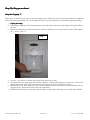
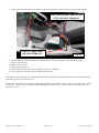
Maytag Ice2O French Door Refrigerator/Freezer Model
MFI2568AEW
HV Control
Control Board repair instruction guide
Note: This information is copyrighted material designed for non-commercial informational use,
and provided as-is with no warrantee whatsoever. Use at your own risk.
Symptoms:
•
Continuously flashing, blinking front panel display lights
•
Ice door flapping, clicking, opening and closing continuously
•
Lack of responsiveness to any button on the door
•
No ice or water dispenses
Optional Symptoms
•
Lights may only flash when compressor runs
•
Compressor may not run at all (fridge does not stay cold anymore)
Hello:
This guide describes my adaptation of a solution that was inspired by the Samurai Appliance Repair Man (SARM)
and a posting on the related appliance repair forum thread located at
http://applianceguru.com/view_topic.php?id=13035&forum_id=1&jump_to=75815 .
Since I found this info on the web for free, and you are finding this info on the web for free, if you find this helpful in
saving the +/- $350 repair bill or getting the fridge fixed faster than waiting on a new board (many reports of this are
back-ordered) please make the suggested donation of a “fin” to the SARM to help keep his free appliance repair
forum going. Tell him “Steve sent you” ;-)
What follows are two things: the unfortunately needed legal disclaimer on the conditions of using this info, and
lastly the actual description of what I did to fix my own fridge. Make no mistake, you will be fiddling with
components controlling wall-outlet levels of electricity, so if you haven’t ever done something like this, find a friend
who has or call in your local Maytag repair man.
In researching a fix for the fridge at 3am 7/5/07 after my fridge started the above symptoms, I located a number of
sites that had reference to this problem. The SARM actually had a description of a tech going to his friend with the
electronics shop and he repaired the board, it was re-installed, and seems to be working. Thus the inspiration for
my attempt, which as of the writing, is about 2 days running without problem.
I consider myself handy, and an electronics hobbyist, hence why I decided to try performing the work myself. That
plus I was looking at a minimum $300 repair bill to replace the HV Control Board and since it was going to be
replaced anyway, I was willing to spend $5 in parts to save the $300.
So without further delay, please carefully read BOTH sections, and good luck !
- Steve
© 2007 by Stephen Beck V1.0
Page 1 of 19
Use at your Own Risk
Important Safety Reminders and Legal Stuff – Don’t
on’t Skip:
Alas, with the litigious nature of this society, the following disclaimers and safety information are required and by
using any of the material in this guide, you agree to the following:
• This document is a guide to opening up your fridge and fiddling with it in a manner the manufacturer did
not intend a consumer to do so. Thus proceeding with these instructions could be DANGEROUS to the point
of ignoring warnings or taking needed precautions could result in damage, serious injury, OR DEATH.
DEATH
Perhaps this is a little melodramatic, but see the next bullet.
• You will be working with the part of the fridge that controls the wall outlet electrical power. While obvious
to most, UNPLUG THE FRIDGE BEFORE WORKING ON IT lest you electrocute yourself rendering the
repair moot.
• You will be required to perform a de-soldering operation removing 2 electronic components (capacitors) and
solder in 2 new ones. If you don’t know what soldering is, or you feel uneasy about what this might entail,
ask someone who has experience with this sort of thing (who has perhaps successfully assembled a Heathkit
or Velleman electronic kit).
• This document outlines a fix that appears to be common to this fridge make/model. It is possible that your
fridge make/model has something else/additional wrong with it and may need a different/additional repair.
• These instructions are provided as-is where-is with no warrantee whatsoever. You decide if this is fit for
your particular purpose and you assume all risks in doing so. Due to the variance of capabilities of the
individual reading this, and the possible failure modes of any electronic circuit, I can’t foresee that this
would be the correct course of action to take to repair your fridge without going thru an exhaustive set of
diagnostics using equipment you probably don’t have. If you want a 100% (99%?) sure thing, call in the
Maytag Repairman if you can pull him from fixing those toy machines on the new commercials. That’s why
it costs you a buck and a quarter to get him there – he has to pay for the tools and insurance that would
allow him to diagnose what’s wrong, or at least understand the whole board needs to be replaced and cover
the insurance should something go awry.
• It is quite possible that your fridge is broken to the point that this repair won’t work, or that further damage
to your fridge might occur either because of the repair or your attempt at the repair. If you are at all
concerned by this, STOP READING NOW and don’t bother with this procedure. Get the Maytag Repairman
in.
• You release me the author of this doc, and anyone who might distribute this info in part or in whole, from
any liability whatsoever related to, or resulting from the use of these instructions and/or diagrams, including
any incidental or consequential damages, whether you’ve told me about it or not. If your state or jurisdiction
does not allow for this, then you agree you should either a) stop reading now, throw this away, and not use
this guide; or b) I’ll limit my liability to you as the maximum of what you can prove you actually paid me for
this information; or the equivalent of US$0.01 whichever is higher, payable by any means I choose (might be
in Bolivars….), you pay postage.
• Soldering irons get REALLY, REALLY hot and can burn you in an instant. Grab the right end the first
time.
• The board you’ll be working on contains delicate electronic components that can be damaged by static
electricity. One static shock can make it an expensive paperweight. Wear cotton, avoid rubbing any body
part on the rug and the like to minimize the risk of static shock.
• Keep the kids away while you work unless yours can understand the dangers as well and can be relied upon
to follow both these instructions and yours to keep their fingers out of dangerous places. I think teaching
kids how to fix things passes on an excellent skill and can help reduce the ‘throw-away” nature of our
society.
• Be prepared to quickly unplug the fridge if something doesn’t look right: flames, smoke, sparks, loud noises
(from the fridge, not the kids), blown fuses or tripped breakers.
• Trademarks and products names are owned by their respective companies.
• This document and photos are copyrighted materials by me describing my experiences in repairing my
fridge. I grant you a non-exclusive right to use these materials to help you better understand your fridge as
long as the document stays in it’s original form, contains all copyright marks, and is not incorporated into a
larger work that is then used for commercial for-fee purposes (e.g. wind up in Maytag’s repair manual…).
• Above all, use common sense. If you’re not sure you have any, ask a true friend. If you know you have none,
borrow a friend who does.
© 2007 by Stephen Beck V1.0
Page 2 of 19
Use at your Own Risk
Overview:
Your job is to carefully remove 2 failed components from the main High Voltage (HV) Control Board– specifically 2
electrolytic capacitors (caps) - from an electronic Printed Circuit Board (PCB).
You will need to purchase replacement parts for this repair. Additionally, you will need equipment that is common
to any electronics hobbyist’s toolkit to de-solder defective parts and solder in new replacement parts. In order to get
the fridge fixed as fast as possible, I used readily available (to my area) replacement parts from Radio Shack (RS).
RS does not have the exact replacement parts that are used in the fridge, but they have items that are “close
enough” to use. If you don’t have a RS near you that stocks these parts, you’ll have to get them by mail order from
places like Jameco Electronics (www.jameco.com), or Mouser Electronics (www.mouser.com). I’ve ordered from both
them before and both are reliable parts vendors. From them, you can get exact replacements.
Technical stuff:
The problem with the fridge is that two electrolytic caps that are used to make a low voltage (12vDC like your car)
power supply over time get weaker and fail. These are 680uF (micro Farads) 35V units that level out the rectified
and now pulsing AC voltage from a transformer to a nice even DC voltage. This is a very common power supply
design. Capacitors store electricity and more info can be located on the Wikipedia at
http://en.wikipedia.org/wiki/Capacitor . The failure of these electrolytic capacitors as I saw in my fridge was typical.
They were hot to the touch even after power was turned off while the others were not, the tops were domed or
crowned, and after removal, they checked out dramatically lower in value than the label value of 680uF.
In looking at the PCB, I could determine that these were wired in parallel (see same Wikipedia link), and hence the
circuit was using these two capacitors adding up to a total of 680uF + 680uF = 1360uF. RS had in stock a 1000uF
and 470uF 35V units that could be similarly used 1000uF + 470uF = 1470uF. Since the caps had a 20% tolerance
(meaning the value could vary +/- 20% from the rating) this pair could have a value anywhere between 1176uF and
1764uF. This can be considered “close enough” in such a power supply design. Remember, the caps coming out also
have some +/- tolerance (my parts don’t show how much) but filters like this in power supplies are OK with a little
higher value.
So when the caps fail, the power supply starts to fluctuate at the same rate as the AC wall power frequency (60Hz in
the US) which can do one of two things: creates lots of electrical noise on the power supply that the fridge’s
microcontroller (computer) mis-reads as important information that it needs to act upon and hasn’t a clue how to, or
the power becomes so poor that the microprocessor thinks it’s just starting up from being plugged in and goes thru
it’s initialization sequence which seems to include an opening and closing of the ice door flapper. This then gets
repeated indefinitely while it’s plugged in, hence the flashing and flapping you see. Worst case is there is
insufficient power to pull in the relays that do things like start the compressor that keeps the fridge cold with the
obvious end results to the meat in your freezer. Have a Bar-B-Q with the neighbors so it doesn’t go to waste.
Whew.
© 2007 by Stephen Beck V1.0
Page 3 of 19
Use at your Own Risk
Parts and Supplies List
Parts needed:
(1) 1000uF radial lead electrolytic cap, Radio Shack P/N 272-1032 $1.59
(1) 470uF radial lead electrolytic cap, Radio Shack P/N 272-1030 $1.29
Total $2.89 + tax
If you don’t have soldering and de-soldering tools you’ll need these:
(1) de-soldering bulb, Radio Shack P/N 64-2086 $3.99
(1) pencil tip soldering iron, Radio Shack P/N 64-2051 $7.99
Note RS has many irons, this seems to be the cheapest
(1) Rosin core solder 64-017 $1.99
Total $13.97 + tax
Other stuff:
(1) ordinary sponge (buy a new one for the sink, cause you won’t want to use this for dishes ever again)
(1) 3-prong grounding extension cord (temporarily needed for testing)
(1) ABC rated fire extinguisher (a safety measure)
Rubbing alcohol
Q-Tipstm
So a complete kit will set you back around $20. Note prices are as seen on the Radio Shack web site as of 7/7/07 and
subject to change at RS’s whim.
Tools:
¼” socket and ratchet, or a ¼” nut driver,
(1) flat blade screwdriver (2 if you have them)
(1) set of extra hands of a helper from time to time
Pair of “diagonal cutters” – a type of wire cutter
© 2007 by Stephen Beck V1.0
Page 4 of 19
Use at your Own Risk
StepStep-ByBy-Step procedures
procedures:
Stop the flapping !!!
These steps are optional if you want to stop the flapping noise while you go get the parts, presuming the compressor
still runs and keeps the fridge cold. If the fridge no longer stays cold, skip these steps and just unplug the fridge
1. Unplug the fridge.
fridge
2. If the fridge still keeps cool, then perform the rest of the steps to disconnect the flapper door opener thing-ama-bob.
3. Remove the drip tray from the bottom of the ice/water dispenser recess on the front left door. This exposes
(2) ¼” screws. (Fig. 1)
Fig. 1
© 2007 Stephen Beck
4. Use the ¼” nut driver (or socket and ratchet) and remove the screws.
5. Understand that the upper part of this frame is held by a clip from behind that does not move. You need to
pull the lower part of the frame forward that will allow you to lift it up off the top clip. So…
6. GENTLY press the lower right side of the ice/water dispenser frame towards the center and forward to unsnap the frame. Repeat for the lower left side of the frame.
7. GENTLY lift the frame up and away from the fridge a couple inches allowing you to see the wires behind.
© 2007 by Stephen Beck V1.0
Page 5 of 19
Use at your Own Risk
8. Have your helper hold the frame while you unplug the small wire connector (Fig 2) from the PCB. This will
stop the power from going to the door flapper and ice dispenser.
View looking down from the top
of the ice/water dispenser
Power to flapper door
and water dispenser
9.
10.
11.
12.
© 2007 Stephen Beck
Fig. 2
Re-assemble the front door frame by hooking it to the top and gently pressing it back into place.
Replace the 2 screws to keep it from popping off.
Replace the drip tray
Plug the fridge back in. If the ice door flapper is in the open position, stick a CLEAN (white preferred, color
choice your decision) sock into the opening to prevent cold air from escaping.
© 2007 by Stephen Beck V1.0
Page 6 of 19
Use at your Own Risk
Fixing
Fixing the HV Control Board.
Remove the PCB
PCB from the fridge:
1. Start by rolling out your fridge from where it’s stashed. You’ll need to access the back of the fridge.
2. Unplug the fridge (if it’s not already). This is a Safety Step – don’t skip it.
3. Locate the metal cover plate and the (4) ¼” screws securing it at the corners (Fig 3):
Fig. 3
© 2007 Stephen Beck
4. Use the ¼” nut driver (or socket and ratchet) and remove the screws.
5. You should now be looking at the HV Control Board behind a hard clear plastic cover (Fig 4.):
© 2007 Stephen Beck
© 2007 by Stephen Beck V1.0
Fig. 4
Page 7 of 19
Use at your Own Risk
6. Understand the plastic cover is held in place by (2) unmovable tabs on the left (think of this as the hinge side
of a door) that will break if you try to move them, and a movable tab on the right (think of it as the door
latch) that can be pulled forward. See Fig 5:
Fig. 5
© 2007 Stephen Beck
7. Remove the clear plastic door by gently prying the right side loose, and swinging it out. Pull the door to the
right releasing the tabs on the left from their holes.
8. You should now be able to touch the PCB. The 2 failing/failed caps are on the upper part of the PCB, look
like cylinders and the top might be described as looking like Mercedes Benz ™ hood ornaments. They may
still even be warm to the touch vs. the other components. CAREFUL as they could also be pretty hot and
could burn your finger. (Fig 6)
Up
Two bad caps – to be replaced.
Possible curved top like a dome
One good cap.
Note flat top
© 2007 Stephen Beck
Fig. 6
9. Feel the tops of the caps. They should be flat except around the edges where the label curls around from the
side. If the top feels curved upwards like a dome, or if they were warm to touch vs. the other components,
they are probably bad. (also Fig. 6)
© 2007 by Stephen Beck V1.0
Page 8 of 19
Use at your Own Risk
10. Understand there are 4 wire connectors plugged into the circuit board that will need to be removed. They
are all removed in the same manner. You will want to either mark or draw a picture as to which connector
comes from what plug to make re-assembly easier. The wires are just the right lengths and naturally fit to
the proper connectors if you want to skip the pictures/labels. See Fig 7:
Behind
the
label
© 2007 Stephen Beck
Fig. 7
11. GENTLY depress the top of the lever in the middle of one of the connectors and pull the connector up off of
the PCB. You may have to GENTLY rock the connector back and forth (along the long side) to get the
connector off. (Fig. 8)
Release Clip. All 4
connectors similar
© 2007 Stephen Beck
Fig. 8
12. Repeat the above step for the rest of the connectors.
13. Understand that the PCB is held in place by a top and bottom plastic clips that can break, and the right side
tucks into a slot in the white plastic tub holding the PCB and wires. (Fig 9).
PCB hold-down clips
Fig. 9
© 2007 Stephen Beck
© 2007 by Stephen Beck V1.0
Page 9 of 19
Use at your Own Risk
14. Using your flat blade screwdriver, push the small fingers on one of the tabs away from the PCB and using
your finger, or the 2nd flat blade screwdriver, GENTLY pry the side of the PCB toward you enough to clear
the fingers on the tab. (Fig 10)
© 2007 Stephen Beck
Fig. 10
15. Repeat the last step for the 2nd tab holding the PCB in place
16. GENTLY and evenly pull the left hand side of the PCB towards you and out of the clip, then slide it out from
the slot on the right hand side. (Fig 11)
Fig. 11
© 2007 Stephen Beck
17. Mark the right hand side with a bit of tape or marker so you know which side is what come re-assembly
time.
18. You should now have the PCB free in your hands unattached to the fridge. (Yay!)
Cautionary Note: The PCB contains delicate electronic parts that can be damaged by static electricity. When
handling it, take precautions to minimize the risk of generating a static charge lest you damage the board. So, no
scuffing your feet on the rug, rubbing a balloon on your shirt, or other shenanigans. If you have an electronics
grounding strap made for this purpose (the kind that drains thru a resistor, not a bare copper wire bonded to the
cold water pipe), wear it.
© 2007 by Stephen Beck V1.0
Page 10 of 19
Use at your Own Risk
Replace the Caps:
1. Take a close look at the caps. Mine showed a domed top which can be seen from the side view of the board.
(Fig 12) Yours may or may not look like this, but you can see which caps you’ll need to replace in this figure.
© 2007 Stephen Beck
Failed Caps
Domed tops
Good Cap
Flat top
Fig. 12
2. Turn the board over and locate the solder connections to the 2 failed caps. Note the “positive” and “negative”
connections which are important when you go to put the new parts in place. (Fig 13)
Positive
(+)
terminal
Negative
(-)
terminal
Failed caps solder side of PCB
© 2007 Stephen Beck
© 2007 by Stephen Beck V1.0
Page 11 of 19
Fig. 13
Use at your Own Risk
3. This is where you’ll need to get help from a friend if you don’t know how to solder. Read this description
fully before starting.
4. Using your soldering iron, and de-soldering bulb for suction, one cap at a time, melt each connection, squeeze
the bulb, and place it right on the molten solder and quickly un-squeeze the bulb while keeping it in place.
This acts like a mini vacuum cleaner and removes the solder from the connection. You may have to do this a
couple times to get as much solder off as possible. If the bulb gets clogged poke it clear with a toothpick or
small nail. Don’t keep the soldering iron on too long as it may damage the PCB.
5. With most of the solder removed, re-heat the 2 connections until the solder melts and then gently rock the
cap back and forth from the other side pulling the cap out. You may have to heat one connection at a time
and pull the cap up on that side. You may also need a helper to hold the PCB and pull on the cap for you.
Be careful not to burn your friend (perhaps they should be wearing heavy work gloves just in case..). I don’t
have a picture of this since it required all my hands and fingers to get it off, leaving none for the camera.
6. With the cap removed, if there is an open hole, great. If there is still solder in the hole, find a toothpick, reheat the hole till the solder melts, then gently stick the wooden toothpick through the hole, remove the
soldering iron and let it cool. Once the solder hardens, remove the toothpick. Remember that just because
the solder is hard does not make if safe to touch – it’s still quite hot. Blowing on it speeds the cooling
process..
7. You should be left with 4 holes in the PCB and 2 caps apart from the PCB.
8. Electrolytic caps have a “plus” (+) and a minus (-) just like your car. And just like your car, if you hook them
up backwards, dire things happen. So look at the caps you took out, and are about to put in. You’ll see a
“minus sign” or dash on one side. The wire coming out next to the minus side is the negative. The opposite
is the positive. (Fig 14) One of the new RS caps is on the right. (Fig 15) Same type of marking, slightly
different color combinations. See the arrow in the marking pointing to the bottom of the cap and the actual
wire lead.
Negative (-)
terminals
Negative (-)
terminal
Minus
sign
Minus
signs
Minus
signs
Fig. 15
Fig. 14
© 2007 Stephen Beck
© 2007 Stephen Beck
9. With the “minus” lead of the caps towards the center of the board, push the wire leads thru the holes and
seat the cap flat on the PCB. You can bend the wire leads out 45o to hold the caps in place for when you turn
the PCB upside down. Note that it does not matter which cap goes into either set of holes, only that the
positive leads go into the holes towards the edge of the board, and the negative leads go into the holes
towards the middle of the board.
© 2007 by Stephen Beck V1.0
Page 12 of 19
Use at your Own Risk
10. A view of the caps inserted in the PCB. Note that the negative or “minus” side of the caps and their
“dashed” markings are facing away from you. Also note the “plus” sign written on the PCB. (Fig 16)
Minus
signs
on
caps
Plus signs on PCB
Fig. 16
© 2007 Stephen Beck
11. Solder the 4 wire leads on the same side of the PCB you de-soldered. This is a critical step, so if you’re not
sure on how to solder, find someone who does. A bad solder joint here can make the connection useless.
12. Use your wire cutters to cut off the leads just above the solder connection. With any luck or skill, your
connections should look like this. (Fig 17)
Fig. 17
© 2007 Stephen Beck
© 2007 by Stephen Beck V1.0
Page 13 of 19
Use at your Own Risk
13. Clean the PCB with the Q-Tips and rubbing alcohol. This removes the residue that came out of the solder
when you heated it. Check to be sure that you don’t have any solder blobs bridging the gap between the
brown sections of the board. If you do, re-melt the solder and remove the bridge using the de-soldering bulb.
You should be able to see a clear green line between the positive and negative sides of each cap you soldered.
(Fig 18)
© 2007 Stephen Beck
Check
for, and
remove
solder
bridges
across
here
Fig. 18
14. The completed board looks like this on top. (Fig 19)
© 2007 Stephen Beck
Fig. 19
15. Well, if all looks the same on the solder side as when you first started, and you haven’t had to reach for the
burn cream, give yourself and your helper (if you have one) a pat on the back. You’re well on your way to
being able to get the fridge back together and cooling off a refreshment of your choice. ☺
© 2007 by Stephen Beck V1.0
Page 14 of 19
Use at your Own Risk
ReRe-install the PCB:
1. Installation is the reverse order of removal
2. Tuck the right hand side of the PCB (the one you marked, right ?) into the slot on the right hand side of the
white plastic tub. (Fig 20)
Fig. 20
© 2007 Stephen Beck
3. GENTLY press the left side of the PCB into the top and bottom clips till they snap closed, securing the PCB
in place. (Figs. 21 & 22)
Fig. 21
Fig. 22
© 2007 Stephen Beck
© 2007 Stephen Beck
4. Re-attach the wire connectors to the PCB – they should naturally fall back into the proper place to connect
back, and match your markings drawings you made when you took them off. Push the wires back into the
chases alongside the PCB. (Fig 23)
Fig. 23
© 2007 Stephen Beck
© 2007 by Stephen Beck V1.0
Page 15 of 19
Use at your Own Risk
5. GENTLY place the (2) small tabs on the clear plastic cover into the slots on the left hand side of the opening
for the PCB (Fig 24)
Fig. 24
© 2007 Stephen Beck
6. GENTLY close the clear plastic cover, engaging the latch on the right hand side.
7. You are now ready to test the fridge. (Yay again !) ☺
© 2007 by Stephen Beck V1.0
Page 16 of 19
Use at your Own Risk
Testing the Fridge (CAUTION REQUIRED):
REQUIRED):
1. Since this guide was written for an audience that might have minimal tools as opposed to a host of bench
test equipment, “testing the fridge” entails essentially “plugging it in”. THIS IS THE MOST DANGEROUS
STEP IN THE PROCESS as I can’t tell how well you’ve done your repair or re-assembly, so you should
carefully re-read the Important Safety Reminders section. Your helper should be at the breaker box ready to
turn off the power to the outlet you’re about to plug the fridge into. My apologies if this sounds
melodramatic, but I have no idea what you’re capable of doing, or whether there is something else wrong
with your fridge that can cause something else to happen. Remember, you’re here because you’re willing to
try a $20 repair to attempt to save >$300. If this step now gives you butterflies in your stomach, CALL THE
MAYTAG REPAIRMAN.
2. With your helper within ear-shot of your voice command to “turn off the power” if needed, plug the extension
cord into the outlet.
3. Pull the fridge plug and extension cord socket to the side of the fridge away from the PCB so you can easily
unplug it in a hurry if you need to.
4. Understand you need to look at the PCB and listen to the fridge for proper operation the moment you plug it
in. Any signs of sparks, smoke, fire, melting insulation or plastic or any other general mayhem should alert
you to unplug the fridge immediately. If you can’t unplug it, call to your helper to trip the breaker.
5. CAREFULLY plug the fridge in. Look for any signs of sparks, smoke, fire, melting insulation or plastic. If
any are suspected, UNPLUG THE FRIDGE IMMEDIATELY. Either you didn’t perform the repair correctly,
or the fridge needs other repairs and you’ll have to call in the repairman (such was the possibility you
understood before you started).
6. If the fridge is running properly, and the display shows the correct set temps, you’re good to go ☺
7. Unplug fridge.
8. Re-install the metal cover over the clear plastic cover and replace the (4) ¼” screws.
9. If you didn’t disconnect the flapper door, plug the fridge in again and push it back into place. You’re done.
Congratulations.
© 2007 by Stephen Beck V1.0
Page 17 of 19
Use at your Own Risk
Optional: Plug the flapper door back in:
1. Unplug the fridge.
2. Remove the drip tray from the bottom of the ice/water dispenser recess on the front left door if needed. This
exposes (2) ¼” screws (Fig. 25)
Fig. 25
© 2007 Stephen Beck
3. Use the ¼” nut driver (or socket and ratchet) and remove the screws.
4. Understand that the upper part of this frame is held by a clip from behind that does not move. You need to
pull the lower part of the frame forward that will allow you to lift it up off the top clip. So…
5. GENTLY press the lower right side of the ice/water dispenser frame towards the center and forward to unsnap the frame. Repeat for the lower left side of the frame.
6. GENTLY lift the frame up and away from the fridge a couple inches allowing you to see the wires behind.
© 2007 by Stephen Beck V1.0
Page 18 of 19
Use at your Own Risk
7. Have your helper hold the frame while you plug the small wire connector back into the PCB. (Fig 26)
View looking down from the top
of the ice/water dispenser
Power to flapper door
and water dispenser
8.
9.
10.
11.
12.
13.
© 2007 Stephen Beck
Fig. 26
Re-assemble the front door frame by hooking it to the top and gently pressing it back into place.
Replace the 2 screws.
Replace the drip tray.
Plug the fridge back in.
Check the operation of the water dispenser and the ice dispenser.
If everything checks out, push the fridge back into place.
I hope this document has proven a light and interesting read, and has possibly helped you better understand how
your fridge operates (or fails to do so).
As any of you who have been exposed to Boy Scouts will know, one should always seek to “Do a good turn”. Here’s
one of mine. Now you go out and do something helpful for someone else. And if everyone did that, it will be a
nicer place to live.
© 2007 by Stephen Beck V1.0
Page 19 of 19
Use at your Own Risk