1
TBII-4
J30-08867
INSTALLATION INSTRUCTIONS AND PARTS IDENTIFICATION
TUBULAR GAS-FIRED BLOWER STYLE UNIT HEATER
ATTENTION: READ THIS MANUAL AND ALL LABELS ATTACHED TO THE UNIT CAREFULLY BEFORE
ATTEMPTING TO INSTALL, OPERATE OR SERVICE THESE UNITS! CHECK UNIT DATA PLATE FOR TYPE OF GAS
AND ELECTRICAL SPECIFICATIONS AND MAKE CERTAIN THAT THESE AGREE WITH THOSE AT THE POINT OF
INSTALLATION. RECORD THE UNIT MODEL AND SERIAL No.(s) IN THE SPACE PROVIDED. RETAIN FOR FUTURE
REFERENCE.
Unit No.
Serial No.
FOR YOUR SAFETY
The use and storage of gasoline or other flammable vapors and liquids in open containers in
the vicinity of this appliance is hazardous.
FOR YOUR SAFETY
If you smell gas:
1. Open windows.
2. Don't touch electrical switches.
3. Extinguish any open flame.
4. Immediately contact your gas supplier.
ERTEK
INT
CM
VER
IFIE D
ENERGY
PERFORMANCE
VERIFIED
RENDEMENT
ENERGETIQUE
VERIFIE
Improper installation, adjustment, alteration, service, or maintenance
can cause property damage, injury, or death. Read the installation, operating, and
maintenance instruction thoroughly before installing or servicing this equipment.
APPROVED FOR USE IN CALIFORNIA
Install, operate, and maintain unit in accordance with the manufacturer's
instructions to avoid exposure to fuel substances, or substances from incomplete
combustion, which can cause death or serious illness. The state of California
has determined that these substances may cause cancer, birth defects, or other
reproductive harm.
INSTALLER'S RESPONSIBILITY
Installer Please Note: This equipment has been test fired and inspected. It has been
shipped free from defects from our factory. However, shipment and installation
problems such as loose wires, leaks, or loose fasteners may occur. It is the installer's
responsibility to inspect and correct any problem that may be found.
RECEIVING INSTRUCTIONS
Inspect shipment immediately when
received to determine if any damage
has occurred to the unit during
shipment. After the unit has been
uncrated, check for any visible
damage to the unit. If any damage
is found, the consignee should sign
the bill of lading indicating such
damage and immediately file claim
for damage with the transportation
company.
01/15
260 NORTH ELM ST., WESTFIELD, MA 01085
TEL: (413) 568-9571 FAX: (413) 562-8437
www.mestek.com
TABLE OF CONTENTS
DESCRIPTION………………........................................ 2
GENERAL SAFETY INFORMATION
Installation Codes………………………………… 2, 3
Special Precautions………………………………. 2, 3
PERFORMANCE AND DIMENSIONAL DATA.............. 4
INSTALLATION
Locating Units…………………………………………5
Combustion Air……………………………………… . 5
Heat Throw Data……………………………………. . 6
Clearances…………………………………….. ......... 7
Suspension of Units………………………………..... 7
Gas Piping……………………………………… ........ 8
Pipe Installation……………………………………. ... 9
BLOWER SET UP AND ADJUSTMENT……………... 10
MOTOR AND PULLEY .............................................. 11
ELECTRICAL CONNECTIONS…………………....12-16
VENTING ..............................................................17-22
OPERATION
Explanation of Controls…………………………… . 23
Start-Up, Shut Down………………......…………....23
Main Burner Orifice Schedule…………….……….23
Gas Input Rate and Adjustments…………….. 24, 25
TROUBLESHOOTING GUIDE ..............................26-29
LED Indicator Troubleshooting .............................. 30
MAINTENANCE… ...................................................... 31
WARRANTY…............................................................ 32
IDENTIFICATION OF PARTS ................................33-34
UNIT NUMBER DESCRIPTION ................................. 35
START-UP INSPECTION SHEET............................... 36
NOTICE: It is the equipment owners responsibility to provide any scaffolding or other apparatus required to
perform emergency service or annual/periodic maintenance to this equipment.
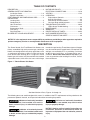
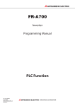
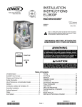
DESCRIPTION
The Power Vented Gas Fired Blower Unit Heaters are
factory assembled, high static pressure type, centrifugal
blower units designed for heavy duty applications such
as continuous operation or where a single unit heater
must do the entire heating job in a large area.These
blower type unit heaters may be used with the standard
adjustable louvers, with short duct runs or discharge
nozzles for spot heating. These blower type unit heaters
may be used where low sound levels are required. The
designs are certified by ETL as providing a minimum
of 82% thermal efficiency, and approved for use in
California. Do not alter these units in any way. If you
have any questions after reading this manual, contact
the manufacturer.
Figure 1 - Tubular Blower Unit Heater
See Identification of Parts, Figures 12 through 19.
The following terms are used throughout this manual, in addition to the ETL requirements to bring attention to the
presence of potential hazards, or to important information concerning the product:
Indicates an imminently hazardous
situation which, if not avoided, will result in
death, serious injury, or substantial property
damage.
Indicates an imminently hazardous situation which, if not avoided, could result
in death, serious injury, or substantial property
damage.
Indicates an imminently hazardous
situation which, if not avoided, may result in minor
injury or property damage.
NOTICE: Used to notify of special instructions on
installation, operation, or maintenance which are
important to equipment but not related to personal
injury.
2
GENERAL SAFETY INFORMATION
Failure to comply with the general
safety information may result in extensive
property damage, severe personal injury, or
death.
Do not attempt to convert the
heater for use with a fuel other than the one
intended. Such conversion is dangerous, as it
will create the risks previously listed.
This product must be installed by
a licensed plumber or gas fitter when installed
within the Commonwealth of Massachusetts.
Make certain that the power source conforms to the
electrical requirements of the heater.
Do not depend upon a thermostat
or other switch as sole means of disconnecting
power when installing or servicing heater.
Always disconnect power at main circuit breaker
as described above. Failure to do so could result
in fatal electric shock.
Installation must be made in accordance with local
codes, or in absence of local codes, with the latest
edition of the ANSI Standard Z223.1 (N.F.P.A. No. 54)
National Fuel Gas Code. All of the ANSI and NFPA
Standards referred to in these installation instructions
are those that were applicable at the time the design
of this appliance was certified. The ANSI Standards
are available from CSA Information Services, 1-800463-6727. The NFPA Standards are available from the
National Fire Protection Association, Batterymarch Park,
Quincy, MA 02269. These unit heaters are designed for
use in airplane hangars when installed in accordance
with ANSI/NFPA No. 409, and in public garages when
installed in accordance with NFPA No. 88A and NFPA
No.88B.
Special attention must be given to any grounding
information pertaining to this heater. To prevent the risk of
electrocution, the heater must be securely and adequately
grounded. This should be accomplished by connecting
a ground conductor between the service panel and the
heater. To ensure a proper ground, the grounding means
must be tested by a qualified electrician.
Do not insert fingers or foreign objects into heater or its
air moving device. Do not block or tamper with the heater
in any manner while in operation, or just after it has been
turned off, as some parts may be hot enough to cause
injury.
If installed in Canada, the installation must conform with
local building codes, or in the absence of local building
codes, with CSA-B149.1 “Installation Codes for Natural
Gas Burning Appliances and Equipment” or CSA-B149.2
“Installation Codes for Propane Gas Burning Appliances
and Equipment.” These unit heaters have been designed
and certified to comply with CSA 2.6. Also see sections
on installation in AIRCRAFT HANGARS and PUBLIC
GARAGES.
This heater is intended for general heating applications
ONLY. It must NOT be used in potentially dangerous
locations such as flammable, explosive, chemical-laden,
or wet atmospheres.
In cases in which property damage may result from
malfunction of the heater, a back-up system or
temperature sensitive alarm should be used.
Do not alter the unit heater in any
way or damage to the unit and/or severe personal
injury or death may occur!
The open end of piping systems being
purged shall not discharge into areas where there
are sources of ignition or into confined spaces
UNLESS precautions are taken as follows: (1) by
ventilation of the space, (2) control of the purging
rate, (3) elimination of all hazardous conditions. All
precautions must be taken to perform this operation
in a safe manner!
Disconnect all power and gas
supplies before installing or servicing the heater.
If the power disconnect is out of sight, lock
it in the open position and tag it to prevent
unexpected application of power. Failure to do
so could result in fatal electric shock, or severe
personal injury.
Unless otherwise specified, the following conversions
may be used for calculating SI unit measurements:
1000 BTU/cu. ft. = 37.5 MJ/m3
1 foot = 0.305 m
1000 BTU per hour = 0.293 kW
1 inch = 25.4 mm
1 inch water column = 0.249 kPa
1 gallon = 3.785 L
1 pound = 0.453 kg 1 litre/second = CFM x 0.472
1 psig = 6.894 kPa 1 meter/second = FPM ÷ 196.8
1 cubic foot = 0.028m3
Ensure that all power sources conform
to the requirements of the unit heater, or damage to
the unit will result!
Follow installation instructions CAREFULLY to avoid
creating unsafe conditions. All wiring should be done
and checked by a qualified electrician, using copper wire
only. All gas connections should be made and leak-tested
by a suitably qualified individual, per instructions in this
manual. Also follow procedures listed on “Gas Equipment
Start-Up Sheet” located in this manual.
Use only the fuel for which the heater is designed (see
rating plate). Using LP gas in a heater that requires
natural gas, or vice versa, will create risk of gas leaks,
carbon monoxide poisoning, and explosion.
3
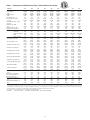
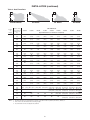
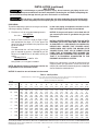
Table 1 - Performance and Dimensional Data - Tubular Blower Unit Heater
Unit Size
100
PERFORMANCE DATA†
Input - BTU/Hr.
100,000
(kW)
(29.3)
Output - BTU/Hr.
83,000
(kW)
(24.3)
Thermal Efficiency - %
83
Free Air Delivery - CFM
1,181
(cu. m/s)
(0.557)
Air Temperature Rise - Deg. F
65
(Deg. C)
(36)
Outlet Velocity - FPM
370
(m/s)
(1.879)
Full Load Amps at 115V
7.3
Maximum Circuit Ampacity
8.6
MOTOR DATA: Motor HP
1/4
Motor kW
0.19
Motor Type ODP† †
SPH
RPM
1,725
Amps @ 115V
5.1
DIMENSIONAL DATA - inches (mm)
"A" Height to Top of Flue
33-3/4
(857)
"B" Jacket Width of Unit
20-3/4
(527)
"C" Width to Centerline Flue
13-3/8
(340)
"D" Depth to Front Hanger
21
(533)
"E" Hanging Distance Width
18-5/8
(473)
"F" Hanging Distance Depth
19
(483)
"G" Discharge Opening Width
18-3/4
(476)
"H" Depth to Centerline Flue
4-3/4
(121)
"L" Discharge Opening Height
24-1/2
(622)
"M" Overall Unit Width
25-1/4
(641)
"P" Overall Unit Depth
49-3/4
(1264)
*Flue Size Diameter - in
5
(mm)
(127)
Blower Size - inches (Qty)
9
Gas Inlet, Natural Gas - in
1/2
Gas Inlet, LP Gas - in
1/2
Approximate Unit Weight - lb
171
(kg)
(78)
Approximate Ship Weight - lb
256
(kg)
(116)
125
150
175
200
250
300
350
400
125,000
(36.6)
103,750
(30.4)
83
1,476
(0.697)
65
(36)
463
(2.351)
9.4
11.2
1/2
0.37
SPH
1,725
7.2
150,000
(44.0)
124,500
(36.5)
83
1,771
(0.836)
65
(36)
555
(2.819)
9.4
11.2
1/2
0.37
SPH
1,725
7.2
175,000
(51.3)
145,250
(42.6)
83
2,067
(0.976)
65
(36)
395.0
(2.006)
14.2
17.1
3/4
0.56
SPH
1,725
11.6
200,000
(58.6)
166,000
(48.6)
83
2,362
(1.115)
65
(36)
451.0
(2.291)
14.2
17.1
3/4
0.56
SPH
1,725
11.6
250,000
(73.3)
207,500
(60.8)
83
2,953
(1.394)
65
(36)
564.0
(2.864)
15.6
18.9
1
0.75
Cap. Start
1,725
13.0
300,000
(87.9)
246,000
(72.1)
82
3,501
(1.652)
65
(36)
422
(2.143)
15.6
18.9
1
0.75
Cap. Start
1,725
13.0
350,000
(102.6)
290,500
(85.1)
83
4,134
(1.951)
65
(36)
498
(2.529)
20.8
25.4
1-1/2
1.11
Cap. Start
1,725
18.2
400,000
(117.2)
332,000
(97.3)
83
4,724
(2.230)
65
(36)
570
(2.895)
20.8
25.4
1-1/2
1.11
Cap. Start
1,725
18.2
33-3/4
(857)
20-3/4
(527)
13-3/8
(340)
21
(533)
18-5/8
(473)
19-1/2
(495)
18-3/4
(476)
4-3/4
(121)
24-1/2
(622)
25-1/4
(641)
49-3/8
(1254)
5
(127)
10
1/2
1/2
175
(79)
261
(118)
33-3/4
(857)
20-3/4
(527)
13-3/8
(340)
21
(533)
18-5/8
(473)
19-1/2
(495)
18-3/4
(476)
4-3/4
(121)
24-1/2
(622)
25-1/4
(641)
49-3/8
(1254)
5
(127)
10
1/2
1/2
202
(92)
289
(131)
33-3/4
(857)
32-3/4
(832)
19-3/8
(492)
21
(533)
30-5/8
(778)
32-3/4
(832)
30-3/4
(781)
4-3/4
(121)
24-1/2
(622)
37-1/4
(946)
56-1/8
(1426)
5
(127)
12
1/2
1/2
245
(111)
381
(173)
33-3/4
(857)
32-3/4
(832)
19-3/8
(492)
21
(533)
30-5/8
(778)
32-3/4
(832)
30-3/4
(781)
4-3/4
(121)
24-1/2
(622)
37-1/4
(946)
56-1/8
(1426)
5
(127)
12
1/2
1/2
264
(120)
400
(181)
33-3/4
(857)
32-3/4
(832)
19-3/8
(492)
21
(533)
30-5/8
(778)
32-3/4
(832)
30-3/4
(781)
4-3/4
(121)
24-1/2
(622)
37-1/4
(946)
56-1/8
(1426)
5
(127)
12
1/2
1/2
289
(131)
425
(193)
34
(864)
50-3/4
(1289)
28-3/8
(721)
21
(533)
48-5/8
(1235)
23-1/2
(597)
48-3/4
(1238)
5-1/8
(130)
24-1/2
(622)
55-1/4
(1403)
53-3/8
(1356)
6
(152)
10 (2)
3/4
3/4
370
(168)
520
(236)
34
(864)
50-3/4
(1289)
28-3/8
(721)
21
(533)
48-5/8
(1235)
32-3/4
(832)
48-3/4
(1238)
5-1/8
(130)
24-1/2
(622)
55-1/4
(1403)
56-1/8
(1426)
6
(152)
12 (2)
3/4
3/4
390
(177)
547
(248)
34
(864)
50-3/4
(1289)
28-3/8
(721)
21
(533)
48-5/8
(1235)
32-3/4
(832)
48-3/4
(1238)
5-1/8
(130)
24-1/2
(622)
55-1/4
(1403)
56-1/8
(1426)
6
(152)
12 (2)
3/4
3/4
429
(195)
595
(270)
† Ratings shown are for unit installations at elevations between 0 and 2,000 ft (0 to 610m). For unit installations in U.S.A. above 2,000 ft. (610m), the unit input must be field derated 4%
for each 1,000 ft. (305m) above sea level; refer to local codes, or in absence of local codes, refer to the latest edition of the National Fuel Gas Code, ANSI Standard Z223.1 (N.F.P.A. No. 54).
For installations in Canada, any reference to deration at altitudes in excess of 2,000 ft. (610m) are to be ignored. At altitudes of 2,000 ft. to 4,500 ft. (610 to 1372m), the unit must be
field derated and be so marked in accordance with the ETL certification. See Table 8A for field deration information.
* Flue collar is factory supplied with unit; to be field installed per included instructions.
† † LEGEND:
SPH = SPLIT PHASE
CAP. START = CAPACITOR START ODP = OPEN DRIP PROOF
4
INSTALLATION
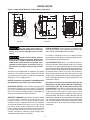
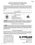
Figure 2 - Dimensional Drawing – Tubular Blower Unit Heater
1 1/8
E
32 1/2
H
M
F
C
D
Flue
B
33
A
L
(Discharge
Opening)
Electrical Control Panel
D8931B
Gas Valve
Rear View
P
Side View
G
(Discharge
Opening)
Front View
D8931B
Do not install unit heaters in
corrosive or flammable atmospheres! Premature
failure of, or severe damage to the unit will
result!
PUBLIC GARAGES: In repair garages, unit heaters must
be located at least 8' (2.4m) above the floor. Refer to the
latest edition of NFPA 88B, Repair Garages.
In Canada, installation must be in accordance to the
latest edition of CSA B149 “Installation Codes for Gas
Burning Appliances and Equipment.”
Avoid locations where extreme
drafts can affect burner operation. Unit heaters
must not be installed in locations where air for
combustion would contain chlorinated, halogenated or acidic vapors. If located in such an
environment, premature failure of the unit will
occur!
AIR DISTRIBUTION: Direct air towards areas of
maximum heat loss. When multiple heaters are involved,
circulation of air around the perimeter is recommended
where heated air flows along exposed walls. Satisfactory
results can also be obtained where multiple heaters are
located toward the center of the area with heated air
directed toward the outside walls. Be careful to avoid
all obstacles and obstructions which could impede the
warm air distribution patterns. Heat throw distances are
presented in Table 2.
Since the unit is equipped with an automatic gas ignition
system, the unit heater must be installed such that the
gas ignition control system is not directly exposed to
water spray, rain or dripping water.
NOTICE: Location of unit heaters is related directly to
the selection of sizes. Basic rules are as follows:
Unit heaters should not be installed to maintain low
temperatures and/or freeze protection of buildings.
A minimum of 50°F (10°C) thermostat setting must
be maintained. If unit heaters are operated to maintain
lower than 50°F (10°C), hot flue gases are cooled
inside the heat exchanger to a point where water
vapor (a flue gas by-product) condenses onto the heat
exchanger walls. The result is a mildly corrosive acid that
prematurely corrodes the aluminized heat exchanger and
can actually drip water down from the unit heater onto
floor surface. Additional unit heaters should be installed
if a minimum 50°F (10°C) thermostat setting cannot be
maintained.
MOUNTING HEIGHT: Unit Heaters equipped with
standard fan guards must be installed at a minimum
of 8' (2.4m) above the floor, measured to the bottom of
the unit. For mounting heights above 8', see Table 2 to
compare unit height to heat throw distance.
AIRCRAFT HANGARS: Unit Heaters must be installed
in aircraft hangars as follows: In aircraft hangars, unit
heaters must be at least 10' (3.0m) above the upper
surface of wings or engine enclosures of the highest
aircraft to be stored in the hangar, and 8' (2.4m) above
the floor in shops, offices and other sections of the
hangar where aircraft are not stored or housed. Refer
to current ANSI/NFPA No. 409, Aircraft Hangars. In
Canada, installation is suitable in aircraft hangars when
acceptable to the enforcing authorities.
5
INSTALLATION (continued)
Table 2 - Heat Throw Data
Standard Heater
30° Nozzle
60° Nozzle
90° Nozzle
UNIT SIZE BTU/Hr
Degree
of
Nozzle
Distance From
Floor to Bottom
of Unit "H" - ft
(m)
100,000
125,000
150,000
None
8
60
65
70
75
80
90
105
110
120
(2.4)
(18.3)
(19.8)
(21.3)
(22.9)
(24.4)
(27.4)
(32.0)
(33.5)
(36.6)
300,000
350,000
400,000
Approximate Distance of Heat Throw - Feet (Meters)
54
56
60
64
68
78
90
95
100
(16.5)
(17.1)
(18.3)
(19.5)
(20.7)
(23.8)
(27.4)
(29.0)
(30.5)
12
44
46
49
57
61
68
80
84
90
(3.7)
(13.4)
(14.0)
(14.9)
(17.4)
(18.6)
(20.7)
(24.4)
(25.6)
(27.4)
NR
NR
NR
NR
20
(6.1)
45
49
52
60
70
74
80
(13.7)
(14.9)
(15.8)
(18.3)
(21.3)
(22.6)
(24.4)
NR
NR
46
54
63
66
70
(14.0)
(16.5)
(19.2)
(20.1)
(21.3)
8
65
70
75
80
85
95
115
120
125
(2.4)
(19.8)
(21.3)
(22.9)
(24.4)
(25.9)
(29.0)
(35.1)
(36.6)
(38.1)
10
57
60
64
68
72
86
99
105
110
(3.0)
(17.4)
(18.3)
(19.5)
(20.7)
(21.9)
(26.2)
(30.2)
(32.0)
(33.5)
12
50
54
57
60
64
77
88
94
100
(3.7)
(15.2)
(16.5)
(17.4)
(18.3)
(19.5)
(23.5)
(26.8)
(28.7)
(30.5)
15
(4.6)
20
(6.1)
NR
NR
45
48
50
53
64
74
79
84
(13.7)
(14.6)
(15.2)
(16.2)
(19.5)
(22.6)
(24.1)
(25.6)
NR
NR
44
47
58
66
71
75
(13.4)
(14.3)
(17.7)
(20.1)
(21.6)
(22.9)
8
75
80
85
90
95
110
125
130
138
(2.4)
(22.9)
(24.4)
(25.9)
(27.4)
(29.0)
(33.5)
(38.1)
(39.6)
(42.1)
10
65
70
75
79
83
95
109
115
120
(3.0)
(19.8)
(21.3)
(22.9)
(24.1)
(25.3)
(29.0)
(33.2)
(35.1)
(36.6)
12
60
64
68
72
76
84
100
103
108
(3.7)
(18.3)
(19.5)
(20.7)
(21.9)
(23.2)
(25.6)
(30.5)
(31.4)
(32.9)
15
50
54
56
61
65
71
85
88
94
(4.6)
(15.2)
(16.5)
(17.1)
(18.6)
(19.8)
(21.6)
(25.9)
(26.8)
(28.7)
20
(6.1)
90°*
250,000
10
15
60°
200,000
(3.0)
(4.6)
30°
175,000
15
(4.6)
20
(6.1)
25
(7.6)
30
(9.1)
NR
30 x 25
49
52
55
59
65
77
81
85
(14.9)
(15.8)
(16.8)
(18.0)
(19.8)
(23.5)
(24.7)
(25.9)
35 x 30
40 x 35
45 x 40
50 x 40
60 x 45
70 x 45
80 x 50
100 x 50
(10.7) (9.1)
(12.2) (10.7)
(13.7) (12.2)
(15.2) (12.2)
(18.3) (13.7)
(21.3) (13.7)
(24.4) (15.2)
(30.5) (15.2)
NR
NR
NR
NR
NR
NR
NR
NR
NR
NR
NR
NR
NR
NR
(9.1)
(7.6)
40 x 35
56 x 40
65 x 40
70 x 45
80 x 45
(12.2) (10.7)
(17.1) (12.2)
(19.8) (12.2)
(21.3) (13.7)
(24.4) (13.7)
50 x 35
60 x 35
65 x 40
75 x 40
(15.2) (10.7)
(18.3) (10.7)
(19.8) (12.2)
(22.9) (12.2)
NR
55 x 35
60 x 35
65 x 40
(16.8) (10.7)
(18.3) (10.7)
(19.8) (12.2)
* It is not recommended to mount a unit with a 90 nozzle under 10 feet.
Notes: 1. All throw data figures are approximations. Allowances should be made for optimum performance, altitude, etc.
2. NR - Units not recommended at these mounting heights.
3. 30°, 60° and 90° nozzles are shipped unassembled.
6
INSTALLATION (continued)
Unit Heaters must be hung level
from side to side and from front to back, see Figure
3A and 3B. Failure to do so will result in poor
performance and/or premature failure of the unit.
AIR FOR COMBUSTION: The unit heater shall be
installed in a location in which the facilities for
ventilation permit satisfactory combustion of gas,
proper venting, and the maintenance of ambient
temperature at safe limits under normal conditions of
use. The unit heater shall be located in such a manner
as not to interfere with proper circulation of air within the
confined space. When buildings are so tight that normal
infiltration does not meet air requirements, outside air
shall be introduced per Sections 1.3.4.2 and 1.3.4.3 of
ANSI Z223.1 for combustion requirements. A permanent
opening or openings having a total free area of not less
than one square inch per 5,000 BTU/Hr (1.5 kW) of total
input rating of all appliances within the space shall be
provided.
Ensure that all hardware used in
the suspension of each unit heater is more than
adequate for the job. Failure to do so may result
in extensive property damage, severe personal
injury, or death!
Refer to Figures 3A and 3B for suspension of units.
Figure 3A - Heater Mounting*
NOTICE: Unit Heater sizing should be based on heat
loss calculations where the unit heater output equals
or exceeds heat loss.
CLEARANCES: Each Gas Unit Heater shall be
located with respect to building construction and other
equipment so as to permit access to the Unit Heater.
Clearance between vertical walls and the vertical sides
of the Unit Heater shall be no less than 6" (152mm).
To ensure access to the control box, a minimum of 18"
(457mm) is required for the control box side. A minimum
clearance of 6" (152mm) must be maintained between
the top of the Unit Heater and the ceiling. The bottom of
the Unit Heater must be no less than 12" (305mm) from
any combustible. The distance between rear of unit and
vertical wall should be no less than 18" to maintain inlet
air flow. The distance between the flue collector and any
combustible must be no less than 6" (152mm). Also see
AIR FOR COMBUSTION and VENTING sections.
D2788A
*All hanging hardware and wood is not included with the unit (To
be field supplied).
Figure 3B - Heater Suspension
NOTICE: Increasing the clearance distances may
be necessary if there is a possibility of distortion or
discoloration of adjacent materials.
Make certain that the lifting
methods used to lift the heater and the method
of suspension used in the field installation of the
heater are capable of uniformly supporting the
weight of the heater at all times. Failure to heed
this warning may result in property damage or
personal injury!
Make sure that the structure
to which the unit heater is to be mounted is
capable of safely supporting its weight. Under
no circumstances must the gas lines, the venting
system or the electrical conduit be used to
support the heater; or should any other objects
(i.e. ladder, person) lean against the heater gas
lines, venting system or the electrical conduit for
support. Failure to heed these warnings may result
in property damage, personal injury, or death.
D4804
7
INSTALLATION (continued)
GAS PIPING
To avoid damage or possible personal injury, do not connect gas piping to this unit
until a supply line pressure/leak test has been completed. Connecting the unit before completing the
pressure/leak test may damage the unit gas valve and result in a fire hazard.
Do not rely on a shut-off valve to isolate the unit while conducting gas pressure/leak tests.
These valves may not be completely shut off, exposing the gas valve to excessive pressure and damage.
PIPE SIZING
To provide adequate gas pressure to the gas unit heater,
size the gas piping as follows:
by the same piping arrangement, the total cu. ft./hr.
input and length of pipe must be considered.
1. Find the cu. ft./hr. by using the following formula:
Input BTU/Hr.
Cu. ft./hr. =
1000
NOTICE: If the gas unit heater is to be fired with LP
gas, consult your local LP gas dealer for pipe size
information.
2. Refer to Table 3. Match “Length of Pipe in Feet”
with appropriate “Gas Input - Cu. Ft./Hr.” figure. This
figure can then be matched to the pipe size at the
top of the column.
Example:
It is determined that a 67 foot (20.4m) run of gas
pipe is required to connect a 200 MBTU gas unit
heater to a 1,000 BTU/cu ft. (0.29kW) natural gas
supply.
200,000 BTU/Hr = 200 Cu. ft./hr.
1,000 BTU/cu. ft.
Using Table 3, a 1 inch pipe is needed.
NOTICE: HEATER INSTALLATION FOR USE WITH
PROPANE (BOTTLED) GAS MUST BE MADE BY
A QUALIFIED L.P. GAS DEALER OR INSTALLER.
HE/SHE WILL INSURE THAT PROPER JOINT
COMPOUNDS ARE USED FOR MAKING PIPE
CONNECTIONS; THAT AIR IS PURGED FROM
LINES; THAT A THOROUGH TEST IS MADE FOR
LEAKS BEFORE OPERATING THE HEATER; AND
THAT IT IS PROPERLY CONNECTED TO THE
PROPANE GAS SUPPLY SYSTEM.
Before any connection is made to the existing line
supplying other gas appliances, contact the local gas
company to make sure that the existing line is of adequate
size to handle the combined load.
NOTE: See General Safety Information section for
English/Metric unit conversion factors.
NOTICE: If more than one unit heater is to be served
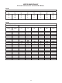
Table 3 - Gas Pipe Size
Maximum Capacity of Pipe in Cubic Feet of Gas per Hour (Cubic Meters per Hour) for Gas Pressures of 0.5 psig (3.5 kPa) or Less,
and a Pressure Drop of 0.5 Inch Water Column (124.4 Pa)
(Based on a 0.60 Specific Gravity Gas)
Nominal
Iron
Internal
Pipe Size
Dia.
in.
1/2
in.
0.622
3/4
0.824
1
1.049
1 1/4
1.380
1 1/2
1.610
2
2.067
2 1/2
2.469
3
3.068
4
4.026
Length of Pipe, Feet (meters)
10
(3.0)
175
(4.96)
360
(10.2)
680
(19.3)
1400
(39.6)
2100
(59.5)
3950
(112)
6300
(178)
11000
(311)
23000
(651)
20
(6.1)
120
(3.40)
250
(7.08)
465
(13.2)
950
(26.9)
1460
(41.3)
2750
(77.9)
4350
(123)
7700
(218)
15800
(447)
30
(9.1)
97
(2.75)
200
(5.66)
375
(10.6)
770
(21.8)
1180
(33.4)
2200
(62.3)
3520
(99.7)
6250
(177)
12800
(362)
40
(12.2)
82
(2.32)
170
(4.81)
320
(9.06)
660
(18.7)
990
(28.0)
1900
(53.8)
3000
(85.0)
5300
(150)
10900
(309)
50
(15.2)
73
(2.07)
151
(4.28)
285
(8.07)
580
(16.4)
900
(25.5)
1680
(47.6)
2650
(75.0)
4750
(135)
9700
(275)
60
(18.3)
66
(1.87)
138
(3.91)
260
(7.36)
530
(15.0)
810
(22.9)
1520
(43.0)
2400
(68.0)
4300
(122)
8800
(249)
70
(21.3)
61
(1.73)
125
(3.54)
240
(6.80)
490
(13.9)
750
(21.2)
1400
(39.6)
2250
(63.7)
3900
(110)
8100
(229)
80
(24.4)
57
(1.61)
118
(3.34)
220
(6.23)
460
(13.0)
690
(19.5)
1300
(36.8)
2050
(58.0)
3700
(105)
7500
(212)
90
(27.4)
53
(1.50)
110
(3.11)
205
(5.80)
430
(12.2)
650
(18.4)
1220
(34.5)
1950
(55.2)
3450
(97.7)
7200
(204)
100
(30.5)
50
(1.42)
103
(2.92)
195
(5.52)
400
(11.3)
620
(17.6)
1150
(32.6)
1850
(52.4)
3250
(92.0)
6700
(190)
125
(38.1)
44
(1.25)
93
(2.63)
175
(4.96)
360
(10.2)
550
(15.6)
1020
(28.9)
1650
(46.7)
2950
(83.5)
6000
(170)
150
(45.7)
40
(1.13)
84
(2.38)
160
(4.53)
325
(9.20)
500
(14.2)
950
(26.9)
1500
(42.5)
2650
(75.0)
5500
(156)
175
(53.3)
37
(1.05)
77
(2.18)
145
(4.11)
300
(8.50)
460
(13.0)
850
(24.1)
1370
(38.8)
2450
(69.4)
5000
(142)
200
(61.0)
35
(0.99)
72
(2.04)
135
(3.82)
280
(7.93)
430
(12.2)
800
(22.7)
1280
(36.2)
2280
(64.6)
4600
(130)
1. Determine the required Cu. Ft./Hr. by dividing the input by 1000. For SI/Metric measurements: Convert BTU/Hr. to kilowatts. Multiply the units
inputs (kW) by 0.0965 to determine Cu. Meters./Hr. 2. FOR NATURAL GAS: Select pipe size directly from the table. 3. FOR PROPANE GAS:
Multiply the Cu. Ft./Hr. value by 0.633; then, use the table. 4. Refer to the metric conversion factors listed in the General Safety section for SI Unit
measurement conversions.
8
INSTALLATION (continued)
PIPE INSTALLATION
Figure 4 - Pipe Installation, Standard Controls
1. Install the gas piping in accordance with applicable
local codes.
2. Check gas supply pressure. Each unit heater must
be connected to a manifold pressure and a gas
supply capable of supplying its full rated capacity as
specified in Table 4. A field LP tank regulator must
be used to limit the supply pressure to a maximum
of 14" W.C. (3.5 kPa). All piping should be sized in
accordance with the latest edition of ANSI Standard
Z223.1 (NFPA54), National Fuel Gas Code; in
Canada, according to CSA B149. See Tables 1
& 3 for correct gas piping size. If gas pressure is
excessive on natural gas applications, install a
pressure regulating valve in the line upstream from
the main shutoff valve.
3. Adequately support the piping to prevent strain on
the gas manifold and controls.
4. To prevent the mixing of moisture with gas, run the
take-off piping from the top, or side, of the main.
5. Standard Unit Heaters, optional two-stage units are
supplied with a combination valve which includes:
a. Manual "A" valve
b. Manual "B" valve
c. Solenoid valve
d. Pressure regulator
Pipe directly into the combination valve (see Figure
4).
6. Gas valve has a pressure test post requiring a
3/32" hex head wrench to read gas supply and
manifold pressures. Open 1/4 turn counterclockwise
to read, turn clockwise to close and reseat. A 5/16"
ID hose fits the pressure post.
7. Provide a drip leg in the gas piping near the gas
unit heater. A ground joint union and a manual gas
shutoff valve should be installed ahead of the unit
heater controls to permit servicing. The manual
shutoff valve must be located external to the jacket
(See Figure 4).
8. Make cer tain that all connections have been
adequately doped and tightened.
D3631C
D3631C
Never use an open flame to detect
gas leaks. Explosive conditions may exist which
may result in personal injury or death!
The appliance and its individual shutoff valve must be
disconnected from the gas supply piping system during
any pressure testing of that system in excess of 1/2 psig
(3.5 kPa).
The appliance must be isolated from the gas supply
piping system by closing its individual manual shutoff
valve during any pressure testing of the gas supply
piping system at test pressures equal to or less than
1/2 psig (3.5 kPa).
Table 4 - Gas Piping Requirements
SINGLE STAGE GAS PIPING REQUIREMENTS*
Do not over tighten the inlet gas
piping into the valve. This may cause stresses that
will crack the valve!
GasType
Natural Gas
Propane (LP) Gas
Manifold
Pressure
3.5 in. W.C.
(0.9 kPa)
10.0 in. W.C.
(2.5 kPa)
14.0 in. W.C. Max.
(3.5 kPa)
14.0 in. W.C. Max.
(3.5 kPa)
5.0 in. W.C. Min.
(1.2 kPa)
11.0 in W.C. Min.
(2.7 kPa)
Supply Inlet
Pressure
*For single stage application only at normal altitudes.
NOTICE: Use pipe joint sealant resistant to the
action of liquefied petroleum gases regardless of
gas conducted.
Check all pipe joints for leakage
using a soap solution or other approved method.
Never use an open flame or severe personal
injury or death may occur!
9
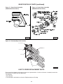
BLOWER SET UP AND ADJUSTMENT
BLOWER SET UP
The drive ratio of the motor and blower sheaves has
been preset at the factory for a temperature rise of 65°F
at .2" W.C. If the unit is to be operated under different
static air flow or pressure requirements, the drive ratio
must be altered by means of the adjustable sheave on
the blower motor.
1. Ensure that all packing material, support blocks, etc.
have been removed from the unit.
2. Adjust the blower drive belt tension by means of the
two tension bolts on the blower motor base. When
proper tension has been achieved, the mid-point
deflection of the belt will be 3/4" when subjected to a
5 lb. force.
3. Recheck all electrical connections.
4. When power is applied, ensure that the motor and
blower are rotating in a counter clockwise direction
when viewed from the drive side.
5. Measure the current draw of the motor.
BLOWER DRIVE ADJUSTMENT
Never attempt to adjust the drive
belt without first disconnecting all electrical
power to the unit or severe personal injury may
result!
1. Remove the belt guard and loosen the belt tension
bolts on the blower motor base.
2. Loosen the set screw on the adjustable half of the
motor sheave. To increase the blower speed, turn
the adjustable half of the sheave clockwise, counter
clockwise to slow the blower. Retighten the set
screw.
3. Realign the blower and motor sheaves if necessary.
4. Adjust the belt tension as specified in the BLOWER
SET UP section under step 2.
5. Replace the belt guard.
Never operate the unit without
the belt guard in place or severe personal injury
may result!
The "at speed" current draw of the
motor must never exceed that specified on the
motor rating plate or severe damage to the motor
will result!
6. Check that the air flow of the unit, the rpm
and current draw of the blower motor and the
temperature rise are within the limits specified in
Table 1, the blower motor rating plate and the rating
plate on the unit, respectively (also see Motor Data
on page 11).
Figure 5 - Motor & Blower Assembly *
* PART DESCRIPTION
A. Blower Housing and Wheel
C. Blower Shaft
D. Bearings
E. Drive Pulley
F. Driven Pulley
G. V-Belt
H. Blower Motor
I. Blower Housing Support (LH)
H. Blower Housing Support (RH)
D9000
Never operate the unit beyond
the specified limits or severe damage to, and or
premature failure of, the unit will result!
* NOTICE: THE BLOWER ASSEMBLY FOR THE 100/250 UNITS
CONSISTS OF 1 WHEEL, 1 HOUSING, 1 SHAFT AND 2 BEARINGS.
FOR 300/400 UNITS THE BLOWER ASSEMBLY CONSISTS OF 2
WHEELS, 2 HOUSINGS, 1 SHAFT AND 3 BEARINGS.
10
MOTOR AND PULLEY
All motor data based on standard ODP Motors.
Table 5
Motor Full Load Amps*
HP
1/4
1/2
3/4
1
1-1/2
2
115-1
5.1
7.2
11.6
13.0
18.2
21.0
208-1
2.2
3.7
5.2
6.6
9.1
11.3
VOLTAGE - PHASE
230-1
208-3
2.3
1.7
3.8
2.3
5.0
3.0
6.5
3.4
9.1
5.1
10.5
6.2
* Average value, all speeds and frequencies.
230-3
1.3
2.2
3.4
3.4
5.2
6.0
460-3
0.7
1.1
1.7
1.7
2.6
3.0
575-3
N/A
0.8
1.1
1.3
1.7
N/A
Table 6
Pulley Table 1725 RPM Motors (1/3 to 2 H.P.)
BLOWER PULLEYS
MOTOR PULLEYS
IVL44
IVL34
2.8-3.8
1.9-2.9
Turns Open
5
4-1/2
4
3-1/2
3
2-1/2
2
1-1/2
1
1/2
5
0
4-1/2
4
3-1/2
3
2-1/2
2
1-1/2
1
1/2
0
AK51
4.7
AK56
5.2
AL64
6.0
AL74
7.0
AL84
8.0
AL104
10.0
697
734
771
807
844
880
918
954
991
1027
1064
1101
1137
1174
1211
1247
1284
1321
1357
1394
630
663
697
730
763
796
829
863
896
928
962
995
1028
1061
1094
1127
1161
1194
1227
1260
546
575
603
633
661
690
719
748
776
805
834
863
891
920
949
978
1006
1035
1064
1093
468
493
517
542
567
591
616
641
665
690
715
739
764
789
813
838
863
887
912
936
410
431
453
474
496
517
539
560
582
604
625
647
668
690
712
733
755
776
798
819
327
345
362
380
397
414
431
448
466
483
500
518
535
552
569
587
604
621
638
656
11
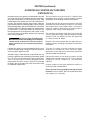
ELECTRICAL CONNECTIONS
Figure 6a Low-voltage
Thermostat Wiring
Single Stage
HAZARDOUS VOLTAGE!
DISCONNECT ALL ELECTRIC
POWER INCLUDING REMOTE
DISCONNECTS BEFORE
SERVICING. Failure to
disconnect power before
servicing can cause severe
personal injury or death.
D4788
Figure 6b Low-voltage
Thermostat Wiring
Two Stage
Standard units are shipped for use on 115 volt, 60 hertz,
single phase electric power. The motor name-plate and
electrical rating of the transformer should be checked
before energizing the unit heater electrical system. All
external wiring must conform to the latest edition of
ANSI/NFPA No. 70, United States National Electrical
Code, and applicable local codes; in Canada, to the
Canadian Electrical Code, Part 1, CSA Standard C22.1.
Figure 6c Low-voltage
T834H or T834N
(or equivalent)
Thermostat Wiring
Single Stage
D8541
D8922C
NOTICE: The start-up fan delay should not exceed
30 seconds from a cold start.
Do not use any tools (i.e. screwdriver,
pliers, etc.) across terminals to check for power. Use
a voltmeter.
IMPORTANT: For all wiring connections, refer to the
wiring diagram shipped with your unit (either affixed
to the side jacket or enclosed in the installation
instructions envelope). Should any original wire
supplied with the heater have to be replaced, it
must be replaced with wiring material having a
temperature rating of at least 105°C.
It is recommended that the electrical power supply to
each unit heater be provided by a separate, fused, and
permanently live electrical circuit. A disconnect switch of
suitable electrical rating should be located as close to
the gas valve and controls as possible. Each unit heater
must be electrically grounded in accordance with the
latest edition of the United States National Electrical
Code, ANSI/NFPA No. 70, or CSA Standard C22.1. Refer
to Figures 6a, 6b, 6c, 6d, 6e, 6f and 6g.
Should any high limit wires have to be replaced,
they must be replaced with wiring material having a
temperature rating of 200°C minimum.
THERMOSTAT WIRING AND LOCATION:
NOTICE: The thermostat must be mounted on a
vertical, vibration-free surface, free from air currents,
and in accordance with the furnished instructions.
Mount the thermostat approximately 5' (1.5m) above
the floor, in an area where it will be exposed to a free
circulation of average temperature air. Always refer to
the thermostat instructions, as well as our unit wiring
diagram, and wire accordingly. Avoid mounting the
thermostat in the following locations:
1. Cold Areas - Outside walls or areas where drafts
may affect the operation of the control.
2. Hot Areas - Areas where the sun's rays, radiation,
or warm air currents may affect the operation of
the control.
3. Dead Areas - Areas where the air cannot circulate
freely, such as behind doors or in corners.
12
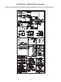
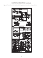
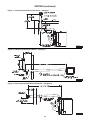
ELECTRICAL CONNECTIONS (continued)
Figure 6d - Tubular Blower Units 100-150 with Single Stage Ignition, Natural Gas and Propane (LP) Gas
13
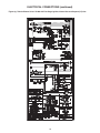
ELECTRICAL CONNECTIONS (continued)
Figure 6e - Tubular Blower Units 100-150 with Two Stage Ignition, Natural Gas and Propane (LP) Gas
14
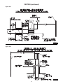
ELECTRICAL CONNECTIONS (continued)
Figure 6f - Tubular Blower Units 175-400 with Single Stage Ignition, Natural Gas and Propane (LP) Gas
15
ELECTRICAL CONNECTIONS (continued)
Figure 6g - Tubular Blower Units 175-400 with Two Stage Ignition, Natural Gas and Propane (LP) Gas
16
VENTING
ANSI now organizes vented
appliances into four categories.
Venting Categories
Non
Condensing
Condensing
I
II
III
IV
Negative
Vent
Pressure
Positive
Vent
Pressure
Category I
Includes non-condensing
appliances with negative vent
pressure, like the traditional
atmospheric unit heater.
Category II
Groups condensing appliances
with negative vent pressure.
Category IV
Covers condensing appliances with
positive vent pressure.
NOTICE: Category II and IV do
not apply to equipment specified
within this manual.
Category III
Appliances are non-condensing
and operate with a positive vent
pressure.
All unit heaters must be vented! All Venting installations shall be in accordance with the latest edition of Part 7,
Venting of Equipment of the National Fuel Gas Code, ANSI Z223.1 (NFPA54), or applicable provisions of local
building codes. See below for Canadian installations. Refer to Figures 7, 8, 9, 10A, 10B, 11A and 11B.
CARBON MONOXIDE! Your venting system must not be blocked by any snow, snow
drifts, or any foreign matter. Inspect your venting system to ensure adequate ventilation exists at all
times! Failure to heed these warnings could result in Carbon Monoxide Poisoning (symptoms include
grogginess, lethargy, inappropriate tiredness, or flu-like symptoms).
Do not damper or add heat recovery devices to the flue piping. Failure to open such a damper prior to operating
gas unit will result in the spillage of flue gas into the occupied space.
ADDITIONAL REQUIREMENT FOR
CANADIAN INSTALLATIONS
Table 7
Vent Systems
Termination Clearance Requirements
REFER TO SPECIFICATION TABLE AND INSTALLATION MANUAL
FOR PROPER USAGE.
* The following instructions apply to Canadian installations in addition
to installation and operating instructions.
1. Installation must conform with local building codes, or in the absence
of local codes, with current CSA B149.1, Installation Codes for
Natural Gas Burning Appliances and Equipment, or CSA B149.2,
Installation Codes for Propane Gas Burning Appliances and
Equipment.
2. Any reference to U. S. standards or codes in these instructions are to
be ignored, and the applicable Canadian standards or codes applied.
Minimum Clearance
for Termination Locations
Structure/Object
USA
CANADA
Door, window, or gravity vent
inlet; combustion air inlet for
other appliances
9 inch for 10,000 to
50,000 BTU/Hr
input; 12 inch for
input exceeding
50,000 BTU/Hr.
9 inch (230mm) for
10,000 to 50,000
BTU/Hr input;
12 inch (305mm)
for input exceeding
50,000 BTU/Hr.
Forced air inlet within 10 feet
3 feet above
6 feet (1.8m)
Adjoining Building or parapet
6 feet
6 feet (1.8m)
Adjacent public walkways
7 feet above
grade
7 feet (2.1m) above
grade
Electric, gas meters
& regulators
4 feet horizontal
3 feet (0.9m)
horizontally from
meter/regulator
asembly. 6 feet
(1.8m), any
direction, from
a gas service
regulator vent outlet
Above grade level*
1 foot*
1 foot (0.3m)*
*Minimum above maximum snow depth, or per local code, whichever is
greater.
17
VERTICALLY VENTED UNIT HEATERS (CATEGORY I)
Observe the following precautions when venting the unit:
1. Use flue pipe of the same size as the flue connections on
the gas unit heater (See Table #1). All heaters should be
vented with double wall or single wall vent, a factory built
chimney, or a lined brick and mortar chimney that has
been constructed in accordance with the National Building
Code. Type B vent should only be used for vertical rise
portions of a Category I vent pipe system. Type B vent
pipe should not be used for horizontal runs of vent pipe.
4. Use as few elbows as possible.
2. Provide as long a vertical run of flue pipe at the gas
unit heater as possible. A minimum of 5' (1.5m) of
vertical flue is required. The top of the vent pipe
should extend at least 2' (0.61m) above the highest
point on the roof. Install a weather cap over the
vent opening. Consideration should be made for
anticipated snow depth.
7. When this cannot be avoided, insulate the pipe to
prevent condensation of moisture on the walls of the
pipe.
3. Slope horizontal runs upward from the gas unit
heater at least 1/4" per foot (21mm/m) minimum.
Horizontal runs should not exceed 75% of the
vertical height of the vent pipe, or chimney, above
the flue pipe connection, up to a maximum length of
10' (3m). Horizontal portions of the venting system
shall be supported at minimum intervals of 4' (1.2m).
In Canada, support at minimum intervals of 3' (1m).
9. Avoid installing units in areas under negative pressure
due to large exhaust fans or air conditioning. When
required, a flue vent fan should be installed in
accordance with the instructions included with the fan.
5. Seal all vent pipe joints and seams to prevent
leakage. Use General Electric RTV-108, Dow
Corning RTV-732, or equivalent silicone sealant
with a temperature rating of 500 degrees F, or 3M
#425 aluminum foil tape (or equivalent).
6. Avoid running vent pipe through unheated spaces.
8. Do not damper the flue piping. Failure to open such a
damper prior to operating the gas unit heater will result
in the spillage of flue gas into the occupied space.
10. Vent connectors serving Category I and Category
II heaters shall not be connected into any portion of
mechanical draft systems operating under positive
pressure.
HORIZONTALLY VENTED UNIT HEATERS (CATEGORY I)
NOTICE: Horizontal Venting is only considered Category I for commercial applications if the unit is noncondensing and there is negative vent pressure in the flue pipe. If flue pipe is under positive pressure, see
Horizontally Vented Unit Heaters (Category III) section.
5. The vent terminal must be at least 12 inches (305mm)
from the exterior of the wall that it passes through to
prevent degradation of the building material by flue gases.
Observe the following precautions when venting the unit:
1. Use flue pipe of the same size as the flue connections
on the gas unit heater (See Table 1). All heaters should
be vented with appropriately sealed double wall or single
wall vent.Venting systems using Type B vent must comply
with National Fuel Gas Code, ANSI Z223.1 (NFPA54)
6. Seal all vent pipe joints and seams to prevent leakage.
Use General Electric RTV-108, Dow-Corning RTV-732,
or equivalent silicone sealant with a temperature rating
of 500 deg. F, or 3M # 425 aluminum foil tape (or
equivalent). The vent system must be installed to prevent
collection of condensate. Pitch horizontal pipes downward
¼ inch per foot (21mm per meter) toward the outlet for
condensate drainage. Install a tee with a condensate
drain at the low point of the pipe (see Figure 8). As an
alternate, a 3/8 inch diameter hole may be drilled at the
low point of the pipe for condensate drainage.
2. Each unit must have an individual vent pipe and vent
terminal. Unit must not be connected to other vent
systems or to a chimney.
3. The system must have a minimum vertical rise to ensure
that the vent pipe is under negative pressure. Install a
weather cap over the vent opening. A Breidert Type L,
Fields Starkap or equivalent vent cap must be supplied
by the customer for each power vented unit. Consideration
should be made for anticipated snow depth.
7. Horizontal portions of the venting system shall be
supported at minimum intervals of 4 feet (1.2m) to
prevent sagging (in Canada, support at 3 foot (1m)
minimum intervals).
4. Through the wall venting for these appliances shall not
terminate over public walkways, or over an area where
the condensate or vapor could create a nuisance,
hazard, or could be detrimental to the operation of
regulators, relief valves, or other equipment.
8. Avoid running vent pipe through unheated spaces. When
this cannot be avoided, insulate the pipe to prevent
condensation of moisture on the walls of the pipe.
18
VENTING (continued)
HORIZONTALLY VENTED UNIT HEATERS
(CATEGORY III)
Horizontal venting arrangements are designed to be used
with single wall vent pipe. Horizontal venting arrangements
must terminate external to the building using UL 1738
Listed single wall or double wall vent. For installations in
Canada, use corrosion resistant and gas-tight, listed vent
pipe conforming with local building codes, or in the absence
of local building codes, with current CSA-B149.1, Installation
Codes for Natural Gas Burning Appliances and Equipment
or CSA-B149.2, Installation Codes for Propane Gas
Burning Appliances and Equipment. See Figures 9, 10A
and 11A for special installation requirements regarding
these venting conditions.
The vent terminal must be at least 12" (305mm) from
the exterior of the wall that it passes through to prevent
degradation of the building material by flue gases.
Through the wall vent for these appliances shall NOT
terminate over public walkways, or over an area where
the condensate or vapor could create a nuisance or
hazard or could be detrimental to the operation of
regulators, relief valves, or other equipment.
The vent pipe equivalent length must not exceed 50'
(15.2m). Equivalent length is the total length of straight
sections PLUS 10' (3.05m) for each 90° elbow and
4' (1.22m) for each 45° elbow.
Do not use Type B (double wall)
vent internally within the building on horizontally
vented power vented units! This can result in
death, serious injury or substantial property
damage.
Maintain clearance between the vent pipe and combustible materials according to vent pipe manufacturers
instructions
If double wall venting is used, components which are UL
Listed and approved for Category III positive pressure
venting systems MUST be used.
The vent air system must be installed to prevent
collection of condensate. Pitch horizontal pipes
downward 1/4" per foot (21mm per meter) toward the
outlet for condensate drainage.
A Breidert Type L, Fields Starkap, or equivalent vent cap
must be supplied by the customer for each power vented
unit. The vent pipe diameter MUST be as specified in
Table 1. All unit sizes are factory equipped with the
required flue size collar; attach in place (if not mounted
to outlet); refer to included vent collar instruction sheet
for additional requirements.
Horizontal portions of the venting systems shall be
supported at maximum intervals of 4' (1.2m) to prevent
sagging (in Canada, suppor t at 3' (1m) maximum
intervals).
Insulate single wall vent pipe exposed to cold air or
running through unheated areas.
Each unit must have an individual vent pipe and vent
terminal! Each unit MUST NOT be connected to other
vent systems or to a chimney.
19
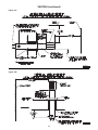
VENTING (continued)
Figure 7 - Vertically Vented Tubular Unit Heater – Category I
D8929
Figure 8 - Horizontally Vented Unit Heater – Category I
D6838C
Figure 9 - Horizontally Vented Tubular Unit Heater – Category III
D8930
20
VENTING (continued)
Figure 10A
D3620F
Figure 10B
D3619C
21
VENTING (continued)
Figure 11A
D3661F
Figure 11B
D3662D
22
OPERATION
POWER VENTED BLOWER UNITS
DIRECT SPARK IGNITION
EXPLANATION OF CONTROLS:
1. The unit heater is equipped with a power vent system
that consists of a power venter motor and blower,
pressure switch, and sealed flue collector in place of
the conventional draft diverter.
2. The power venter motor is energized by the room
thermostat through the integrated control board when
a demand for heat is sensed. The pressure switch
measures the flow through the vent system and
energizes the direct spark ignition system beginning
the pre-purge timing when the flow is correct.
7. The wall thermostat, supplied optionally, is a
temperature sensitive switch that operates the vent
and ignition system to control the temperature of
the space being heated. The thermostat must be
mounted on a vertical, vibration-free surface free
from air currents and in accordance with the furnished
instructions (also refer to Electrical Connections).
START-UP (Also refer to lighting instruction plate
equipped on the unit)
1. Open the manual gas valve in the gas supply line to
the unit heater. Loosen the union in the gas line to
purge it of air. Tighten the union and check for leaks.
The pressure switch MUST NOT be
bypassed. The unit MUST NOT be fired unless the
power venter is operating. An unsafe condition
could result.
Never use an open flame to detect gas leaks. Explosive conditions may exist
which could result in personal injury or death.
3. The direct ignition system consists of an ignition
control module and a gas valve. When the prepurge period ends, the spark ignition system is
energized, and the gas valve opens to supply gas
to the burners. When the thermostat is satisfied, the
vent system is de-energized and the valve closes to
stop the flow of gas to the unit. (See Figure 12.)
4. The limit switch interrupts the flow of electric current
to the control board, interrupting the flow of gas to the
gas valve if the unit heater becomes overheated.
5. Once the thermostat is satisfied, or the limit switch
interrupts the flow of electric current to the control
board, the unit will begin a post-purge period. When
the post-purge period ends, the power venter motor
is de-energized.
6. The fan operation is delayed 30 seconds once the
thermostat is closed, and continues operation for 30
seconds after the thermostat opens.
2. Open the manual valve on the unit heater.
3. Turn ON the electrical power.
4. The unit should be under the control of the thermostat.
Turn the thermostat to the highest point and determine
that the power venter motor starts and the burners
ignite. Turn the thermostat to the lowest point and
determine that the power venter motor shuts off and
the burners are extinguished.
5. Turn the thermostat to the desired position.
6. See Gas Input Rate and Adjustments sections.
SHUT DOWN
1. Turn the valve selector lever to the “OFF” position.
2. Turn off the electricity.
3. To relight, follow “start-up” instructions.
See Figures 12-19 for parts/identification.
NOTICE: The start-up fan delay must not exceed 30
seconds from a cold start.
Figure 12 - Direct Spark Ignition
System, Bottom View
D6923B
23
OPERATION
PRIMARY AIR SHUTTER ADJUSTMENT
Primary air adjustment is made at the factory. No field adjustments are necessary.
GAS INPUT RATE
Check the gas input rate as follows (Refer to General
Safety Information section for metric conversions).
2. PROPANE GAS: An exact manifold pressure of
10.0" W.C. (2.5 kPa) must be maintained for proper
operation of the unit heater. If the unit is equipped
with a pressure regulator on the combination gas
valve, follow steps "a" through "d" above. If the unit
is not so equipped, the propane gas supply system
pressure must be regulated to attain this manifold
operating pressure.
3. The adjusted manifold pressure should not vary
more than 10% from pressure specified in Table 8.
Never overfire the unit heater, as this
may cause unsatisfactory operation, or shorten the
life of the heater.
1. Turn off all gas appliances that use gas through the
same meter as the unit heater.
2. Turn the gas on to the unit heater.
3. Clock the time in seconds required to burn 1 cubic
foot of gas by checking the gas meter.
4. Insert the time required to burn one cubic foot of
gas into the following formula and compute the input
rate.
3600 (Sec. per Hr.) X BTU/Cu. Ft.
Time (Sec.)
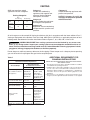
Table 8 - Main Burner Orifice Schedule*
TYPE OF GAS
INPUT HEATING VALUE
IN
1,000
MANIFOLD
BTU
PRESSURE
= Input Rate
100
For example:
Assume the BTU content of one cubic foot of gas is
1000, and that it takes 18 seconds to burn one cubic
foot of gas.
3600 x 1000
= 200,000
18
125
150
175
200
NOTICE: If the computation exceeds, or is less than
95% of the gas BTU/hr. input rating (see Table 1),
adjust the gas pressure.
250
300
Adjust the gas pressure as follows:
350
1. NATURAL GAS: Best results are obtained when
the unit heater is operating at its full rated input
with the manifold pressure of 3.5" W.C. (0.9 kPa).
Adjustment of the pressure regulator is not normally
necessary since it is preset at the factory. However,
field adjustment may be made as follows:
a. Attach manometer at the pressure tap plug
adjacent to the control outlet.
b. Remove the regulator adjustment screw cap,
located on the combination gas valve.
c. With a small screwdriver, rotate the adjustment
screw counterclockwise to decrease pressure, or
clockwise to increase pressure.
d. Replace regulator adjustment screw cap.
24
400
NATURAL
PROPANE
1050 BTU/Ft3
(39.1 MJ/m3)
2500 BTU/Ft3
(93.1 MJ/m3)
3.5" W.C.
10" W.C.
(0.87kPA)
(2.49kPA)
FT3/HR
93
40
ORIFICE DRILL
42
53
FT3/HR
116
50
ORIFICE DRILL
42
53
FT3/HR
140
60
ORIFICE DRILL
42
53
FT3/HR
163
70
ORIFICE DRILL
42
53
FT3/HR
186
80
ORIFICE DRILL
42
53
FT3/HR
233
100
ORIFICE DRILL
42
53
FT3/HR
280
120
ORIFICE DRILL
42
53
FT3/HR
326
140
ORIFICE DRILL
42
53
FT3/HR
372
160
ORIFICE DRILL
42
53
NO. OF
BURNER
ORIFICES
4
5
6
7
8
9
10
11
12
*This schedule is for units at operating at normal altitudes of 2000 ft. (610m)
or less.
When installed in Canada, any references to deration at altitudes in excess
of 2000 ft. (610m) are to be ignored. At altitudes of 2000 to 4500 ft. (610
to 1372m), the unit heaters must be field derated and be so marked in
accordance with ETL certification. See Table 8A for field deration information.
OPERATION (continued)
TUBULAR UNIT HEATER
HIGH ALTITUDE DERATION
This Tubular Unit Heater has been manufactured utilizing
standard burner orifices and a normal manifold pressure
setting as per the specifications shown on your unit rating
plate.
are made in the field, attach label #J17-06459 to the unit,
and record adjusted manifold pressure, altitude of the
unit installation and the technician’s name and date on
the label using a permanent marker.
All unit deration must be done through field adjustments
by a qualified technician. Once the proper adjustments
Refer to Installation Instruction section on AdjustmentsGas Input Rate for adjusting the manifold pressure.
Table 8A
High Altitude Deration - United States
Manifold Pressure
Altitude
Natural Gas2
BTU Output1
Liquid Propane3
Feet
Meters
Inches W.C.
Pa
Inches W.C.
Pa
Percentage
0-2,000
0-610
3.5
872
10
2,491
100%
2,001-3,000
611-915
3.2
797
9.2
2,292
96%
3,001-4,000
916-1,220
2.9
722
8.4
2,092
92%
4,001-5,000
1,221-1,525
2.7
673
7.7
1,918
88%
5,001-6,000
1,526-1,830
2.4
598
7
1,744
84%
6,001-7,000
1,831-2,135
2.2
548
6.4
1,594
80%
7,001-8,000
2,136-2,440
2
498
5.7
1,420
76%
8,001-9,000
2,441-2,745
1.8
448
5.1
1,270
72%
9,001-10,000
2,746-3,045
1.6
399
4.6
1,145
68%
Notes:
1. Deration based on ANSI Z223.1 (NFPA 54).
2. Table based on heating value of 1,050 BTU/Cu. ft. at sea level.
3. Table based on heating value of 2,500 BTU/Cu. ft. at sea level.
4. Consult local utility for actual heating value.
High Altitude Deration - Canada
Manifold Pressure
Altitude
Natural Gas2
BTU Output1
Liquid Propane3
Feet
Meters
Inches W.C.
Pa
Inches W.C.
Pa
Percentage
0-2,000
0-610
3.5
872
10
2,491
100%
2,001-3,000
611-915
3.2
797
9.2
2,292
96%
3,001-4,000
916-1,220
2.9
722
8.4
2,092
92%
4,001-4,500
1,221-1,371
2.8
697
7.9
1,968
90%
Notes:
1. Deration based on CGA 2.17-M91
2. Table based on heating value of 1,050 BTU/Cu. ft. at sea level.
3. Table based on heating value of 2,500 BTU/Cu. ft. at sea level.
4. Consult local utility for actual heating value.
25
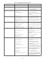
Table 9 - Tubular Blower Troubleshooting Guide
SYMPTOMS
POSSIBLE CAUSE(S)
CORRECTIVE ACTION
A. Flame pops back.
1. Burner orifice too small.
1. Check with local gas supplier for proper orifice
size and replace. Refer to "Gas Input Rate."
B. Noisy Flame.
1. Irregular orifice causing whistle or resonance.
1. Replace orifice.
2. Excessive gas input.
2. Test and reset manifold pressure (see Table
4 - "Gas Piping Requirements").
1 Clogged main burners.
1. Clean main burner ports.
2. Misaligned orifices.
2. Replace manifold assembly.
3. Insufficient combustion air.
3. Refer to "Installation - Clearances" and
"Venting" to ensure unit is properly mounted
and vented.
4. Possibly over fired.
4. Check gas input and manifold pressures.
1. Blocked venting.
1. Clean flue. Refer to "Installation."
2. Insufficient combustion air.
2. Clean combustion air inlet openings.
3. Blocked heat exchanger.
3. Clean heat exchanger. Refer to "Installation."
4. Air leak into combustion chamber or flue
collector.
4. Determine leak and repair accordingly.
1. Gas leak. Shut off gas supply immediately!
1. Inspect all gas piping and repair accordingly.
2. Leaking gas test port on valve.
2. Check to ensure gas test ports are sealed.
3. Blocked heat exchanger.
3. Clean heat exchanger. Refer to "Installation."
4. Blocked flue collector.
4. Clean flue collector. Refer to "Installation."
5. Negative pressure in the building.
5. See "Installation."
1. Improper ground.
1. Check grounding wires and spark bracket
connections.
2. Bad or broken spark cable.
2. Inspect spark cable connections and cuts.
Replace if necessary.
3. Faulty control.
3. Check to ensure spark is energized after prepurge period.
4. Pressure regulator set too low.
4. Test and reset manifold pressure.
5. Main burner orifices dirty.
5. Clean or replace orifices.
6. Improper venting.
6. Refer to "Installation."
1. Gas leak. Shut off gas supply immediately!
1. Open all manual valves, check for leaks.
2. No power supply to unit.
2. Turn on power supply, check fuses and
replace if bad.
3. Thermostat not calling.
3. Turn up thermostat. Check for 24V on
terminals R and W1 on terminal strip.
4. Defective high limit.
4. Check switch for continuity if open with no
heat present; replace.
5. Defective draftor prove switch.
5. Check switch operation to ensure switch
closes after draftor purge period. If it does not
make, check tubing connections for blockage.
6. Defective spark ignitor, gas valve, thermostat
or transformer.
6. Check for continuity and voltage in safety
and control circuits; replace an item where
continuity or voltage not found.
7. Loose wiring.
7. Check all wiring per diagram.
8. Improper ground.
8. Check all ground wires and connections.
9. Improper thermostat or transformer wiring.
9. Check both for wiring according to diagram;
check for 24V at gas valve terminals during
trial for ignition period. If present and valve
does not open, replace valve.
C. Yellow tip flame (some yellow
tipping on LP gas is permissible).
D. Floating flame.
E. Gas odor
F. Delayed ignition.
G. Failure to ignite.
26
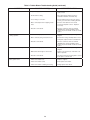
Table 9 - Tubular Blower Troubleshooting Guide (continued)
SYMPTOMS
H. Condensation.
I. Burners will not shut off.
J. Rapid burner cycling.
K. Blower will not run.
L. Blower motor turns on and off while
burner is operating.
M.Blower motor will not stop.
POSSIBLE CAUSE(S)
CORRECTIVE ACTION
1. Improper venting.
1. Refer to "Installation."
2. Unit under fired.
2. Check gas supply pressures to unit. Refer to
"Installation."
3. Building/space too cold.
3. Refer to "Installation."
1. Thermostat located improperly.
1. Relocate thermostat away from outside wall
or drafts.
2. Improper thermostat wiring.
2. Check thermostat circuit for open and close
on heater terminal strip "R" and "W."
3. Shorted circuit.
3. Check thermostat circuit for shorts or any
staples piercing wires.
4. Defective thermostat.
4. If thermostat is calling after set point has
been satisfied, replace.
5. Defective/sticking gas valve.
5. Check for 24V on gas valve terminals when
thermostat not calling. Replace if necessary.
6. Defective control board.
6. Check for 24V at terminals "R" and "W." If not
present and board is not in flash code mode,
replace board.
7. Excessive gas supply pressure.
7. Refer to "Pipe Installation" and Table 4 - "Gas
Piping Requirements."
1. Loose electrical connections at thermostat or
gas valve.
1. Tighten all electrical connections.
2. Excessive thermostat heat anticipator setting.
2. Adjust heat anticipator setting for longer
cycles. Refer to "Electrical Connections."
3. Unit cycling on high limit.
3. Check for proper air supply across heat
exchanger and proper gas supply.
4. Thermostat located improperly.
4. Relocate thermostat away from outside wall
or drafts.
1. Loose electrical connections.
1. Check and tighten wires on blower circuit.
2. Defective motor or overload.
2. Test for 115V on terminal ACB Heat and "L2."
If voltage is present, replace motor.
3. Defective control board.
3. Test for 115V on terminal ACB Heat and "L2."
If voltage is not present 45 seconds after trial
for ignition, replace board.
4. Contactor or starter overload tripped.
4. Test for 115V on coil of contactor. Check if
overload has tripped; reset. Check amp draw
to motor. Check incoming for power and
contactor operation.
5. Broken belt.
5. Replace belt.
1. Motor overload protection is tripping.
1. Check motor amp against the motor name
plate, check voltage, replace if found
defective.
2. Loose wiring or connection.
2. Check for 115V between motor leads.
3. Control board is defective.
3. Check terminal ACB Heat for voltage. If
voltage not constant, replace board.
1. Control board is in flame failure mode.
1. Turn 115V power off to the unit, wait 10
seconds and reapply voltage to the unit.
2. Improperly wired blower circuit.
2. Check wiring of blower circuit to wiring
diagram.
3. Control board is defective.
3. If unit is not calling for heat and board is not
in flash code mode, replace board.
27
Table 9 - Tubular Blower Troubleshooting Guide (continued)
SYMPTOMS
N. Not enough heat.
O. Too much heat.
P. Noisy blower/motor.
Q. Cold air is delivered during heater
operation.
R. High limit is tripping.
POSSIBLE CAUSE(S)
CORRECTIVE ACTION
1. Incorrect gas input.
1. Refer to "Gas Input Rate"
2. Heater undersized.
2. Is the heater output sized correctly for the
heat loss of the space? Has the space been
enlarged? Is the heater located in the space
properly (see "Installation")?
3. Thermostat malfunction.
3. Check thermostat circuit; 24V on terminals
"R" and "W" on terminal strip.
4. Heater cycling on limit.
4. Check air movement across heat exchanger.
Check voltage and amps at the blower motor.
Check gas input to ensure unit is not over
fired. Check heat exchanger to ensure unit is
not dirty.
5. Incorrect orifice sizes.
5. Check orifice size (Refer to "Gas Input Rate"),
replace if necessary.
1. Unit is over fired.
1. Refer to "Gas Input Rate." Check orifice size.
Replace if too large.
2. Thermostat malfunction.
2. Check thermostat for operation, to ensure
circuit open and closes.
3. Heater runs continuously.
3. Check wiring per diagram. Check operation at
the gas valve. Look for a short in thermostat
circuit.
4. Defective gas valve.
4. Replace valve and check pressure setting
(See Table 4 "Gas Piping Requirements").
5. Excessive gas supply pressure.
5. Refer to "Pipe Installation" and Table 4 - "Gas
Piping Requirements."
6. Excessive static pressure.
6. Adjust blower sheave to correct RPM - See
"Blower Set Up and Adjustment."
1. Blower wheel loose.
1. Replace or tighten.
2. Blower wheel is dirty.
2. Clean blower wheel.
3. Blower wheel is rubbing on housing.
3. Realign blower wheel.
4. Bearings are dry.
4. Oil bearings on blower motor. (Refer to label
on motor.)
5. Pulley is loose.
5. Check Blower and Motor pulleys. Replace or
tighten as necessary.
1. Incorrect manifold pressure or input.
1. Test and reset manifold pressure (see Table
4 - "Gas Piping Requirements").
2. Air throughput too high.
2. Check Blower and Motor pulleys. Replace or
tighten as necessary.
1. Unit is over fired.
1. Refer to "Gas Input Rate." Check orifice size.
Replace if too large.
2. Air flow is too low.
2. Check for proper voltage; ensure blower
assembly is correct.
3. Defective high limit.
3. Check operation of switch. If switch is open
during operation, check gas pressure and/
or CFM; adjust accordingly. If switch is open
during start-up, replace switch.
4. Defective control board.
4. Check for 24V on line side of high limit.
Constant voltage should be recorded. If not,
control board is suspect. Check flash code.
28
Table 9 - Tubular Blower Troubleshooting Guide (continued)
SYMPTOMS
S. Power ventor will not run.
T. Power ventor turns on and off
during operation.
U. Power ventor will not stop.
V. Noisy power ventor.
POSSIBLE CAUSE(S)
CORRECTIVE ACTION
1. No power supply to unit.
1. Turn on power supply, check fuses and
replace if bad.
2. Thermostat not calling.
2. Turn up thermostat. Check for 24V on
terminals R and W1 on terminal strip.
3. Loose wiring or connection.
3. Check all wiring in the power vent circuit to
ensure good connection, including "Neutral."
4. Motor overload protection is tripping or bad
motor.
4. Check for 115V between motor leads
and check amp draw of motor. Replace if
necessary.
5. Defective control board.
5. Check for continuous 115V on terminal
"CBM" Blower" and neutral during call for
heat. If not present and all checks are normal,
replace.
1. Power ventor improperly wired.
1. Check power ventor circuit per wiring
diagram.
2. Motor overload cycling or defective motor.
2. Check motor voltage and amp draw to motor
name plate, replace if motor found defective.
3. Defective control board.
3. Check for continuous 115V on terminal
"CBM" Blower" and neutral during call for
heat. If not present and all checks are normal,
replace.
1. Power ventor improperly wired.
1. Check power ventor circuit per wiring
diagram.
2. Main burner did not light on call for heat.
2. Heater is in lockout mode; check flash code
table for problem.
3. Defective control board.
3. If no flash codes present along with no call for
heat, replace control board.
1. Power ventor wheel loose.
1. Replace or tighten.
2. Power ventor wheel is dirty.
2. Clean power ventor wheel.
3. Power ventor wheel is rubbing on housing.
3. Realign power ventor wheel.
29
Table 9A - Tubular Blower Troubleshooting with LED Indicator Assistance
No Cycling or appliance power
or thermostat call for heat
since appliance failure has
occured.
Line voltage power can
cause product damage,
severe injury or death.
Only a trained experienced
service technician should
perform this troubleshooting.
1. Check the system thermostat to make sure it is calling for heat. (Do not cycle
the thermostat on and off at
this time.)
2. Remove the appliance
burner compartment door.
Do not interrupt power
to the control board by
opening any electrically
interlocked panels.
3. Observe the LED indicator
on the control board (a
greem LED labeled “OK”
indicates system faults);
check and repair system
as noted in the chart to the
right.
*NOTICE: Air flow proving
switch and power ventor
hose barbs must be free
of any dust or debris at all
times. Periodically check
these openings and/or if any
problems occur.
INDICATES
LED STATUS
CHECK/REPAIR
Slow Flash
Control OK, no call for heat.
Not Applicable
Fast Flash
Control OK, call for heat present.
Not Applicable
Steady Off
Internal control fault, or no power.
1. Line voltage on terminals 120
and C on transformer.
2. Low voltage (24V) on terminals
24 and C on transformer.
3. 5 Amp fuse on circuit board.
Steady On
Control internal failure or bad ground.
1. Common side of transformer
grounded to chassis.
2. Loose spark ignitor.
2 Flashes
In lockout from failed ignitions
or flame losses.
1. Gas supply off or gas supply
pressure too low.
2. Flame sense rod contaminated
or loose wire.
3. Gas valve switch is off or wires
are not connected.
4. Broken or cracked porcelain on
flame probe or spark ignitor.
3 Flashes
Pressure Switch open with inducer on
or closed with inducer off.
1. Obstructions or restrictions
in appliance air intake or flue
outlet are preventing proper
combustion airflow.
2. Moisture or debris in tubing that
connects pressure switch and
draft inducer.
3. Airflow switch jumpered or
miswired.
4 Flashes
Limit or rollout switch is open.
1. Open manual reset rollout switch.
2. Gas pressure too high, over fire
condition.
3. Incorrect airflow due to blockage
or motor not operating.
5 Flashes
Flame sensed while gas valve is off.
1. Flame probe miswired
or shortened.
6 Flashes
On-board microprocessors disagree.
1. Thermostat is interfering
with control board.
30
MAINTENANCE
PERIODIC SERVICE
NOTICE: The heater and vent system should be
checked once a year by a qualified technician.
2. Turn off the manual gas valve and electrical power to
the unit heater.
3. To clean or replace the burners, remove burner
cover. Remove top strip from above burners. Lift
burners up and pull away from manifold to remove.
4. With the burners removed, wire brush the inside
surfaces of the heat exchanger.
5. Remove any dirt, dust, or other foreign matter from
the burners using a wire brush and/or compressed
air.
6. Reassemble the unit heater by replacing all parts in
reverse order.
7. Check the burner adjustment.
8. Check all gas control valves and pipe connections for
leaks.
9. Check the operation of the automatic gas valve by
lowering the setting of the thermostat, stopping the
operation of the gas duct furnace. The gas valve
should close tightly, completely extinguishing the
flame on the burners.
10. Inspect and service motor/blower assembly. To
maintain efficient air flow, inspect and clean the
blower blades and housing to prevent buildup of
foreign matter.
11. Check motor lubrication. If oiling is required, add 1 or
2 drops of electric motor oil as follows:
a. Light Duty - After 3 years or 25,000 hours of
operation.
b. Average Duty - Annually after 3 years or 8,000
hours of operation.
c. Heavy Duty - Annually after 1 year or at least
1500 hours of operation.
All Maintenance/Service information should be recorded
accordingly on the Inspection Sheet provided in this
manual.
Open all disconnect switches
and disconnect all electrical and gas supplies
and secure in that position before servicing unit.
Failure to do so may result in personal injury or
death from electrical shock.
Gas tightness of the safety shutoff valves must be checked on at least an annual
basis. Failure to do so may result in death,
serious injury or substantial property damage.
To check gas tightness of the safety shut-off valves,
turn off the manual valve upstream of the appliance
combination control. Remove the 1/8" pipe plug on
the inlet side of the combination control and connect
a manometer to that tapping. Turn the manual valve
on to apply pressure to the combination control. Note
the pressure reading on the manometer, then turn the
valve off. A loss of pressure indicates a leak. If a leak
is detected, use a soap solution to check all threaded
connections. If no leak is found, combination control is
faulty and must be replaced before putting appliance
back in service.
Should maintenance be required, perform the following
inspection and service routine:
Never over oil the motor or premature
failure may occur! Over oiling the motor may result
in minor injury or property damage.
1. Inspect the area near the unit to be sure that there is
no combustible material located within the minimum
clearance requirements listed in this manual.
12. Check and test the operational functions of all safety
devices supplied with your unit.
Under no circumstances should
combustible material be located within the
clearances specified in this manual. Failure to
provide proper clearance could result in personal
injury or equipment damage from fire.
31
LIMITED WARRANTY
Power Vented Tubular Blower Unit Heaters
1. The "Manufacturer" warrants to the original owner at original installation site that the above model Gas-Fired
Heater ("the Product") will be free from defects in material or workmanship for (1) year from the date of shipment
from the factory, or one and one-half (1-1/2) years from the date of manufacture, whichever occurs first. The
Manufacturer further warrants that the complete heat exchanger, flue collector, and burners be free from defects
in material or workmanship for a period of ten (10) years from the date of manufacture. If upon examination by
the Manufacturer the Product is shown to have a defect in material or workmanship during the warranty period,
the manufacturer will repair or replace, at its option, that part of the Product which is shown to be defective.
2. This limited warranty does not apply:
a. if the product has been subjected to misuse or neglect, has been accidentally or intentionally damaged, has
not been installed, maintained, or operated in accordance with furnished written instructions, or has been
altered or modified in any way by any unauthorized person.
b. to any expenses, including labor or material, incurred during removal or reinstallation of the Product
c. to any damage due to corrosion by chemicals, including halogenated hydrocarbons, precipitated in the air
d. to any workmanship of the installer of the Product
3. This limited warranty is conditional upon:
a. advising the installing contractor, who in turn notify the distributor or manufacturer
b. shipment to the Manufacturer of that part of the Product thought to be defective. Goods can only be returned
with prior written approval of the Manufacturer. All returns must be freight prepaid.
c. determination in the reasonable opinion of the Manufacturer that there exists a defect in material or
workmanship
4. Repair or replacement of any part under this Limited Warranty shall not extend the duration of the warranty with
respect to such repaired or replaced part beyond the stated warranty period.
5. THIS LIMITED WARRANTY IS IN LIEU OF ALL WARRANTIES, EITHER EXPRESS OR IMPLIED, AND
ALL SUCH OTHER WARRANTIES, INCLUDING WITHOUT LIMITATION IMPLIED WARRANTIES OF
MERCHANTABILITY OR FITNESS FOR A PARTICULAR PURPOSE, ARE HEREBY DISCLAIMED AND
EXCLUDED FROM THIS LIMITED WARRANTY. IN NO EVENT SHALL THE MANUFACTURER BE LIABLE
IN ANY WAY FOR ANY CONSEQUENTIAL, SPECIAL, OR INCIDENTAL DAMAGES OF ANY NATURE
WHATSOEVER, OR FOR ANY AMOUNTS IN EXCESS OF THE SELLING PRICE OF THE PRODUCT OR
ANY PARTS THEREOF FOUND TO BE DEFECTIVE. THIS LIMITED WARRANTY GIVES THE ORIGINAL
OWNER OF THE PRODUCT SPECIFIC LEGAL RIGHTS. YOU MAY ALSO HAVE OTHER RIGHTS WHICH
MAY VARY BY JURISDICTION.
In the interest of product improvement, we reserve the right to make changes without notice.
32
IDENTIFICATION OF PARTS
BLOWER UNIT HEATERS
Figure 13 - Blower Parts
Figure 14 - Component Parts
Hanger Locations
Flue
Power Vent
Assembly
Belt Guard
Motor
Blower
Baffle (Secondary)
Electrical Control
Panel Assembly
Flame Sensor
Manifold Burner
Assembly
Burner Cover
Vestibule Panel/
Tube Assembly
Ignitor
Gas Valve
Peep Hole Cover
(Burner)
D8927
D8925B
D8927
Figure 15 - Vestibule Panel / Tube Assembly
Figure 16 - Electrical Control Panel Assembly
Accordian Fastener
Pressure Switch
Power Venter
Connection
Transformer
Fan Motor
Connection
Control Board
Base
D8928
Terminal Block
D9064
Electrical Control
Panel Door
D8928
D9064
33
IDENTIFICATION OF PARTS (continued)
Figure 18 - Power Venter Assembly
(300/400 Unit Sizes Shown)
Figure 17 - Power Venter Assembly
(100/250 Unit Sizes Shown)
D4798
D4780
Figure 19 - Turbulator/High Limit Location
Power Venter Ass'y
Vestibule Panel/
Tube Ass'y
Flue Collector
Turbulator
D8926
High Limit Ass'y
D8926
HOW TO ORDER REPLACEMENT PARTS
Please send the following information to your local representative: if further assistance is needed, contact the
manufacturer's customer service department.
• Unit Number
• Serial Number
• Part Description and Number as shown in Replacement parts Catalog
34
TUBULAR BLOWER
UNIT NUMBER DESCRIPTION
Digit
Item
X
X
X
X — 1
Prefix
2
UT
3
4
5
CA
6
7
8
9 10 11 12 13 14 +
FT FM GT AL GC SV MT MS
AS
(Internal use Only)
Digit #1, 2 - Unit Type [UT]
Digit #12 - Motor Type [MT]
TC - Tubular Blower
1 - Open Drip Proof (Standard)
2 - Totally Enclosed
3 - Premium Efficiency, Open Drip Proof
4 - Premium Efficiency, Totally Enclosed
Digit #3, 4, 5 - Capacity [CA]
100 - 100,000 BTU/HR
125 - 125,000 BTU/HR
150 - 150,000 BTU/HR
175 - 175,000 BTU/HR
200 - 200,000 BTU/HR
250 - 250,000 BTU/HR
300 - 300,000 BTU/HR
350 - 350,000 BTU/HR
400 - 400,000 BTU/HR
Digit #13 - Blower Motor Sizes [MS]**
A - 1/4 HP w/Contactor
P - 1/2 HP w/Magnetic Starter
C - 1/2 HP w/Contactor
R - 3/4 HP w/Magnetic Starter
D - 3/4 HP w/Contactor
S - 1 HP w/Magnetic Starter
F - 1 HP w/Contactor
T - 1-1/2 HP w/Magnetic Starter
G - 1-1/2 HP w/Contactor
U - 2 HP w/Magnetic Starter
H - 2 HP w/Contactor
W - 1/4 HP w/Magnetic Starter
J - 1/4 HP
0 - None/Not Applicable
L - 1/2 HP
**Notes: 1. All 3-phase units [SV = 4, 5, 6, 7] include a contactor as standard.
2. All single phase units [SV = 1, 2, 3] include a contactor for units equipped with
3/4 HP. motor or higher [MS = D, F, G, H]
3. [MS] options J, L only available with [SV] option 1 (115/1/60).
Digit #6 - Furnace Type [FT]
A - Right Side Access
Digit #7 - Heat Exchanger Construction Material [FM]
1 - Standard (Aluminized) Steel
2 - 409 Stainless Steel
Digit #14 - Accessories [AS]
Digit #8 - Gas Type [GT]
FACTORY INSTALLED
N - Natural Gas
P - Propane Gas (LP)
M8 - Discharge Duct Flange
S3 - 409 Stainless Steel Flue Collector
S5 - 304L Stainless Steel Burners
P4 - Terminal Block Wiring
P6 - Summer/Winter Switch
Digit #9 - Ignition Control [IC]
S - 0-4,999 ft.
T - 5,000-11,999 ft.
Note: Installations over 2,000 ft. require gas input deration in the field.
Refer to unit installation instructions.
† FIELD INSTALLED (AS-____ )
† Field Installed Accessories are not included in the Unit Number. All Field Installed
Accessories are entered as a separate line item using the catalog number which utilizes
“AS” as a prefix. i.e: A7 becomes AS-A7.
Digit #10 - Direct Spark Gas Control [GC]
1 - Single Stage
2 - Two Stage
3 - Electronic Modulation w/Room Sensing
4 - Electronic Modulation w/Duct Sensing (Blower Only)
5 - Electronic Modulation w/Duct Sensing & Room Ovrd. Stat (Blower Only)
6 - Electronic Modulation w/External 4-20 mA Input
7 - Electronic Modulation w/External 0-10 VDC Input
A7 - Pressure Regulator 1/2-2 psi
F1 - 1-Stage T675A Ductstat (Blower Only)
F2 - 2-Stage T678A Ductstat (Blower Only)
G1 - 1-Stage T87K Mercury Free Thermostat
w/Subbase Kit
G2 - 1-Stage T87K Mercury Free Thermostat
w/TG511A Guard Kit
G3 - 1-Stage T834N Mercury Free Thermostat
w/Fan Switch
G5 - 2-Stage TH5220D Mercury Free Thermostat
w/Subbase
G6 - Locking Thermostat Cover
G8 - 1-Stage T6169C Line Voltage Stat
w/Subbase
G9 - 1-Stage T822K Mercury Free Thermostat
Digit #11 - Supply Voltage [SV]
1 - 115/1/60
5 - 230/3/60
2 - 208/1/60
6 - 460/3/60
3 - 230/1/60
7 - 575/3/60
4 - 208/3/60
Z - Special
Note: Supply Voltages [SV] 2-7 include factory mounted step down transformer.
35
M2-2 - Vent Caps (5 inch) (Unit Capacity 100-250)
M2-3 - Vent Caps (6 inch) (Unit Capacity 300-400)
P5 - 24V SPST Relay-Specify Purpose
X2 - 30 Degree Downturn Nozzle
X3 - 60 Degree Downturn Nozzle
X4 - 90 Degree Downturn Nozzle
X5 - Vertical Louver Kit
GAS EQUIPMENT
START-UP
Customer ____________________________________ Job Name & Number _________________________
PRE-INSPECTION INFORMATION
With power and gas off.
Type of Equip:
Unit Heater
Serial Number _________________________ Model Number __________________________
Name Plate Voltage:
_____________
Name Plate Amperage: _____________
Type of Gas:
Natural
Tank Capacity _______ lbs.
_______ kg
❐
❐
❐
❐
❐
❐
❐
❐
LP
Are all panels, doors, vent caps in place?
Has the unit suffered any external damage?
Damage ______________________________
Does the gas piping and electric wiring appear to be installed in a professional manner?
Has the gas and electric been inspected by the local authority having jurisdiction?
Is the gas supply properly sized for the equipment?
Were the installation instructions followed when the equipment was installed?
Have all field installed controls been installed?
Do you understand all the controls on this equipment? If not, contact your wholesaler or rep.
(DO NOT START this equipment unless you fully understand the controls.)
GAS HEATING
With power and gas on.
GENERAL
With power and gas off.
❐
❐
❐
❐
Make certain all packing has been removed.
Tighten all electrical terminals and connections.
Check all fans & blowers for free movement.
Check all controls for proper settings.
FAN
With power and gas off.
❐
❐
❐
Rating: ______ BTU @ ____ °F
______ kw @ ____ °C
Check voltage L1___ L2___ L3___
Check rotation of main blower.
Check motor amps L1___ L2___ L3___
❐
❐
❐
❐
❐
❐
❐
❐
❐
❐
❐
❐
Inlet gas pressure.
____ in. W.C. or ____ kPa
Burner ignition.
Manifold gas pressure. ____ in. W.C. or ____ kPa
Cycle firestat and/or freezestat.
Check electronic modulation. Set at: __________
Cycle and check all other controls not listed.
Check operation of remote panel.
Entering air temp. _____ °F or ____ °C
Discharge air temp. (high fire) ____ °F. or ____ °C
External static pressure _________ in. W.C.
Cycle by thermostat or operating control.
Combustion Reading:
Carbon Monoxide:____ PPM
Carbon Dioxide:____ %
_____________________________________________
__________________________________________________
__________________________________________________
Remarks:
260 NORTH ELM ST., WESTFIELD, MA 01085
TEL: (413) 568-9571 FAX: (413) 562-8437
www.mestek.com