1
Ie J Y2
owners
manual
MODEL NO.
161.216300
INE ANALYZ
FOR
12
VOLT
OPERATING
Caution:
SAFETY
Read Rules For
Safe Operation
and Complete
TUNE-UP
Operating Test
Procedures
REPAIR
SYSTEMS
INSTRUCTIONS
RULES
PROCEDURES
PARTS
Carefully
IIIII
J_
IIIII .I
I III illll U
III!IIII
L
IllIII
. . I II I
,JJ
.....
II
IJLJIIJIII I III1[
SEARS, ROEBUCK
CH!CAGO,
I IIIIIII
PRINTED
III III
IN U.S.A,
I
I iilliiII
III II
I I IIIIIIIIIIIIIIIIIIII
.
II
IJ
IIIII[
.
l Ill . .
.
I
III
II
AND CO. U.S.A.
ILLINOIS
I
I
60684
IIIIIIIIIIIIIIIIIWHIIIIIIIII
II
II
2-168302
RULES FOR SAFE AUTOMOTIVE
WARNING
TESTING
-- READ CAREFULLY
Read this OperaUon
Manual
and these Rules for Safe
Automotive Testing carefully. Failure to follow instructions
and safety rules could result in sedous bodily injury and/or
damage to the Instrument.
1.
Before starting the engine, set the parking brake and place the
gear selector in NEUTRAL on standard transmissions and
PARK on automatic transmiasionl,
2.
The carbon monoxide m exhaustgas
is highly tOxiC To avoid
asphyxiation,
always operate vehicle in • well-ventilated
ares,
If vehicle ss tn an enclose_l area, exhaust
should
be routed
directly
3
4
to the outside
vie leak-proof
exhaust
contact
with
battery
electrolyte
Electrolyte
batteries
should
of exploswe
gases
be
To
To avoid the possibility
of a flash fire, do not smoke or permit
flame or spark to occur near carburetor,
fuel hne, fuel filter,
fuel pump or other
potential sources
of spdled gasoline or
gasottne vapors
1!
Naver remove radlator cap while the engme
escaping under pressure can cause serious
12
The jack supphed
changing
wheels.
vehicle is on jack.
13.
When
do not disturb the baltery charger connections
is charging, and always turn charger off before
Never add acid to a battery once the battery has been placed
service; doing
so may result
_n dangerous
spattering
electrolyte.
Never look directly into carburetor throat whde engine _s
cranking or running A sudden backfire can cause serious
burns.
ts hot, Hot coolant
burns.
with the vehicle should be used onty for
Never crawl under car or run engine while
mak=ng electrical
test connect=ons
to the vehicle, do nol
usa the carburetor
or other fuel system components
ground connection,
as a spark could _gn=te the gasoline
and cause a fire or an explosion
disconnecting
the battery chps
When removing
or reconnecting
battery
cables, make sure =gnition
switch and all
accessories
are turned
off
A techmque
used by many
mechanics
_s to carefully
blow across
the top of the baltery
to remove any hydrogen
gas accumulation
before connechng
or disconnecting
battery clips
6.
mamfotd, redactor or high-voltage
10
seek
The gases generated
by a charging battery are highly explosive Do not smoke or permit flame or spark Io occur
near a
battery at any hme, particularly
when _t =scharging. Any room
avoid sparks,
while battery
Oo not tuch hot exhaust
9
can burn
with targe quanhhes of clean water; m case of eye contact,
medical atd immediately
or compartment
containing
charging
well ventilated to prevent accumulation
8.
hose.
holes m clothing, burn skin and cause permanent
damage to
eyes Always wear splash-proof
safety goggles when work=ng
around the battery
tf battery electrolyte rs splashed m the eyes
or on skin. immediately
flush the affected area Ior 15 minutes
5.
Keep hands, hair, neckbe, loose clothing and test leads well
away from fan blades, fan belt, power steering belt, air condrtioner belt and other moving engine parts as serious injury
Could result from entanglement.
spark plug and Cod terminals Spark voltages are not normally
lethal, but an involuntary lark of the hands or arms caused by
electrical shock may result =n,nJury.
An automobile
battery is capabfe
of producing
very high
currents
Therefore,
exercise
reasonable
care when working
near the battery to avoid electrical
connections
through tools,
wristwatch, etc
Avoid
7.
14
Do not let test
engine parts,
cables
rest or tall
on or near
15
Use cauhon when d=sconnectmg
rgmhon
carefully
at the boot w_th the pr'oper tool
as a
vapors
hot or mowng
cables
Pull cables
=n
of
IMPORTANT
THIS MANUAL
PRESENTS
COMPLETE
HOOKUP
INSTRUCTIONS
FOR THE SEARS 161.2163 ENGINE ANALYZER.
IT ALSO
DESCRIBES
MANY OF THE TESTS THAT
THIS INSTRUMENT
IS CAPABLE
OF PERFORMING
AS WELL AS WHEN THEY
SHOULD
BE USED
BASED
ON VEHICLE
PERFORMANCE,
TUNE-UP
OR TROUBLE
ENCOUNTERED.
CONSULT
YOUR
VEHICLE
SERVICE
MANUAL
FOR
SPECIFIC
TUNE-UP
INFORMATION
AND
TEST
PROCEDURES.
FOLLOW
THE
MANUFACTURER'S
SPECIFICATIONS
AND TEST
PROCEDURES
FOR ADJUSTING
DWELL
ANGLE
ESPECIALLY
ON VEHICLES
WITH MODERN
ELECTRONIC
IGNITION
AND EMISSION
CONTROLS.
DO
SERVICE A VEHICLE
WITHOUT
THE MANUFACTURER'S
INSTRUCTIONS
AND SPECIFICATIONS,
VEHICLE
MANUAL, SOURCES
FOR SERVICE
AND
NOT
IDLE SPEED,
ATTEMPT
TO
INFORMATION.
The following is a tiStof publishers who have service manuals for your specific vehicle at nominal cost.
Write to them for availability and prices, specifying the make, style, and model year of your vehrcle.
Amedcan Molora Corporallon
Myr=ad
8835 General Drive
Plymouth Township
M_ch_gan 48170
Ch ry$1er Corporation
Dyment D_Stnbution
Service
Service Publication
20026 Progress Drive
Strongevdle, Ohio 44136
Fgcd Publication
Department
Hblm Incorporated
Post Office Box 07150
Detroit, Michigan 48207
Buick
OTHER
Tuar Company
Post Office Box 354
Fhnt, M_chigan 48501
Oldsmobile
Lansing L=thographers
Post Office Box 23188
Lansing.
Michigan
48909
Cadillac, Chevrolet,
Pontiac
Helm incorporated
Post Office Box 07130
Detroit,
Michigan
48207
Domestic
Chdton
ChHton
Radnor,
SOURCES
- Nonfactory
and Impod
Cart
Book Company
Way
PA 19089
Cordura
Publications
M_tchell Manuals, Inc.
Post Office Box 26260
San Diego, CA 92128
Motor's Auto Repair Manual
Hearst Company
250 W 55th Street
New Yo_k, N Y 10019
ENGINE ANALYZER
CONTROLS,
CONNECTIONS,
AND ACCESSORIES
Q
ANGE SELECTOR
This selects the Dwell or Points/Low
(_
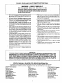
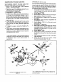
DESCRIPTION.
The Model
161.2163
Engine
Analyzer has a clearly labeled meter and controls as
shown in the Master Hookup diagram, Figure 1 below.
QMETER
This meter displays the following scares:
• RPM
= Volts
0-6000
0.1200
0-16
(_
• Dwell 0-45 degrees (8 cylinder)
0-90 degrees (4 cylinder)
0-60 degrees (6 cylinder)
GM C_3 system Mixture Control
Duty Cycle Solenoid also uses the
0-60 degrees scale.
• Low Volts 0-3.2
Q
ETER ZERO ADJUSTER
Before connecting
any leads to the engine, rotate the
adjuster slowly with a screwdriver
until the pointer
is on zero,
@ FUNCT1ON SELECTOR
This selects the Volts, Amps, Dwell/Points,
8 cytinder RPM functions of the analyzer.
DWELLiRPM/C-3/POINTS/LOW
VOLTS LEAD
The Green clip is used for measuring
Dwetl, RPM,
General Motors C-3 Mixture Control Solenoid Duty
Cycle, Points Resfstance, and Low Volts. For Dwell,
RPM and Points Resistance
testing, connect
this
clip to the negative (-) side of the ignition coi! in Figure
i and 3 through 10, Connections
for other tests will be
* shown and described in specific test procedures.
• Points OK/Bad/Open
• Amps 0-!00
Q
Volts lunctions
of the analyzer, as well as the 0-1200 or 0-6000 RPM
ranges.
BATTERY LEAD
The Red clip is connected to the positive (+) battery
terminal, and the Black clip is connected to a clean,
secure engine ground. For safety reasons, do not use
the negative (-) battery terminal or any fuel system
components
for ground
connections.
Vapors or
gasses in these areas can cause an explosion
if a
spark occurs during connection.
The Red and Black
clips should be connected as shown for all tests.
AMPS LEAD AND SHUNT
The Amps Lead and shunt are used for measuring
alternator
output. To maintain simplicity
in overall
analyzer usage, connect this lead only when measuring alternator output,
page 7, "AMP LEAD AND
SHUNT HOOKUP REQUIREMENT"
and 4, 6, or
STEP 9
GREEN
ALTERNATOR
OUTPUT
W!RE
COIL
REFER TO "AMP LEAD AND SHUNT
HOOKUP
REQUIREMENT"
SECTION,
STEPS AS
INDICATED,
PAGE 7
BATTERY
DISTRIBUTOR
Sears
STEPS 2 --S
161.2163
Master
FIGURE
Hookup
1
Diagram
1+ GM HEI ADAPTOR
The GM HEt Adaptor is used to provide Connection to
the "TACH" terminal on GM HEt systems. See Figure 7
for typical installation.
2+ GM DIAGNOSTIC ADAPTOR
3.
ACCESSORIES
The GM Diagnostic Adaptor is used to make connection to vehicles equipped with the GM Diagnostic
Connector, (1976 - 1982). It is also used'to make connection to Toyota vehicles which use the tlA (Integrated Ignition Assembly). See Figures 9 and 10 for
installatiOn.
FORD COIL CLIP
The Ford Coil Clip is used for ignition systems which
have booted ignition coil connectiOnS. See Figure 4
for installation,
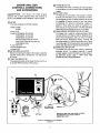
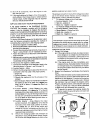
FIGURE 2
PRIMARY
TACH
CONNECTIONS
TO
BALLAST
GREEN CLIP
GREEN
CLIP
BAT.)
COIL
CONTROL
UNIT
TO CONTROL
UNIT
PRIMARY TACH CONNECTION
-- GREEN Clip
At! Chrysler Corporation Electronic ignition,
,6 & 8 Cylinder shown 1972 - 1985
PRIMARY TACH CONNECTION
-- GREEN Clip
Ford Solid State & DuraSpark Systems 1975 • 1985
+ FIGURE 3
FIGURE $
.............................
TO IGN.
SWITCH
,,,,r,,
.TO DIST,
GREEN___
INCLUDED
ADAPTER
]
PRIMARY TACH/DWELL CONNECTION
_ GREEN Clip
1974 Ford Electronic and All
Breaker Potnls Ignition Systems
PRIMARY TACH CONNECTION -- GREEN Clip
FOrd TFI Systems 1981 - 1985
FIGURE 4
FIGURE 6
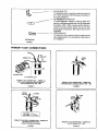
-)TOIGNITION
SWITCH
DELCO
HEI
WITH
INTEGRAL
COIL
INSERT
DIAGNOSTIC
ADAPTER
l
AOAPTER
PRIMARY
TACH CONNECTION
Delco HEr 1974.
FIGURE
_
1985
GREEN
_'. _,._
Clip
REMOVE
CAP FROM
GREEN
TACH TEST
CONNECTOR
7
PRIMARY
Toyota
TACH
CONNECTION
IIA (Integraled
Ignition
_
GREEN
Assembly)
Clip
1983 - 1985
F}GURE t0
Note:
This is NOT
DWELL
PRIMARY
TACH CONNECTION
-- GREEN
Delco HE! i9741985 External Coil
FIGURE
a Tach Connection
CONNECTOR
Clip
SPADE
TERMINAL
ADAPTER
GM
TA(_H
(GREEN)
a
GREEN
CLIP
PRIMARY
polnl.
CONNECTION
_
GREEN
GM Dia_lnosfic Conneclor
and
Delco HEI Syslems !976 - 1982
FIGURE
9
Clip
/
I
GREEN
C3
(Computer
Command
Pertormance
Check
CLIP
or Ground
Jumper
_:IGURE
_
Control)
ONLY
See Vehicle
11
Service
Manual
ELECTRICAL
SYSTEM-PRELIMINARY
CHECKS
E.
INTRODUCTION.
Before performing
any electrical
system tests, carefully read the following information.
These checks will help you to identify the more common
electrical system problems and will serve as a general
guide formaking electrical system tests.
VEHICLE CHECKS.
A,
CONSULT
THE VEHICLE
MANUAL
OF THE
VEHICLE
BEING TESTED
FOR SPECIFIC
VOLTAGE AND CURRENT SPECIFICATIONS
AND TEST
PROCEDURES.
B,
Check the fan belt; tension
facturer's specifications.
C,
Check the generator or alternator pulley and mounting bolts. They should be tight. Make sure that the
charging and cranking system wiring and the battery
cables are in good condition and that connections
are clean and tight. Make sure that the battery is clean
and that the liquid level in each cell is above the plates
on vent-cap style batteries or that the green "eye" is
visible on maintenance-free batteries,
g.
it according
to the manu-
Check the "CCA" (Cold Cranking Amps) rating of the
vehicle battery, often listed on the battery.
This
number should equal or exceed the specification
given by the manufacturer
for the vehicle's engine.
If the battery capacity is too small, a cord engine may
crank slowly or not at all on very cold days. If specifications are not available, the following method may
be used to determine
the recommended
battery
capacity:_
8 CYLINDER ENGINES, The cubic inch displacement (CID -- not liters) equals the Cold Cranking
Amp requirement.
For e _ample, a 350 cubic inch
displacement
engine equals a 350 CCA minimum.
For cold climates, add 20% of the cubic inch dis-
•
ptacement to the CCA. Therefore, 350 x .2 (20%) =
70, 350 + 70 = 420. A 420 CCA or greater rated
battery should be uSed.
6 CYLINDER ENGINES. Calculate the Cubic inch
displacement
per cylinder and multiply by 8. For
example a 231 cubic inch displacement
6 cylinder
engine = 38.5 cubic inch displacement
per cylinder,
Then, 38,5 x 8 = 308 CCA minimum,
For cold climates, add 20% of the adjusted cubic inch displacement to the CCA. Therefore,
308 x .2 (20%) = 62.
308 + 62 = 370. A 370 CCA battery or greater should
be used.
•
4 CYLINDER
ENGINES.
Multiply the cubic inch
displacement
of the engine
by 2. For example, a
t51 cubic inch displacement
engine x 2 = 302 CCA.
For cold climates, add 20% of the adjusted cubic
inch displacement
to the CCA. Therefore, 302 x .2
20% = 60. 302 + 60 = 362. A 362 CCA or greater rated
Check the alternator/generator output rating as listed
on its color-coded tag or _tamped on the alternator/
generator frame. Forexample, 60A or IOOAindicates a
60 Ampere or 100 Ampere alternator/generator. This
rating should equal or exceed the manufacturer's
specification for the vehicle as equipped. An alternator/generator which is elect[ically too small for the
vehicle cannot charge a battery when the vehicle is
run under heavy electrically loaded conditions (lights,
HI fan, air conditioning et¢.) The result.could be a NO
Crank/Start condition after prolonged operation
under heavy electrical load conditions,
F. Electrical specifications are generally given for an
engine which is at normal operating temperature, tf
the ehgine is cold and will start; operate the engine
at idle speed for at least 10 minutes before making any
tests or until it is fully warm (upper radiator hose is
hot). If the engine wil! not start and the cranking
system tests must be made on a cold engine, cranking
voltage may be slightly lower than specificationsstate.
CRANKING
VOLTAGE
AND BATTERY
CONDITION
If the engine cranks slowly or not at afl, the battery,
cranking
motor, and associated
wiring may be at fault.
Check the cranking voltage as indicated below.
1.
Connect the analyzer to the vehicle as shown in Figure
1, and 3 through
!0. The AMP LEAD AND SHUNT
hookup is not necessary for this test.
2.
Disable the engine from starting as explained
vehicte service manual, See Figure 13.
Function SelectorVolts
3
4_
5.
6.
7.
in your
Crank the engine while observing the 16 volt scale on
the analyzer,
Normal Result- 9.6 volts or more at 70 ° F. Voltage will
drop slightly as temperature decreases.
If the results are significantly out of specification
consuit your vehicle
service manual
for further
diagnosis.
If battery voltage remains abnormally
high (above
approximately
10.5 volts) on a slow or no cranking
engine, the problem
may be loose or corroded
connection(s)
in the cranking circuit. Follow the procedure described below.
CRANKING
CIRCUIT
VOLTAGE
LOSS TEST,
THE CRANK1NG CIRCUIT VOLTAGE LOSS TEST
checks for voltage losses in the cranking system,
1. Perform the instructions listed under "Electrical
System -- Preliminary Checks,"
2. Disable the engine from starting as explained in your
vehicle service manual. See Figure 13.
3. Function Selector - Dwell/Points
4. Range Selector - Points/Low Volts
5. Use the Green and Black clipswhile referring to Figure
12. Connect the clips alternately between 1 and 2,
2 and 3, 4 and 5, 4 and 6, 6 and 7, 7 and 8, 7 and 9",
8 and 9, and 8 and !0, Record the results at each point
as read on the 3.2 volt scale of the meter with the
engine cranking.
6. if the meter reads backwards (left of zero) during
testing, reverse the Green and Black clip connections.
7. During this test, no reading should be higher than
0.2 volt.
8. To restart the engine, reverse the "Disabling Pro*
cedure."
9, If any reading is significantly higher than 0.2 volts,"
check the cable or connections involved. Clean and
tighten the connections. Replace broken, cracked or
corroded parts when needed.
" The reading between 7 and 9, the starter solenoid
voltage drop, may be a little h{gher than 0.2 volts and
be satisfactory. Refer to your vehicle manua! for
specifications.
CHARGINL_
_Y_ 1_M VUL i/_L_I;:
It is the function of the charging system to keep the battery
charged when the engine is running and to power the
rest of the vehicle's electrical load requirement (ignition,
lights, fan, etc), If this system fails, the result will be a
discharged or possibly"dead" battery.
!. Connect the analyzer to the vehicle as shownin Figure
!, and 3 through !0, The AMP LEAD AND SHUNT
hookup is not necessary,
2. Function Selector - Volts
3. Start the engine and allow it to warm to normal operating temperature. Operate it at curb idle.
4. With all accessories off observe the 16 volt scale on
the analyzer.
5. Normal Result - 13.2 to 15.2 volts or as specified in the
vehicle service manual,
6, Function Selector - RPM, 4, 6, or 8 cylinder to match
engine under test.
7. Range Selector - O_Y_)O0
RPM
8. Select a step on the fast idle cam which will maintain
engine speed between t800 and 2800 RPM, or have
'an assistant hold engine speed in this range, Hold this
speed through Step 12,
9, Function Selector - Volts
{
10. Observe the 16 volt scale on the analyzer. The voltage
should not have changed from Step 5 more than about
.5 volts,
11. Load the electrical system by turning on the lights,
HI fan, and wipers.
12. Observe the 16 volt scale on the analyzer, Voltage_
should not drop below about 13.0 volts,
NOTE
Cranking
Circuit
Voltage
F|GURE
Loss,
12
Typical
Circuit
This is a representative
Your
vehicle
may use
ponents
or locations,
sample
of one type of cranking
a difle_en_
(_iTcuit with dif|erent
circuit,
com-
13. Shut
off all accessories,
idle, and shut it off.
14. If the results obtained
return
the engine
to curb
in Steps 5, 10, or 12 are signifi -
cantly different from those shown or vehicle service
manual values, further diagnosis
may be required:
see your vehicle service manual.
MISCELLANEOUS
VOLTAGE
TESTS
This analyzer can perform many of the voltage tests called
out in the vehicle service mandal, such as voltages at
lamp sockets, motors, solenoids and relays.
1.
To measure voltage on the 16 volt scale:
+ Function Selector - Volts
/
AMP LEAD AND SHUNT
HOOKUP
REQUIREMENT
If the results obtained in the CHARGING SYSTEM
VOLTAGE Test indicated a problem with the charging
system, it may be necessary to measure the alternator
output current to determine if the alternator is functioning
properly. To do this, follow the test procedure as outlined
in your vehicle service manual; since the procedure is
unique to each vehicle,
To use the 2163 Sears Analyzer for the alternator output
test, the following procedure describes the method of
connecting the current shunt to the charging system.
1, Disconnect negative (-) battery cable.
2. Remove the alternator output wire(s) from the output
terminal of the alternator.
3, Connect the removed wire(s) to the shunt as shown in
Figure 1, using #!0-32 x Vzto _Y4"
hardware as shown.
4, Attach the slotted end of the shunt,to the alternator
output terminal.
5, Make sure all connections are clean and tight and that
NO PART OF THE SHUNT OR CONNECTIONS ARE
TOUCHING VEHICLE GROUND.
6+ Re-connect the negative (-) battery cable.
7. Connect the remainder of the analyzer's leads to the
vehicle as shown in Figures 1, and 3 through i0.
8. Function Selector- Amps
9. Perform the following steps to assure that the shunt is
connected to the Amp Lead in the proper polarity.
1. Engine off.
2. Function Selector- Volts
3. ObserVe the reading on the 16 volt scale of the
analyzer,
4. Start the engine. Wait a few moments and observe
the reading on the 16 volt scare. If it is higher than
Step 3, go to "A" below. !f it is lower than Step 3, go
to "B" below.
"A" FunctiOn Selector - Amps, Observe the meter
pointer movement. If it is above the "O" at the left
hand side of the meter scale, polarity is correct. If it
deflects below "O", shut off the engine and reverse
the "slip on" connections at the shunt. Be careful
not to let pliers or Shunt touch ground when reversing these connections.
"B" Function Selector - Amps, Observe the meter
pointer movement, If it is below the "O +'at the left
hand side of the meter scale, polarity is correct.
If it is above the "O", shut off the engine and
reverse the "3fip on" connections at the shunt. Be
careful not to let pliers or shunt touch ground when
reversing these connections.
10.
Perform the charging system test procedure as
described in your vehicle service manual. Switch
the Function and Range Selectors to obtain other
+
t
Red clip * positive (+)
Black clip - negative (-) ground
•
To measure voltage on the 3.2 volt scale:
Function Selector - Dwell/Points
•
•
•
Range Selector - Points/Low Volts
Green clip + positive (+)
Black clip - Negative (-) ground
2.
NOTE
The voltmeter functions
of this instrument can be used
anywhere the vehicle service manual calls for voltage
measurement
except in those applications
which call
for 10 Megohm input impedance or a digital voltmeter.
i,,,,.,,
'
IGNITION
SYSTEM
TESTS
1.
Primary Coil Voltage
(a) if the engine cranks normally, but does not start,
a low voltage (or no voltage) may be measured at
the coil primary (+ terminal), Look for poor (or no)
connection to the ignition Switch, wiring harness,
or (bulkhead) connectors,
(b) If the engine starts, but dies immediately upon
releasing the key, the ballast resistor may beopen
(or changed value). A fqll explanation
for troubleshooting this problem will be found in your vehicfe
service manual.
2,
Breaker Point Resistance Test (Breaker Point Systems
Only),
Visually check the breaker point and associated wiring
and connections. Check to see that the lead from the
distributor
to the Negative (+) terminal of the ignition
cotl is not damaged (nicked insulation etc.), Remove
the distributor
cap and inspect the breaker points,
Properly adjusted breaker points become light gray
in color in normal use. If they are blued, blackened
or pitted, they have exceeded their normal _ife,
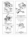
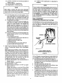
(a) To prevent the engine from starting, disable the
ignition system by grounding
the coil tower wire
as shown below.
ENGINE
GROUND
Disabling
Breaker Point
Ct_t
Procedure,
Ignllion
System
IDC
4
to) L;onnect [ne analyzer to the vehicle as shown in
Figures 1 and 4.
(c) Function Selector - Dwell/Points
(d) Range Selector - Points/Low Volts
(e) It dwelt is within specification no adjustment is
necessary.
,,
There is a direct relationship between dwell end timing.
However, it is onlya one way relationship.If you change
the dwell angle of the breaker points, you will automatically change the ignition timing. Changing the
timing, though, has no effect on the dwell angle. FOR
THIS REASON, IT tS IMPORTANT TO RE-CHECK
THE TIMING WHENEVER THE DWELL ANGLE HAS
BEEN ADJUSTED.
When testing a vehicle with dual points, alternately
block one set of points open with a piece of insulating
material while the other set is being tested.
,
Dwell Test And Adjustment (Breaker Point Systems
Only or Transistorized Systems which Use Breaker
Points).
Before performing the DWELL TEST AND ADJUSTMENT PROCEDURE, read the vehicle emission control label or the vehicle service manual to determine
what should be done with the vacuum hoses connected to the distributor and the various advance/
retard solenoids. Most often, the vacuum hose must
be disconnected from the distributor and the end
plugged with a plastic golf "tee" or other plug.
(a) Connect the analyzer to the vehicle as shown in
Figures 1 and 4.
(b) Function Selector - Dwell/Points
(c) Range Selector - Dwell
(d) Start the engine and allow it to warm up (upper
radiator hose hot),
Operate the #ngine at curb idle OR the RPM
specified by the vehicle emission control label or
the vehicle service manual for measuring dwell.
Check the RPM by switching the FUNCTION
SELECTOR to, the appropriate RPM position to
match the vehicle engine under test, Return the
Function Selector to Dwell and observe the
correct dwell scale.
,,
NOTE
NOTE
(e) Turn the ignition key to the ON position. If the
meter reads OPEN on the points scale, crank the
engine a fraction of a revolution at a time until
the meter reads in the left hand area of the scale.
(f) The points are now closed.
A reading in the OK zone of the points scale indJ*
cares that the breaker points and associated
wiring are in good condition. The Analyzer may
indicate high point resistance on a new set of
points until they have been run tn the vehicle for
a few miles and have been properly seated. This
condition may be ignored as long as any defects
discovered during the previous visual check have
been corrected.
(g) A reading in the BAD zone of the points scale may
indicate defective points or any of the following
faults may exist:
• Poor distributor ground
• Poor connection on the primary lead from the
distributor to the ignition coil
= Defective distributor pigtail lead
= Misaligned points
• Poor points/plate ground inside distributor
Correct the defect and repeat the test,
........
DWELL ADJUSTMENT CONVENTIONAL BREAKER POINT SYSTEMS
On GM distributors with a small metal slide cover, lift the
cover and insert a W' Allen wrench in the adjusting screw
socket and adjust the dwell by turning the wrench, as
shown in Figure 14.
i
....
,,,,,
,
WINDOW
I18" ALLEN
WRENCH
ADJUSTMENT
SCREW
., Ii
TYPICAL GENERAL MOTORS
BREAKER-POINTS DISTRIBUTOR
FIGURE
!4
On Ford, Chrysler, American Motors and other distributors
not equipped with a small metal access slide cover, perform the following steps while referring to Figure 15,
1. Remove coi! wire from center tower of distributor cap
and ground the wire bY connecting the loose end to
the engine or frame.
2. Remove the distributor cap and rotor.
3. Connect a remote starter switch to the vehicle or have
an assistant crank the engine for you,
4. With ignition switch ON and engine cranking observe
reading on the Dwell scale.
5. To adjust Dwelt, loosen the locking screw slightlyand
adjust the point gap with a feeler gauge according to
the procedure outlined in the vehicle service manual.
After adjustment, tighten lOcking screw, and recheck
dwell while cranking engine. Repeat procedure if
necessary. (Figure 15),
Getector a5 follows:
6. Reassemble
distributorand recheckdwellreading
withengineoperating
atidlespeed.
Repeat
steps5 and6if necessary.
A.
For RPM measurement,
*
Function Selector - RPM (4, 6, or 8 cylinder
match the engine under test)
e Range Selector- 0-1200 for idle RPM
0-6000 for High RPM
B,
3,
to
For MiC So{enoid dwell measurement,
Function Selector- Dwell/Points
Range Selector - Dwell
Follow the test procedures as outlined
service manual,
in your vehicle
AU
Slotted Hole
Locking Screw-
Dwelt Ad
(All except
IDelco*Remy
Sliding
Window
Dislrlbutors)
FIGURE 15
DWELL VARIATION TEST
Follow
.
2.
the
introductory
paragraph
and
Steps
a,
through c, of Dwell Test and Adjustment, page 8.
Start the engine and increase the engine speed from
idle to about 1500 RPM and note the dwelt angle.
Return the engine
speed to idle and again
note the
dwell angle; If the difference between the two dwetl
angle readings is more than 3 degrees, check for
excessive wear in the breaker point plate and coup s
ILngs or excessive wear in the distributor
and bushings.
shaft gear
FUEL SYSTEM TESTS
General Motors C-3 (Computer Command Control)
Mixture Control Solenoid Dwelt(Carburetor
equipped vehiclesonly), The G M C-3 system controls
Air/Fue! ratio with a mixture control solenoid in the
carburetor, The basic system performance check of
this systemrequireschecking the duty cycle or"dwell"
of the M/C solenoid, Note that regardless of the
number of cylinders in the engine, the "dwell" reading
is always read on the 6 cylinder dwell scale.
,
Connect the analyzer to the vehicle as shown in
Figures 1,7, 8, 9, and 11. Note that the Green Clip wili
have to be moved from the RPM connection point
(Figures 7, 8. and 9) to the MiC Solenoid connector
(Figure 11) during the test procedure when either
RPM or Dwell measurement iSspecified. It will also be
ENGINE RPM MEASUREMENT
1, Connect the analyzer to the vehicle as shown in
Figures 1, and 3 through 10.
2. Function Selector - 4, 6, or 8 cylinder RPM position
tO match the vehicle under test.
3. Range Selector - 0-1200 or 0-6000 depending on the
engine speed to be measured.
4. Carburetor Adjustments _ There are several adjustments which should be checked as part of a per=
formance tuneup, Those which require engine RPM
monitoring are:
= Curb idle
• E_aseIdle
• Solenoid controlled Idle
• Fast Idle
Your vehicle will likely have some combination of
these adjustments, Proper adjustment of these
settings isa requirement for gOodengine performance
and drivability.
5. Fuel tnjection Adjustments - Some fuel injection
systems have a minimum and maximum authority
adjustment which should be checked during routine
performance tuneup or whenever idle problems are
encountered,
6, Miscellaneous Engine Tests - Many of the test procedures in your vehicle service manual require the
engine to run at a specific RPM during the test. Your
instrument provides excellent monitoring capabilities
for this purpose,
[ .............
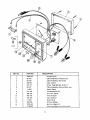
KEY NO.
....
PART NO.
DESCRIPTION
J, , ,, , ,,,,,j,,
, ,,i ......
1
2
i000-252
38-728
Ampere shunt
3
4
38-729
Cable Assembly, Green Clip
400-861
Case, bottom
5
270-117
Screw, Case Self-tap. #6-20 x 1"
6
38-727
7
8
!-1065
210-105
Cable Assembly,
Switch Decal
9
10
290-102
Nut -Hex. 3/8-32
450-128
Knob-Selector
450-133
Cap, Glamour
Meter Decal
11
_
12
i3
1-1064
400-859
14
1000-425
,
Cable Assembly, Ampere shunt
Red and Black clip
Flat Washer 3/8 I.D,
Window (Glass)
Ignition Adapter Kit
Instruction Manual (not illustrated)
2-168302
10
II
[
IIII
I
I IIIIIIIIII
I[
...................
II
II
I
I
IIIIIIIIIIIIIIII
I III
IIIlI
ENGINE
ANALYZER
owners
manual
Now that you have purchased your
ENGINE
ANALYZERt
should a need ever exist
for repair parts or servicer simply contact any
Sears, Roebuck and Co. stores. Be sure to provide all pertinent
facts when you call or visit.
The model number of your ENGINE
ANALYZER
can be found on the front of the instrument.
MODEL NO.
161.216300
WHEN
GtVE
TO ORDER
REPAIR
THE
PART
•
MODEL
order
Repair
l
III
I1_111111111111
NUMBER
listed
Center
may
and most
PARTS,
ALWAYS
INFORMATION'
•
PART
DESCRIPTION
•
NAME
be
ordered
OF ITEM
from
any
Sears
Sears stores,
PARTS
if the
[I III
NUMBER
parts
Service
REPAIR
FOLLOWING
•
All
HOW
ORDERING
......
parts you
will
need are not
be electronically
Parts Distribution
stocked
locally,
transmitted
to
Center
for
handling.
.....
I
II
II
I
Illll iillll
I Ill II li
II
........
your
a Sears
I
L