1
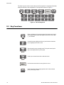
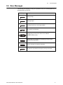
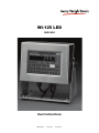
WI-125 LED
Indicator
User Instructions
29629-0018
Issue AR
June 2010
© Avery Weigh-Tronix, LLC 2010. All rights reserved.
No part of this publication may be reproduced, stored in an electronic retrieval system, or transmitted in any form
or by any means, electronic, mechanical, photocopying, recording or otherwise without the prior written consent of
the copyright owner, or as permitted by law or under license. Full acknowledgment of the source must be given.
Avery Weigh-Tronix is a registered trade mark of the Avery Weigh-Tronix, LLC. This publication was correct at the
time of going to print however, Avery Weigh-Tronix, LLC reserves the right to alter without notice the specification,
design, price or conditions of supply of any product or service at any time.
All third party brands and product names used within this document are trademarks or registered trademarks of
their respective holders.
125_LED_u_en_29629_0018.book
Table of Contents
page
Chapter 1 General information and warnings ......................................................................................... 5
About this manual .............................................................................................................. 5
Text conventions ......................................................................................................... 5
Special messages ....................................................................................................... 5
Installation .......................................................................................................................... 6
Electrical installation .......................................................................................................... 6
Pluggable equipment ................................................................................................... 6
Safe handling of equipment with batteries .................................................................. 6
Wet conditions ............................................................................................................. 6
Routine maintenance ......................................................................................................... 7
Cleaning the machine ........................................................................................................ 7
Training .............................................................................................................................. 7
Sharp objects ..................................................................................................................... 7
FCC and EMC declarations of compliance ........................................................................ 8
Chapter 2 Introduction .............................................................................................................................. 9
Operations Mode ............................................................................................................... 9
Keyboard ............................................................................................................................ 9
Key Functions .................................................................................................................. 10
Error Messages ................................................................................................................ 11
Chapter 3 Indicator Operation ................................................................................................................ 12
Powering Up .................................................................................................................... 12
Annunciators .................................................................................................................... 12
Gross / Tare / Net Weighing Operations .......................................................................... 13
Gross Weighing ......................................................................................................... 13
Net Weighing ............................................................................................................. 13
Entering Cutoff Values Through the Front Panel ............................................................. 16
Controlling Cutoffs ........................................................................................................... 17
ID Number Entry .............................................................................................................. 18
Viewing and Setting Time ................................................................................................ 19
Viewing and Setting the Date ........................................................................................... 20
Single Accumulator with Counter ..................................................................................... 21
Weighing and Printing ............................................................................................... 21
Viewing Accumulated Weight and Count .................................................................. 24
Operations Menu ............................................................................................................. 25
Chapter 4 Indicator Diagnostics ............................................................................................................. 26
Test Mode ........................................................................................................................ 26
Chapter 5 Transmitting Data ................................................................................................................... 28
RS-232 Output ................................................................................................................. 28
Communication protocol ............................................................................................ 28
WI-125 LED Indicator User Instructions
3
4
WI-125 LED Indicator User Instructions
1.1
1
General information and warnings
1.1
About this manual
About this manual
This manual is divided into chapters by the chapter number and the large text at the top
of a page. Subsections are labeled as shown by the 1 and 1.1 headings shown above.
The names of the chapter and the next subsection level appear at the top of alternating
pages of the manual to remind you of where you are in the manual. The manual name
and page numbers appear at the bottom of the pages.
1.1.1 Text conventions
Key names are shown in bold and reflect the case of the key being described. If a key
has dual functions, the function is shown first followed by the key name in parentheses
and in bold, such as in these examples: TARE, ZERO, PRINT, etc.
Displayed messages appear in bold italic type and reflect the case of the displayed
message.
1.1.2 Special messages
Examples of special messages you will see in this manual are defined below. The
signal words have specific meanings to alert you to additional information or the relative
level of hazard.
WARNING!
This is a Warning symbol.
Warnings mean that failure to follow specific practices and procedures may
have major consequences such as injury or death.
CAUTION!
This is a Caution symbol.
Cautions give information about procedures that, if not observed, could result
in damage to equipment or corruption to and loss of data.
NOTE: This is a Note symbol. Notes give additional and important information, hints
and tips that help you to use your product.
WI-125 LED Indicator User Instructions
5
General information and warnings
1.2
Installation
NO USER SERVICEABLE PARTS. REFER TO QUALIFIED SERVICE
PERSONNEL FOR SERVICE.
1.3
Electrical installation
CAUTION: The power cable must be connected to an earth-grounded electrical
outlet. The electrical supply must have a circuit breaker with an appropriate
rating to protect from over-current conditions.
For your protection, all electrical (110V or 230V) equipment used out of doors or
in wet or damp conditions should be supplied from a correctly fused power
source and protected by an approved ground fault protection device (RCD,
GFCI etc.)
IF IN DOUBT SEEK ADVICE FROM A QUALIFIED ELECTRICIAN.
1.3.1 Pluggable equipment
Pluggable equipment must be installed near an easily accessible socket outlet.
1.3.2 Safe handling of equipment with batteries
CAUTION: Danger of explosion if battery is incorrectly replaced. Replace only
with the same or equivalent type recommended by the manufacturer. Dispose
of used batteries according to the manufacturer’s instructions.
ATTENTION: Il y a danger d'explosion s'il y a remplacement incorrect de la
batterie, remplacer uniquement avec une batterie du même type ou d'un type
équivalent recommandé par le constructeur. Mettre au rebut les batteries
usagées conformément aux instructions du fabricant.
1.3.3 Wet conditions
Under wet conditions, the plug must be connected to the final branch circuit via an
appropriate socket / receptacle designed for washdown use.
Installations within the USA should use a cover that meets NEMA 3R specifications
as required by the National Electrical Code under section 410-57. This allows the unit
to be plugged in with a rain tight cover fitted over the plug.
6
WI-125 LED Indicator User Instructions
1.4
Routine maintenance
Installations within Europe must use a socket which provides a minimum of IP56
protection to the plug / cable assembly. Care must be taken to make sure that the
degree of protection provided by the socket is suitable for the environment.
1.4
Routine maintenance
IMPORTANT: This equipment must be routinely checked for proper operation
and calibration.
Application and usage will determine the frequency of calibration required for
safe operation.
Always turn off the machine and isolate from the power supply before starting any
routine maintenance to avoid the possibility of electric shock.
1.5
Cleaning the machine
Table 1.1 Cleaning DOs and DON’Ts
DO
DO NOT
Wipe down the outside of standard products Attempt to clean the inside of the machine
with a clean cloth, moistened with water and Use harsh abrasives, solvents, scouring cleaners or
a small amount of mild detergent
alkaline cleaning solutions
Spray the cloth when using a proprietary
cleaning fluid
1.6
Spray any liquid directly on to the display windows
Training
Do not attempt to operate or complete any procedure on a machine unless you have
received the appropriate training or read the instruction books.
To avoid the risk of RSI (Repetitive Strain Injury), place the machine on a surface which
is ergonomically satisfactory to the user. Take frequent breaks during prolonged usage.
1.7
Sharp objects
Do not use sharp objects such as screwdrivers or long fingernails to operate the keys.
WI-125 LED Indicator User Instructions
7
General information and warnings
1.8
FCC and EMC declarations of compliance
United States
This equipment has been tested and found to comply with the limits for a Class A digital device, pursuant to Part 15 of the FCC Rules.
These limits are designed to provide reasonable protection against harmful interference when the equipment is operated in a
commercial environment. This equipment generates, uses, and can radiate radio frequency energy and, if not installed and used in
accordance with the instruction manual, may cause harmful interference to radio communications. Operation of this equipment in a
residential area is likely to cause harmful interference in which case the user will be required to correct the interference at his own
expense.
Canada
This digital apparatus does not exceed the Class A limits for radio noise emissions from digital apparatus set out in the Radio
Interference Regulations of the Canadian Department of Communications.
Le présent appareil numérique n’émet pas de bruits radioélectriques dépassant les limites applicables aux appareils numériques de
la Classe A prescrites dans le Règlement sur le brouillage radioélectrique edicté par le ministère des Communications du Canada.
European Countries
WARNING: This is a Class A product. In a domestic environment, this product may cause radio interference in which the user may be
required to take adequate measures.
8
WI-125 LED Indicator User Instructions
2.1
2
Operations Mode
Introduction
The WI-125 LED is a full featured indicator in a stainless steel enclosure and includes
a numeric keypad. The weight sensor interface termination and RS-232 termination are
made within the enclosure.
This manual is divided into the following main sections:
l
l
l
l
2.1
Introduction
Indicator Operation
Indicator Diagnostics
Transmitting Data
Operations Mode
This manual is valid for Rev. F or higher software.
Operations mode contains all normal weighing operations. In this mode you can view
or set the following parameters if the unit is so configured:
l
l
l
l
l
l
pushbutton tare
quick keypad tare entry
one to ten tare registers (numbered 0-9)
identification number
time
date
Any combination of these items can be secured behind a security code. Any items
secured by the code number can be viewed but not changed unless you enter the
security code.
2.2
Keyboard
The keyboard consists of 16 keys. Five keys provide all the basic weighing functions:
l
l
l
l
l
Tare
G/N
Zero
Print
Units
WI-125 LED Indicator User Instructions
9
Introduction
The other keys are used to access the menus for purposes of accessing information,
testing the indicator, and configuration. The keyboard is shown in Figure 2.1.
Figure 2.1 WI-125 Keyboard
2.3
Key Functions
Enters a pushbutton tare in gross/net operation. During data entry this key is
used to toggle between positive and negative values. Used to enter a dash
(—) in ID numbers.
Accesses the gross weighing mode from any other function and activates
the net weighing mode if a tare is active.
Zeros the scale in gross or net weigh mode. This key also clears keyed in
digits on the display before they are accepted.
Sends a print command and is used to select menu items.
Used to access menus and move among choices in a menu.
Changes the unit of measure during operations mode. Inserts a decimal
point (.) when keying in values.
10
WI-125 LED Indicator User Instructions
2.4
2.4
Error Messages
Error Messages
The following are displays you may see if problems occur or if invalid operations are
attempted with your WI-125:
Display
Description
Overrange weight.
Underrange weight.
Recovering from lock-up or out of range condition.
A-D converter is not functioning.
Corrupted data in the reset menus. See the Service Manual.
(* = RESET, SETUP, or CAL)
Displayed while a key is pressed when attempting to modify a sealed
selection without edit privileges.
Device on serial port is not ready to receive data.
User menu item is protected from changes by security code number.
WI-125 LED Indicator User Instructions
11
Indicator Operation
3
Indicator Operation
3.1
Powering Up
The unit will power up in gross or net weighing mode, depending on what mode the unit
was in when last turned off. All calibration, zero, gross and tare values will be
maintained during power loss.
The indicator display, Figure 2, tells you the status of the indicator through the
appearance of annunciators. In the LCD version, the annunciators are small arrows
pointing to the different labels around the display face. In the LED version they are
small labeled lights on the front panel.
Annunciator
Figure 3.1 Indicator Display
3.2
Annunciators
No annunciators appear while motion is detected.
12
Gross -
Appears when indicator is in gross weighing mode.
Net -
Appears when a tare is in effect and the indicator is in net weighing mode.
Zero -
Appears when the scale is within ±¼ division of zero.
Print -
Appears when the print key is pressed and while data is transmitted.
lb, kg -
Points out the active unit of measure in weighing mode.
WI-125 LED Indicator User Instructions
3.3
3.3
Gross / Tare / Net Weighing Operations
Gross / Tare / Net Weighing Operations
3.3.1 Gross Weighing
To perform gross/net weighing operations, follow these steps:
1.
Power up the indicator.
Indicator powers up in gross or net mode.
2.
If the unit is not in gross mode, press the G/N key once to get to gross mode.
The annunciator illuminates next to gross. See Figure 3.1.
3.
Verify the scale is empty and zero the scale by pressing the ZERO key.
No weight is displayed and the zero annunciator illuminates. See Figure
3.1.
4.
Select unit of measure by pressing the UNITS key.
The units annunciator will point to the chosen unit of measure.
5.
Place weight on the scale.
Gross weight is displayed.
3.3.2 Net Weighing
For net weighing operations a tare needs to be entered. A tare can be entered by three
methods: using the pushbutton tare, using quick keypad tare entry, or selecting a tare
from the tare register (a memory bank of up to ten tares).
Pushbutton Tare
1.
With the scale empty and the indicator powered up in gross mode, zero the
scale by pressing the ZERO key.
No weight is displayed and the zero annunciator illuminates.
You may view the current or active tare value at any time during a weighing process.
From gross or net weighing mode, press MENU, TARE is displayed, then press
SELECT. If a tare value is active, it will be displayed. If no tare value is active, NO
TARE is displayed. Press G/N to return to gross/net weighing mode. Reference the
Operations Menu section for menu details.
2.
Place the weight to be tared on the scale.
The weight of the object is displayed.
3.
Press the TARE key on the indicator.
The weight is tared, the display reads zero and the net annunciator
illuminates.
WI-125 LED Indicator User Instructions
13
Indicator Operation
4.
Add more weight to the scale.
Net weight is displayed.
5.
View the gross weight by pressing the G/N key.
Gross weight is displayed and the gross annunciator illuminates.
6.
Press the G/N key again to see net weight.
Net weight is displayed and the net annunciator illuminates.
Quick Keypad Tare Entry
1.
From weigh mode, enter a tare value using numeric keys 0-9.
Value is displayed as it is entered.
2.
Push TARE.
Net weight is displayed and the net annunciator illuminates.
Selecting a Tare Register
Tare values must be entered in the tare registers before they can be used in weighing
operations. Refer to the section “Entering and/or Changing Values in Tare Registers”
at the bottom of this page.
1.
From gross or net mode, press MENU once or twice, depending on options
enabled, until…
tArE is displayed.
If you wish to scroll through all the tare registers, continue pushing MENU. Stop when
the register you wish to use is displayed.
2.
2.Using the keypad, enter the number of the tare register you wish to use.
(Numbers 0-9 are allowed.)
That register with its tare value is displayed.
3.
With the correct tare register displayed, press G/N.
Tare value is displayed in net mode.
14
WI-125 LED Indicator User Instructions
3.3
Gross / Tare / Net Weighing Operations
Entering and/or Changing Values in Tare Registers
1.
With the gross or net annunciator illuminated, press the MENU key once or
twice, depending on options enabled, until…
tArE is displayed.
See Operations Menu on page 25 for menu details.
2.
Using the keypad, enter the number of the tare register you wish to view.
(Numbers 0-9 are allowed. For this example, tare register 5 will be used.) Key
in numeral 5.
The tare annunciator illuminates and the display shows 5
0,
indicating that register 5 has no value entered. (Your indicator may have
a value in register 5.)
Clearing a Tare Register
1.
You can enter/change a tare value in a register in two ways:
1a.
Key in a tare value: With the desired register number displayed, key in 155 for
this example, then press PRINT/SELECT.
The value 155 is accepted and tArE is displayed.
OR
1b.
Use the pushbutton tare:With the desired register number displayed and the
container on the scale, press TARE.
The register number and (container weight) new tare value are
displayed.
2.
Press MENU to proceed to the next tare register.
3.
Press G/N to return to the weighing mode.
The value is accepted, net weight is displayed and the net annunciator
illuminates.
Clearing the Active Tare
There are two ways to remove the current or active tare weight.
1.
Remove all weight from the scale and press TARE.
The current active tare register is cleared, scale returns to gross mode
and no weight is displayed.
OR
1a.
With the gross or net annunciator illuminated, press MENU, then press
CLEAR.
tArE is displayed, then no tArE is displayed.
WI-125 LED Indicator User Instructions
15
Indicator Operation
2.
Press the G/N key.
Gross weight is displayed and no tare is active.
Net Weighing Operation
1.
After a tare is established, place the indicator in net mode by pressing the G/N
key.
Net annunciator illuminates. Zero weight will be displayed with the
container on the scale.
2.
Place material to be weighed in the tared container on the scale.
Net weight of material is displayed.
3.4
Entering Cutoff Values Through the Front Panel
Follow the steps below to enter a cutoff value. The cutoff output will be ON below the
value entered and OFF equal to or over the value entered.
1.
Push the MENU key until…
Cutoffs is displayed.
2.
Push the SELECT key…
Cutoffs 0 to 7 are displayed.
16
3.
Push the MENU key to scroll through the cutoff channels.
4.
Use the numeric keypad to enter the cutoff values then press the MENU or
SELECT key.
WI-125 LED Indicator User Instructions
3.5
3.5
Controlling Cutoffs
Controlling Cutoffs
The WI-125 Indicator allows you to control the cutoff process from the front panel.
Through the WI-125 you may: enable/disable the cutoff process, continue or interrupt
the operation of a cutoff before its setpoint has been reached, and/or terminate the
process at any time before the last cutoff has been reached.
There are two types of cutoffs in the WI-125: the ingredient cutoff and the setpoint cutoff
(default). With ingredient cutoffs, you tell the indicator the weight of each ingredient you
want and the indicator will call for that much of each ingredient, no matter what the
weight display says. If you want 100 pounds of ingredient #1 and 100 pounds of
ingredient #2, you would enter 100 for cutoff #0 and 100 for cutoff #1.
With setpoint cutoffs, you tell the indicator at what weight display you want the cutoffs
to activate. In other words, if you want 100 pounds of ingredient #1 and 200 pounds of
ingredient #2, you would set the first setpoint cutoff at 100 and the second cutoff at 300
pounds because that is what the weight display will read when you want the actions to
occur.
You can tell which kind has been configured in your indicator by looking at the cutoff
number in the Operations menu shown below. If the cutoff number has a decimal point
following it, the cutoff is a setpoint type. If there is no decimal, it is configured as an
ingredient type.
Some menu items may not appear in your particular situation due to configuration
setup or firmware revision level.
To Access the Control Function
1.
From Gross/Net Weighing Mode, press MENU one time…
Control is displayed.
2.
With Control displayed, press SELECT…
HALtEd is displayed.
WI-125 LED Indicator User Instructions
17
Indicator Operation
To Activate and Control the Cutoffs
There are two ways--Methods A or B--to activate the cutoffs. Method A activates the
cutoffs immediately while displaying the changing weight on the scale, and Method B
allows you to view the weight on the scale before the cutoffs are activated.
Method A:
1.
With HALtEd displayed, press MENU…
run is displayed.
2.
Press SELECT…
r xxxxxx is displayed. xxxxxx represents the weight as it changes on
the scale.
Method B:
3.
With HALtEd displayed, press SELECT…
h xxxxxx is displayed. xxxxxx represents the weight on the scale.
4.
Press MENU…
r xxxxxx is displayed. xxxxxx represents the weight as it changes on
the scale.
To halt active cutoffs
You may halt an active cutoff at any time.
With r xxxxxx displayed, press any key…
h xxxxxx is displayed and cutoffs are halted.
To return to Gross/Net weighing mode
You may return to G/N weighing mode at any time during this process by pressing
GROSS/NET…
Display returns to G/N weighing mode.
3.6
ID Number Entry
See Operations Menu on page 25 for menu details.
You may enter an ID number of up to 8 digits in length. The ID number may include any
combination of the numbers 0 through 9, a dash and a decimal point.
1.
From gross weighing mode, press MENU repeatedly…
id. is displayed.
2.
Press SELECT …
The current ID number is displayed.
18
WI-125 LED Indicator User Instructions
3.7
3.
Viewing and Setting Time
With the current ID number displayed, enter a numerical value for your ID
number using the keypad…
The new ID number is displayed.
4.
After your new ID number has been displayed, press SELECT…
id. is displayed.
5.
Press G/N to return to the weighing mode.
Display returns to gross or net mode.
3.7
Viewing and Setting Time
See Operations Menu on page 25 for menu details.
Your indicator must have the appropriate circuitry and be configured to allow the
following:
1.
From gross/net weighing mode, press MENU repeatedly until …
Hour is displayed.
2.
Press SELECT…
In the 12 hour clock configuration you will see time displayed as hours,
minutes and A for A.M. or P for P.M. (09.40 A). In the 24 hour clock you
will see hours, minutes and seconds (09.40.38).
If you enter an incorrect digit in step 3 below, press ZERO/CLEAR to clear the display
one digit at a time.
3.
To set the 12 hour clock, use the numeric keypad to enter the correct time.
3a.
Key in the time as hh mm.
3b.
Press the TARE key to toggle between AM & PM.
3c.
After the correct time is entered, press SELECT to accept the new time.
Hour is displayed and clock begins.
3d.
Press G/N to return to the weighing mode.
Display returns to weigh mode.
To set the 24 hour clock, use the numeric keypad to enter the correct time.
4a.
Key in time as hh mm ss.
4b.
After the correct time is entered, press SELECT to accept the new time.
Hour is displayed and the clock begins.
WI-125 LED Indicator User Instructions
19
Indicator Operation
4c.
Press G/N to return to the weighing mode.
Display returns to gross/net mode.
3.8
Viewing and Setting the Date
See Operations Menu on page 25 for menu details.
Your indicator must have the appropriate circuitry and HOUR must be enabled
and set correctly to allow the following:
1.
From gross/net weighing mode, press MENU repeatedly until…
dAY is displayed.
2.
Press SELECT…
Depending on the configuration of your indicator you will see the date
displayed in one of three ways:
month-day-year, or
day-month-year, or
year-month-day.
If you enter an incorrect digit, press CLEAR to clear the display one digit at a time.
3.
To change the date, key in the new date using the numeric keypad.
4a.
Press SELECT to return to the operations mode menu…
The old date is replaced with the new date.
OR
4b.
Press G/N to return to gross/net weighing mode.
The date is accepted and dAY is displayed.
20
WI-125 LED Indicator User Instructions
3.9
3.9
Single Accumulator with Counter
Single Accumulator with Counter
There is a single channel accumulator in the indicator. The accumulator will add the
displayed weights automatically and print individual weights and totals on command.
3.9.1 Weighing and Printing
1.
Weigh load…
Indicator displays weight.
2.
Press PRINT…
Weight is printed.
3.
For each additional load weighed, press PRINT…
Each weight is printed individually and the weight is totalled
automatically within the indicator.
Printing the accumulated weight and count can be accomplished at any time during
the weighing process; however, printing these values automatically clears them from
memory! So take care to print the accumulated values only after you have made all
the necessary weighments.
4.
After the last load has been weighed and printed, press MENU, then TARE…
The total weight and count are printed and cleared from memory.
A print/add function will occur if you have autoprint enabled or if a remote Print
command is received by the indicator.
WI-125 LED is configurable for LP02844 labels
Figure 3.2 WP-233 Tape printer sample printout
WI-125 LED Indicator User Instructions
21
Indicator Operation
Sample 1
Orion 1 Label
Sample 3
Orion 3 Label
Sample 2
Orion 2 Label
Sample 4
Barcode Label
22
WI-125 LED Indicator User Instructions
3.9
Single Accumulator with Counter
The following label samples show the "Total" label available when using the ACCUM
function in the WI-125 indicator. See the Single Accumulator with Counter on page 21.
Sample 5
Orion 1 “Total” Label
Sample 6
Orion 2 “Total” Label
Sample 7
Orion 3 “Total” Label
Sample 8
Barcode “Total” Label
WI-125 LED Indicator User Instructions
23
Indicator Operation
3.9.2 Viewing Accumulated Weight and Count
1.
With weight displayed, press MENU until…
ACC is displayed.
2.
Press PRINT/SELECT…
Total weight of all loads is displayed.
3.
Press PRINT/SELECT to toggle back to ACC…
ACC is displayed.
GROSS may be pressed at any time during viewing to return to weighing mode.
4.
Press MENU once…
count is displayed.
5.
Press PRINT/SELECT…
Total number of loads is displayed.
6.
Press PRINT/SELECT to toggle back to count…
count is redisplayed.
7.
Press G/N to return to weighing mode…
Current weight is displayed.
24
WI-125 LED Indicator User Instructions
3.10
Operations Menu
3.10 Operations Menu
Your WI-125 LED may be configured to display some or all of the following functions:
tare, id, time, date, accumlator, and count. These can be viewed and changed if
allowed by the security code. This manual assumes the unit is configured to allow full
access to all functions. You can disable unneeded options. Instructions are in the
Service Manual.
Below is a flowchart and general instructions for moving around the operations mode
menu. The instructions in the preceding sections outlined the steps in detail for moving
around in this menu. Use this flowchart as a quick reference to maneuver through the
operations mode menu.
Figure 3.3 Operations Menu
Press MENU to move Æ in the diagram
Press and hold MENU for 1.5 seconds to move Å in the diagram
Press PRINT/SELECT to move È in the diagram
Press PRINT/SELECT for 1.5 seconds to select new choice and move Ç in the
diagram
Press G/N at any time to save changes and return to gross/net weighing mode
WI-125 LED Indicator User Instructions
25
Indicator Diagnostics
4
Indicator Diagnostics
4.1
Test Mode
The test mode is used to test various functions of the WI-125. The test menu is shown
in Figure 4. Instructions for using the test menu are found below.
Figure 4.1 Test Menu
Press MENU to move Æ in the diagram
Press and hold MENU for 1.5 seconds to move Å in the diagram
Press PRINT/SELECT to move È in the diagram
Press PRINT/SELECT for 1.5 seconds to select new choice and move Ç in the
diagram
Press G/N at any time to save changes and return to gross/net weighing mode
1.
26
Enter the test mode from gross/net operation by pressing and holding the
MENU key until tESt is displayed. SEALEd or unSEALEd is displayed briefly
while you hold the key. If you release the MENU key too soon, press G/N to
return to normal weigh mode and begin again.
WI-125 LED Indicator User Instructions
4.1
Test Mode
2.
Move to the right through the menu selections by pressing MENU briefly. Move
to the left through the menu selections by pressing MENU for 1.5 seconds or
hold down for continuous scrolling.
3.
To move down a level in the hierarchy, press SELECT. Anytime you wish to
get to the next higher level in the hierarchy, press and hold SELECT for
approximately 1.5 seconds or press SELECT whenever End is displayed.
4.
Press MENU to toggle between choices.
5.
Press G/N to return to gross weighing operation at any time.
Below are the specific directions and explanations for the items you see in the test
menu.
VERSION
Under VErSIOn are the Weigh-Tronix part number and revision
number for the software found in your machine. Weigh-Tronix part
numbers are divided into two parts: the prefix and the dash
number. With VErSIOn displayed, press SELECT to view the
prefix, then push MENU to view the dash number. Press SELECT
to return to VErSIOn.
DISPLAY
With diSPLAY displayed, press SELECT and the bottom row of
annunciators turns on. Press SELECT again and a dynamic test
is run. Press MENU to stop the dynamic test or consecutively
press MENU to step through the display test routine. Press
SELECT when the dynamic test is active to return the unit to
diSPLAY.
BUTTONS
With buttonS displayed, press SELECT and an underscore will
appear on the screen. Press any key except MENU to check for
proper key functioning. After testing the buttons, press MENU to
return to the display.
OUTPUTS
These tests allow you to turn the cutoffs on and off automatically
in sequence, under SEQUENCE, or individually, under CUTOFF
0-7. When you exit the outputs test, the cutoffs revert to their
proper condition according to the weight on the scale.
A to D
Displays the analog to digital counts. The span is normally 20000
counts per millivolt per volt. With a calibrator at zero millivolts per
volt, the displayed value should be between -200 and +200. Press
SELECT to return to A to D.
SERIAL
Tells you if the serial output is ready or busy. A jumper connecting
pins DTR to CTS of the serial port will cause REAdY to be
displayed. Press the MENU key and no LOOP is displayed. With
pins XMITT to RECV connected, LOOP is displayed. With them
disconnected, no LOOP is displayed. Press SELECT to return to
SErIAL.
WI-125 LED Indicator User Instructions
27
Transmitting Data
5
Transmitting Data
The WI-125 LED provides an RS-232 output for data transmission to a peripheral
device. Refer to the Service Manual for RS-232 interface connections.
5.1
RS-232 Output
To transmit data, follow these instructions:
If your indicator has a peripheral device connected, from the gross/net weighing mode
press the PRINT key to transmit the selected output(s)…
The PRINT annunciator (See Figure 3.1) will illuminate while data is
transmitted and the data configured to be printed will be output to the
printer. See Figure 5.1 for a sample printout.
5.1.1 Communication protocol
Samples of the default printout for a WI-125 LED are shown in Figure 5.1. This is the
displayed weight (Gross or Net) followed by a carriage return and line feed.
An enquire code can be sent to the WI-125 LED. This will prompt the indicator to send
a standard printout. The default enquire code number is an ASCII decimal 005. This
number can be changed in configuration.
Figure 5.1 Default printout samples
The default settings for serial output are:
28
Busy
Disabled
Baud
1200
Parity
Clear = 8 data, no parity
Stops
1
Stop Bits
Data Bits
Parity
NONE
1 or 2
7 or 8
None
ODD
1 or 2
7
Odd
EVEN
1 or 2
7
Even
SET
2
7
None
CLEAR
1
8
None
WI-125 LED Indicator User Instructions
5.1
WI-125 LED Indicator User Instructions
RS-232 Output
29
Transmitting Data
30
WI-125 LED Indicator User Instructions
Avery Weigh-Tronix USA
1000 Armstrong Dr.
Fairmont MN 56031 USA
Tel:507-238-4461
Fax:507-238-4195
Email: [email protected]
www.wtxweb.com
Avery Weigh-Tronix UK
Foundry Lane,
Smethwick, West Midlands,
England B66 2LP
Tel:+44 (0) 8453 66 77 88
Fax: +44 (0)121 224 8183
Email: [email protected]
www.averyweigh-tronix.com