1
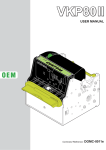
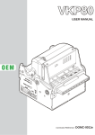
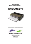
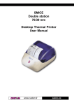
Ultra-Small
Thermal Panel Printer
Mini PLUS
User Manual
www.custom.it
Mini PLUS
All rights reserved. Total or partial reproduction of this manual in whatever form, whether by printed or electronic
means, is forbidden. While guaranteeing that the information contained in it has been carefully checked, CUSTOM
ENGINEERING SPA and other entities utilized in the realization of this manual bear no responsibility for how the
manual is used.
Information regarding any errors found in it or suggestions on how it could be improved are appreciated. Since
products are subject to continuous check and improvement, CUSTOM ENGINEERING SPA reserves the right to
make changes in information contained in this manual without prior notification.
COD. DOME-MINIPLUS
Copyright © 2004 CUSTOM ENGINEERING SPA – Italy
CUSTOM ENGINEERING SPA
Str. Berettine 2 - 43010 Fontevivo (PARMA) - Italy
Tel.: +39 0521-680111 Fax: +39 0521-610701
http: www.custom.it
Customer Service Department:
Tel.: +39 059 88 69 587
Email : [email protected]
Mini PLUS
REV. 1.10
PRINTER COMPONENTS
A. Front external view
1- Paper outfeed
2- Frontal Panel
3- Cover opening levers
1
2
3
Mini PLUS
B. Rear external view
1- Power supply connector
2- RS232 serial interface connector and other signals.
2
Mini PLUS
1
TABLE OF CONTENTS
INTRODUCTION
MANUAL CONTENTS ......................................................................................................................................
EXPLANATORY NOTES USED IN THIS MANUAL ...........................................................................................
GENERAL SAFETY INFORMATION ................................................................................................................
UNPACKING THE PRINTER ............................................................................................................................
GENERAL FEATURES ....................................................................................................................................
PRINTER DESCRIPTION .................................................................................................................................
1
1
1
2
2
3
1. INSTALLATION AND USE
1.1 CONNECTIONS ......................................................................................................................................
1.1.1 Power Supply ..................................................................................................................................
1.2 SELF-TEST .............................................................................................................................................
1.3 CONFIGURATION ...................................................................................................................................
1.4 HEXADECIMAL DUMP ............................................................................................................................
1.5 MAINTENANCE ......................................................................................................................................
1.5.1 Changing the paper roll ....................................................................................................................
1.5.2 “EASYLOCK” fixing system ............................................................................................................
1-1
1-1
1-2
1-2
1-3
1-3
1-3
1-5
2. INTERFACES
2.1 RS232 SERIAL ....................................................................................................................................... 2-1
3. PRINTER FUNCTIONS
3.1 PRINT DIRECTION .................................................................................................................................. 3-1
3.2 CONTROL CHARACTERS ...................................................................................................................... 3-1
4. TECHNICAL SPECIFICATIONS
4.1 TECHNICAL SPECIFICATIONS ............................................................................................................... 4-1
4.2 DIMENSIONS .......................................................................................................................................... 4-3
5. CHARACTER SETS
5.1 CHARACTER SETS ................................................................................................................................ 5-1
APPENDIX A - ACCESSORIES AND SPARE PARTS
A.1 ACCESSORIES ...................................................................................................................................... A-1
A.1.1 Power supply .................................................................................................................................. A-1
A.1.2 Data and power suplly cable kit ...................................................................................................... A-3
A.2 SPARE PARTS ....................................................................................................................................... A-4
i
Mini PLUS
INTRODUCTION
MANUAL CONTENTS
In addition to the introduction which includes a description of the explanatory notes used in the manual, general
safety information, how to unpack the printer and a brief description of the printer including its basic features,
this manual is organized as follows:
Chapter 1:
Contains the information required for correct printer installation and its proper use
Chapter 2:
Contains information on interface specifications
Chapter 3:
Contains a description of the printer command set
Chapter 4:
Contains Technical Specifications of the printer
Chapter 5:
Contains the character sets (fonts) used by the printer
EXPLANATORY NOTES USED IN THIS MANUAL
N.B.
Gives important information or suggestions relative to the use of the printer.
WARNING
Information marked with this symbol must be carefully followed to guard against damaging the
printer.
DANGER
Information marked with this symbol must be carefully followed to guard against operator injury or
damage.
GENERAL SAFETY INFORMATION
•
•
•
•
•
•
•
•
•
•
•
•
•
•
Read and keep the instructions which follow.
Follow all warnings and instructions indicated on the printer.
Before cleaning the printer, disconnect the power supply cable.
Clean the printer with a damp cloth. Do not use liquid or spray products.
Do not operate the printer near water.
Pay attention that the external frame, the cover and the printer frame are made from polypropylene, so it’s
better to keep away from:
√ ammonia
√ methanol
√ acetone
√ washing-up liquid
√ benzol
√ dishwasher liquid
√ hydrocarbon
√ dichloromethane
√ perchloretylene
√ ethylene
√ trichlorethylene
√ toluene
Do not use the printer on unstable surfaces that might cause it to fall and be seriously damaged.
Use the type of electrical power supply indicated on the printer label. If in doubt, contact your retailer.
Make sure the printer is placed in such a way as to avoid damage to its wiring.
Make sure that the maximum load absorbed by the printer does not exceed the approved Maximum load
by the type of cable used to supply.
Do not introduce foreign objects of any kind into the printer as this could cause a short circuit or damage
parts that could jeopardize printer functioning.
Do not spill liquids onto the printer.
Do not carry out technical operations on the printer, with the exception of the scheduled maintenance
procedures specifically indicated in the user manual.
Disconnect the printer from the electricity supply and have it repaired by a specialized technician when:
A. The feed connector has been damaged.
B. Liquid has seeped inside the printer.
C. The printer has been exposed to rain or water.
1
Mini PLUS
INTRODUCTION
D. The printer is not functioning normally despite the fact that all instructions in the users manual
have been followed.
E. The printer has been dropped and its outer casing damaged.
F. Printer performance is poor.
G. The printer is not functioning.
UNPACKING THE PRINTER
Remove the printer from its carton being careful not to damage the packing material so that it may be re-used if
the printer is to be transported in the future.
Make sure that all the components illustrated below are present and that there are no signs of damage. If there
are, contact Customer Service.
1.
2.
3.
Printer
Paper roll (inside the printer)
Manual (or Instructions Sheet)
(Fig.1)
1
2
3
GENERAL FEATURES
Ultra small and ultra-compact thermal panel printer, with light weight. 58mm paper width, 30mm paper roll
diameter with easy paper loading system.
Mini PLUS is provided with the innovative fixing system “EASYLOCK”: this system allows to fit the printer to
any panel thickness.
Mini PLUS is suitable for portable systems, diagnosis/ analysis and control systems, EFT/ POS, industrial
instruments, etc.
Mini PLUS is supplied by 5 Vdc and is available with serial RS232 (optional TTL serial interface) and paper
sensor.
Mini PLUS
2
INTRODUCTION
it’s equipped with a 203 dpi thermal printing mechanism, using 57,5 mm-wide paper rolls.
It can print 24 or 40 characters per line according to the selection made at the setup stage or through a
software command; label printing is not possible.
PRINTER DESCRIPTION
The printer has an ABS casing (ref.1 of fig. 2) with a front cover (ref. 2 of fig. 2) which opens to allow access to
the paper roll and print head.
(Fig.2)
1
2
•
External FEED key (connect to serial connector see the paragraph 2.1). When the FEED key is
pressed, the printer advances the paper.
During power-up, if the FEED key is held down, the printer enters the SETUP routine.
•
The external STATUS led (connect to serial connector see the paragraph 2.1) displays printer operating
status and this check is performed “on-line”. Table 1 lists operating statuses and the LED signals
connected to them:
(Tab. 1)
LED status
Description
Always off
Printer off
Always on
Printer on - no fault
Slow blinking
Paper Out message
Fast blinking
Recoverable error (head overtemperature, supply voltage error)
3
Mini PLUS
INTRODUCTION
Blank page
Mini PLUS
4
1. INSTALLATION AND USE
1.1 CONNECTIONS
Pin 1
(Fig.1.1)
1.1.1 Power Supply
The printer is equipped with a 4 pin JST male connector (SMT) for the power supply. The signals on the
connector pins are as follows::
Model no. type:
Pin no.
Header :
Housing :
B4B-PH-SM3-TB (JST)
PHR-4 (JST) or equivalent
Signal
(Tab.1.1)
Notes
1
GND
2
GND
3
+VP: 5 Vdc ± 10%
(head voltage)
4
+VC: 5 Vdc ± 5%
(logic supply voltage)
WARNING
Respect the polarity of the power supply.
1- 1
Mini PLUS
1. INSTALLATION AND USE
1.2 SELF-TEST
Printer operating status is indicated in the configuration print-out in which, next to the name of the components
displayed (see figure 1.2), the following information is given:
• under HEAD TEMPERATURE is given the temperature of the head.
• under HEAD VOLTAGE is given the voltage of the head.
* PRINTER SETUP *
(Fig.1.2)
HEAD TEMPERATURE [°C]= 32.5
HEAD VOLTAGE [V]
= 5,0
Baud Rate
Data length
Parity
Handshaking
Autofeed
Columns
Print Mode
Chars Mode
Print Density
[PUSH]
[FAST PUSH]
: 38400 bps
: 8 bits/chr
: None
: Xon/Xoff
: CR disabled
: 24 col.
: Normal
: Normal
:0
ENTER SET-UP
EXIT
1.3 CONFIGURATION
This printer permits the configuration of default parameters. The printer’s configurable parameters are:
•
Baud Rate: 38400, 19200D, 9600, 4800, 2400,1200, 600.
•
Data length: 7, 8D bits/car.
•
Parity: NoneD, Even or Odd.
•
Handshaking: XON/XOFFD or Hardware.
•
Autofeed: CR disabledD or CR enabled.
•
Columns: 24 col.D , 40 col.
•
Print Mode: NormalD or Reverse.
•
Char Mode: NormalD , Double width (2 x Width), Double height (2 x Height), Expanded.
•
Print density: -2, -1, 0D, +1, +2.
Please note: the parameters marked with the symbol D represent the default values.
The settings made are stored in nonvolatile memory and are loaded automatically .
During power-up, if the FEED key (1) is held down, the printer enters the autotest routine and prints out the
setup report. The printer will remain in standby in Hexadecimal dump mode (see section 1.4) until another key
is pressed or characters are received through the printer communication port.
When the FEED key (1) is pressed, the printer enters parameter configuration. Each time the FEED key (1) is
pressed, the parameter will change and the current value will be printed out. Once the desired value has been
attained, hold the FEED key (1) down for at least a second to pass to the next parameter, and so on. Printing
out of a new printer set up report indicates that set up is complete.
NOTE(1): The FEED key is external and must be connected to serial connector as indicated in
paragraph 2.1.
Mini PLUS
1- 2
1. INSTALLATION AND USE
1.4 HEXADECIMAL DUMP
This function is used to display the characters received from the communications port; after the reception of
each 8 characters from the communications port, the printer prints out both the hexadecimal code received as
well as the corresponding ASCII code.
Shown below is an example of a Hexadecimal Dump:
48
6D
20
6E
36
65
6D
75
65
61
66
20
37
66
6E
76
78
6C
75
30
38
67
6F
77
61
20
6E
31
39
68
70
78
64
64
63
32
61
69
71
79
65
75
74
33
62
6A
72
7A
63
6D
69
34
63
6B
73
69
70
6F
35
64
6C
74
Hexadeci
mal dump
functio
n 012345
6789abcd
efghijkl
mnopqrst
uvwxyz
1.5 MAINTENANCE
1.5.1 Changing the paper roll
To change the roll of paper, proceed as follows:
1) Open the printer cover as shown in fig. 1.3;
(Fig.1.3)
1- 3
Mini PLUS
1. INSTALLATION AND USE
2)
Position the paper roll making sure it unrolls in the proper direction as shown in the figure 1.4;
(Fig.1.4)
3)
Tear off the paper as shown in fig. 1.5 and re-close the cover;
(Fig.1.5)
Mini PLUS
1- 4
1. INSTALLATION AND USE
4)
The printer is ready.
(Fig.1.6)
1.5.2 “EASYLOCK” fixing system
This system allows to adapt the printer to every panel thickness and it is not necessary to use other fixing
tools. To fix the printer you can use only the 2 hooks, already mounted on the printer, stopping the printer in the
more convenient position.
To remove the fixing hook, referring picture 1.7:
-using a flat screwdriver lift the flap (1) and at the same time take away (2) the hook.
(Fig.1.7)
1
1- 5
2
Mini PLUS
1. INSTALLATION AND USE
Blank page
Mini PLUS
1- 6
2. INTERFACES
2.1 RS232 SERIAL
Pin 1
(Fig.2.1)
The printer with a serial RS232 has a molex 6-pin male connector 53398 series (Vertical SMT). Refer to the
table below for the connector pin signals:
Model no. type :
Header :
Housing :
Molex 53398 series 6-pin (no. 53398-0690)
Molex 51021 series 6-pin (no. 51021-0600)
(Tab.1.1)
Pin no.
Signal
IN/OUT
Description
1
DTR
OUT
Data Terminal Ready
2
TX
OUT
Data transmission
3
RX
IN
Data reception
4
GND
-
Signal ground
5
FE E D
IN
FEED signal (active at low level)
6
LE D
OUT
LED signal (active at high level)
2- 1
Mini PLUS
2. INTERFACES
The following scheme, shown in figure 2.2, represent the connection cable configuration between Molex
connector 51021 series 6-pin (female) and a 9-pin connector (female). This cable can be use as wiring between
the printer board and a 9-pin connector (male) of a generic host.
(Fig.2.2)
1
2
3
4
5
6
DTR
TX
RX
GND
FEED
LED
DCD
RX
TX
N.C.
N.C.
N.C.
1
2
3
4
5
6
7
8
9
HOST
PRINTER
Mini PLUS
2- 2
3. PRINTER FUNCTIONS
3.1 PRINT DIRECTION
The printer has two printing directions which can be selected by means of the control characters: normal and
reverse.
Small panel printer
Normal mode
Small panel printer
PLUS
PAPER OUTFEED DIRECTION
PLUS
Reverse mode
(Fig.3.1)
3.2 CONTROL CHARACTERS
LEGEND :
Symbol
$
{}
n, m, t, x, y
Function
indicates the representation of the command hexadecimal value (for example $40 means HEX
40).
indicates an ASCII character not performable.
are additionals/optional parameters that can have different values.
The command table lists all the commands for the management of the printer functions. The commands can be
transmitted to the printer at any moment, but they will only be carried out when the characters previously
transmitted have been printed or the commands previously transmitted have been carried out. There are no
commands with priority status; all the commands are carried out when the circular buffer is free to do so.
HEX
$00
$01
$02
$03
$04
$0A
(n) $0B
ASCII
COMMAND TABLE
Description
(Table 3.1)
Note
Prints in small characters
Prints in double width
Prints in double height
Expanded printing
Restores small character printing
Forward feeds one line
Forward feeds (n) line
3-1
Mini PLUS
3. PRINTER FUNCTIONS
H EX
ASCII
$0D
$0F
$11
$1B $23 n
$1B $40
$1B $41
$1B $49
(dd) $1B $4D
$1B $4E
$1B $51
$1B $52
$1B $57
$1B $61
$1B $63
$1B $68
$1B $69
$1B $6D
$1B $71
$1B $73
$1B $76
$1B $FA n1 n2
$1D $24 n
$1D $49 n
$1D $55
$1D $57 n
ESC # n
ESC @
ESC A
ESC I
(dd) ESC M
ESC N
ESC Q
ESC R
ESC W
(dd) ESC a
ESC c
ESC h
ESC i
ESC m
ESC q
ESC s
ESC v
ESC { } n1 n2
GS $ n
GS I n
GS U
GS W n
Description
Note
Prints line buffer
Sets CRLF mode
Graphic mode
Transmit printer ID
Resets the printer
Executes [n] dots line feed
Selects 24 columns
Writes value (dd) in print mode
Sets normal mode printing
Enables underlining
Sets reverse mode printing
Prints graphic line of 200 dpi
Selects number of dot spaces
Management of bar code printing
Selects 42 columns
Selects 40 columns
Transmits print mode in serial
Disables underlining
Transmits next character in serial
Transmits printer ID
Prints graphic
Set absolute shift into a graphic line
Transmits the printer ID
Resets printer parameters to default value
Prints n byte of a 200 dpi graphic line
The following pages provide a more detailed description of each command.
$00
[Name]
[Format]
[Description]
[Notes]
[Default]
[Reference]
[Example]
Small character printing
ASCII
{}
Hex
00
Decimal
0
The printer prints in small characters (normal)
• The commands $00 - $09 do not cancel the print buffer
• The commands which modify the direction of the characters are only active at the
beginning of the line
Setting in option register by means of front keys
$01, $02, $03, $04
$01
[Name]
[Format]
[Description]
Double width printing
ASCII
{}
Hex
01
Decimal
1
The printer prints in double width format
Mini PLUS
3-2
3. PRINTER FUNCTIONS
[Notes]
[Default]
[Reference]
[Example]
• The commands $00 - $09 do not cancel the print buffer
• The commands which modify the direction of the characters are only active at the
beginning of the line
Setting in option register by means of front keys
$00, $02, $03, $04
$02
[Name]
[Format]
[Description]
[Notes]
[Default]
[Reference]
[Example]
Double height printing
ASCII
{}
Hex
02
Decimal
2
The printer prints in double height format
• The commands $00 - $09 do not cancel the print buffer
• The commands which modify the direction of the characters are only active at the
beginning of the line
Setting in option register by means of front keys
$00, $01, $03, $04
$03
[Name]
[Format]
[Description]
[Notes]
[Default]
[Reference]
[Example]
Expanded printing
ASCII
{}
Hex
03
Decimal
3
The printer prints in expanded character mode
• commands $00-$09 do not cancel the print buffer
• the commands which modify the dimensions of the characters are only active at the
beginning of the line
Setting in the option register by means of the front keys
$00, $01, $02, $04
$04
[Name]
[Format]
[Description]
[Notes]
[Default]
[Reference]
[Example]
Restore small character printing
ASCII
{}
Hex
04
Decimal
4
The printer resumes printing with small characters
• The commands $00-$09 do not cancel the print buffer
• the commands which modify the dimensions of the characters are only active at the
beginning of the line
Setting in the option register by means of the front keys
$00, $01, $02, $03
3-3
Mini PLUS
3. PRINTER FUNCTIONS
$0A
[Name]
[Format]
[Description]
[Notes]
[Default]
[Reference]
[Example]
Forward feeds one line
ASCII
{}
Hex
0A
Decimal
10
Forward feeds one line equivalent to a line of print
• This command brings about the printing of the contents of the line buffer
• If the line buffer is empty this command executes a line feed of 24 dots
(= 3
mm). If the line buffer contains text the line feed is = (character height + spacing) dots (
default = 4 mm).
$0B
(n) $0B
[Name]
[Format]
[Description]
[Notes]
[Default]
[Reference]
[Example]
Forward feeds (n) lines
ASCII
{}
Hex
0B
Decimal
11
Carries out the number of line feeds specified in (n)
•The number must be ASCII and between 0 and 9 (when n=0 the command is ignored)
• This command clears the line buffer
$0A
To forward feed fast, 5 lines at a time:
$35 $0B (or 5 and the command $0B)
$0D
[Name]
[Format]
[Description]
[Notes]
[Default]
[Reference]
[Example]
Print the line buffer
ASCII
{}
Hex
0D
Decimal
13
This command prints the line buffer
• If the line buffer is empty, the command is ignored
• If the CRLF option is set, this command is ignored and printing can only be ordered
through the command $0A
$0F
$0F
[Name]
[Format]
[Description]
Set CRLF mode
ASCII
{}
Hex
0F
Decimal
15
Inhibits the command $0D maintaining enabled only the command $0A for printing
Mini PLUS
3-4
3. PRINTER FUNCTIONS
[Notes]
[Default]
[Reference]
[Example]
• To disable this option, reset the printer
• This command clears the line buffer
• On switching on the default value is in the Option Register
Setting in the option register by means of the front keys
$0D
$11
[Name]
[Format]
[Description]
[Notes]
[Default]
[Reference]
[Example]
Graphic mode
ASCII
{}
Hex
11
Decimal
17
Enables graphic mode:
a line in 24 column mode corresponds to 144 horizontal dots divided into 24 blocks of 6
dots each; a line in 40 column mode corresponds to 240 horizontal dots divided into 40
blocks of 6 dots each.
To obtain graphic printing, enter the command $11 at the beginning of each line. The
format of the byte in graphic configuration is:
X R
P6
P5
P4
P3
P2
P1
D7 D6
D5
D4
D3
D2
D1
D0
where:
X is not used (0 is recommended);
R must be fixed at level 1;
P1,.P6 are the graphic dot data (1 prints, 0 does not print).
The P6 bit of the string of dots transmitted is printed on the left and the others follow from
left to right (P5, P4, P3, P2, P1) as shown:
1st byte Î
2nd byte Î
3rd byte Î
P6 P5 P4 P3 P2 P1
P6 P5 P4 P3 P2 P1
P6 P5 P4 P3 P2 P1
To print a line of dots, transmit:
$11, n x $7F (where n is the number of characters per line), $0D.
To print an empty line, transmit:
$11, $40, $0D.
$1B $23 n
[Name]
[Format]
[Range]
[Description]
Transmit printer ID
ASCII
ESC
#
n
Hex
1B
23
n
Decimal
27
73
n
1 ≤ n ≤ 3, 49 ≤ n ≤ 51
Transmits the printer ID specified by n follows:
n
Printer ID
Specification
1, 49
Printer model ID
$1B
2, 50
Not used
Fixed on $00
3, 51
ROM version ID
Depends on version ROM (4 char)
3-5
Mini PLUS
3. PRINTER FUNCTIONS
[Notes]
• This command is executed when the data is processed in the data buffer. Therefore,
there could be a time lag between command reception and data transmission, depending
on data buffer status.
[Default]
[Reference]
[Example]
$1B $40
[Name]
[Format]
Resets the printer
ASCII
ESC
@
Hex
1B
40
Decimal
27
64
Cancels all the data in the print buffer and resets the printer mode, restoring the mode
which was enabled at the moment of switching on
• Same as hardware reset
• After the command has been transmitted, 1.5 seconds elapse before the printer is
enabled
[Description]
[Notes]
[Default]
[Reference]
[Example]
$1B $41 n H n L
[Name]
[Format]
[Description]
[Notes]
[Default]
[Reference]
[Example]
Executes [n] dots line feed
ASCII
ESC
A
nH
nL
Hex
1B
41
nH
nL
Decimal
27
65
nH
nL
Executes [n] dots line feed where N = 256 x nH + nL.
• 1 mm = 8 dot line.
• The maximum paper line feed value is about 1 m.
To forward feed 40mm send this sequence :
$1B $41 $01 $40 (the ESC A command with 40mm x 8dot)
$1B $49
[Name]
[Format]
[Description]
[Notes]
[Default]
[Reference]
[Example]
Selects 24 columns
ASCII
ESC
I
Hex
1B
49
Decimal
27
73
On receiving this command, the printer enters 42-column per line printing mode.
$1B $69, $1B $68
Mini PLUS
3-6
3. PRINTER FUNCTIONS
(dd) $1B $4D
[Name]
[Format]
[Range]
[Description]
[Notes]
[Default]
[Reference]
[Example]
Writes the value (dd) in the print mode
ASCII
dH
dL
ESC
Hex
dH
dL
1B
Decimal
dH
dL
27
dH = 48
48 ≤ dL ≤ 51
Sets the print mode default parameters:
$00 small character printing
$01 double width printing
$02 double height printing
$03 expanded printing
• The setting is stored in the EEPROM
Setting by means of the front keys
$1B $6D
For double height printing, transmit:
$30 $32 $1B $4D
M
4D
77
$1B $4E
[Name]
[Format]
[Description]
[Notes]
[Default]
[Reference]
[Example]
Set normal mode printing
ASCII
ESC
N
Hex
1B
4E
Decimal
27
78
Select normal mode printing:the receipt feeds out of the printer with the printing upside
down running from right to left
Setting in option register by means of front keys
$1B $52
$1B $51
[Name]
[Format]
[Description]
[Note]
[Default]
[Reference]
[Example]
Enable underlined printing
ASCII
ESC
Q
Hex
1B
51
Decimal
27
81
After this command has been received, the characters are printed underlined.
$1B $71
$1B $52
[Name]
[Format]
Set reverse mode printing
ASCII
ESC
R
Hex
1B
52
Decimal
27
82
3-7
Mini PLUS
3. PRINTER FUNCTIONS
[Description]
Selects printing in reverse mode: the receipt feeds out of hte printer with the printing in
normal mode running from left to right.
[Notes]
[Default]
[Reference]
[Example]
Setting in option register by means of front keys
$1B $4E
$1B $57
[Name]
[Format]
Prints a graphic line at 203 dpi
ASCII
ESC
W
Hex
1B
57
Decimal
27
87
After receiving this command, the printer waits for 48 bytes which correspond to an entire
graphic line. In fact, 48 bytes of 8 bits each correspond to 384 dots per line.
[Description]
[Notes]
[Default]
[Reference]
[Example]
(dd) $1B $61
[Name]
[Format]
[Description]
[Notes]
[Default]
[Reference]
[Example]
Selects the number of dot spaces
ASCII
(dd)
ESC
a
Hex
(dd)
1B
61
Decimal
(dd)
27
97
By using (dd) parameters it’s possible to select the dot line number between one print
line and another.
• (dd) are two ASCII characters (selected between ‘0’, ‘1’, ..., ‘9’, ‘A’, ‘B’,..., ‘F’) which
identifies number from 0 to 127 in hexadecimal form and corresponds to the number of
dot lines between one print line and another. The acceptable range is from 00H to 7FH.
0
$1B $63
[Name]
[Format]
[Description]
Management of bar code printing
ASCII
ESC
c
[code] [height] [position] [options]
[length] [data]
Hex
1B
63
Decimal
27
99
[ASCII code]
Type of bar code
I
Interleaved 2/5
C
Code 39
B
CodaBar
e
EAN8
E
EAN13
[height] Number of dot lines in 1/8 mm. units.
Mini PLUS
3-8
3. PRINTER FUNCTIONS
[position] Left hand margin, expressed in 1/8 mm. units
[options] Specify the bar code options trough a byte. In the following tables are listed
alls the possibles values of single bit inside of byte :
Bi t 0
0
1
Function
Check digit is not printed
Check digit is printed
Bi t 1
Bi t 3
0
0
Bi t 2
0
1
Function
No
Above
1
1
0
1
Below
Above & below
Bi t 5
0
0
Bi t 4
0
1
Function
Normal
Double
1
1
0
1
Triple
Not used
Bi t
6
7
[Notes]
[Default]
[Reference]
[Example]
Function
Not used
Function
Not used
Not used
Description
Check digit
Description
Description
HRI position
Description
Barcode width
Description
-
[length]
Specify the characters number to print trough a byte; in
following are listed the maximum lenghts allowed :
Interleaved 2/5 = 12 characters
Code 39
= 10 characters
CodaBar
= 10 characters
EAN8
= 7 characters
EAN13
= 12 characters
[data]
Specify the characters to print expressed in ASCII
• For EAN8 and EAN13 barcodes the check digit is automatic.
• When CODE 39 barcode is used with triple width function, if 6 characters + check digit
are sent the print limits are exceeded, so the barcode can’t be printed.
In the following example is indicated the command sequence to print a barcode :
$1B, ‘N’, $1B, ‘c’, ‘C’, $50, $3C, $14, $04, ‘PLUS’
3-9
Mini PLUS
3. PRINTER FUNCTIONS
where :
$1B, ‘N’
$1B, ‘c’,
‘C’,
$50,
$3C,
$14,
$04,
‘PLUS’
(sets the printing in normal mode )
(bar code printing command)
(barcode type = Code 39)
(barcode heigth = 10 mm)
(starting position = 7,5 mm)
(HRI printing below, barcode width double)
(characters number to print)
(characters to print)
[Notes]
[Default]
[Reference]
[Example]
$1B $68
[Name]
[Format]
[Description]
[Notes]
[Default]
[Reference]
[Example]
Selects 42 columns
ASCII
ESC
h
Hex
1B
68
Decimal
27
104
On receiving this command, the printer enters 42-column per line printing mode.
$1B $49, $1B $69
$1B $69
[Name]
[Format]
[Description]
[Notes]
[Default]
[Reference]
[Example]
Selects 40 columns
ASCII
ESC
i
Hex
1B
69
Decimal
27
105
On receiving this command, the printer enters 40-column per line printing mode.
$1B $49, $1B $68
$1B $6D
[Name]
[Format]
[Description]
[Notes]
[Default]
[Reference]
[Example]
Transmits the print mode in serial
ASCII
ESC
m
Hex
1B
6D
Decimal
27
109
Transmits the print mode configuration on the serial port
• If the printer is using the parallel protocol, nothing with be transmitted
Setting in the option register by means of the front keys
The response is on two bytes. E.g. if you receive:
Mini PLUS
3-10
3. PRINTER FUNCTIONS
$30, $32
it means that printing is in double height mode
$1B $71
[Name]
[Format]
[Description]
[Notes]
[Default]
[Reference]
[Example]
Disables underlined printing
ASCII
ESC
q
Hex
1B
71
Decimal
27
113
Annuls underlined printing
$1B $51
$1B $73
[Name]
[Format]
[Description]
[Notes]
[Default]
[Reference]
[Example]
Transmits the next character in serial
ASCII
ESC
s
Hex
1B
73
Decimal
27
115
Transmits the next character it receives on the serial port
If you transmit:
$1B $73 $41
the last character, A, will not be printed but immediately transmitted on the serial line
$1B $76
[Name]
[Format]
[Description]
[Notes]
Transmit paper sensor status
ASCII
ESC
v
Hex
1B
76
Decimal
27
118
When this command is received, transmit the current status of the paper sensor.
• This command is executed immediately, even when the data buffer is full (Busy ).
The status to be transmitted is shown in the table below:
Bi t
0,1
Off/On
Off
On
Off
Hex
00
03
00
Decimal
0
3
0
On
0C
12
4
5
Off
Off
On
00
00
20
0
0
32
Function
Paper present
Paper sensor not working
Paper-end sensor:
Paper present
Paper-end sensor:
Paper not present
Not used. Fixed to Off.
Head temperature correct
Head temperature error
6
Off
On
Off
00
40
00
0
64
0
Supply voltage correct
Supply voltage error
Not used. Fixed to Off.
2,3
7
3-11
Mini PLUS
3. PRINTER FUNCTIONS
[Default]
[Reference]
[Example]
$1B $FA n1 n2
Print graphic bank ( 384 × 85 dots).
ASCII ESC
{}
n1
n2
Hex
1B
FA
n1 n2
Decimal
27
250 n1 n2
[Range]
0 ≤ n1, n2 ≤ 255
[Description]
Prints the graphics bank from flash.
n1 specifies the starting dot line ( 1 ÷ 85 ).
n2 specifies the number of lines to print.
[Notes]
• If n1 + n2 > 85 the printer only prints 85 - n1 + 1 dotlines.
[Default]
[Reference]
[Example]
To print the graphic bank from dotline 10 to dotline 40, send:
$1B $FA $0A $1E
[Name]
[Format]
$1D $24 n
[Name]
[Format]
[Range]
[Description]
[Notes]
[Default]
[Reference]
[Example]
Set absolute shift into a graphic line.
ASCII
GS
$
n
Hex
1D
24
n
Decimal
29
36
n
0≤ n ≤ 47
Set the print beginning position into a graphic line based on the current value of n that
indicate the byte number of shift from left margin.
• Settings outside the specified printable area are ignored.
$1D $49 n
[Name]
[Format]
[Range]
[Description]
Transmit printer ID.
ASCII
GS
I
n
Hex
1D
49
n
Decimal
29
73
n
1 ≤ n ≤ 3, 49 ≤ n ≤ 51
Transmits the printer ID specified by n follows:
n
[Notes]
ID stampante
Specifica
1, 49
Identificazione mod. stampante
$1B
2, 50
Non utilizzato
F i sso su $ 0 0
3, 51
Identificazione versione ROM
Dipende dalla versione ROM (4 car)
• This command is executed when the data is processed in the data buffer. Therefore,
there could be a time lag between command reception and data transmission, depending
on data buffer status.
Mini PLUS
3-12
3. PRINTER FUNCTIONS
[Default]
[Reference]
[Example]
$1D $55
[Name]
[Format]
[Description]
[Notes]
[Default]
[Reference]
[Example]
Resets the printer parameters to default.
ASCII
GS
U
Hex
1D
55
Decimal
29
85
Resets the printer parameters to the default configuration.
• After executing this command the printer is initialized.
$1D $57 n d1 ...dn
[Name]
[Format]
[Range]
[Description]
[Notes]
[Default]
[Reference]
[Example]
Prints n byte of a 200 dpi graphic line
ASCII
GS
W
n
d1...
dn
Hex
1D
57
n
d1...
dn
Decimal
29
87
n
d1...
dn
1 ≤ n ≤ 48
0 ≤ d1 … dn ≤ 255
Print n byte of a 200 dpi graphic line where :
• n specifies the number of byte to print;
• d1...dn specify the bytes to print.
• If the bit image data input exceeds the number of dots to be printed on a line, the
excess data are processed as printable characters.
• d indicates the bit image data. Set a corresponding bit to 1 to print a dot, or to 0 to not
print the dot.
• This command is not affected by the emphasized, double-strike, underline (etc.) print
modes and the upside-down mode.
For printing 12 bytes the command sequence is :
$1D $57 $0C $FF $00 $FF $00 $FF $00 $FF $00 $FF $00 $FF $00
3-13
Mini PLUS
3. PRINTER FUNCTIONS
Blank page
Mini PLUS
3-14
4. TECHNICAL SPECIFICATIONS
4.1 TECHNICAL SPECIFICATIONS
(Tab.4.1)
Table 4.1 gives the main technical specifications for the 204 dpi printer model.
Columns
24, 40
Print method
Thermal
Resolution
203 DPI (8 dot/mm)
Paper specifications
Thermal rolls
Heat-sensitive side on outside of roll
Type of paper
from 55 g/m2 to 70 g/m2 (KANZAN)
Recommended types of paper
Width
57,5 mm +/- 1mm
External roll diameter
max Ø30 mm
Internal roll core diameter
13 mm
Core type
Cardboard or plastic
Sensors
Head temperature, paper end
Printing mode
Straight, Reverse
Printing format
Height/Width from 1 to 2, bold, reverse, underlined
Character fonts
ASCII Standard, EPSON, International.
Available interfaces
Serial RS232 (TTL optional)
Baud rate
D a 600 a 38400 bps
Receive buffer
128 bytes
Flash memory
32 Kbytes
Graphics memory
1 logos of 384 x 85 dots
Printing Driver
WindowsTM 95, 98, ME, NT4, 2K, XP
CUPS Linux
Pow er Supply
5 Vdc +/- 5% (Vcc)
5 Vdc +/- 10%(+VP)
Absorptions
Medium consumption
0,1 A (Vcc)
3,3 A (+VP)
Stand by consumption
0,2 A
Weight (1)
90 gr.
Environmental conditions
Operating temperature
0°C - 50°C
Relative humidity
10% - 80 % w/o condensation
Storage temperature / Humidity
-20°C - +70°C / 10% - 90%
OPTIONS
Connections and power supply cables kit
Notes :
(1)
Referred without paper roll.
4- 1
Mini PLUS
4. TECHNICAL SPECIFICATIONS
Emulation
CUSTOM
Number of columns
Character matrix
24
40
16 x 24
8 x 24
Printing Speed
Lines / sec
13
Chars / sec
307
512
2x3
1x3
Characters
Normal
Mini PLUS
4- 2
4. TECHNICAL SPECIFICATIONS
4.2 DIMENSIONS
In the following figure shows the dimensions of the printer.
52,64
46,15
Panel cut out
4- 3
Mini PLUS
59
87,2
84
46,15
6,55 max panel thickness
1,5
(Fig.4.1)
4. TECHNICAL SPECIFICATIONS
Blank page
Mini PLUS
4- 4
5. CHARACTER SETS
5.1 CHARACTER SETS
The printer has 2 fonts each width 224 characters (font 1 and font 2). Shown below in figure 5.1 is an example
of font1.
FONT 1
(Fig.5.1)
5- 1
Mini PLUS
APPENDIX A - ACCESSORIES AND SPARE PARTS
A.1 ACCESSORIES
A.1.1 Power supply
The figure below illustrates the power supply provided by Custom to be used for printer operation.
(Fig.A.1)
14.5
2-M3
3.0
65.0
11.0
93.0
11.0
55.0
13.0
16.4
4-M3
(BOTTOM)
+V
-V
PE
N
16.4
25.4
18.0
50.8±1.0
25.4
28.0±1.0
L
38.5
40.5
79.0±1.0
1. TERMINAL BLOCK : 5P, PITCH 7.62 mm WITH PC COVER.
2. UNIT : mm.
A- 1
Mini PLUS
APPENDIX A - ACCESSORIES AND SPARE PARTS
(Tab.A.1)
PPSPS-025-05
Sw itching pow er supply 5V 25W
Input specifications
Input voltage
Current
A C : 85V ÷ 264V D C : 120V ÷ 375V
0.8A max at 100V AC input
47 Hz ÷ 63 Hz
Input frequency
Output specifications
Output voltage
5V
Output current
5.0 A
Efficiency
72%
Environmental conditions
Operating temperature
-25°C ÷ 70°C
Humidity
20% ÷ 85%
Storage temperature/ humidity
-25°C ÷ 75°C/
10% ÷ 95% (w/o condensation)
Protection devices: Shortcircuit, overload and overvoltage.
Mini PLUS
A- 2
APPENDIX A - ACCESSORIES AND SPARE PARTS
A.1.2 Data and power supply cables kit
The printer can be supplied with a data and power supply cable starter kit ( see picture A.2)
P C S K P LU S
Starter Kit cables
The kit includes (see picture A.2)
- power supply cable (1);
- data cable for serial interface (2).
(Fig.A.2)
500 mm
1
2
To the cable connections see picture A.3;
- link the power supply cable (1) to the
power supply (1) connector of the printer.;
- link the data serial interface cable (2) to the
interface connector (2) of the printer.
A- 3
2
1
(Fig.A.3)
Mini PLUS
APPENDIX A - ACCESSORIES AND SPARE PARTS
A.2 SPARE PARTS
R C T 57X 30
Mini PLUS
(Tab.A.3)
Thermal paper roll 57 mm diam. 30
A- 4