1
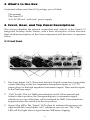
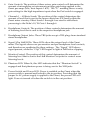
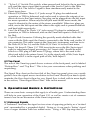
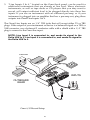
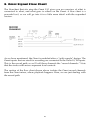
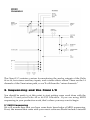
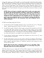
Table of Contents
Introduction . . . . . . . . . . . . . . . . . . . . . . . . . . . . . . . . . . . . . . . . . . . . . . . . . . . . . .2
1. Theory of Operation . . . . . . . . . . . . . . . . . . . . . . . . . . . . . . . . . . . . . . . . . . . . .2
2. Features . . . . . . . . . . . . . . . . . . . . . . . . . . . . . . . . . . . . . . . . . . . . . . . . . . . . . . .3
2.1 Recording Section . . . . . . . . . . . . . . . . . . . . . . . . . . . . . . . . . . . . . . .3
2.2 Mixing Section (all balanced/unbalanced on TRS jacks) . . . . . . . . .3
3. What’s In the Box . . . . . . . . . . . . . . . . . . . . . . . . . . . . . . . . . . . . . . . . . . . . . . .4
4. Front, Rear, and Top Panel Descriptions . . . . . . . . . . . . . . . . . . . . . . . . . . . . . .4
4.1 Front Panel . . . . . . . . . . . . . . . . . . . . . . . . . . . . . . . . . . . . . . . . . . . .4
4.2 Rear Panel . . . . . . . . . . . . . . . . . . . . . . . . . . . . . . . . . . . . . . . . . . . . .6
4.3 Top Panel . . . . . . . . . . . . . . . . . . . . . . . . . . . . . . . . . . . . . . . . . . . . . .7
5. Operational Basics & Definitions . . . . . . . . . . . . . . . . . . . . . . . . . . . . . . . . . . .7
5.1 Balanced Signals . . . . . . . . . . . . . . . . . . . . . . . . . . . . . . . . . . . . . . . .7
5.2 Unbalanced Signals . . . . . . . . . . . . . . . . . . . . . . . . . . . . . . . . . . . . . .8
5.3 Phantom Power . . . . . . . . . . . . . . . . . . . . . . . . . . . . . . . . . . . . . . . . .8
5.4 Sends and Returns . . . . . . . . . . . . . . . . . . . . . . . . . . . . . . . . . . . . . . .8
5.5 Plugs and Jacks . . . . . . . . . . . . . . . . . . . . . . . . . . . . . . . . . . . . . . . . .9
5.6 Balanced Cabling & Connections . . . . . . . . . . . . . . . . . . . . . . . . . . .9
5.7 Unbalalanced Cabling & Connections . . . . . . . . . . . . . . . . . . . . . . .9
5.8 Stereo Input and Insert Cables/Connections . . . . . . . . . . . . . . . . . .10
5.9 Line Levels vs. Mic/Instr Levels . . . . . . . . . . . . . . . . . . . . . . . . . . .10
5.10 Virtual Tracks . . . . . . . . . . . . . . . . . . . . . . . . . . . . . . . . . . . . . . . .10
6. Basic Playback Setup for the Omni I/O . . . . . . . . . . . . . . . . . . . . . . . . . . . . .11
7. Basic Recording Setup for the Omni I/O . . . . . . . . . . . . . . . . . . . . . . . . . . . .14
8. Omni Signal Flow Chart . . . . . . . . . . . . . . . . . . . . . . . . . . . . . . . . . . . . . . . . .16
9. Sequencing and the Omni I/O . . . . . . . . . . . . . . . . . . . . . . . . . . . . . . . . . . . . .17
9.1 MIDI Sequencing . . . . . . . . . . . . . . . . . . . . . . . . . . . . . . . . . . . . . .17
9.2 Setting MIDI Playback Levels . . . . . . . . . . . . . . . . . . . . . . . . . . . .18
10. Recording Audio to the Delta 44 or 66 . . . . . . . . . . . . . . . . . . . . . . . . . . . . .19
10.1 Monitoring the Signals You Are Recording . . . . . . . . . . . . . . . . .20
10.2 Monitoring the Record Inputs Using ASIO or EASI . . . . . . . . . .22
10.3 Setting Record Levels . . . . . . . . . . . . . . . . . . . . . . . . . . . . . . . . . .22
10.4 Record Levels Using the Inserts . . . . . . . . . . . . . . . . . . . . . . . . . .23
10.5 Setting the Audio Track Playback Levels . . . . . . . . . . . . . . . . . . .24
10.6 Adding Effects . . . . . . . . . . . . . . . . . . . . . . . . . . . . . . . . . . . . . . . .25
10.7 Recording Your MIDI Instruments as Audio Tracks . . . . . . . . . . .25
11. Mixing With the Omni . . . . . . . . . . . . . . . . . . . . . . . . . . . . . . . . . . . . . . . . . .26
11.1 Organizing the Audio Tracks for Mixing . . . . . . . . . . . . . . . . . . .27
11.2 Using the Direct Outs 1-4 . . . . . . . . . . . . . . . . . . . . . . . . . . . . . . .27
12. Alternate Omni Setups . . . . . . . . . . . . . . . . . . . . . . . . . . . . . . . . . . . . . . . . .28
12.1 Recording with Four Pre-Amps . . . . . . . . . . . . . . . . . . . . . . . . . .28
12.2 Monitoring While Recording to Four Tracks . . . . . . . . . . . . . . . .28
12.3 Recording Four Line Inputs . . . . . . . . . . . . . . . . . . . . . . . . . . . . .28
12.4 Recording FX . . . . . . . . . . . . . . . . . . . . . . . . . . . . . . . . . . . . . . . .29
12.5 Submixing MIDI Instrument . . . . . . . . . . . . . . . . . . . . . . . . . . . . .29
Limited Lifetime Warranty . . . . . . . . . . . . . . . . . . . . . . . . . . . . . . . . . . . . . . .30
Introduction
Congratulations on your purchase of the Omni I/O Integrated Desktop Audio
Station, designed and manufactured by M Audio. The Omni I/O is a “front
end” companion to the Delta 66 or Delta 44 by M Audio, offering you truly
professional options for both recording to and monitoring from your Delta Series
audio card.
Please read this manual to familiarize yourself with the Omni I/O and its
features, and to understand how you can make the versatility of the Omni I/O
work best for you. Before connecting the Omni I/O, you must install your Delta
44 or Delta 66 card, carefully following the procedure found in the manual for
your Delta card.
1. Theory of Operation
A recording console performs two functions. It routes the signal you are about
to record, providing the ability to pre-amplify and shape that signal before it gets
to the recording device. At the same time, it handles all playback, allowing you
to mix, add an effect, and monitor your recorded signal as well as “virtual” MIDI
keyboard tracks.
The Omni I/O performs these tasks. The Omni, in conjunction with a Delta 44 or
Delta 66 PCI Interface and your PC or Macintosh computer, adds the
functionality of a recording console in a desktop unit. The Omni I/O is modeled
after what is known as a “split console” design, where the recording and
monitoring sections function independently.
Two high quality M Audio Mic/Instrument pre-amps are routed to the Delta’s
analog inputs 1 & 2. The level that you record is controlled by the Omni preamp’s independent gain controls in conjunction with the +4/-10 operating level
that you select in the Delta Control Panel. An insert jack added to the record
path allows you to process the signal with outboard gear, should you choose to.
Line inputs 3 & 4 give you a total of 4 direct analog inputs to the Delta card from
the Omni.
You’ll use your music software and the Delta Control Panel to make routing
selections for recording and monitoring your audio tracks. Audio tracks are
routed from the Delta card to a mixer that is built-in to the Omni, which
combines the four Delta analog outputs with four auxiliary stereo inputs and
one stereo effects return for the equivalent of a 14 channel mixer. One effect send
is provided on each of the Delta output’s mixer channels. The aux inputs can be
used to monitor MIDI instruments as “virtual” tracks, and then route those
instruments to the line inputs for easy recording without repatching.
This ultra-quiet Omni mixer, with extremely wide frequency response, gives you
2
control room outputs and two headphone outputs, all with independent level
controls. A separate “mix” out provides an independent feed to your mixdown
deck. Ultimately, your individual and master volume levels will be controlled by
your music software and/or Delta Monitor Mixer, and therefore can be saved
into the computer’s memory for each recording project.
The Omni I/O takes advantage of computer-based recording and combines it
with proven M Audio pre-amp and mixer technology to bring you an extremely
powerful desktop recording solution. Incorporate your existing gear, or do all of
your sounds and effects right inside the computer. Either way, the Omni I/O
can ultimately handle all of your signal flow from tracking to mixdown.
2. Features
2.1 Recording Section
•
•
•
•
•
2 Mic/Inst plus 2 line level balanced/unbalanced analog inputs to the Delta
44 or Delta 66 soundcard.
The Omni’s two Mic/Inst inputs are equipped with XLR phantom power,
insert I/O jacks, individual gain controls, gain reduction “pad” switch, and
signal/clip indicator LEDs.
Low impedance mic inputs provide 66dB of gain and utilize M Audio’s
critically acclaimed DMP2 pre-amp technology. They are switchable to hiimpedance instrument inputs with 46dB of gain, ideal for electric/acoustic
guitars.
The Omni Mic/Inst pre-amp has a frequency response of 10Hz to 200kHz,
low THD of .0009%, with a dynamic range of 130dB.
Stereo effect return.
2.2 Mixing Section (all balanced/unbalanced on TRS jacks)
•
•
•
•
•
•
•
•
The Delta analog outputs feed the Omni I/O ultra-quiet mixer, with the
addition of 4 stereo aux inputs for MIDI devices and 1 stereo effects return.
The 4 Delta analog outputs can simultaneously be used as independent
balanced/unbalanced direct outs for additional effects sends, alternate mix
outputs, or feeds to a secondary mixer.
Stereo Aux inputs 1 and 2 can be muted in the mixer and re-routed to the
Delta line inputs for easy audio recording of MIDI instruments or other
auxiliary inputs.
Mix out for recording to a mix deck.
Control room outs with independent level control for monitoring.
Two headphone outputs with individual level controls.
One mono effect send per Delta channel.
L/R output signal/clip LEDs.
3
3. What’s In the Box
Contained within your Omni I/O package, you will find:
This manual
The Omni I/O
A 9v AC 500 mA “wall wart” power supply
4. Front, Rear, and Top Panel Descriptions
This section identifies the external connections and controls of the Omni I/O
Integrated Desktop Audio Station, with a basic description of their function.
More detailed descriptions of the Omni components and the basics of operation
follow.
4.1 Front Panel
3
1
2
5
4
6
10
8
7
6
9
11
1.
Mic/Instr Inputs 1 & 2: These dual function Neutrik connectors accept either
a male XLR plug for the low impedance microphone inputs, or 1/4” TS
phone plugs for the high impedance instrument inputs. These are the inputs
to the Omni pre-amps.
2.
“Pad” Switch: This is a 20dB gain reduction switch. When pressed and
locked to the in position, the corresponding mic or instrument signal,
whichever is in use at the time, will be trimmed by 20dB. Gain reduction is
bypassed when this switch is in the out position.
3.
Signal/Clip LEDs: The “Signal” LED, when lit, indicates the presence of a
signal at the Mic/Instr Inputs 1 & 2, whichever one is in use. The “Clip”
LED will first light when a signal reaches 2dB below clipping.
4
4.
Gain Controls: The position of these rotary gain controls will determine the
amount of microphone or instrument pre-amp gain being applied to the
Omni pre-amps (Mic/Instr Inputs 1 & 2). The “U” marking shows a unity
gain setting for the high impedance input when the Pad switch is engaged.
5.
Channels 1 – 4 Effects Sends: The position of this control determines the
amount of level that is sent to the mono effects bus (FX Send) within the
Omni mixer circuitry. Effect Sends 1 through 4 are used to add effects
processing to the Delta’s H/W Outs 1 through 4.
6.
Headphone Controls: The position of these controls determines the amount
of listening level that is sent to the respective headphone jack.
7.
Headphone Output Jacks: These TRS jacks accept a TRS plugs from standard
stereo headphones.
8.
Signal/Clip L&R LEDs: These LEDs show the output level of the Omni
mixer. The signals shown are pre-monitor and pre-headphone level controls,
and therefore are unaffected by these settings. The “Signal” LED shows
signal present, while the “Clip” LED begins to light at 2dB below clipping.
9.
Monitor Control: The position of this control determines the amount of
listening level that is sent to the L&R Monitor Out jacks for control room
listening levels.
10. Phantom LED: When lit, this LED indicates that the “Phantom Switch” is
engaged and that phantom power is being sent to the XLR jacks.
11. Power Switch and Power LED: Power is enabled on the Omni when the
power switch is pressed and locked to the in position. Providing that the
proper 9v AC power supply is applied to the Omni, the power LED will
light. Power is turned off when the switch is in the out position.
5
4.2 Rear Panel
5
2
1
1.
2.
3.
4.
5.
6.
7.
8.
3
4
7
6
9
10
8
7
11
12
13
9v AC Power Jack: This jack accepts a 2.5mm plug from a 9vAC, 500 mA
power supply, included with the Omni. Use only the proper, AC power
supply on the Omni.
Direct Outs 1 – 4: These jacks are connected to the Delta H/W Outs 1
through 4, and bypass the Omni mixer. The 1/4” jacks accept TS plugs for
unbalanced operation, or TRS for balanced.
Phantom Switch: When pressed and locked to the in position, phantom
power is engaged and is sent to the XLR microphone inputs. Phantom
power is switched off when this button is in the out position.
L&R Record (Mix) Outs: The 1/4” jacks accept TS plugs for unbalanced
operation or TRS for balanced. The “Record (Mix) Outs” typically feed a
stereo mixdown deck. These outputs are pre-Monitor Control level, and are
therefore unaffected by changes in “Monitor Control” position.
FX Send: This mono send accepts a TS plug for unbalanced operation, or
TRS for balanced. The send gets its signal from the position of the “Channel
1-4 Effects Send” controls in relation to the signal present at the Delta H/W
Outs 1-4.
L&R Monitor Outs: The 1/4” jacks accept TS plugs for unbalanced operation
or TRS for balanced. These outputs typically feed a monitoring system. They
receive their signal from the stereo bus of the Omni mixer post-Monitor
Level control, and are therefore directly affected by the position of the
“Monitor Control.”
Stereo Aux Ins 1 – 4: These 1/4” jacks accept a TRS plug that is designed to
carry the L&R signals from a stereo source, such as a MIDI keyboard or
other stereo instrument. Typically, a stereo cable with a TRS plug to L&R
mono TS plugs, often called an “insert cable,” will work properly.
“To Ins 1, 2” Switch: This switch, when pressed and locked to the in position,
will send the stereo signal that is present at the Aux In 1 jack to the Delta
H/W In 1 & 2. The Aux In 1 signal is then simultaneously muted to the
Omni stereo buss.
6
9.
10
11.
12.
13.
“To Ins 3, 4” Switch: This switch, when pressed and locked to the in position,
will send the stereo signal that is present at the Aux In 2 jack to the Delta
H/W In 3 & 4. The Aux In 2 signal is then simultaneously muted to the
Omni stereo buss.
Effects (FX) Return: These 1/4” jacks accept TS plugs for unbalanced
operation, or TRS for balanced, and can be used to return the outputs of an
effects device to the Omni mixer. One plug can be plugged into the left input
for mono operation. When only the left jack used in this mono mode, the
signal is directed to the center of the stereo soundfield. When two plugs are
used, one in the left input and the other in the right, each is panned hard left
and hard right respectively.
Line 3 In & Line 4 In: These 1/4” jacks accept TS plugs for unbalanced
operation, or TRS for balanced, and are the Omni line inputs to Delta H/W
Ins 3&4.
15 pin D-sub Connector: Utilizing the specially made shielded cable that
came with the Delta card, the Omni is connected to the Delta card via this 15
pin connector. This cable connects the Omni mic, instrument, and line ins to
the Delta H/W Ins 1-4, and the Delta H/W Outs 1-4 to the Omni mixer.
Insert 1 & Insert 2: These 1/4” TRS insert jacks access the Mic/Instr signal
path for unbalanced signal processing. An “insert cable” should be used,
which is a TRS plug to L&R mono TS plugs, where left is the send to the
effect and right is the return. Insert 1 is in the signal path of Mic/Instr Input
1, while Insert 2 is in the signal path of Mic/Instr Input 2.
4.3 Top Panel
The rear of the Omni top panel shows a mirror of the back panel, and is labeled
“Bottom Row” and “Top Row”. This is for your convenience when patching and
unpatching.
The Signal Flow chart on the front left of the Omni top panel gives you a quick
guide to how the signal moves in relation to the Omni. Should you need a quick
reminder, the flow chart is there for you. Signal flow is dealt with in more depth
in the section, “Omni Signal Flow Chart” later in this manual.
5. Operational Basics & Definitions
There are some basic concepts that apply to all audio gear. Understanding them
will help in your operation of the Omni I/O, as well as create a set of common
terms to use in our discussion of the Omni components.
5.1 Balanced Signals
A “balanced” line runs the signal on two wires of opposing polarity, as a ‘twisted
pair’ surrounded by a grounded shield. Doing so, it can send a ‘hotter’ signal
over a longer distance with less added noise. Using a TRS (tip-ring-sleeve, or
7
stereo) plug on the 1/4” jacks of the Omni (that are designed for unbal/balanced
operation) will give you this balanced line—tip positive, ring negative, and
sleeve ground. Generally, if the Omni outputs connect to a system or device that
accepts a balanced line at +4dB (nominal level) operating level, you should use
TRS plugs on the outputs.
XLR connectors also carry a balanced signal. If your device or monitoring system
accepts an XLR connector, you may need a cable that has 1/4” TRS to male or
female XLR. The mic input of the Omni Mic/Instr Inputs accepts a male XLR,
with a balanced mic cable being female XLR to male XLR.
5.2 Unbalanced Signals
An unbalanced line on the Omni outputs connects to a 1/4” TS (tip positive,
sleeve ground) plug on a shielded cable with a single conductor, and is
appropriate to use when the device you are connecting to accepts a 1/4” TS plug
or an RCA plug. Typically, the signal on unbalanced lines has an operating line
level of –10dB (nominal level), though this varies somewhat.
You may want to consult the user guide of your sound card or sound system if
you’re not sure what type of signal it can accept. If you need to, find a primer on
recording or sound reinforcement to learn more about this and the other subjects
covered in this manual.
5.3. Phantom Power
Unlike dynamic microphones, large diaphragm condenser microphones need to
receive a DC voltage (generally 48v) from an external source before they can
generate an output signal. If the condenser mic doesn’t come with its own
power supply, then phantom power must be applied from the Omni’s Mic/Instr
pre-amps. Pressing the “Phantom” button and engaging phantom power on the
Omni will send the necessary voltage to both of the XLR Mic Inputs.
Phantom power will not affect a dynamic mic adversely, so its not a problem to
have a dynamic mic at the XLR input while phantom power is switched on.
Some ‘ribbon’ microphones (not very common) may be harmed, however, so
check you mic’s documentation.
5.4 Sends and Returns
These are sometimes elusive terms, as they can be used in a variety of ways. A
“send” is an output from a device (such as a mixing console), to another device
(what might be considered ‘outboard’). There is some expectation that the signal
that is sent from the send output is going to “return” to the sending device’s
signal flow. A return is an input to a device.
8
Sends and returns are generally spoken of in terms of the gear that is receiving
the signal. The “effects send,” therefore, is an output from the mixer to the effect.
The effect’s input receives the signal from the “effects send,” and the output of
the effects device returns the signal to the mixer’s input, the “effects return.”
The terms “sends and returns” can apply to other devices, such as a recording
device. The outputs of mixing board are “sent” to a tape deck, for instance, and
the outputs of the tape deck “return” to the mixing desk’s monitor channels for
mixing (often called “tape returns,” though “tape sends” are more often known
as the buss outs).
In this same sense, the analog outputs of the Delta card, i.e., Delta H/W Outs 14, “return” to the Omni mixer. They could properly be called the “Delta returns
to the Omni mixer.”
5.5 Plugs and Jacks
In general, a jack is a female connector, and a plug is a male connector. The jack
is mounted within the hardware device, and the plug exists on the cable ends.
XLR jacks and plugs, however, may be male or female. Usually, the output is
male, and the input is female.
5.6 Balanced Cabling & Connections
The acronym “TRS” stands for Tip-Ring-Sleeve. A 1/4” TRS plug can carry a
balanced mono audio signal over a two-conductor cable with a shield, which
applies to certain TRS jacks on the Omni. This may be considered a standard
1/4” “stereo cable,” though it carries a mono, balanced signal.
If you are using one of the Omni jacks for balanced operation, you will need a
cable with a 1/4” Tip-Ring-Sleeve plug on one end (for the Omni jack), and a
plug on the other end that is appropriate for the device that you are connecting
to. This may be a 1/4” TRS plug, an XLR plug, an 1/8” TRS plug, etc.
5.7 Unbalalanced Cabling & Connections
The acronym “TS” stands for Tip-Sleeve. A 1/4” TS plug is found on what is
commonly referred to as a “guitar cable.” This is a single conductor cable with a
shield, and is generally associated with unbalanced operation.
If you are using one of the Omni jacks for unbalanced operation, you will need a
cable with a 1/4” Tip-Sleeve plug on one end (for the Omni jack), and a plug on
the other end that is appropriate for the device that you are connecting to. This
may be a 1/4” TS plug, an RCA plug, an 1/8” TS plug, etc.
9
5.8 Stereo Input and Insert Cables/Connections
A 1/4” TRS plug can alternately carry an unbalanced stereo audio signal over a
two-conductor cable with a shield, which applies to “Aux In” and the “Insert”
TRS jacks on the Omni. A TRS plug on one end with two mono TS plugs on the
other is in fact a stereo cable, and is sometimes referred to as an “insert cable.”
Keep in mind that the Aux Ins are stereo inputs. A stereo 1/4” TRS plug to two
1/4” mono TS plugs will work for connecting most MIDI sound modules into
the Omni Aux Ins, but you may have to purchase a cable for your particular
needs. This same cable will work for most outboard gear used with the Omni
“Inserts.” See the section, “10.4“ for more on this.
5.9 Line Levels vs. Mic/Instr Levels
Microphones and guitar pickups typically emit a low signal level, requiring a
“pre-amp” such as those found in the Omni Mic/Instr Channels 1 & 2. The
Omni Mic/Instr inputs provide up to 70dB of gain on the XLR mic inputs, and
up to 50dB of gain on the high impedance inputs.
This is enough gain to bring the signal up to the +4 line level at which the Omni
is capable of operating. The Delta card can be set to three line level references, 10dB, “Consumer” (which is –4dB), and +4 dB, which is the default. These
settings can be found in the Delta Control Panel Hardware Settings page, under
“Variable Signal Levels.” Refer to section 10.3 for more information on setting
levels.
Most other signals are already at line level, and can be plugged into Omni Line
Ins 3 & 4. Different equipment, however, runs at different line levels. Check your
device’s documentation to see what line level it runs at, and set the Delta
“Variable Signal Level” to that setting. If you use the Line Ins on the Omni and
find that you’re not getting adequate record levels, you can try lowering the
“Variable Signal Level” setting. You can also experiment with using the Omni
pre-amps, which you might find gives some line level signals a little needed
“punch.”
5.10 Virtual Tracks
Often, instruments such as MIDI gear that is being played by a sequencer, is not
recorded onto the recording device. When not recorded, these MIDI tracks are
referred to as “virtual” tracks. MIDI instruments playing through the Omni Aux
Ins, therefore, are virtual MIDI tracks.
10
6. Basic Playback Setup for the Omni I/O
This section will get you setup for playback and monitoring, as well as for
mixing down when your project is complete (though you may make changes in
your setup at that time). A discussion of the Omni components becomes more
detailed in sections 9 through 11.
Install your Delta card first, according to the Delta installation procedure found
in the Delta 44 or 66 manual. In the step by step instructions that follow, the
items in quotations such as “9v AC Power Jack” relate specifically to numbered
items on the front and back panels of the Omni I/O.
1.
Make sure that the host computer is powered off. Using the shielded 15 pin
to 15 pin cable that came with your Delta card, connect one end of the cable
to the D-sub connector on the Delta card, and the other end to the “15 Pin Dsub Connector” on the back of the Omni I/O.
This cable is a shielded audio cable, and connects the Omni to the four
analog inputs on the Delta card (H/W Inputs 1 through 4). The 15 pin to 15
pin cable also connects the Delta H/W Outs 1 through 4 to the Omni mixer,
and also to the “Omni Direct Outs 1-4.”
2.
Plug the 9v AC power supply into the wall outlet, and connect the 2.5 mm
plug into the “9v AC Power Jack” on the back of the Omni.
3.
Connect the “Monitor Outs” of the Omni to the inputs of your monitoring
system. If your monitoring system’s inputs are unbalanced, use a cable with
a 1/4” Tip-Sleeve plug on the Omni monitor outs, with the appropriate plug,
such as 1/4” TS, RCA, etc., into the monitoring system inputs.
If your monitoring system’s inputs are balanced, use a cable with a 1/4” TipRing-Sleeve plug on the Omni monitor outs, with the appropriate plug, such as
1/4” TRS, XLR, etc., into the monitoring system inputs.
NOTE: A mixer such as the Omni is in itself a pre-amp. This means
that you can connect the Monitor Outs to a power amp or directly
to powered speakers. You can also connect the Monitor Outs to an
integrated amplifier such as a home stereo (though you may not
need as much level from the Omni Monitor Control).
4.
Plug the audio outputs from your MIDI keyboards, sound modules, and
drum machines into each of the four Omni stereo “Aux Ins.” Use a cable that
is a single 1/4” TRS plug to two 1/4” TS plugs, (sometimes referred to as an
“insert cable”), or cabling that is similar while appropriate to your MIDI
modules outputs.
11
NOTE: The Aux Ins add some gain to the signal into the Omni mixer
so that the aux levels blend more easily with the audio tracks
coming from your computer. 17dB of gain is given to the Aux In
signals.
5.
Connect the “Record (Mix) Outs” of the Omni to the analog inputs of your
mixdown deck, such as a cassette tape deck or a DAT. If your mixdown
deck’s inputs are unbalanced, use cable with a 1/4” Tip-Sleeve plug on the
Omni Record Outs, with the appropriate plug, such as 1/4” TS, RCA, etc.,
into the mixdown deck inputs.
If your mixdown deck’s inputs are balanced, use a cable with a 1/4” TipRing-Sleeve plug on the Omni Record (Mix) Outs, with the appropriate plug,
such as 1/4” TRS, XLR, etc., into the mixdown deck inputs.
6.
To connect an effects unit to the Omni I/O, use a 1/4” TS plug if your effects
unit accepts only an unbalanced signal, or a 1/4” TRS plug if your effects
unit accepts balanced signals. Connect your cable from the “FX Send” jack to
the mono input of your effects unit.
You may take the stereo output of your effects unit, and plug into the L&R
“Effects Return.” Once again, use TS for unbalanced and TRS for balanced
operation. If your effect unit has only a mono output, you may plug that mono
output into the Omni FX Return left input only, and that mono signal will
appear panned in the center of the stereo soundfield. Otherwise, left and right
signals will be panned hard left and hard right, respectively.
An effects return is an auxiliary input to a mixer. You can also return effects to
the Aux Ins of the Omni. If you have a mono MIDI instrument, you may want to
use the left input of the effects return to handle this mono signal, and return the
effect (if stereo) to the Aux In.
NOTE: The Effects Return adds some gain to the signal into the
Omni mixer, so that the return levels blend more easily with the
audio tracks coming from your computer. 10dB of gain is given to
the Effects Return signals.
7.
With the Omni “Monitor Level” control in the leftmost position (volume off),
press the power switch and power up the Omni. Next, power up your
computer. With the volume down on your monitoring system, power up
your monitoring system.
You are now setup to monitor and mix recorded audio tracks from your
computer via the Delta card, to add effects to the audio tracks, and to sequence
and mix in your MIDI keyboards. If your music program has a demo file with
audio and MIDI tracks, launch the program and open the file. Make sure that the
MIDI ports are set correctly.
12
8.
Set the audio track’s output ports to Delta Wav Outs 1/2 or 3/4, or Delta
ASIO Outs 1-4 if using the Delta ASIO drivers.
9.
Open the Delta Control Panel to the Patchbay/Router page. Make sure that
H/W Outs 1/2 and 3/4 are set to “WavOut 1/2” and “WavOut 3/4”
(respectively) on the PC, or “SM/ASIO 1/2” and “SM/ASIO 3/4” on the
Mac.
NOTE: The Delta Patchbay/Router, when first installed, is set to
play these software outputs. This setting connects the signal from
the Delta software outputs to the Delta H/W Outs.
10. Once you start playback of your music program, you should begin to see
level indicated on the Output Signal/Clip LEDs, since this level is premonitor control settings. Raise the level on your monitoring system, then
raise the “Monitor Level” control on the Omni until you begin to hear
playback.
So
u
Ca nd
rd
Omni i/O Playback setup
13
7. Basic Recording Setup for the Omni I/O
Now that you’re setup for playback, setting up for recording is the next logical
step. The recording setup is the most likely to change, so we’ll speak in terms of
the types of devices that you will use at the Delta recording inputs.
The Omni is capable of sending four signals to the four analog inputs on the
Delta 44 or Delta 66 cards, via the 15-pin connectors. Each Mic/Instr comprises
one of those paths to the delta card, for a total of two. Line Inputs 3 and 4 make
up the other two paths.
1.
Plug a male XLR cable into “Mic Inputs” 1 and/or 2, when you wish to use
the Omni’s low impedance microphone pre-amps. Generally, if your mic has
an XLR output, use a low impedance, balanced “mic cable” to plug into the
XLR “Mic” input on channel 1 or channel 2.
When using the Mic input on channel 1, the “Instr” input on channel 1 is
disabled until the XLR connector is removed from channel 1. The same goes
for channel 2—when using the Mic input on channel 2, the “Instr” input on
channel 2 is disabled until the XLR connector is removed from channel 2.
If your microphone requires phantom power, press in the “Phantom Power
Switch” on the back panel of the Omni. The “Phantom LED” will light, and
48v of phantom power will be sent to the microphone.
NOTE: Mic Input 1 is connected to, and sends its signal to the Delta
H/W In 1. Mic Input 2 is connected to, and sends its signal to the
Delta H/W In 2.
2.
Plug a 1/4” TS cable into “Instr Inputs” 1 and/or 2, when you wish to use
them as high impedance instrument pre-amp. The Omni instrument inputs
are perfect for electric guitars, acoustic guitars with pick-ups, electric bass, or
any high impedance unbalanced signal that needs a pre-amplification to
bring the signal up to line level.
When using the instrument input on channel 1, the “Mic” input on channel 1
is disabled until the 1/4” TS plug is removed from channel 1. The same goes
for channel 2—when using the instrument input on channel 2, the “Mic”
input on channel 2 is disabled until the 1/4” TS plug is removed from
channel 2.
NOTE: Instr Input 1 is connected to, and sends its signal to the
Delta H/W In 1. Instr Input 2 is connected to, and sends its signal to
the Delta H/W In 2.
14
3.
“Line Inputs 3 & 4,” located on the Omni back panel, can be used for
additional instruments that are already at line level. Many electronic
instruments, as well as tape decks or CD players that you may want to
record, will output sufficient level to be plugged directly into these line
inputs. If you use an instrument with an outboard pre-amp, or if your
instrument is plugged into an amplifier that has a pre-amp out, plug those
outputs into Omni Line Inputs 3 & 4.
The Omni Line Inputs are on 1/4” TRS jacks that will accept either TS or TRS
plugs. If the output of your instrument or device is a balanced signal on a TRS or
XLR connector, use a balanced 2 conductor cable with a shield with a 1/4” TRS
plug to connect to the Omni line input.
NOTE: Line Input 3 is connected to, and sends its signal to the
Delta H/W In 3. Line Input 4 is connected to, and sends its signal to
the Delta H/W In 4.
IC
R
M
LA
Y
E
OR
R
E
S
S
O
R
P
P DY
R N
O A
C M
E IC
S S
S
O
R
P
R
E
D
M
P
2
COMPUTER
C
O
M
P
INPUTS
OUTBOARD
GEAR
Guitar
Mic
Omni i/O Record Setup
15
8. Omni Signal Flow Chart
The flowchart that sits atop the Omni I/O gives you an overview of what is
connected to what, and what goes to where on the Omni. A flow chart is a
powerful tool, so we will go into it in a little more detail with the expanded
version.
As we have mentioned, the Omni is modeled after a “split console” design. The
Omni inputs that are used for recording are connected to the Delta H/W inputs.
This is the record path, so we’ll call those channels the “record channels.” Note
that the circles with arrows represent level controls.
The section of the flow chart shown above isolates the Omni record channels
from the Omni mixer, where playback happens. Here, we are just dealing with
the record path.
16
The Omni I/O contains a mixer for monitoring the analog outputs of the Delta
44 or 66, four stereo auxiliary inputs, and a stereo effects return. These are the 14
channels of the Omni mixer path, so we’ll call them the “mixer channels.”
9. Sequencing and the Omni I/O
You should be ready to at this point to start getting some work done with the
Omni I/O and your Delta 44 or 66 PCI Interface. If you are using MIDI
sequencing in your production work, that’s where you may want to begin.
9.1 MIDI Sequencing
We will assume here that you have some basic knowledge of MIDI sequencing.
If not, the manual that came with your music software should include a tutorial
17
to get you up and running. We also assume that you have installed a MIDI
interface into your computer, and that this basic MIDI setup has already been
established.
The Omni provides you with four “Aux Ins” for monitoring your MIDI
keyboards while you are sequencing and creating MIDI tracks. The auxiliary
inputs can be used for different purposes, but monitoring MIDI keyboards,
samplers, and drum machines is their primary intention. If you use only the
MIDI synthesizer that is part of your computer’s sound card (like a Dman PCI, a
Sound Blaster, or Yamaha OPL), we suggest taking the audio output of the
sound card and plugging it into the Omni Aux Input (using the proper adapter
cable).
We chose the stereo 1/4” TRS jack so that more Aux Ins would fit on the Omni.
Many people use up to four MIDI devices, so more inputs is preferable, though
it does require a special cable. If you need additional inputs, a line mixer can
combine several devices to one of the Omni stereo auxiliary inputs.
If you’ve followed the basic playback setup in section 6, you are ready to
monitor your MIDI instruments and therefore ready to start sequencing using
your MIDI sequencing software. Even if you wish to begin your recording
project with some live audio tracks, you may want to establish a MIDI
metronome “click track” as a timing reference. This can help, especially if you
want to record MIDI tracks later.
9.2 Setting MIDI Playback Levels
Playback levels of your MIDI tracks will be controlled by your sequencing
software. We suggest setting the output control on each of your MIDI sound
modules to the maximum setting (if they seem noisy at that setting while no
MIDI is playing, choose 12 o’clock or 3 o’clock). Then, set the playback level of
your MIDI track by adjusting the MIDI volume of that particular patch being
used (this can be done within the sound module or on the sequencer MIDI
track), and/or by adjusting the MIDI velocity setting on the MIDI track in the
sequencer.
By setting the MIDI playback level on each individual MIDI track, that setting is
saved with your software’s song file. By leaving the MIDI sound modules on
their maximum setting, or by leaving them on one particular setting
(like 9 o’clock or 12 o’clock), the MIDI levels saved in your software will give
you “instant recall” of consistent playback levels.
18
10. Recording Audio to the Delta 44 or 66
Take some time to read the Delta manual that came with your Delta card.
Recording audio tracks requires a proper record setup, but setup for monitoring
those signals while recording is equally important.
Having read the basic recording setup in section 7 of this manual, you
understand that Omni Mic/Instr Channel 1 is connected to the Delta H/W
(hardware) In1. Omni Mic/Instr Channel 2 is connected to the Delta H/W
(hardware) In 2, and Omni Line Ins 3 & 4 are connected to Delta H/W Ins 3 & 4
respectively. This is the Omni recording section, and these are the “record
channels.”
Below, for your convenience, we’ve created a chart describing what “source”
you should select within your music software for your respective Omni inputs.
Next, you’ll want to set up the way you monitor the signals you are recording,
then set up the gain structure for your recording levels.
OMNI Input:
Mic In1
Instr In 1
Mic In 2
Instr In 2
Line In 3
Line In 4
Set Input "SOURCE" To:
Left PCM In 1/2 Delta
Left PCM In 1/2 Delta
Right PCM In 1/2 Delta
Right PCM In 1/2 Delta
Left PCM In 3/4 Delta
Right PCM In 3/4 Delta
Delta ASIO:
ASIO In 1
ASIO In 1
ASIO In 2
ASIO In 2
ASIO In 3
ASIO In 4
M Audio Delta EASI:
Input 1
Input 1
Input 2
Input 2
Input 3
Input 4
Aux In 1 to "Ins 1,2"
Left PCM In 1/2 Delta
Right PCM In 1/2 Delta
Left PCM In 3/4 Delta
Right PCM In 3/4 Delta
ASIO In 1
ASIO In 2
ASIO In 3
ASIO In 4
Input 1
Input 2
Input 3
Input 4
Aux In 2 to "Ins 3,4"
Aux In 1 to "Ins 1,2"
Aux In 2 to "Ins 3,4"
Software W/ Stereo Ins
Stereo PCM In 1/2 Delta
Stereo PCM In 3/4 Delta
M Audio Delta EASI:
Input 1/2
Input 3/4
Recording software will vary, but once you’ve set up your levels, recording them
is fairly basic. Recording is also covered extensively in your Delta manual, and
there should also be a tutorial in your software’s manual.
With the gain controls on the Omni turned down, plug a microphone or an
instrument (such as electric or acoustic guitar) into Mic/Instr Channel 1 and/or
Channel 2. Or, plug a line level device such as a CD player or additional
mic/instrument pre-amps into Line Ins 3 & 4.
19
1. Launch your music software, then select a track for recording.
2. Choose the proper Delta input as the source for that track.
3. Enable the track for recording.
10.1 Monitoring the Signals You Are Recording
We’ve spoken about listening to the playback of recorded audio files while the
Delta Patchbay/Router is set to the “software” outputs. Only certain music
software allows you to use that setting to monitor the signals you are recording.
See the next section, 10.2, for more info on monitoring the record channels using
the software ouputs (Patchbay /Router “WavOut” (PC) or “SM/ASIO Out”
(Mac) settings), which applies when using the Delta ASIO or EASI drivers.
The Patchbay/Router in the Delta Control Panel allows you to monitor the
record inputs (Delta H/W Ins) in two other fashions. You may select the H/W
Ins as your monitoring source for the H/W Outs. Or, you may select the Monitor
Mixer as the source in the Patchbay/Router page, and then bring up and unmute
the fader(s) assigned to “H/W In.” Here are some suggestions for monitoring
setups along those lines. Once you have chosen your setup, refer to section 10.3,
“Setting Record Levels.”
NOTE: The Omni I/O runs at a +4dB line level. We suggest leaving
the Variable Signal Level in the Delta panel’s Hardware Settings
page to +4 for the Delta Outs. If this setting causes your sound
system or mix deck to distort, try a lower setting.
A. When recording using the Mic/Instr Ins:
1.
In the Delta panel’s Patchbay/Router page, set H/W Out 1/2 to “Monitor
Mixer” (make sure that H/W Out 3/4 is set to “WavOut 3/4”).
2.
In the Delta panel’s Monitor Mixer page, unmute the channels for H/W In
1/2. Raise the faders to all the way to full level (this setting will not affect
record levels). You will later use these faders to adjust listening level after
“Setting Record Levels” in section 10.3. Pan each channel as desired (if these
are mono instruments, you might want to pan them to the center).
3.
In the Monitor Mixer page, unmute the channels for H/W Out 1/2, and
raise the faders to full level.
4.
Set the audio track’s source in your music software according to the chart in
section 10. Set the same track’s output ports to WavOut Delta 1/2 (or ASIO
Out 1 and 2), and pan them in a fashion similar to the inputs in your
Monitor Mixer page.
20
Using this setup, you will be able to record from the Omni Mic/Instr inputs,
monitoring the H/W inputs while you record, and then monitor the tracks once
they are recorded. All of these signals will enter the Omni mixer on channels 1
and 2. You can add effects (see section 10.6) to these channels while you are
recording (the effect will not be recorded). Playing back the recorded tracks on
these same two Omni channels will give you the same amount of effects on each
channel.
NOTE: Once you have recorded some basic tracks, you may want
to switch the software output setting in your music software to
WavOut Delta 3/4 (or ASIO 3 and 4). These will then enter the Omni
mixer on channels 3 and 4, which allows you to add effect and set
playback levels independent of the signals you are recording. If
you’ve set your playback levels in the software (setting the Monitor
Mixer H/W Out levels to the maximum), then your playback levels
will be identical.
B. When recording using the Line Ins:
1.
In the Delta panel’s Patchbay/Router page, set H/W Out 1/2 to “Monitor
Mixer” (make sure that H/W Out 3/4 is set to “WavOut 3/4”).
2.
In the Delta panel’s Monitor Mixer page, unmute the channels for H/W In
3/4. Raise the faders all the way to full level (this setting will not affect
record levels). You will later use these faders to adjust listening level after
“Setting Record Levels” in section 10.3. Pan each channel as desired (if these
are mono instruments, you might want to pan them to the center).
3.
In the Monitor Mixer page, unmute the channels for H/W Out 1/2, and
raise the faders to full level.
4.
Set the audio track’s source in your music software according to the chart in
section 10. Set the same track’s output ports to WavOut Delta 1/2 (or ASIO
Out 1 and 2), and pan them in a fashion similar to the inputs in your
Monitor Mixer page.
NOTE: Most of the time, recording is done in an “overdub” style.
See section 12.2 for more information on recording using the
Mic/Instr and Line Ins at the same time.
With the Omni, keep in mind that all four Delta outputs are connected to the
inputs of the Omni mixer. That means, that if you have a signal at the Delta
H/W Outs 3/4, and you also have the H/W Out 3/4 signal present (faders up)
in the Delta panel “Monitor Mixer” (which is output to Delta H/W Outs 1/2),
21
then this signal will appear on the Omni mixer channels 1 & 2 as well as mixer
channels 3 & 4. Generally, this is not a desirable scenario, and setup B is
designed to prevent this.
10.2 Monitoring the Record Inputs Using ASIO or EASI
If your music software allows you to monitor the software outputs of the
program, such as those programs using the ASIO or EASI drivers, then the
default Patchbay/Router setting (WavOut on the PC, or SM/ASIO Out on the
Mac) will work for monitoring the audio signal you are recording. Check your
software manual to see if it uses ASIO or EASI drivers, then make that selection
in the audio setup page. On the PC, the Delta ASIO drivers load automatically.
On the Mac, you must drag the proper ASIO driver into your software’s ASIO
folder (these instructions are included in your Delta installation instructions).
The Delta H/W (hardware) inputs are getting their signal from the outputs of
the Omni’s recording path (see “Omni Flow Chart), as we have already stated.
We still need to designate how we are going to monitor (hear) those signals that
we are trying to record. Again, if your software allows you to monitor the Delta
H/W inputs through the software, as most programs that use ASIO (or EASI) do,
you will also need to select that type of monitoring within the software’s audio
setup page. Most often, this is called “tape type monitoring” as it is similar to an
analog tape deck that allows you to monitor the inputs through the machine.
This is why, when you monitor through the software, that the Patchbay/Router
can be set to monitor the software outputs.
10.3 Setting Record Levels
There are a number of possible places in the signal flow that allow for adjusting of “gain,”
or the amount of level that is assigned. These are called the “gain stages.”
The Omni provides a gain adjustment control on Mic/Inst Channels 1 & 2. The
Delta 44 or 66 allows you to set the operating line level, -10, Consumer, and +4.
These are the gain stages that are used to set up your record levels using the
Omni and the Delta card. If you plan to use the Inserts on Omni channels 1 & 2,
this can add gain stages to the record setup (see section 10.4 for more on using
the inserts).
To set record levels for the Omni Mic/Instr channels:
1.
Open the Delta Control Panel to the Hardware Settings page. In the
“Variable Signal Levels” section, set the level to +4 for the Delta inputs you
will be using. The Omni operates at +4, though it may be advantageous at
times to use a lower setting (Consumer or –10).
2.
Start with the channel 1 & 2 gain controls all of the way to the left. Choose
one of the monitoring setups described in section 10.1 or 10.2.
22
3.
Start to raise the Omni gain control while testing your microphone or guitar.
If you are using an instrument with volume controls, start with it on the
highest setting, then play to test the level. Raise the Omni gain control to
between 9 o’clock and 12 o’clock, or until you see the green signal LED start
to light.
4.
Continue to test the mic or instrument, making sure that the clip LED never
stays lit for too long. If the clip LED lights easily with the gain control set to
9 o’clock or less, try pressing the “Pad” switch (this will trim the input signal
by 20dB).
5.
Bring up the level meters in the Delta panel Monitor Mixer. The signal level
that you see at the H/W Ins will ultimately be your record levels, as they
should be identical to the level meters in your software. Adjust the Omni
gain controls until the signal nearly reaches the red area. It should never hit
the top of the meter.
NOTE: If you seem to have to turn the Omni gain up past 2 o’clock
and still do not register adequate levels in the Delta Monitor Mixer,
go to the Delta panel Hardware Setting page. Adjust the Variable
Signal Level on your particular input to a lower setting (Consumer
or –10) in order to reduce headroom.
Once you have set the record levels, you may begin to adjust the listening or
monitoring levels for those channels. If you are using the Delta Monitor Mixer,
setting the fader level in the Delta Monitor Mixer page will affect only the
monitoring levels, and will not affect record levels. This is also true of the faders
in your software if you are monitoring through your software. Changing the
monitor level will not affect the record level.
To set record levels for the Omni Line Ins:
Since there are no gain controls for the line inputs, you will need to adjust the
output control on the device that you are recording. If your device runs at a line
level other than +4, set the Variable Signal Level in the Delta panel to
“Consumer” or –10dB. If you are getting low record levels with the device
output level turned up, lower the Variable Signal Level in the Delta panel. Or, if
turning up the output levels introduces noise, lower the output level and then
lower the Variable Signal Level in the Delta panel.
10.4 Record Levels Using the Inserts
“Inserts” give the user an insertion point in a signal flow for adding signal
processing. Each Omni Insert provides an unbalanced output from the record
channel, then brings that unbalanced signal back into the record channel, via a
23
1/4” TRS connection. This now processed signal is what is sent to the Delta
H/W Ins, which are the record inputs to the Delta card.
This type of insertion point is most often used for dynamics processors such as
compressors or expanders (noise gates), or for other outboard gear such as an
equalizer (EQ). Since an insert is often found on a patchbay, using an insert to
add a processor to the signal flow is sometimes called “patching-in.” We will
refer to these patch points as “insert out” and “insert in.”
Use the left side of the cable for the Omni ‘insert out’ point. This will then plug
into the input of your outboard device. The right side of the cable is your ‘insert
in’. Plug it into the output of your outboard device. This piece of outboard gear
is now part of the signal flow, and the recorded signal will include this
processing. Your insert cable will either be marked “left” and “right,” or
designate the right side of the stereo signal by being colored or marked in red.
Outboard gear such as dynamics processors will have controls and settings that
will vary from one device to another. Therefore, we can only speak in general
terms and suggest a way to go about adjusting these gain stages. With the
processing controls set to a neutral setting, or bypassed:
1.
If there is an output setting on the outboard device, set it to 0dB, or unity
gain. This way, the device is not adding or attenuating the original signal.
2.
Set the input level on the device, trying to match the level of the signal
(according to how it shows up in the Delta mixer or the music software).
3.
Adjust processing controls, such as threshold and ratio, toward the desired
effect. Adjust the output level on the outboard device as needed, finally finetuning all gain stage levels.
See section 10.6 for “Adding Effects.” The Omni Inserts can also be used to
‘patch in’ effects devices, however, effects are not usually added in this way. It is
possible to use the ‘insert out’ point, but not use the ‘insert in’, and instead bring
the output of the effect back into the Omni on another channel. See the section
“Alternate Omni Setups” for more on this.
10.5 Setting the Audio Track Playback Levels
Once you have recorded an audio track in your music software, you may want
to adjust the playback levels for these audio tracks. These playback levels will be
controlled by your music software.
The Delta H/W outputs 1-4 are connected directly to the Omni mixer. These Omni
mixer inputs are what is known as “unity gain” inputs. Unity gain means what goes
in is what comes out—no gain is added and none is attenuated (reduced).
24
Therefore, the volume level on each individual audio track recorded in your
music software will control the playback level that enters the Omni mixer. Your
music software may also have a mixer panel to control playback levels. Either
will work fine, as generally, the MIDI volume level that you set on an individual
track will be reflected in the software’s mixer panel.
The audio track’s MIDI velocity setting will also affect the playback level. You
can enter a positive or negative value. If you enter in a positive value, it is
possible to cause clipping (distortion from to much level), so pay attention to
playback levels if this is the case.
The advantage of this system is that once you have set your playback levels for
audio and MIDI, these settings are saved when the song file is saved. These
saved settings can be recalled when the song file is opened again.
10.6 Adding Effects
One mono effects send, and one stereo effects return are provided on the Omni
mixer. Individual send levels on each of the four Omni mixer channels that are
the Delta H/W outputs, allow you to add effects process to your audio track
within the Omni mixer.
Once you have followed the procedure in section 6 for hooking up your effects
unit, you will be ready to apply send level on each of the Omni mixer channels.
1.
Start playback of your music software. If you have audio playing out of the
Delta H/W Out 1, increase the send level on Omni “Channels 1-4 Effects
Sends.”
2.
You should begin to see level on the input of your effects unit (if it has a
level indicator), and also hear the effect as the processed signal returns to the
“Effects Return.” Adjust the input level of your effect until a moderate input
level is reached, with a normal Omni send level of between 9 o’clock and 12
o’clock.
3.
Adjust the effect’s output level until a desirable amount of effects level is
achieved.
NOTE: Some effects units allow you to create a mix balance
between the signal going to the effect, and the effect itself. In this
type of effects setup, always run the effect at 100%, with none of
the original signal added.
10.7 Recording Your MIDI Instruments as Audio Tracks
At a certain point, you may wish to record your MIDI instruments as audio
tracks. If you have been monitoring your MIDI instruments using the Omni Aux
Ins, the Omni offers a convenient way to record those instruments.
25
1.
Next to Aux In 1 is a switch labeled “To Ins 1, 2.” Pressing in and engaging
this switch, will a) take the signal present at the Aux In1 out of the stereo
buss of the Omni mixer, and b) send that same signal to the Delta H/W Ins 1
& 2.
2.
Next to Aux In 2 is a switch labeled “To Ins 3, 4.” Pressing in and engaging
this switch, will a) take the signal present at the Aux In 2 out of the stereo
buss of the Omni mixer, and b) send that same signal to the Delta H/W Ins
3 & 4.
Remember that the Aux Ins are stereo inputs. They carry the left and right
signals from a stereo device (such as your MIDI sound modules). Therefore, Aux
In 1 feeds Line Ins 1 & 2 of the Omni (left and right respectively), which in turn
feed the Delta H/W Ins 1 & 2. Aux In 2 feeds Line Ins 3 & 4 of the Omni (left and
right respectively), which in turn feed the Delta H/W Ins 3 & 4.
Also, since the Omni mixer channels for the Aux Ins gives a boost in level, you
will experience a drop in listening level when you engage the “To Ins 1, 2”
switch. What is important at this point is to establish an optimal level for
recording the MIDI tracks, and then to set the playback levels once the track is
recorded.
NOTE: “Aux to Line In” switches are only provided for Aux Ins 1 & 2.
Aux Ins 3 & 4 can not be routed to the Omni Line Ins in this fashion.
11. Mixing With the Omni
Once you have sequenced your MIDI tracks and recorded all of your audio
tracks, you are ready to mix your project with the Omni. There are two ways that
we will suggest that you go about it.
A. Using the Omni “Record Outs,” record to your mixdown deck with your
MIDI sound modules plugged into the Omni Aux Ins as “virtual tracks” (tracks
not recorded as audio tracks). The recorded audio tracks will also play through
the Omni mixer. You may use the effect send on the Omni as well as add effects
in your music software.
This setup is the same as the basic playback setup described in section 6. You can use
it to run off “rough mixes” as your project develops, as well as for your final mix.
While mixing, you can use the Omni Direct Outs as additional effects send on
individual Delta H/W Outs. This is covered in section 11.2.
B. You can choose to record all of your sequenced MIDI sound modules into
your music software as audio tracks. Once you have done this, your music
software may allow you to add effects to the individual tracks (if the software
and your system resources allow it).
26
You can still mix through the Omni, adding effects using the Channel 1-4 Effects
Send, and also using the Direct Outs. We will describe using the Direct Outs in
the section 11.2, “Using the Direct Outs 1-4.”
11.1 Organizing the Audio Tracks for Mixing
There are a number of ways to setup the audio tracks for mixing. Here are a
couple of suggestions.
Let’s say that you’ve recorded two live rhythm guitars, four background vocals, lead
vocal and lead guitar. The Delta has four software outputs, arranged in two stereo
pairs. These pairs are 1/2, and 3/4. The Delta Patchbay/Router should be set to the
software outputs for this example (WavOut on PC, SM/ASIO on the Mac).
In your music software, set your rhythm guitars and background vocals to software
outs 3/4. Pan the guitars, and set the background vocals to varied pan positions and
all of your playback levels within your music software. Add effects by increasing the
level control on Omni channels 3 and 4 effects sends.
Software outs 1/2 are now left for your lead vocal and lead guitar. This setup allows
you to treat the lead instruments separately. Most likely, you will pan the lead vocal
in the center, and possibly the lead guitar also panned center. Add the amount of
effect you desire on the lead vocal, and give the lead guitar its own amount of effects,
by increasing the level control on Omni channels 1 and 2 effects sends.
Providing that you have an Aux In available, this setup also allows you to patch
in a single effect for each of these lead instruments. Refer to the next section,
11.2, for more information on how this can be done.
11.2 Using the Direct Outs 1-4
The Direct Outs 1-4 are directly connected to the Delta H/W Outs 1-4, and are
unaffected by the Omni mixer. They can be used to send the signal of a single
recorded audio track to an additional effects units. Mostly, you’ll want to do this
during mixdown. You will also need to have Aux Ins available to return the
effects to the Omni, or a submixer for effect returns with its stereo out connected
to the Omni FX Return.
1.
If you have an audio track set to output to the Delta H/W Out 1, for
example, connect Direct Out 1 to the input of your effects unit.
2.
Take the output of the effects unit, and “return” it to one of the Omni Aux
Ins. Control the listening level of the effect by adjusting the input and output
controls on the effects unit itself.
27
12. Alternate Omni Setups
These are some advanced techniques. Once you master the Omni basics, you
may want to try some of these variations.
12.1 Recording with Four Pre-Amps
The Omni provides you with 2 pre-amp channels, Mic/Instr Channel 1, and
Mic/Instr Channel 2. If you need to use two more pre-amps, you may connect
the line outputs of two pre-amp channels to Omni Line Ins 3 & 4.
The M Audio DMP-2 is a perfect companion to the Omni pre-amps, and will
give you the same high quality sound. If you already own a mixer with preamps built-in, you can take a direct, buss, or insert output from the pre-amp
channels, and connect this to Omni Line Ins 3 & 4.
12.2 Monitoring While Recording to Four Tracks
If you are using the Delta Monitor Mixer to monitor your inputs while recording
(as opposed to monitoring through a program using the ASIO or EASI drivers),
then follow this monitoring scenario when recording four tracks (or more than
two inputs to more than two tracks).
1.
In your music software, set the four Omni record channel inputs to record to
Delta Left and Right PCM Ins 1/2 and 3/4, respectively. Set them to output
to Delta WavOuts 1/2 and 3/4.
2.
In the Delta Patchbay/Router page, set H/W Outs 1/2 to “Monitor Mixer”
as the source. Set H/W Out 3/4 to “H/W In 3/4” as the source.
3.
In the Delta Monitor Mixer page, unmute and raise the faders for H/W In
1/2, but not H/W In 3/4. Unmute and raise the faders for H/W Out 1/2,
and also for H/W Out 3/4.
This setup will prevent you from hearing H/W Outs 3/4 both from Omni
Channels 1 &2, and from 3 & 4, while recording and playing back. You will hear
H/W In 3/4 from H/W Out 3/4 while recording, and from H/W Out 1/2
(Monitor Mixer) when playing back.
12.3 Recording Four Line Inputs
The Omni is set up with 2 mic/instrument inputs that are connected to the Omni pre-amp
(Mic/Inst Channels 1 & 2), and 2 line inputs connected directly to the Delta H/W Ins (Line
Ins 3 & 4).
If you wish, at some time, to record four devices to line inputs, there are three choices. You
can use the Aux In 1, and press in the “To Ins 1, 2” switch. This will give you 2 unbalanced
line inputs to the Delta H/W Ins 1 & 2. Alternately, you could use the “Inserts” on channels
28
1 & 2, by plugging in only to the insert in (the red, or right side of the insert cable). This will
break the signal flow of the pre-amps to the inserts, allowing you to have 2 unbalanced line
inputs to the Delta H/W Ins 1 & 2. Pressing in the “To Ins 1, 2” switch will disconnect the
Mic/Instr channels, however, so you must chose one or the other.
The third method is to use the Instr In on Channels 1 & 2 of the Omni pre-amp. The “U”
marking shows a unity gain setting for the high impedance input when the Pad switch is
engaged. This will give you the equivalent, in level, of a line level input, with the option of
adjusting the gain. Understand, however, that this does send the signal through the Omni
pre-amp electronics.
12.4 Recording FX
There are occasions where you might want to record the outboard effects along with the
mic or instrument currently being recorded. You may also want to record effects for tracks
already recorded. Doing so will allow you to choose another effect, or “free-up” the effects
device for another vocal or instrument (assuming that you have a limited number of effects
units). In both cases, we recommend recording the effects onto their own audio tracks in
your software, allowing you to blend them with the principle track as you please. Also,
recording to the same track could cause a feedback loop if you’re recording effects at the
same time you’re recording the instrument or mic.
1.
2.
3.
Assume that you have a vocal mic plugged into Mic/Instr Channel 1, recording onto
“Left PCM In 1 Delta.” The software outputs are set to Delta WavOut 1/2, and
according to monitor setup A(section 10.1), this is being sent to Delta H/W Out 1.
Use Omni Direct Out 1 as your effect send. Connect it to the input of your effects unit.
Take the outputs of your effects unit, and “return” them to Omni Line Ins 3 & 4. Set
two tracks of your music software to record “Left and Right PCM 3/4 Delta” (or one
track to “Stereo PCM” if your software records stereo tracks). Use the monitoring
scenario described in section 12.2.
You can use the “Effects Send” in a similar way, but return the effects in the fashion
described in step 3. The Effects Send will give you control over the levels going to the effect
unit. The ‘insert out’ point on Mic/Instr Channels 1 & 2 will also give you an effects send
(to be returned to Omni Line Ins), but only for instruments on that record path while you
are recording them.
12.5 Submixing MIDI Instruments
If you have more than four stereo MIDI instruments or sound modules (the number of
Aux Ins), then you might want to connect the MIDI gear to a mixer, and then connect the
stereo output of the mixer to an Omni Aux In. This is called “submixing.”
Also, you can use this “submix” technique to free-up Aux Ins, or to submix
effects returns. If you are following the “Using Direct Outs 1-4” for adding other
effects units while mixing, this will come in handy if you are running your MIDI
instruments as “virtual tracks.”
29
Limited Lifetime Warranty
M Audio warrants that this product is free of defects in materials and workmanship under
normal use so long as the product is: owned by the original purchaser; the original
purchaser has proof of purchase from an authorized M Audio dealer; and the purchaser
has registered his/her ownership of the product by sending in the completed warranty
card.
This warranty explicitly excludes power supplies and included cables which may become
defective as a result of normal wear and tear.
In the event that M Audio receives written notice of defects in materials or workmanship
from such an original purchaser, M Audio will either replace the product, repair the
product, or refund the purchase price at its option. In the event any repair is required,
shipment to and from M Audio and a nominal handling charge shall be born by the
purchaser. In the event that repair is required, a Return Authorization number must be
obtained from M Audio. After this number is obtained, the unit should be shipped back
to M Audio in a protective package with a description of the problem and the Return
Authorization clearly written on the package.
In the event that M Aaudio determines that the product requires repair because of user
misuse or regular wear, it will assess a fair repair or replacement fee. The customer will
have the option to pay this fee and have the unit repaired and returned, or not pay this fee
and have the unit returned unrepaired.
The remedy for breach of this limited warranty shall not include any other damages.
M Audio will not be liable for consequential, special, indirect, or similar damages or
claims including loss of profit or any other commercial damage, even if its agents have
been advised of the possibility of such damages, and in no event will M Audio’s liability
for any damages to the purchaser or any other person exceed the price paid for the
product, regardless of any form of the claim. M Audio specifically disclaims all other
warranties, expressed or implied. Specifically, M Audio makes no warranty that the
product is fit for any particular purpose.
This warranty shall be construed, interpreted, and governed by the laws of the state of
California. If any provision of this warranty is found void, invalid or unenforceable, it
will not affect the validity of the balance of the warranty, which shall remain valid and
enforceable according to its terms. In the event any remedy hereunder is determined to
have failed of its essential purpose, all limitations of liability and exclusion of damages
set forth herein shall remain in full force and effect.
30