1
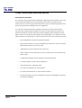
ASPECT TA-890 SYSTEM
USER MANUAL
Turbosound Ltd.
Star Road, Partridge Green
West Sussex RH13 8RY United Kingdom
Tel: +44 (0)1403 711447 Fax: +44 (0)1403 710155
web: www.turbosound.com
Issue 1.3 © Turbosound Ltd, October 2005
user manual
TA-890
Contents
EC Declaration of Conformity........................................................................................................................ 6
Introduction .................................................................................................................................................... 7
Turbosound Aspect System Concepts ..................................................................................................... 7
The Turbosound Polyhorn™..................................................................................................................... 7
Aspect TA-890 Turnkey System Concept...................................................................................................... 9
The Loudspeaker Management System (LMS) Concept....................................................................... 10
LMS-D24, LMS-D26 and LMS-D6 Loudspeaker Management Systems............................................... 10
Amplifier Racks........................................................................................................................................ 10
Power Amplifiers..................................................................................................................................... 10
Digital Controllers ................................................................................................................................... 11
Aspect Loudspeaker Components.......................................................................................................... 11
TA-890L Low Frequency Enclosure ........................................................................................................ 11
TSW-218 Subwoofer ............................................................................................................................... 12
TA-890H Mid-high Enclosure.................................................................................................................. 12
Transportation ......................................................................................................................................... 14
Aspect Flying Systems ............................................................................................................................ 15
Flying and Stacking...................................................................................................................................... 16
Overview.................................................................................................................................................. 16
GigMate™ Acoustic Simulation .................................................................................................................. 17
TA-890 user manual
Page 2
user manual
TA-890
Setting up a Venue - Overview............................................................................................................... 17
Running Turbosound GigMate™ / EASE Focus for the first time: ....................................................... 18
Designing a system ................................................................................................................................. 20
Changing the system .............................................................................................................................. 23
Safety Notes on Rigging ......................................................................................................................... 25
Sample Certificate of Load Test ............................................................................................................. 26
Flying Hardware ...................................................................................................................................... 27
Wide and Narrow Flybar Settings .......................................................................................................... 27
Figure 1. Single A-System Flybar FB-890/1A ......................................................................................... 28
Figure 2. Double A-System Flybar FB-890/2A........................................................................................ 29
Figue 3. Triple ‘A’ System Flybar FB-890A/3W ...................................................................................... 30
FC-890 Flying Chains............................................................................................................................... 31
TS-890 Tilting Straps............................................................................................................................... 31
Three-wide hang using MB-890, EB-890, FB-890/2A and FB-890/1A .................................................... 32
Four-wide hang using MB-890 and FB-890/2A ...................................................................................... 33
Integral Flying Hardware ........................................................................................................................ 34
‘A’ System Flygear .................................................................................................................................. 34
1. Drop Link.............................................................................................................................................. 35
2. Swing Latch ......................................................................................................................................... 35
Connecting Flying Chains to the Cabinet............................................................................................... 35
Figure 1 – insert cabinet link
Figure 2 – release swing latch............................................................. 35
Connecting Cabinets - ‘A’ System .......................................................................................................... 35
Setting Vertical Angles – ‘A’ System...................................................................................................... 36
Attaching the Tilt Straps ......................................................................................................................... 37
Turbobass Directivity .............................................................................................................................. 38
Bass Enclosure arraying.......................................................................................................................... 38
Aiming - directivity of the stack.............................................................................................................. 38
The typical Left to Right problem........................................................................................................... 40
Creating Directional Bass arrays: ........................................................................................................... 41
Bass in a line:........................................................................................................................................... 41
Fanned bass............................................................................................................................................. 42
Bessel Array............................................................................................................................................. 43
General observations of long lines of bass ........................................................................................... 43
End firing array........................................................................................................................................ 44
Summing up ............................................................................................................................................ 45
Ground stacking ...................................................................................................................................... 46
LMS SERIES Loudspeaker Management SystemS .................................................................................... 47
TA-890 user manual
Page 3
user manual
TA-890
Introduction ............................................................................................................................................. 47
General features & facilities.................................................................................................................... 47
Unpacking ................................................................................................................................................ 47
Mechanical Installation ........................................................................................................................... 47
LMS-D6 Front Panel Functions ............................................................................................................... 48
LMS-D6 Rear Panel Functions ................................................................................................................ 49
Mains Power ............................................................................................................................................ 49
Voltage Setting ........................................................................................................................................ 50
Safety Earthing ........................................................................................................................................ 50
AC Power Fusing ..................................................................................................................................... 50
Powering Up ............................................................................................................................................ 50
Audio Connections .................................................................................................................................. 51
Input and Output Connector Wiring....................................................................................................... 51
Time correction for loudspeaker driver placement ............................................................................... 51
LMS-D24 and D26 LOUDSPEAKER MANAGEMENT SYSTEMS ................................................................ 52
Features ................................................................................................................................................... 52
Front Panel Functions ............................................................................................................................. 53
Rear Panel Functions............................................................................................................................... 55
Operating the LMS-D24 and D26................................................................................................................. 56
Starting up ............................................................................................................................................... 56
Selecting a Factory Preset....................................................................................................................... 56
Creating a Crossover............................................................................................................................... 56
Navigation and Viewing Parameters...................................................................................................... 57
Navigation................................................................................................................................................ 58
Preset Recall ............................................................................................................................................ 59
Preset Store ............................................................................................................................................. 60
DSP Processing Layout ................................................................................................................................ 61
Input DSP block diagram ........................................................................................................................ 61
Output DSP block diagram ..................................................................................................................... 61
Stereo / Mono Formats ........................................................................................................................... 61
DSP processing ............................................................................................................................................ 62
Input Channels......................................................................................................................................... 62
Parametric Equalisation .......................................................................................................................... 64
High and Low shelving filters ................................................................................................................. 64
Parametric filters ..................................................................................................................................... 64
Output Channels .......................................................................................................................................... 65
Gain and Polarity..................................................................................................................................... 65
Delay ........................................................................................................................................................ 65
High and Low Pass Filters....................................................................................................................... 66
Parametric Equalisation .......................................................................................................................... 67
Limiters .................................................................................................................................................... 68
Routing..................................................................................................................................................... 68
Utilities.......................................................................................................................................................... 69
TA-890 user manual
Page 4
user manual
TA-890
Utility functions ....................................................................................................................................... 69
Rear Panel Functions............................................................................................................................... 70
AMP-890 Aspect System Amplification Rack ............................................................................................. 71
Racking, Cables and Connections .......................................................................................................... 71
Options..................................................................................................................................................... 72
Input Connections ................................................................................................................................... 72
Figure 1. Amplifier Rack Signal Wiring .................................................................................................. 73
Output Connections ................................................................................................................................ 73
Figure 2. Mid-High Outputs .................................................................................................................... 74
Figure 3. Bass Outputs ............................................................................................................................ 74
Break-out Cables – NL4 bass .................................................................................................................. 75
Break-out cables – NL8 mid-high............................................................................................................ 76
Extension Cables ..................................................................................................................................... 76
Mains Connections.................................................................................................................................. 77
T-25 and T-45 High Efficiency Audio Power Amplifiers............................................................................. 78
General Features & Facilities .................................................................................................................. 78
Front Panel Functions T-25 ..................................................................................................................... 79
Front Panel Functions T-45 ..................................................................................................................... 80
Mechanical Installation ........................................................................................................................... 81
Mains Power ............................................................................................................................................ 81
Powering Up ............................................................................................................................................ 81
Safety Earthing ........................................................................................................................................ 81
Voltage Setting ........................................................................................................................................ 82
Voltage Range ......................................................................................................................................... 82
Audio Connections & Controls ............................................................................................................... 82
Polarity ..................................................................................................................................................... 83
Input Impedance...................................................................................................................................... 83
Gain and Sensitivity Settings ................................................................................................................. 83
Attenuation & Gain Setting .................................................................................................................... 84
Output Connections ................................................................................................................................ 84
Damping Factor ....................................................................................................................................... 84
Long Speaker Lines ................................................................................................................................. 85
The Cooling System ................................................................................................................................ 85
Maintenance ................................................................................................................................................. 86
To rotate the horn moulding from ‘A’ mode to ‘B’ mode..................................................................... 87
To rotate the horn moulding from ‘B’ mode to ‘A’ mode..................................................................... 88
Removal of the high frequency driver ................................................................................................... 88
Removal of the high-mid frequency driver............................................................................................ 89
Removal of the low-mid frequency drive units ..................................................................................... 90
General Maintenance .............................................................................................................................. 90
Flying hardware....................................................................................................................................... 90
Paintwork ................................................................................................................................................. 91
Technical Specifications .............................................................................................................................. 93
Warranty ....................................................................................................................................................... 94
TA-890 user manual
Page 5
user manual
TA-890
EC DECLARATION OF CONFORMITY
Manufacturer
Turbosound Ltd
Star Road, Partridge Green, West Sussex, RH13 8RY, UK
Products
T-25 Power Amplifier
T-45 Power Amplifier
LMS-D6 Loudspeaker Management System
LMS-D24 & LMS-D26 Loudspeaker Management System
Standards
Safety
EN60065:2003
Relevant Specifications used as basis for tests
EN66103-1:1996
EN55103-2:1996
Category
Professional apparatus for use in Commercial Light Industrial and controlled EMC
environments.
CE Marking
All products are marked in accordance with the relevant statutory requirements.
TA-890 user manual
Page 6
user manual
TA-890
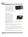
INTRODUCTION
Turbosound Aspect System Concepts
The TA-890 system is a modular point source loudspeaker system designed to deliver
extremely high fidelity audio. The system is easily scaleable from large and medium scale
concert touring applications to small clubs and events.
The Aspect system concept centres around the exceptional directivity of the patented
Polyhorn™ devices employed in the high frequency and high-mid frequency sections of the
mid/high enclosure. In contrast to the majority of conventional horns, the Polyhorns develop
a more consistent frequency response across all seats of an auditorium with minimal
interference between adjacent enclosures.
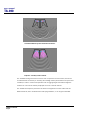
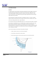
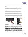
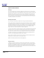
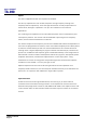
The Turbosound Polyhorn™
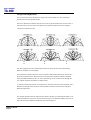
The patented Polyhorn™ devices – employed in both the high frequency and high-mid
frequency bands – exhibit a sharp cut-off at the edges of the dispersion pattern, making it
possible to produce seamless coverage of a venue with minimal destructive interference
between elements, however many individual enclosures are deployed in the cluster. The
Polyhorn™ devices generate a phase-coherent and smoothly-curved wavefront which
matches the array curvature, whose centre becomes the virtual point source.
TA-890 user manual
Page 7
user manual
TA-890
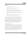
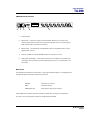
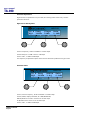
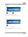
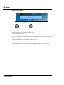
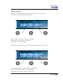
Conventional HF horns produce destructive interference
Poyhorn™ - smoothly curved wavefront
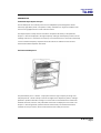
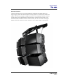
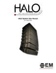
The TA-890H mid-high enclosure forms the main component of flown clusters, and can be
orientated either horizontally or vertically (the mid/high section pictured above is square and
rotatable) in order to match venue specifics such as rigging height and audience sightline
restrictions. It can also be usefully employed as a front or side fill cabinet.
The TA-890L low frequency enclosure can either be integrated in a flown cluster with TA890H enclosures, due to its identical size and flying hardware, or can be ground stacked.
TA-890 user manual
Page 8
user manual
TA-890
ASPECT TA-890 TURNKEY SYSTEM CONCEPT
Aspect is available as an integrated audio system package, comprising loudspeakers with
integral flying hardware, amplifier racks and all necessary drive and control equipment in an
extremely compact and manageable form. In addition, the system has been designed to truck
pack efficiently and handle easily.
The concept of assembling a system around standardised components ensures absolute
compatibility between users, although sufficient flexibility is built into the rack design to
allow for varying requirements such as the ratio of bass cabinets to mid-highs, or 4-way or 5way operation. Aspect systems from different sources may therefore be freely combined
without difficulty. This provides owners with a considerable competitive advantage in
servicing the requirements of international touring productions, and in co-operating with
other Aspect suppliers within the worldwide network.
The controller functions as an electronic loudspeaker management system, comprising a
24dB per octave crossover, with factory preset limiters matched to the power amplifiers,
digital time-alignment and electronically balanced inputs and outputs.
A standard Aspect integrated sound system consists of:
•
TA-890H mid-high enclosures
•
TA-890L low frequency enclosures
•
Flybars, adjustable flying chains and flybar trunk
•
Loudspeaker break-outs and multi-way extensions
•
Multi-way returns system
•
LMS-D6 or LMS-D26 system controllers
•
AMP-890 ampifier racks with:
o
T-45 and T-25 power amplifiers
o
Three phase 32A power distribution
O
Multi-way and local speaker connections
TA-890 user manual
Page 9
user manual
TA-890
The Loudspeaker Management System (LMS) Concept
Turbosound Loudspeaker Management Systems are more than just electronic crossovers.
They provide full digital alignment of all components in the Aspect enclosures, to ensure
coherent acoustic output. They also incorporates a number of features which contribute to
overall system reliability and ease of setting-up.
All system parameters such as crossover frequencies, limiter settings and equalisation can be
simply called up from a factory-set menu, making it possible to maintain consistent and
repeatable system performance.
Because the power amplifiers are included as part of the Aspect system, the controllers are
able to utilise output limiters which are precisely matched to the system requirements, being
pre-set to prevent the amplifiers from clipping. Inputs and outputs are fully balanced,
providing isolation between the controller and the amplifier inputs. These factors contribute
to high reliability in the adverse circumstances often encountered under arduous touring
conditions.
LMS-D24, LMS-D26 and LMS-D6 Loudspeaker Management Systems
Use of the LMS-D2X and LMS-D6 loudspeaker management systems ensures accurate timealignment of the system drive units and also provides a facility for users to select additional
delay, either to compensate for physical displacement of ground-stacked bass enclosures
relative to flown high packs, or to provide full range delay for correct image localisation or
use in distributed systems. It should however be noted that the high-Q, and therefore long
throw, properties of the Aspect system generally eliminates the need for distributed delayed
systems, even for very large audiences.
Amplifier Racks
Aspect amplifier racks are fully loaded and fully equipped for the most demanding concert
touring applications. They are fitted as standard with two T-25 model amplifiers and three T45 model amplifiers, Socapex speaker break-outs as well as local connectors, single phase or
three phase mains distribution, and multi-way signal input and link connectors. All the
component parts are rigidly mounted in a 12U steel space frame with removeable panels,
and housed in a road case with heavy duty wheels.
Power Amplifiers
In addition to the Turbosound T-25 and T-45 model amplifiers supplied with turnkey Aspect
systems, the following other power amplifier brands provide sufficient performance and
mechanical compatibility to perform well with Aspect loudspeaker systems:
TA-890 user manual
Page 10
user manual
TA-890
•
MC2 E series
•
Lab Gruppen FP series
•
Crest Pro series
•
QSC Powerlight II series
Digital Controllers
In addition to the Turbosound LMS-D6 and LMS-D26 loudspeaker management systems, the
following digital crossovers have been tested and are recommended for use with Aspect
systems:
•
BSS FDS366
•
XTA DP224, DP226 and DP428
Aspect Loudspeaker Components
All the drive units have been designed in-house specifically for the Aspect system and are
manufactured exclusively for Turbosound. This means that they are expressly suited to their
intended purpose, and make use of innovative features to ensure premium performance.
Neodymium magnets are used throughout all drive units. This results in higher efficiency,
less power compression and reduced overall weight. Low-mid frequency drivers are
designed to be rear-facing in the enclosure, enabling the heatsink / phase plug to be placed in
the air flow to aid cooling.
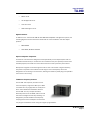
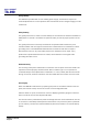
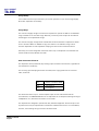
TA-890L Low Frequency Enclosure
The TA-890L low frequency enclosure covers
the low frequency range from 35Hz up to 100Hz.
It contains two very high power 15" neodymium
drive units loaded with TurboBass™ devices.
The TA-890L is a very compact enclosure,
identically sized to the TA-890H, and its minimal
size and low weight ensures easy handling. It is
designed to provide beneficial low frequency
coupling when used in multiples. The enclosure
may be ground-stacked or flown using its integral flying hardware.
TA-890 user manual
Page 11
user manual
TA-890
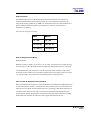
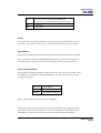
TSW-218 Subwoofer
The TSW-218 is designed to cover the sub and
low frequency ranges from 25Hz to 100Hz, and
can be used as part of a 5-way Aspect system in
order to reinforce sub-bass frequencies. It
utilises two custom designed neodymium 18”
drivers loaded with TurboBass™ devices. The
proprietary loading technique and horn flare
design produces significant mutual coupling
between adjacent enclosures, resulting in
sensitivity gains of up to 110dB with eight units coupled.
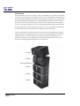
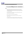
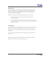
TA-890H Mid-high Enclosure
The TA-890H enclosure covers frequencies
above 100Hz and contains a total of five drive
units. A pair of 10” neodymium low-mid
frequency drivers loaded with TurboMid™
devices covers the frequency range from
100Hz to 400Hz. The low-mid drivers are rearfacing in the enclosure, providing not only
additional cooling by placing the
magnet/heatsink assemblies in the path of the
airflow, but also acting as phase plugs. A
specially developed 10” low-mid driver
loaded with a LMF Polyhorn™ device covers the range from 400Hz to 4kHz. The remaining
frequencies are covered by a pair of 50mm dome drivers loaded with Polyhorn™ waveguides
specifically designed for this purpose.
The TA-890H mid-high enclosure is designed to provide a precise array angle of 25º
horizontal x 15º vertical. This high Q provides the projection necessary for true long throw
applications such as large arena and outdoor productions.
The Polyhorn™ and TurboMid™ devices are unique to Turbosound and are covered by
principle patents world-wide. They utilise specialised forms of horn loading which provide
exceptionally low distortion and high efficiency from cone-type drive units. The subjective
effect of these devices is greater clarity and transparency of reproduction when compared
with conventional compression drivers and horns.
The TA-890H is fully equipped for all touring applications with independent flying systems.
This allows cabinets to be configured horizontally providing considerable flexibility of use.
TA-890 user manual
Page 12
user manual
TA-890
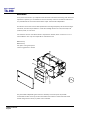
It includes a hinged rear access door, integral multi-way speaker cable, removable wheel
board, ergonomically placed flush handles, weatherised beech plywood construction and
optimised truck-pack dimensions. The TA-890H enclosure is exactly the same size as, and of
very similar weight to, the TA-890L.
TA-890 user manual
Page 13
user manual
TA-890
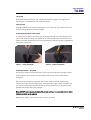
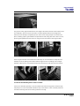
Transportation
TA-890 cabinets include a removable wheelboard which clips to the front of the cabinet,
allowing single units to be conveniently transported. These are designed to be stackable, so
that when not in use they can be neatly stored without taking up floor space. The
wheelboards will fit both mid-high and low frequency cabinets.
Up to three TA-890 cabinets can be stacked on a WB890 wheel dolly, and this allows the cabinets to be
pre-configured and locked at the warehouse using the
integral flygear. Cabinets can then be wheeled in or
out of a truck straight on to a stage area ready to be
flown. The stack is stabilised by ratchet straps which
attach to the flygear on the top cabinet and are
tightened by means of recessed levers on the wheel
dolly.
Optional heavy duty transit covers are
available for TA-890 cabinets. These
fasten at the front of the cabinet with
velcro straps.
TA-890 user manual
Page 14
user manual
TA-890
Aspect Flying Systems
To take full advantage of the very precise dispersion properties of the Aspect system, an
integral rigging system has been developed. The flying system is inherently safe, flexible and
simple to use, and even though it is integral to the box, it may be quickly and easily removed
for safety testing. The rigging design allows the creation of clusters and arrays that can be
assembled quickly and with a minimum number of crew, and with full control of the angles
between enclosures and of their vertical inclination, to suit a wide variety of requirements.
TA-890 user manual
Page 15
user manual
TA-890
FLYING AND STACKING
Overview
The Aspect system flying hardware is specifically designed to take advantage of the precise
horizontal directivity characteristics, as well as allow a wide range of adjustment of the
vertical angles between adjacent enclosures, and the overall vertical inclination of each
column of enclosures. This means that arrays can easily be optimised to suit the coverage
requirements of any situation.
Sound radiating from adjacent cabinets will successfully blend over a range of included
angles, creating a coherent point-source image, and this results in the ability to tailor both
the overall coverage and the SPL at a given distance.
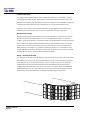
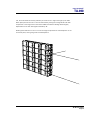
The concept of arraying the TA-890 Aspect system is to create part of the surface of a sphere.
A small part of a large sphere will form a high-directivity (long-throw) system with a high
SPL at a distance, whereas a large part of a small sphere will be of lower directivity
producing less SPL at a distance, but having a wider angle of coverage. This approach leads
to the creation of a virtual point source behind the array, where sound appears to emanate
from a single point in space.
There are some simple rules to follow to help achieve this goal:
TA-890 user manual
Page 16
•
Obtain a smooth even curve in the horizontal plane.
•
Use a similar amount of tilt on each column.
•
Ensure that the bottom corners of each column are in line with each other.
user manual
TA-890
GIGMATE™ ACOUSTIC SIMULATION
While the Aspect System is remarkably intuitive in terms of building arrays and aiming them,
and requires no theoretical calculations in order to achieve optimum coverage of a room or
audience space due to its inherent ‘point-and-shoot’ nature, there may well be situations
where some prior knowledge of a venue can save time in setting up and configuring the PA.
In order to aid in this process, Turbosound offers the GigMate™ software acoustic simulation
package, a version of the generic EASE Focus program that is based on current EASE 4.1
data.
GigMate™ provides an accurate elevation representation of sound pressure level and
coverage of a room, given the dimensions of the audience areas and location of available
rigging points in the venue. The database allows for flown clusters of TA-890 touring or TA880 trapezoidal enclosures, or for ground stacked arrays.
Setting up a Venue - Overview
The Audience Area window provides a way add or remove Audience Areas and define their
location in the space. A venue can be selected from a range of standard venue presets or set
up from scratch using the X and Y co-ordinates menus to define the location, size and angle
of the listening areas.
The PA is set up by choosing either a flown cluster or ground stack. Box count, cluster
position, tilt angle and splay angle can all be selected independently.
The mapping properties allow the user to select frequency bands from 100Hz to 10kHz and
also bandwidth from one-third octave to broadband.
Once mapped to achieve satisfactory room coverage and level, results can be saved and
printed as a .rtf file. The program will also calculate the total weight of the cluster as well as
its overall physical size.
TA-890 user manual
Page 17
user manual
TA-890
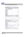
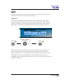
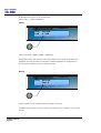
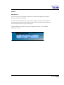
Running Turbosound GigMate™ / EASE Focus for the first time:
When you first start the program you must set the system file that it is to use. The installation
files include two Turbosound Aspect System files as shown below:
Select the Touring version cabinets. You will now be presented with the GigMate™ main
screen.
TA-890 user manual
Page 18
user manual
TA-890
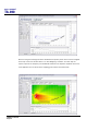
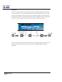
The screen is split into four main areas:
System Setup
The left hand side of the screen is where you define the system, auditorium and project. Tabs
On the bottom of this window allow you to toggle between modes.
Mapping Properties
This is the main window which will display the system as configured in the System Setup
window along with the audience areas and mappings.
Audience Area
Beneath the main Mapping Properties window this graphically displays the SPL on each
audience area, or across a combination of audience areas.
Rigging
The far right window shows the detail of the system configuration and is especially useful in
larger venues where the speakers shown in the main window become very small.
TA-890 user manual
Page 19
user manual
TA-890
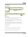
Designing a system
To design a system begin by defining the venue/audience areas by clicking on the “Audience
Area” tab in the bottom left of the screen.
Within this window you can edit or remove existing audience areas, and create new ones.
There are two methods of defining an audience area. In either case you must define the
X1/Y1 coordinate of the start of the area, you can then either enter the X2/Y2 points or its
length and angle.
As you create audience areas they are shown graphically in the main window.
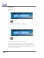
The next step is to design the loudspeaker array using the “System Setup” window. Select
the “System Setup” tab in the bottom left of the screen and begin by choosing the desired
flybar or groundstack in the drop down box at the top left of the window.
TA-890 user manual
Page 20
user manual
TA-890
Now select the number of cabinets deep that you wish to hang or stack from the “Box Count”
drop-down menu. Trim height, or PA wing height can now be set in the “Position” field.
If a mix of Low and High cabinets are to be used then select in the “Cabinet” window the
type and location in the array of each box. The angle between cabinets can now be set in the
“Angle” list. Each cabinet has an aiming line that can be used to determine the centre of each
cabinet’s dispersion. Adjust the trim height, top angle and inter-cabinet angle to achieve
optimum coverage.
TA-890 user manual
Page 21
user manual
TA-890
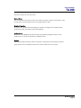
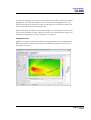
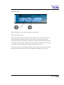
Now that the general design has been established the system performance must be mapped.
At the top of the main window there is an “SPL Mapping” checkbox. This will map the
system output at the frequency and bandwidth selected in the adjacent dropdown boxes. For
most applications a one-third octave mapping gives realistic and useful data.
TA-890 user manual
Page 22
user manual
TA-890
The Audience Area graph at the bottom of the window shows the SPL, as specified in the SPL
Mapping lists, on the selected Audience Area. The selected area is highlighted in the main
window and the graph is repeated onto each area. Selecting the “Combined Level View” tab
will show the SPL across all areas simultaneously.
Now that the system is mapped, the inter-cabinet angles or row attenuation may be trimmed
to provide the smoothest coverage. Typically the bottom row of the system will require some
attenuation and should be on it’s own “Amp way” to achieve this.
Changing the system
GigMate™ currently includes both the Aspect Touring TA-890 Series and the Trapezoidal TA880 series products. To switch between systems use Edit/Change System on the menu bar
and select from the list.
TA-890 user manual
Page 23
user manual
TA-890
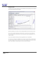
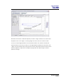
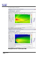
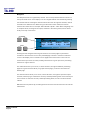
Two typical examples are shown here.
theatre-style venue: 3-wide flown cluster @ 1kHz
Small arena system; 2-wide by 5 deep flown cluster @ 4kHz
TA-890 user manual
Page 24
user manual
TA-890
Safety Notes on Rigging
The Turbosound TA-880 system has been designed and constructed to a high standard of
safety, and tested to the most demanding of specifications with a safety factor of 13:1.
Always wear protective headwear, footwear and eye protection in accordance with local
regulations. Anyone involved in flying ANY sound system, especially in a touring capacity,
should take note of the following advice:
The rigging of a flown sound system may be dangerous unless undertaken by qualified
personnel with the required experience and certification to perform the necessary tasks.
Fixing of hanging points in a roof should always be carried out by a professional rigger and
in accordance with the local rules of the venue. The house rigger and/or building manager
must always be consulted.
You should observe particularly the following points:
Inspect rigging systems and cabinets for damage before proceeding to assemble a flown
array. If any parts are damaged or suspect, DO NOT USE THEM.
When initially ratcheting a column of speakers it is good to bear in mind the expected angle
of inclination so as to avoid ending up with too much of the strap left on the ratchet. This is
important because the ratchet can only take three complete turns before it releases itself.
WARNING: If a tilt strap is released suddenly, the column of enclosures may tend to swing
violently forwards and care must be taken to avoid danger to persons in the vicinity. It is
essential to check that nobody is standing immediately in front of the column, and to give a
suitable warning, before the strap is released. Ideally, two persons should support the
column from the side whilst the strap is released, or alternatively the bottom row may be
returned to the ground before release. In any event it is essential that all personnel in the
vicinity are aware that the system is about to move and that they must keep clear.
Aspect Flying System components have been individually tested in accordance with the
following regulations:
The Health and Safety at Work Act 1974
The Supply of Machinery (Safety) Regulations 1992
The Lifting Operations and Lifting Equipment Regulations 1998
Each component is covered by a Record of Load Test Certificate, which may be obtained on
request from Turbosound, quoting the indentifying number(s) from the flying equipment. A
copy of a sample certificate is reproduced overleaf.
TA-890 user manual
Page 25
user manual
TA-890
Sample Certificate of Load Test
TA-890 user manual
Page 26
user manual
TA-890
Flying Hardware
The ‘A’ system flying bars consist as follows:
•
Single bar – supports a vertical column of cabinets up to 8 deep.
•
Twin bar – supports two vertical columns up to 8 deep.
•
Triple bar – supports three vertical columns from a single pick-up point or with chain
bridles, specifically designed for outdoor use with ground support towers
•
Mother beam – used to connect multiples of single bars and/or twin bars in a
modular fashion, allowing the creation of speaker clusters up to and including full
360° arrays.
•
Extender beam – connects half a mother beam to a two-wide bar and a single bar,
which can be bridled from one motor or picked up by two points
•
Spacer bar – used to join and maintain the distance between flying bars.
Flying boxes in their horizontal format is simply achieved by suspending vertical columns of
loudspeakers using chains attached to lifting points on the fixed angle flybars depicted
below. Based on the predicted 25° of horizontal coverage from a single cabinet, it is an easy
job to assess how many columns, and therefore which particular combination of flybars, will
be needed to achieve the required coverage. The top chains are adjustable to allow the
cluster to hang either close to the bar where trim height is critical, or further away when
more radical kelp is applied to the columns. In addition, all flybar assemblies allow the user
two options to vary the width at the flybar to accommodate deep arrays.
Wide and Narrow Flybar Settings
In order to accommodate the wide range of vertical coverage requirements dictated by a
particular venue, all flybars - except the single bar - offer two sets of lifting points, enclosure
attachment points and lifting strap points. The narrow setting is designed for a column of
cabinets in the ‘A’ or horizontal orientation and will be more than adequate for the majority
of applications. However, the wide setting provides the additional horizontal spacing at the
flybar to allow for a vertical column of up to eight cabinets deep to be flown where more
vertical coverage is called for. No additional parts or flybars are required to accommodate
virtually all situations; it can all be achieved using only one type of flybar.
TA-890 user manual
Page 27
user manual
TA-890
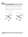
Figure 1. Single A-System Flybar FB-890/1A
The single flybar is fabricated from box steel section with integral lifting point, safety point,
enclosure suspension tabs and tilting strap pick-up point, designed to fly a single box or
vertical column of boxes up to eight deep. The bar can be flown from a single one-tonne
motor.
Single bars are manufactured as left and rights units, and so can be used to combine in a
modular fashion with double bars and mother beams to form part of larger configurations.
The net weight of the single flybar is 11kg.
FB-890/1A SINGLE FLY BAR (LEFT)
TA-890 user manual
Page 28
FB-890/1A SINGLE FLY BAR (RIGHT)
user manual
TA-890
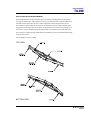
Figure 2. Double A-System Flybar FB-890/2A
A fixed angle double bar fabricated from box steel section and designed to fly two vertical
columns of cabinets up to eight deep per column. It provides alternative cabinet suspension
tabs and tilt strap points for narrow or wide configurations (when flying more than four
boxes deep the wide configuration allows for the additional amount of kelp required), plus
lifting points and safety points. A two-wide, six deep cluster can be flown from a single onetonne motor using a CB-890 chain bridle. Nylon skids are provided on the underside of the
bar to ensure it is stable during transportation and handling, and to avoid accidental damage
to the enclosure tabs.
The net weight of the bar is 42kg.
TOP VIEW
BOTTOM VIEW
TA-890 user manual
Page 29
user manual
TA-890
Figue 3. Triple ‘A’ System Flybar FB-890A/3W
A fixed angle triple bar designed to fly three vertical columns of cabinets in the ‘A’ or
horizontal orientation. It provides both narrow and wide configuration settings in order to
accommodate deep arrays of up to eight cabinets.
The FB-890A/3W can be flown using either the single lift points or the chain bridle lift points.
The net weight of the bar is 80kg.
TOP VIEW
BOTTOM VIEW
TA-890 user manual
Page 30
user manual
TA-890
FC-890 Flying Chains
An adjustable length flying chain, consisting of a top hook, chain with adjusting choke, and a
cabinet link, is used to connect the cabinets to the flybars. The top chain from the flybar to
the first cabinet can be adjusted to gain more height on the system and also improve the
looks. Alternatively if you are flying four or more cabinets deep with a lot of kelp it is good to
give the top chain some additional length as this makes racheting easier.
Chains are universal (not handed) and therefore can be used for either side of the cabinet. FC890 flying chains are load tested to 560kg.
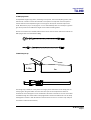
TS-890 Tilting Straps
0.59m
4m
The tilting strap, TS-890, is in two parts. The longer part is attached to the tilt strap point on
the flying bar using the buckle at its end. The other part of the strap with the ratchet is
hooked into the tilt strap point on the underside of the bottom enclosure. The free end is then
threaded through the ratchet and the strap tightened to achieve the desired tilt. The tilt strap
is designed to ratchet in both directions so that the amount of tilt on a column may easily be
increased or reduced incrementally.
TA-890 user manual
Page 31
user manual
TA-890
Three-wide hang using MB-890, EB-890, FB-890/2A and FB-890/1A
Consists of a FB-890/1A single bar and a FB-890/2A double bar, coupled with a left or right
hand side FB-890MB motherbeam and one MBE-890 left or right side extender beam. The
geometry of the system ensures that the optimum 25° horizontal angle is maintained
between columns. This configuration can be bridled from a single one-tonne point when
flying uip to three cabinets deep. When flying four or more cabinets deep up to a maximum
of six, two motors must be used.
The total net weight of this configuration is 110kg, including straps and chains.
TA-890 user manual
Page 32
user manual
TA-890
Four-wide hang using MB-890 and FB-890/2A
Consists of two FB-890/2A double bars, coupled with an MB-890 motherbeam. The geometry
of the system ensures that the optimum 25° horizontal angle is maintained between columns.
The diagrams below illustrate both narrow and wide flybar settings.
The flybar has two lifting points. These can be bridled from a single one-tonne point when
flying cabinets three deep or less on the narrow setting. For larger arrays of four or more
cabinets deep up to a maximum of eight, or when using the wide flybar setting, it is essential
to use 2 motors.
The total net weight of this configuration is 160kg, including straps and chains.
TS-890
TILT STRAP
FC-890A
FLYING CHAIN
TA-890 user manual
Page 33
user manual
TA-890
Integral Flying Hardware
Aspect cabinets are flown and connected in vertical columns by means of the integral flygear
that is rebated into the cabinet sides. In this way the load of the cluster is taken entirely
through the steelwork and not through the box. It essentially consists of a moveable drop link
that engages into a receptacle in the cabinet below with a choice of inter-cabinet angles.
All parts of the flygear are fitted flush with the woodwork of the cabinet, and can quickly and
easily be removed for safety testing.
The following diagram decribes the various parts of the flygear.
‘A’ System Flygear
TOP OFCABINET
SWING ATCH
L
DROP LINK
TILT INDEX
LATCHTRIGGER
INDEXWINDOW
TA-890 user manual
Page 34
user manual
TA-890
1. Drop Link
A retractable sliding mechanism that extends downwards to engage in the flygear of the
cabinet below. It is backed with an anti-vibration spring.
2. Swing Latch
A spring-loaded lever that secures the flying chain or the drop link of the cabinet above. Pull
back to locate the drop link, release to engage.
Connecting Flying Chains to the Cabinet
To connect the top chain to the cabinet, pull the swing latch back, insert the cabinet link into
the slot and release the swing latch. Repeat for the second flying chain. A white filled circle
visible in the safety window gives clear visual indication that the link is properly engaged and
that the box is safe to lift.
Figure 1 – insert cabinet link
Figure 2 – release swing latch
Connecting Cabinets - ‘A’ System
The optimum method is to stack cabinets in vertical columns underneath the flybar position,
ensuring that the corner locators line up properly. Cabinets can now be linked and preconfigured.
With one hand, pull back the swing latch at the top of a cabinet while at the same time
releasing the drop link on the cabinet above it using the latch trigger. Use the tilt index to set
the required vertical angles between cabinets. A white circle visible in the drop link window
indicates that the drop link is fully engaged.
Note: DO NOT under any circumstances fly cabinets until you have checked that the safety
indicator is visible on all cabinets.
Repeat this procedure until all cabinets in the column are linked.
TA-890 user manual
Page 35
user manual
TA-890
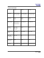
Setting Vertical Angles – ‘A’ System
The position of the tilt index determines the distance between cabinets, and hence the
vertical angle when the column is lifted. There are four possible discrete increments. The
vertical inter-cabinet angles are as follows:
Swing link position
TA-890 user manual
Page 36
Inter-cabinet angle
1 (nearest front of cabinet)
4º
2
8º
3
11º
4 (nearest rear of cabinet)
15º
4º
8º
11º
15º
user manual
TA-890
Attaching the Tilt Straps
When all cabinets have been linked and the top chains attached, the tilt straps can now be
attached.
First attach the longer strap to the flybar by sliding the flat buckle into the tilt strap
attachment point. Slide the flat buckle on the shorter strap into the tilt strap point on the
bottom of the cabinet, insert the free end of the strap through the centre of the ratchet
spindle, and pull to apply some tension before ratcheting the column.
WARNING
The tilt strap is designed to ratchet in both directions, an improvement over previous
versions which did not allow incremental tilt reduction. However, at all times please note that
if the tension on the strap is released suddenly, the column of enclosures may tend to swing
violently forwards and care must be taken to avoid danger to persons in the vicinity. It is
essential to check that nobody is standing immediately in front of the column, and to give a
suitable warning, before the strap is released. Ideally, two persons should support the row
from the side whilst the strap is released, or alternatively the bottom row may be returned to
the ground before release. In any event it is essential that all personnel in the vicinity are
aware that the system is about to move and that they must keep clear.
Fig 1 – attach buckle
Figure 2 – take up slack
SAFETY NOTE: The Turbosound TA-890 system has been designed and constructed to a
high standard of safety and tested to the most demanding of specifications with a safety
factor of 13:1. However, anyone involved in flying ANY sound system, especially in a
touring capacity, should take note of the following advice: The rigging of a flown sound
system may be dangerous unless undertaken by qualified personnel with the required
experience to perform the necessary tasks. Fixing of hanging points in a roof should
always be carried out by a professional rigger and in accordance with the local rules of the
venue. The house rigger and/or building manager must always be consulted.
TA-890 user manual
Page 37
user manual
TA-890
Turbobass Directivity
The Aspect series TA-890L bass bin and the TSW-218 subwoofer are “Turbobass” devices,
comprising horn-loaded drivers. Whilst this horn loading does aid in tuning the device and
adding some sensitivity, the relationship between horn length and the bandwidth covered by
the enclosures means that each source is effectively an omni-directional point source.
Therefore any LF pattern control experienced when using an Aspect system derives from
adjacent enclosures within an array or from the relationship of a left to right stack
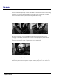
Bass Enclosure arraying
Aspect bass enclosures are most efficient when ground stacked in a block. Not only do they
benefit from improved coupling when there are no air gaps between them, but they also
couple to the ground. However, some of this energy may be absorbed by nearby obstructions
such as barriers or a tightly-packed standing audience. Sound pressure levels may also be
excessive for members of the audience if they are able to get too close to the enclosures.
When stacking on the stage or on a platform, particularly outdoors, it is preferable to close
the gap between the platform and the floor with sheets of plywood. This results in increased
sound projection into the audience and less leakage backstage.
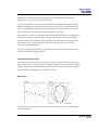
Aiming - directivity of the stack
The directivity of the bass stack will depend on its dimensions and curvature. A tall thin stack
will disperse a lot in the horizontal plane and become narrow in the vertical plane whereas a
wide stack will narrow in the horizontal plane. There is usually an optimum compromise
between the two so that a smooth transition can be obtained between the effect of the
coupling of the two stacks down the centre line of the room and the effect of the individual
stacks beaming on their axis. Also adding some curvature to the stack will help to increase
the directivity of the stack especially in stopping beaming at higher frequencies.
TA-890 user manual
Page 38
user manual
TA-890
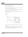
Tall, thin bass stacks work best, preferably in blocks of six or eight bins high by two wide.
When space permits use two or three of these blocks, placing the onstage block flush with
and parallel to the stage, with a second and additional identical offstage blocks slightly
separated from the first and angled outwards by 40°.
Stacking bass cabinets in a line in front of the stage will produce narrower dispersion in the
horizontal plane, while giving wide vertical dispersion.
TA-890 user manual
Page 39
user manual
TA-890
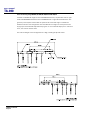
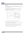
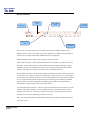
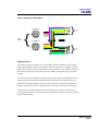
The typical Left to Right problem
One of the most common problems on large scale events results from the relationship
between the left and right bass stacks.
Due to the difference in distance and arrival time at any point between two point sources, in
this case bass arrays, there will inevitably be some positive addition and some negative
cancellation between sources.
A
B
C
D
E
F
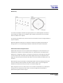
The above graphs show the relationship between two point sources when separated by
different multiples of a wavelength.
The cancellations shown above are due to the phase relationship between two sources at a
given point between them. When the sources are perfectly in phase the addition between
them gives 6dB of additional gain. If, due to positioning, one of the sources is 180 degrees
out of phase complete cancellation is experienced.
To further illustrate the problem it is important to remember that since each frequency has a
different wavelength the summation and cancellation between enclosures will change at
different frequencies.
For example presume that two bass bins are spaced 11ft apart (a wavelength at 100Hz) so at
100Hz the dispersion from the 2 sources will be as figure C. At 50Hz the dispersion will be as
figure B. Similarly at 200Hz the dispersion will look like figure E.
TA-890 user manual
Page 40
user manual
TA-890
Whilst several manufacturers have attempted to solve this using DSP based systems at
present there is not a working solution in the market.
In theory by splitting the LF energy into several bands and then spacing the left/right stacks
differently depending on frequency this effect can be solved or at least minimised. However,
due to the available space within a venue and the maximum roll-off available from common
crossover systems we consider this to be neither effective or practical.
If a large system is going to be configured with left and right bass stacks it can be preferential
to stack the bass bins in a wide fan with the onstage column flush and parallel to the stage
and with a large distance between the left and right stacks. This ensures each bass array has
some pattern control. Angling individual columns outwards also helps to minimise the
cancellation effects detailed above.
There are several ways of minimising cancellation problems, involving different numbers of
enclosures and different stacking options.
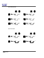
Creating Directional Bass arrays:
It is possible to build bass arrays which provide an amount of horizontal pattern control and
also go some way to solving the problem of multiple summation and cancellations on a large
system. All the examples detailed below presume that the enclosures are placed in free space
and are therefore not effected by the constraints of a venue.
Bass in a line:
The above balloon shows the pattern control given by spacing units ¼ of a wavelength apart
@ 50Hz (5.5ft apart).
TA-890 user manual
Page 41
user manual
TA-890
The result here is tight horizontal pattern control with two side lobes. This is a common
application of subwoofers used in the field.
There are however, several points to notice.
Firstly, almost as much energy is produced behind the array as in front of it, which can create
problems on stage or on multiple-staged outdoor events.
At the same time this will always provide a tightly controlled beam, providing focused low
end energy which will drop off sharply outside the coverage area.
On a large site it will be necessary to extend the line to multiple sources in order to provide
enough horizontal coverage.
Fanned bass
Again the sources are spaced ¼ of a wavelength apart however this time there is a 15 degree
arc across the array.
The result here is a broader horizontal dispersion than the previous example. This solves the
issue of a beam of bass being too tight, but can further accentuate problems on stage due to
the tightly focused LF energy behind the middle of the array.
TA-890 user manual
Page 42
user manual
TA-890
Bessel Array
In the above example five bass bins are again spaced ¼ of a wavelength apart. However in
this example the outside two are reduced in gain by 3dB. The inside pair are out of phase
while the middle unit is in phase.
This is known as a Bessel array, and will create the smoothest horizontal coverage possible at
a given frequency.
Whilst this approach works well it is important to balance this against the practicality of
setting up three or more discreetly processed LF bands within the system architecture.
General observations of long lines of bass
Aspect bass enclosures cross over at 100Hz into the mid/high box. This means that a lot of
the punch from a kick drum is provided by the 2 x 15” bass enclosure. If the bass bins are
deployed in a configuration based on a long line across the front of the stage it is important
to ensure that the top of the stack is above head height (which may not be possible due to
sight lines restrictions) as the audience will absorb some of the attack provided by the 2 x15”
enclosure.
With extremely long lines of bass the relationship between the flown mid/high clusters and
the line of bass can create a problem around the crossover point, as the time alignment
between the enclosures can only be correct in a limited coverage area.
When using both the 2 x 15” bass bin and 2 x 18” ultrasub it is desirable to try and keep the
enclosures in the same plane as each other to avoid time alignment and cancellation
problems through the crossover region.
TA-890 user manual
Page 43
user manual
TA-890
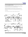
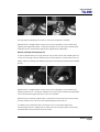
End firing array
Under today’s market conditions it is often necessary to abide by strict environmental
considerations. This is particularly pertinent at open air festival sites where there are multiple
stages and external noise limits.
Aspect TA-890H mid/high boxes are uniquely positioned in a line array dominated
marketplace to deal with this problem by allowing the user to tailor the horizontal and
vertical dispersion to the desired coverage area.
It is also possible to do this with the low end by creating a cardioid subwoofer array.
The above example shows the performance of a cardioid subwoofer array.
The main bass stack is firing forward. A second bass stack is placed behind the first by ¼ of a
wavelength @ 100Hz, out of phase and delayed by 2.5ms.
This creates a cardioid pattern dispersion pattern and will result in very steep reduction of LF
behind the stack – this is ideal where a very controlled environment is required.
It is worth noting that this requires additional processing and will result in a lower output
than using the enclosures in a more conventional manner.
TA-890 user manual
Page 44
user manual
TA-890
Summing up
Generally left and right bass stack are deployed. These should be kept as far apart as
possible, and stacked high or fanned to minimise beaming. Toeing these out can hep to
reduce cancellation between left and right stacks.
On large sites or in situations where left to right cancellation is particularly bad, a fan shaped
array will solve the problem. When possible smoother coverage can be obtained by using
additional processing to create a Bessel array.
If noise pollution is a serious problem and space and logistics permit it is desirable to create
an end-firing array. Whilst this will not help solve any left to right cancellation this will
greatly reduce the amount of energy produced behind the array.
Whenever practical, when spacing the enclosure ¼ of a wavelength apart do so at around
80Hz with Aspect TA-890L enclosures but lower at 60Hz when used in combination with the
TSW-218.
Deployment of large scale sound systems is often a compromise it is advisable to explore
these possibilities well in advance of a show to determine the best possible results for the
venue. Always remember that large amounts of LF energy a short distance from the audience
area may well cause hearing damage if deployed poorly. Turbosound accepts no
responsibility for loss of hearing due to the misuse of our systems.
TA-890 user manual
Page 45
user manual
TA-890
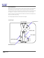
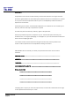
Ground stacking
In certain situations, indoors or outdoors, it may not be possible to fly any part of the system.
In this case, the same general rules apply as for flown arrays. High packs should be kept well
above head-height and angled carefully for even coverage. The integrated ‘A’ system flygear
permits convenient ground stacking of both 890H mid-highs and 890L low cabinets. Small
wood blocks (acoustic compensators) may be used to tilt mid-high cabinets downwards for
the floor areas while the flygear is used to give predictable upwards angles, with the TS-890
tilt strap being used to lock the top cabinet in position. Various combinations of cabinets up
to seven boxes high can be assembled to suit differing venue requirements.
In the example below, the first three cabinets are bass enclosures, stacked with the flygear
loacked and with zero angle between them. These provide ground support by elevating the
mid/high cabinets to a suitable height (the HF section of cabinet 4 is approximately 1.8
metres from the ground). A compensator is inserted between cabinets 3 and 4 in order to
point the first mid/high slightly downwards onto the audience
5.TA-890H
4.TA-890H
insert compensator here
3.TA-890L
2.TA-890L
1.TA-890L
TA-890 user manual
Page 46
user manual
TA-890
LMS SERIES LOUDSPEAKER MANAGEMENT SYSTEMS
Introduction
This section is provided with the aim of assisting sound engineers, installers and consultants
to fully understand Turbosound Loudspeaker Management Systems, and to obtain the full
benefit of their capabilities.
The LMS-D6 and LMS-D26 are dedicated Loudspeaker Management Systems, specially
configured for Turbosound's Aspect Systems, and to be used in conjunction with
Turbosound AMP-890 amplifier racks.
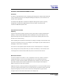
General features & facilities
Unpacking
As part of Turbosound's system of quality control, this product is carefully checked before
packing, to ensure flawless appearance. After unpacking the unit, please inspect for any
physical damage and retain the shipping carton and all relevant packing materials for use
should the unit need returning.
After unpacking the unit please check carefully for damage. If damage is found, please notify
the carrier concerned at once. You, the consignee, must instigate any claim. Please retain all
packaging in case of future re-shipment.
There will be a small packet of spare fuses with the unit. Please keep them in a safe place.
If any damage has occurred, please notify your dealer immediately, so that a written claim
for damages can be initiated. See the Warranty section at the end of this manual.
Mechanical Installation
A vertical rack space of 1U (44mm / 1.75") is required for each unit. If used in a mobile or
transportable system, the unit must be supported at the rear by additional bracing or
shelving, to prevent vibration-induced metal fatigue of the racking ‘ears’. Failure to do this
will impair reliability and invalidate the Warranty. The rack casing will need a depth of
425mm (minimum) to clear the connectors.
Adequate ventilation must be provided by allowing sufficient room around the sides and rear
of the unit to permit free circulation of air. Forced cooling is not required, a factor which aids
component longevity. The front of the unit should not be exposed to long term direct
sunlight as this can have a detrimental effect on the display lens.
TA-890 user manual
Page 47
user manual
TA-890
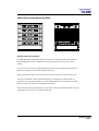
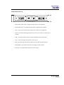
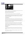
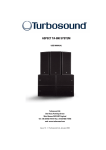
LMS-D6 Front Panel Functions
5
4
LMS-D6
3
<BACK
NEXT>
MENU
ENTER
6
FREQ
9
'Q'
GAIN
10
A
B
11
1
CLIP
TQ-440
GAIN
8
3
LIM
-3
MUTE -24
4
5
LIM
LIM
-3
MUTE -24
-3
MUTE -24
6
LIM
-3
-3
-24
-24
OUT
DIGITAL LOUDSPEAKER MANAGEMENT SYSTEM
1
2
LIM
-6
-24
BYPASS
12
GAIN
7
GAIN
GAIN
GAIN
GAIN
GAIN
GAIN
2
1.
LCD Display - Shows menu options, output information and adjustment parameters.
2.
Gain Keys - Two input and six-output ‘gain’ keys allow instant access to the gain
screen for each channel. Pressing a second time selects the last function edited.
3.
Next Key - Moves the display forwards through the list of available parameters for
the current input or output channel.
4.
Back Key - Moves the display backwards through the list of available parameters for
the current input or output channel.
5.
Menu Key - Activates the main menu on the LCD display. Pressing a second time
selects the last menu edited. Different menus are selected by pressing the ‘BACK’
and ‘NEXT’ keys or using the ‘FREQ’ control.
6.
Enter Key - Enters the chosen menu and confirms menu selections.
7.
OUT Key - Exits the menu.
8.
Bypass Key - Allows the currently displayed parametric section to be bypassed.
(Note: The Highpass / Lowpass filters and limiters can not be bypassed.)
9.
Parameter Controls - The three velocity sensitive rotary encoders allow the relevant
parameter, on the LCD screen, to be adjusted.
10. Input Meters - Displays available headroom before input clipping occurs. The
bottom green LED is set at -24dB, with the orange 0dB LED set at 3dB below
clipping. The top, red LED displays digital overflow and can therefore light without
all the other LEDs becoming illuminated.
11. Output Meters - Displays headroom before limiting occurs. The bottom green LED is
set at -24dB, with the orange ‘LIM’ LED set at the limiter threshold for that channel.
The top, red LED indicates 4dB of limiting.
12. Mute Keys – One mute key per output channel.
TA-890 user manual
Page 48
user manual
TA-890
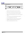
LMS-D6 Rear Panel Functions
RS232
DATA INPUT
WARNING / AVIS
OUTPUT 6
OUTPUT 5
OUTPUT 4
OUTPUT 3
OUTPUT 2
OUTPUT 1
INPUT B
INPUT A
DO NOT EXP OSE TO RA IN OR MOIST URE
THIS EQUIPMENT M UST BE EARTHED
SHOCK HAZARD – DO NOT REMOVE COVER S
RISQUE DE CHOC ELECTRIQUE - NE PAS OUVRIR
PROTECTION AGAINST FIRE
REPLACE ONLY WITH THE
SAME TYPE T1A, 250V FUSE
1
2
3
PIN1=SHIELD
PIN2=HOT
PIN3=COLD
CUSTOM MADE FOR TURBOSOUND
IN THE UK BY XTA ELECTRONICS
4
5
1.
Power Switch.
2.
Mains Fuse - Located in a finger-proof fuseholder adjacent to the mains inlet.
Always replace this fuse with the correct type as shown on the rear panel legend.
(N.B. A spare fuse is located in this holder.)
3.
Mains Power - Connected via a standard IEC socket. A compatible power cord is
supplied with the unit.
4.
External - RS232 via a 9-pin DIN DEE socket, for connection to a PC.
5.
XLR Inputs and Outputs - 3 pin XLR connectors are provided for each audio input
and output. All terminations are fully balanced, pin 2 Hot, pin 3 Cold and pin 1 not
connected.
Mains Power
The LMS-D6 must always be connected to a 3 wire grounded AC supply. It is supplied with a
standard IEC power cord with conductors as follows:
BROWN
Power line Live (Phase)
BLUE
Power line Neutral
GREEN/YELLOW
Safety Earth and ground connection
Units supplied to the North American market are fitted with an integral moulded 3 pin
connector, which is provided to satisfy UL & CSA safety standards.
TA-890 user manual
Page 49
user manual
TA-890
Voltage Setting
The LMS-D6 is provided with an auto-seeking power supply, and therefore requires no
external adjustment for correct operation with international AC line voltages ranging from 60
to 250 volts.
Safety Earthing
The green/yellow wire of mains cord must always be connected to the electrical installation's
Safety Earth or Ground. It is essential for personal safety, as well as proper operation of the
unit.
The green/yellow wire is internally connected to all exposed metal surfaces. Any rack
framework which this unit might be mounted into is assumed to be connected to the same
grounding circuit. The LMS-D6 has balanced audio connections and does not require
disconnection of this or any other safety earth for the avoidance of hum loops. If any
problems are experienced with hums or buzzes, careful attention to the signal cable
grounding will effect a cure.
AC Power Fusing
The incoming mains power fuseholder is mounted on the rear panel. If the fuse needs to be
replaced it must be properly rated as follows: 20mm 1A 250 V type T. It is important for
continued safety that this specification is adhered to. It is very unlikely that this fuse will fail
during normal use, and such a situation must be treated with some caution as to the cause.
Powering Up
When the LMS-D6 is switched on by operating the power on-off switch located on the rear
panel, the internal circuitry carries out a series of routine diagnostic tests.
After the switch-on cycle, the screen will revert to displaying the delay program name that
was in use when the unit was last powered down.
The internal memory automatically saves all settings when the unit is switched off, so there
is no need to re-load delay and temperature information every time the system is poweredup. The memory contents are retained indefinitely without the need for an internal backup
battery.
TA-890 user manual
Page 50
user manual
TA-890
Audio Connections
The LMS-D6 audio inputs are RFI filtered and electronically balanced. The outputs are
electronically balanced and fully floating. Overall, the unit is designed to operate at any
signal levels ranging -10dBu up to +20dBu. The outputs will drive into loads of 600 Ohms or
greater and both inputs and outputs are intended to be 'fuss free', regardless of an
installation's complexity.
The connector wiring is as follows:
INPUT
OUTPUT
PIN 1 N/C
PIN 1 N/C
PIN 2 HOT (+)
PIN 2 HOT (+)
PIN 3 COLD (-)
PIN 3 COLD (-)
Input and Output Connector Wiring
Balanced Wiring
Whether a system is wired to a 'pin 3 hot' or a 'pin 2 hot' convention will not matter as long
as the wiring of hot & cold phases to both the input and output XLR connectors is the same.
At the LMS-D6 input, the convention is 'screen goes forward with the signal'. Input cable
screening therefore needs to be connected at and derived from the signal source end, as pin
1 on the input XLR is not connected to the LMS-D6 chassis nor signal ground.
Time correction for loudspeaker driver placement
When a loudspeaker sound system is constructed which utilises different loudspeaker drivers
for separate frequency bands, it is inevitable that the sound sources are non-coincident. The
effect of this is that phase and time differences occur, producing a substantial cancellation of
the signal around the crossover region. There is also a general lack of transient clarity or
smearing of the sound, resulting from an inaccurate combining of the wavefront. The LMSD6 provides and maintains the optimum relative signal delay between drivers.
TA-890 user manual
Page 51
user manual
TA-890
LMS-D24 AND D26 LOUDSPEAKER MANAGEMENT SYSTEMS
Features
•
Minimal signal path design, providing exceptional audio quality with carefully
optimised processing and high performance converters for a full >111dB dynamic
range, 96kHz sampling rate and minimal filtering. Audio-grade capacitors are used
in the analogue signal path.
•
Sonically superb ADC / DAC combination; a carefully matched pairing of the best
devices from Burr Brown and Wolfson.
•
Newly released family of Analogue Devices SHARC DSP.
•
Extended bandwidth; 96kHz sampling frequency provides for a nominally flat
response to 40kHz.
•
Front panel parameter rotary encoder provides a familiar and easy to use control
format with all filter information displayed simultaneously on a backlit LCD display.
TA-890 user manual
Page 52
user manual
TA-890
Front Panel Functions
Channel Select
buttons
Store and
Recall buttons
Input Signal
Indicators
2x 24 character
LCD
Limiter
Indicators
Parameter Edit
Encoders
Edit Parameter
Select buttons
Output Mute
buttons
Input Signal Indicators – A set of three pairs of LED’s indicate signal present, +4dBu and
input clip for both channels. The signal present LED’s operate at approximately –40 dBu,
giving a useful indication of even relatively low input signal levels. The +4 dBu LED’s are
intended to show nominal operating level and can also be useful for setting system gain
structure. Clip LED’s warn the user of input overload and operate at +19 dBu.
Program Store and Recall – these controls provide access to 45 presets. Pressing the store
button allows the user to name a preset and choose which memory location it will be held in.
Pressing store button again completes the process. The Recall function operates in a similar
way, pressing the recall button allows the user to select which preset they require, pressing
the button for a second time, then confirming, recalls the new DSP settings. The unit allows
the user to set up user programs with full access to all parameters.
Note that presets cannot be stored or recalled when secure mode is activated.
Channel Selection Buttons – the currently selected channel is displayed on the top left hand
corner of the LCD. Pressing the channel buttons scrolls through the available input and
output channels and finally through the utility functions and back to the default screen. If
operating a stereo-linked preset the channel name will indicate the channel pairing. For
example ‘A+B’ means both input A and B parameters. The name of the output will be shown
briefly at the top of the display when stepping onto an output.
TA-890 user manual
Page 53
user manual
TA-890
Edit Select Buttons – the currently selected edit parameter is displayed on the bottom left
corner of the LCD. Pressing the edit select buttons moves through the available parameters
for the current input or output.
Text display – preset, channel, parameter and status information is shown on the 2x 24character text display. In most screens the currently selected channel is displayed on the
upper line and the edit parameter on the lower line. To simplify the display and enhance
security, some parameters or parameter pages are omitted when not relevant.
Parameter Knobs – three velocity sensitive parameter knobs are used to adjust parameters
shown on the display. Up to three parameters are displayed on the screen. The parameter
name is shown above the parameter value in each of the three screen sections. The
parameter knobs have a fixed association with the screen sections; the rightmost parameter
knob adjusts the rightmost parameter and so on.
Output signal and limiter indication – two LED’s are provided for each output channel. These
show the signal level relative to the limiter threshold. The yellow LED will light when the
signal is 6dB below the threshold and the red warning LED will light when the limiter
threshold is reached.
Mute buttons and status LED’s – each output has a mute button and associated mute status
LED. Pressing the button toggles the mute on and off.
Note that the mute buttons do not function when the Secure Mode is activated.
Secure Button (on the rear) – a momentary button is fitted behind the rear panel, between
the output XLRs and the RS232 port. When activated, this will disable all the front panel
controls so they cannot affect the signal path, making the unit secure against tampering.
When in secure mode, the indicators still operate normally.
Note that the communications port is still active in secure mode.
TA-890 user manual
Page 54
user manual
TA-890
Rear Panel Functions
Expansion
Port
Power Inlet
Secure Mode
Switch
Audio Input
Connectors
Serial Comms
Port
Audio Output
Connectors
Power Inlet – provides connection to a suitable mains electricity supply using the cable
supplied. The controller has a switch mode power supply that is capable of operating with a
nominal mains voltage of 80 to 240v, 50/60Hz without re-configuration.
Network expansion port – where a future network card can be fitted.
Audio Input connectors – these are fully balanced and are wired pin 1 ground, pin 2 hot and
pin 3 cold. The two inputs have pin 1 connected directly to the chassis and feed the signal
processing chains. If an unbalanced source is used, a connection should be made between
the pin 3 ‘cold’ signal and the ground connection of the unbalanced source.
Audio Output connectors – the processed outputs are impedance balanced, and are wired
pin 1 ground, pin 2 hot and pin 3 cold. An unbalanced input may be driven by by connecting
pin 3 ‘cold’ signal to the ground connection of the unbalanced destination input. Note that
output pin-1’s are ground lifted at audio frequencies but connected to ground at RF for good
EMC performance. The intention being that the amplifiers the processor is driving should be
responsible for the grounding of their input cable shields.
Communications port connector – the unit may be controlled entirely from another
controller (typically a Personal Computer), running an application that is compliant with the
ObCom standard. Connection will normally be made to the controller via this serial port
connector. This port is also used for updating the firmware in the unit.
Note: The communications port is NOT disabled when the front panel is made secure using
the secure button.
TA-890 user manual
Page 55
user manual
TA-890
OPERATING THE LMS-D24 AND D26
Starting up
The unit will energise as soon as power is applied to the IEC inlet; there is no power switch.
During the start up process the firmware application model number and version numbers are
displayed and the outputs are muted until the unit has completed its internal checks. Once
the start-up routines are complete and the unit is ready to pass audio, the DSP signal path
will be restored to the current settings when it was last powered down and the audio signal
is gradually ramped up to its correct level.
Selecting a Factory Preset
There is a library of thirty Factory Presets to suit a range of Turbosound enclosures.
Factory Presets contain some parameters that are fixed and hidden from view; the remainder
of the DSP parameters are available for user manipulation. The number and type of hidden
parameters is dependant on the Factory Preset, typically crossover frequencies, output delay
and some EQ’s are hidden; those settings that are a function of the loudspeaker cabinet
design and should not require adjustment for different applications.
To recall a Factory Preset for a particular cabinet or system, press Recall and use the left hand
parameter knob A to scroll through the available factory preset locations (as indicated by a
box symbol after the preset number). Once the appropriate preset has been selected press
recall again, at which point you will be asked to confirm the action by pressing recall for a
third time. This is to guard against accidental recall of Presets.
Factory Presets are locked so they cannot be over-written. The user can, however, store an
edited version of a Factory Preset in any free preset location.
Details of all the Factory Presets can be found in Appendix A.
Creating a Crossover
In addition to the Factory Presets the unit has two further ‘Base Presets’; mono and stereo.
These Base Presets are stored in locations 1 and 2 respectively, they can be used to develop
settings for any loudspeaker combination and are recalled in the same way as the Factory
Presets described above. These Presets are also locked but the user can name and store their
own edited versions in any free preset location.
TA-890 user manual
Page 56
user manual
TA-890
Navigation and Viewing Parameters
(Note: The LMS-D26 is shown in all the following screen shots; however the features and
parameters apply equally to the LMS-D24)
Many of the processing elements in each input and output path have features that may be
controlled by the user, such as gain, frequency or limiter threshold. We call these adjustable
features parameters.
LMS-D26
In A Freq
EQ1 100Hz
Width
1.4Q
b
a
a
Gain
0.0dB
b
c
c
A parameter may be adjusted when it is displayed by turning one of the three-parameter
knobs. Each of the three-parameter knobs is associated with a zone on the display. Adjusting
the leftmost parameter knob will change the value of the parameter showing in the leftmost
zone of the display and so on. Turn a knob clockwise to increase the value of a parameter, or
anti-clockwise to decrease it. The knobs are velocity-sensitive so turning a knob rapidly will
cause the action to ‘accelerate’, so the value changes more rapidly.
TA-890 user manual
Page 57
user manual
TA-890
Navigation
The DSP parameters are organised by channel. The currently selected channel is shown in
the top left hand corner of the display. You can navigate between the channels by pressing
the channel buttons. Pressing the channel buttons will scroll through the channels, utilities
and back to the default screen. When using a Preset that is stereo linked, the channel
selection will reflect this. For example ‘1&4’ indicates outputs 1 and 4. When navigating onto
an output channel, the usage of the output, as define in the factory preset, will be shown
briefly at the top of the screen.
CHANNEL
LMS-D26
EDIT
Out1 Freq
EQ1 100Hz
a
Width
1.4Q
b
Gain
0.0dB
c
Pressing the edit navigation buttons gives access to the various pages of parameters
available for each channel. The currently selected page is shown in the bottom left hand
corner of the display, this is omitted on some pages where the function is obvious. The
screen shows up to three (normally related) parameters for a given part of the processing
functions on a given channel.
The edit buttons allow you to scroll, in either direction, through the different processing
pages for a given Channel. When you go past the last page, you will be returned to the
default page.
The channel buttons allow you to scroll, in either direction, through the input and output
channels, whilst trying to maintain the currently viewed processing block. If the channel you
scroll to does not have the currently viewed processing block, the next one will be shown
instead.
NB. When the unit powers-up, the settings will be the same as those when the unit was last
switched off.
TA-890 user manual
Page 58
user manual
TA-890
PRESETS
The device contains a total of forty-five user and Factory Presets. The user cannot overwrite
the basic mono, basic stereo or Factory Preset programs.
Preset Recall
To select an existing Preset, press the Recall Button so the indicator above it illuminates.
Turn parameter knob A until the required Preset number is shown on the display. Factory
presets are indicated by a box symbol appearing after the preset number. Press the Recall
Button again to activate the Preset. Pressing any other button will cancel the operation.
LMS-D26
Preset Name
Recall 32
My System
a
RECALL
SELECT PRESET
TO RECALL
b
c
RECALL
a
Users can develop their own Preset based on one of the basic or Factory Presets stored
within the device. Once a basic or user Preset has been recalled, a user has complete
freedom to adjust any or all of the parameters. Factory Presets can be used as the basis for
user Presets but they have some parameters that are predefined as a function of the
loudspeaker system. These parameters are ‘hidden’ from the user, as they should be constant
regardless of application.
TA-890 user manual
Page 59
user manual
TA-890
Preset Store
To store the current Preset in a user location, press the Preset Store Button so the indicator
above it illuminates. Turn the first parameter knob until the required Preset location number
is show on the display. A Preset name of up to 12 characters in length can be entered using
parameter knobs B and C. Pressing the Store Button again completes the process and stores
the Preset. As with Preset Recall, pressing any other button cancels the operation.
LMS-D26
Preset Name
Store 32
My System
a
STORE
b
c
SELECT STORE
LOCATION
a
STORE
b
c
NAME PRESET
The user can overwrite non-protected Presets only; if an attempt is made to save a Preset in a
location already occupied by a basic or Factory Preset a ‘LOCKED PRESET’ message is
displayed.
TA-890 user manual
Page 60
user manual
TA-890
DSP PROCESSING LAYOUT
Input DSP block diagram
Input A
Input
LED’s
Input
Gain
Delay
4th Order
HPF
Low
Shelf EQ
Six Band
PEQ
High
Shelf EQ
Routing
SUM
- 6dB
NB. Channel B processing is
identical to Channel A but for
clarity it is not shown
Input B
Output DSP block diagram
Delay
8th Order
HPF
8th Order
LPF
Low
Shelf EQ
Six Band
PEQ
High
Shelf EQ
Output
Gain
Mute
Limiter
Routing
Metering
Stereo / Mono Formats
There is only one ‘standard’ layout of the processing blocks, but flexible routing and control
linking allows this layout to be adapted to a wide variety of applications.
There are two ‘Formats’, Mono or Stereo. With the Mono format, all outputs have unique
parameter settings, and all outputs are identical in terms of processing functions and routing
capability. This is the most flexible Format.
Stereo format pairs the inputs and outputs for stereo operation, the parameters of each
member of the pair being identical. The routing of inputs to outputs is fixed. This format is
intended for symmetrical stereo operation, eliminating the need to make identical parameter
adjustments for each channel.
The channel pairing is:
Left and Right Inputs
Outputs 1 (routed from L input) and 3 (routed from R input) [1 and 4 for LMS-D26]
Outputs 2 (routed from L input) and 4 (routed from R input) [2 and 5 for LMS-D26]
Outputs 3 (routed from L input) and 6 (routed from R input) – LMS-D26 only]
TA-890 user manual
Page 61
user manual
TA-890
DSP PROCESSING
Input Channels
GAIN
LMS-D26
In A
Gain
0.0dB
a
c
b
a
Knob A: Gain, adjustable in 0.2dB steps from –80 dB to +20dB
DELAY
LMS-D26
In A
Delay
1.50ms
a
b
c
a
Knob A: Delay, adjustable in variable steps from 0 to 400ms
The delay parameter is adjustable in fine steps at low values; the adjustment becomes
progressively coarser as the value increases. The velocity sensitive Parameter Knobs
therefore provide accurate setting of driver offset delays (typically below 10ms) and rapid
setting of longer system alignment delays.
TA-890 user manual
Page 62
user manual
TA-890
HIGH PASS FILTER
LMS-D26
In A Freq
Shape
HPF 20.0Hz LR24
a
a
b
c
b
Knob A: Frequency, out (off), 10.0Hz to 25.6kHz in variable steps
Knob B: high pass filter type
System high pass filtering is provided for the input signal. This is the preferred location for
high pass filtering as it affects all outputs and can therefore improve inter-band phase
relationships. Filter type is selectable from Butterworth, Bessel, Linkwitz-Riley and Hardman.
Filter slopes of up to 4th order or 24dB / octave are provided. Not all filter types are available
in all slopes. For example 18dB / octave Linkwitz-Riley filters do not exist.
The Hardman type filter is always described by its’ order as the filter becomes progressively
steeper rather than following a linear slope so a dB/octave description is not accurate.
TA-890 user manual
Page 63
user manual
TA-890
Parametric Equalisation
Eight sections of equalisation are provided, two shelving filters and six fully variable
parametric sections.
High and Low shelving filters
LMS-D26
In A Freq
EQ1 100Hz
Slope
12dB
c
b
a
a
Gain
0.0dB
b
c
Knob A: Frequency, 10.0Hz to 25.6kHz in variable steps
Knob B: Slope, 6 to 12dB / octave in 1dB steps
Knob C: Gain, +/-15dB in 0.2dB steps
The frequency is specified as point where the filter deviates by 3dB from the gain value.
Parametric filters
LMS-D26
In A Freq
EQ1 100Hz
Width
1.4Q
b
a
a
b
Knob A, Centre Frequency, 10.0Hz to 25.6kHz in variable steps
Knob B, Width, display selectable, Q or BW (Bandwidth)
BW adjustable from 0.05 to 5 octaves in variable steps
Q adjustable from 14.2 to 0.2 in variable steps
Knob C, Gain, +/-15dB in 0.2dB steps
TA-890 user manual
Page 64
Gain
0.0dB
c
c
user manual
TA-890
OUTPUT CHANNELS
Gain and Polarity
LMS-D26
Out1 Gain
0.0dB
Pol
Rev
a
a
c
b
b
Knob A: Gain, adjustable in 0.2dB steps from –80 dB to +20dB
Knob B: Polarity, selectable, normal or reversed with reference to other outputs
Delay
LMS-D26
Out1 Delay
1.50ms
a
b
c
a
Knob A: Adjustable in variable steps from 0 to 80ms
As for input delay, velocity sensitive Parameter Knobs provide finer adjustment at low levels
and rapid selection of higher values.
TA-890 user manual
Page 65
user manual
TA-890
High and Low Pass Filters
LMS-D26
Out1 Freq
LPF 2.50k
Shape
LR24
a
a
b
c
b
Knob A: Frequency, <<out, 10.0Hz to 25.6kHz, out>>
Knob B: high pass filter type
Filter type is selectable from Butterworth, Bessel, Linkwitz-Riley and Hardman. Filter slopes of
up to 8th order or 48dB / octave are provided. Not all filter types are available in all slopes.
For example 18dB / octave Linkwitz-Riley filters do not exist.
The Hardman type filter is always described by its’ order as the filter becomes progressively
steeper rather than following a linear slope so a dB/octave description is not accurate.
TA-890 user manual
Page 66
user manual
TA-890
Parametric Equalisation
Eight sections of equalisation are provided in a similar format to the input channel
equalisation; two shelving filters and six parametric.
LMS-D26
Out1 Freq
EQ>- 100Hz
Slope
12dB
a
a
Gain
0.0dB
c
b
b
c
Knob A: Frequency, 10.0Hz to 25.6kHz in variable steps
Knob B: Slope, 6 to 12dB / octave in 1dB steps
Knob C: Gain, +/-15dB in 0.2dB steps
The frequency is specified as point where the filter deviates by 3dB from the gain value.
LMS-D26
Out1 Freq
EQ1 100Hz
Width
1.4Q
a
a
b
b
Gain
0.0dB
c
c
Knob A, Centre Frequency, 10.0Hz to 25.6kHz in variable steps
Knob B, Width, display selectable, Q or BW (Bandwidth)
BW adjustable from 0.05 to 5 octaves in variable steps
TA-890 user manual
Page 67
user manual
TA-890
Q adjustable from 14.2 to 0.2 in variable steps
Knob C, Gain, +/-15dB in 0.2dB steps
Limiters
LMS-D26
Out1 Thresh
LIM 4.0dB
a
c
b
a
Knob A: Threshold, -40dBu to 20dBu in 0.2dB steps
A high performance, low distortion limiter is provided on each output. Threshold is user
adjustable; all other parameters are carefully calculated dependant on configuration to
provide clean and effective control of signal dynamics.
Routing
LMS-D26
Out1 Source
Inp A
a
b
c
a
Knob A: Output source, selectable; Input A, Input B or Sum A+B
Configures the routing from input to output. This function is only available in mono format
Presets.
TA-890 user manual
Page 68
user manual
TA-890
UTILITIES
Utility functions
Two utility functions are provided to adjust screen contrast and the display units used for
parametric equalisation bandwidth.
The device automatically adjusts for the variations in display contrast as the temperature of
the LCD changes. The screen contrast utility control sets the base contrast of the screen and
also allows optimization for a given viewing angle.
Parametric equalisation width parameters can be displayed in either ‘Q’ or bandwidth,
expressed in octaves.
LMS-D26
Util Screen ParaEQ
100%
BW=Q
a
b
c
TA-890 user manual
Page 69
user manual
TA-890
Rear Panel Functions
Expansion
Port
Power Inlet
Secure Mode
Switch
Audio Input
Connectors
Serial Comms
Port
Audio Output
Connectors
Power Inlet – provides connection to a suitable mains electricity supply using the cable
supplied. The controller has a switch mode power supply that is capable of operating with a
nominal mains voltage of 80 to 240v, 50/60Hz without re-configuration.
Network expansion port – where a future network card can be fitted.
Audio Input connectors – these are fully balanced and are wired pin 1 ground, pin 2 hot and
pin 3 cold. The two inputs have pin 1 connected directly to the chassis and feed the signal
processing chains. If an unbalanced source is used, a connection should be made between
the pin 3 ‘cold’ signal and the ground connection of the unbalanced source.
Audio Output connectors – the processed outputs are impedance balanced, and are wired pin
1 ground, pin 2 hot and pin 3 cold. An unbalanced input may be driven by by connecting pin
3 ‘cold’ signal to the ground connection of the unbalanced destination input. Note that output
pin-1’s are ground lifted at audio frequencies but connected to ground at RF for good EMC
performance. The intention being that the amplifiers the processor is driving should be
responsible for the grounding of their input cable shields.
Communications port connector – the unit may be controlled entirely from another controller
(typically a Personal Computer), running an application that is compliant with the ObCom
standard. Connection will normally be made to the controller via this serial port connector.
This port is also used for updating the firmware in the unit.
Note: The communications port is NOT disabled when the front panel is made secure using
the secure button.
TA-890 user manual
Page 70
user manual
TA-890
AMP-890 ASPECT SYSTEM AMPLIFICATION RACK
Ch.A
Ch.B
Ch.A
Ch.B
Ch.A
Ch.B
Ch.A
Ch.B
Ch.A
Ch.B
INPUT
OR
LINK
SOCAPEX
SOCAPEX
LOW OUTPUTS
CH 1A
CH 1B
CH 2A
HIGH OUTPU
TS
CH 2B
CH 1
CH 2
Racking, Cables and Connections
The AMP-890 Aspect amplification system comprises a complete amplifier rack, flightcase
and cabling system which is adaptable to the varying requirements of modern concert
touring.
The rack contains a total of five lightweight Turbosound T series amplifiers developed and
designed in England for Turbosound by MC2 Audio Ltd.
Input and output connectors are mounted on a pair of 2U 19" panel at the rear of the rack.
The basic rack itself is a space frame fabricated from rectangular steel sections with all
necessary mounting points welded in. The top and side apertures are fitted with removable
panels to allow easy access to the amplifiers and cabling.
A fully shock mounted road case with four heavy duty castors completes the system, which is
designed to fit four across in a standard width truck.
TA-890 user manual
Page 71
user manual
TA-890
Options
The rack is supplied fitted with five amplifiers as standard.
The two top amplifiers are T-25 models, and power the high frequency and high-mid
frequency sections respectively. Three mid-high cabinets will normally be powered from
each channel, although it is possible to run up to four cabinets for some extreme
applications.
The remaining three amplifiers are all T-45 models and power the low-mid frequency and
low frequency sections. Two of these T-45 are dedicated to powering the low frequency
section, and the rationale behind this is as follows:
The acoustic output and low frequency cut-off of the TA-890L bass cabinets are dependent on
the mutual coupling between enclosures, and on the available amplifier power. With systems
of less than 12 bass cabinets per side it is recommended that the ratio of bass cabinets to
mid-high is 4:3 or higher (depending on program material and musical style). Therefore the
provision of an additional low frequency gives considerable flexibility in the configuration of
bass cabinets in small to medium sized systems without carrying extra, and separate, power
amplifiers. Alternatively it enables the implementation of a five-way system – using
subwoofers for extreme LF energy while complementing the fast, accurate bass response
available from the TA-890L – from only one type of rack.
Separate adjustment of the levels of left and right sides of the rack is possible on all
frequency bands. Furthermore, the returns system includes a fifth way to be used either as a
spare line or in conjunction with TSW-218 for large outdoor systems.
Input Connections
As will be seen from the wiring schedule below, the incoming 11 pin Veam socket is
connected via the mono/stereo linking connector to the adjacent link-out Veam and to the
XLR male cable plugs which connect LF, LMF, HMF and HF feeds to the amplifiers in the rack.
In two-channel mode, the second Veam socket becomes the input connector for the second
channel.
TA-890 user manual
Page 72
user manual
TA-890
Figure 1. Amplifier Rack Signal Wiring
GND
COLD -ve
HIGH
BLUE
H O T +v e
CHANNEL B
GND
COLD -ve
H O T +v e
GND
25 PIN
VDM
{
A
E
K
B
F
L
R
C
G
M
S
W
D
H
N
T
X
J
P
U
Y
Q
V
Z
HI/MID
GREEN
A
E
F
G
C
B
D
H
J
M
L
K
Q
P
N
COLD -ve
LO/MI D
YEL LOW
H O T +v e
GND
COLD -ve
B ASS 1
RED
H O T +v e
GND
COLD -ve
B A SS 2
PURPLE
H O T +v e
}
AMP SIGNAL
INPUT
CHANNEL A
A
E
K
B
F
M
L
R
C
G
S
W
N
T
X
D
H
J
P
U
Y
Q
V
Z
N
P
Q
K
L
M
J
H
D
B
C
G
F
E
A
B A SS 2
H O T +v e
PURPLE
COLD -ve
GND
H O T +v e
B ASS 1
RED
COLD -ve
GND
H O T +v e
LO/MI D
YEL LOW
COLD -ve
GND
HI/MID
H O T +v e
GREEN
COLD -ve
GND
H O T +v e
COLD -ve
GND
HIGH
BLUE
}
AMP SIGNAL
INPUT
Output Connections
The amplifier outputs are wired to two 19-way CEEP (Socapex compatible) output sockets,
rated at 20 Amperes per contact. The Socapex output wiring has been arranged to preclude
accidental connection of the mid-high output to anything other than the TA-890H, and of the
low frequency output to anything other than the TA-890L, preventing any risk of drive-unit
damage.
Two 4 metre fanouts are supplied to take the 19-way cable outputs to the speakers. The low
frequency fanout is fitted with six Speakon NL4FC connectors and the Mid-high fanout is
fitted with four Speakon NL8FC connectors. The cables are colour coded to indicate which
amplifier channels they relate to. Mating connectors are screw-locked, ensuring reliability.
In addition to the Socapex outputs, there are also separate local output connections for
running speaker systems not requiring multicore loudspeaker extension cables, for example
ground stacked systems.
TA-890 user manual
Page 73
user manual
TA-890
Figure 2. Mid-High Outputs
SOCAPEX PIN NO.
CH2
NL8 PIN NO.
SOCAPEX PIN NO.
CH2
CH1
NL4FC
HF+
HF -
01
03
4+
4-
HF+
HF -
CHANNEL 1 HF
CH2
02
04
4+
4-
06
08
3+
3-
13
14
15
16
2+
2-
CHANNEL 2 HF
CH1
CH2
CH1
NL4FC
NL4FC
HM+
HM -
05
07
3+
3-
HM+
HM -
CHANNEL 1 HM
CH2
NL8 PIN NO.
CH1
NL4FC
CHANNEL 2 HM
CH1
CH2
NL4FC
LM+
LM -
09
10
11
12
CH1
NL4FC
LM+
LM -
2+
2-
CHANNEL 1 LM
CHANNEL 2 LM
Figure 3. Bass Outputs
SOCAPEX PIN O
N.
CH2
NL4 PIN N
O.
SOCAPEX PIN O.
N
CH2
CH1
NL4FC
LF+
LF-
01
03
02
04
NL4FC
1+
--
LF+
LF -
CH 1A
CHANNEL 1 BASS A
CH2
CH2
LF+
LF-
CHANNEL 1 BASS B
TA-890 user manual
Page 74
05
07
06
08
1+
--
CH 2A
13
15
14
16
1+
--
CH 2B
CHANNEL 2 BASS A
CH1
NL4FC
NL4 PIN N
O.
CH1
09
11
10
12
CH1
NL4FC
1+
--
CH 1B
LF+
LF -
CHANNEL 2 BASS B
user manual
TA-890
Break-out Cables – NL4 bass
NL4
PIN NO.
SOCAPEX PIN N O.
01
LOW+
1+
02
LOW-
1-
03
LOW+
1+
04
LOW-
1-
05
LOW+
1+
06
LOW-
1-
07
LOW+
1+
08
LOW-
1-
09
LOW+
1+
10
LOW-
1-
11
LOW+
1+
12
LOW-
1-
13
LOW+
1+
14
LOW-
1-
15
LOW+
1+
16
LOW-
1-
SOCAPEX PIN NUMBERS 17,18,19 NOT USE D
FANOUTS CAN BE SUPPLIED TO EITHER CONNECT 6 OR 8 CABINETS
TO TWO AMPLIFIER S
TA-890 user manual
Page 75
user manual
TA-890
Break-out cables – NL8 mid-high
SOCAPEX PIN O.
N
11
NL8 PIN N
O.
LOW/MIDLOW/MID+
SOCAPEX PIN O.
N
15
22+
3-
NL8 PIN N
O.
LOW/MIDLOW/MID+
22+
3-
13
08
06
04
HIGH/MID HIGH/MID+
HIGH -
3+
4-
02
HIGH+
4+
16
14
LOW/MIDLOW/MID+
22+
3-
3+
4-
HIGH/MID HIGH/MID+
HIGH -
4+
HIGH+
4+
09
07
05
03
HIGH/MID HIGH/MID+
HIGH -
3+
4-
01
HIGH+
4+
12
10
LOW/MIDLOW/MID+
22+
HIGH/MID HIGH/MID+
HIGH -
3-
HIGH+
NL8FC
NL8FC
NL8FC
3+
4-
NL8FC
SOCAPEX PIN NUMBERS 17,18,19
OT N
USE
D
Extension Cables
25-way extension cables are available to order in 3, 10, 30, 50 and 100 metre lengths (EX-890)
for flying and/or remote positioning of amplifier racks. These cables utilise 2.5 mm2
conductors for low line resistance and are black in colour to minimise visibility to the
audience.
TA-890 user manual
Page 76
user manual
TA-890
Mains Connections
Incoming mains power may be connected by one of a variety of C Form connectors,
depending on the power system specified when the rack was ordered. Typical supply
configurations are as follows:
110 V star-wired (3 phase)
110 V parallel (1 phase)
220/240 V (3 phase)
220/240 V (1 phase)
The mains power wiring utilises Wago distribution blocks with spring-loaded screwless
connectors. The power wiring may therefore be quickly and easily reconfigured should the
need arise, for example if conversion from single to three phase operation is required. We
recommend you consult a qualified electrician in cases of uncertainty.
TA-890 user manual
Page 77
user manual
TA-890
T-25 AND T-45 HIGH EFFICIENCY AUDIO POWER AMPLIFIERS
General Features & Facilities
The T-25 and T-45 are highly efficient, lightweight, rugged high power amplifiers, with many
original features developed to meet the requirements of modern professional sound
reinforcement, for both touring and fixed installations. They have been designed with audio
quality ranking equal first alongside utility and ruggedness.
The T-25 and T-45 utilise proprietary progressive switching rail output, which enables
extremely high voltage swings and peak power without compromising sonic quality. Fan
speed is automatically varied as required to keep the amplifiers within temperature limits.
Signal limiters are included to protect speakers from clipped signals. The amplifiers include
full DC and short circuit protection to ensure trouble-free service even in harsh environments.
•
Two independently controlled and powered channels.
•
High continuous power, in excess of 1250 watts per channel into 4 ohms (T-25) and
2250 watts per channel into 4 ohms (T-45).
•
-3dB indicators to ensure accurate level monitoring
•
Power reduction control (PRC) allows maximum output level to be set below rated
power output
•
A 10kΩ actively balanced, fully floating input is fitted as standard.
•
Front panel display of output device temperature.
•
High damping factor, >400 below 1kHz.
•
Low noise vari-speed fans for quiet operation.
•
Front-panel accessible filter for improved dust collection.
•
Consistent reliability and easy serviceability through solid, lightweight construction
and modular packaging.
TA-890 user manual
Page 78
user manual
TA-890
Front Panel Functions T-25
Ch. A
Ch.B
•
Mains power rocker switch – applies AC mains power to the amplifier.
•
Mains power LED – illuminates when AC power is applied to the amplifier.
•
Gain – rotary control which allows the gain of the channel to be adjusted.
•
Signal – blue LED indicates signal presence, active from a minimum output level of
10 watts.
•
-3dB – yellow LED is active when the signal is 3dB below the limiting level.
•
Limit – amber LED indicates operation of the limiters.
•
PRC – green LED indicates when the PRC for that channel has been selected.
•
Bridge (BRG) – green LED illuminates when bridge mode is selected.
•
Fault (A/P) – red LED indicates protection circuit activity.
TA-890 user manual
Page 79
user manual
TA-890
Front Panel Functions T-45
Ch. A
Ch.B
•
Mains power rocker switch – applies AC mains power to the amplifier.
•
Mains power LED – illuminates when AC power is applied to the amplifier.
•
Gain – rotary control which allows the gain of the channel to be adjusted.
•
Signal – blue LED indicates signal presence, active from a minimum output level of
10 watts.
TA-890 user manual
Page 80
•
-3dB – yellow LED is active when the signal is 3dB below the limiting level.
•
Limit – amber LED indicates operation of the limiters.
•
PRC – green LED indicates when the PRC for that channel has been selected.
•
Bridge (BRG) – green LED illuminates when bridge mode is selected.
•
Fault (A/P) – red LED indicates protection circuit activity.
user manual
TA-890
Mechanical Installation
When supplied as part of the AMP-890.2 system rack, the amplifiers are pre-installed. If an
amplifier is removed from the rack for any reason, it is important to re-install it correctly. The
amplifiers must be supported at the front and rear, as originally supplied. Failure to support it
adequately may eventually result in vibration-induced metal fatigue of the rack mounting
ears and such damage will not be covered by the warranty.
Adequate ventilation is essential, both at the rear of the rack, the sides, and also at the front.
This should be considered carefully when placing covers around the racks for protection from
inclement weather at outdoor events, or when using blacks to mask them from view. If the
venting is inadequate, the amplifier's temperature metering will display this.
CAUTION: Air emerging from the amplifier's high efficiency heat-exchangers can reach 60°C
to 70°C. To prevent personal injury or fire, please ensure that people and combustible or
flammable materials (e.g. plastic waterproofing, newspaper, clothing, costumes, solvents)
are kept at least 2'/0.6m from the amplifier's exhaust outlets. If venting is inadequate, the hot
air can adversely affect other equipment, and may soften some thermoplastic enclosures. If
using plastic coated cables, take care to dress the leads away from the airflow. Professionalgrade rubber cables are not affected.
Mains Power
The T series amplifiers will operate from any international 50 - 60Hz AC mains supply
between 110-120 V and 220-240 V. Separate models are supplied to match local mains supply
requirements.
Powering Up
When the amplifier is switched on by depressing the black POWER rocker switch, the
protection circuit will initially activate whilst the circuits stabilise. Assuming no faults are
detected the POWER LED (and the signal LED if signal is present) will light up after a fewe
seconds.
Safety Earthing
The Green/Yellow wire on the T-25 and T-45’s mains cord must always be connected to the
electrical installation's safety Earth (or Ground). It is essential for personal safety. The rack
framework is connected to the same grounding circuit.
TA-890 user manual
Page 81
user manual
TA-890
Voltage Setting
Your models will be set up at the factory for correct operation on your local voltage supply.
No further adjustment is necessary.
Voltage Range
The minimum supply voltage over which the amplifier will operate is 180V for the 220-240V
range, and 90V for the 110-120V range. Naturally, maximum power output will be reduced
accordingly from the published ratings.
The maximum supply voltage which exceeds safe limits and causes the amplifiers to switchoff is in excess of 260 V for 220/240 V range, and 130 V for the 108/120 V range. This is
however dependent on load impedance and program drive level as mentioned above.
Obviously, the mains voltage will reach these limits only in exceptional circumstances and
the A/P (Audio Protect) LED will then flash.
Audio Connections & Controls
The amplifiers’ actively balanced, fully-floating input connections are fuss-free, regardless of
the installation's complexity.
The incoming 3-pin XLR plug should be connected, with a high grade twin-core sreened
cable, as follows.
Pin 1
Screen - connect to shield
Pin 2
hot (signal +)
Pin 3
cold (signal -)
The shield connection to pin 1 at each amplifier input must be maintained under all
circumstances, as TURBOSOUND will not be responsible for consequential damage arising to
loudspeakers, etc., should this connection not be made.
The amplifiers are designed to operate with fully balanced equipment. Ground loops or loss
of performance may be experienced if connected to unbalanced sources. If it is unavoidable,
however, the following wiring convention should be used.
TA-890 user manual
Page 82
user manual
TA-890
Pin 1
Screen - connect to chassis of the unbalanced
equipment, or left disconnected at the unbalanced end
Pin 2
signal hot
Pin 3
Signal cold
Polarity
In accordance with international standards, T series amplifiers are supplied with Pin 2 hot (+),
so a positive (+V) input gives a positive (+V) output from the positive (+) output terminals.
Input Impedance
Each amplifier channel has an input impedance of 10kΩ, seen between pins 2 & 3 of the XLR.
When used with the LMS-D6 Loudspeaker Management System, distribution amplifiers are
not required when a large number of T-25 or T-45 amplifier inputs are driven in parallel.
Gain and Sensitivity Settings
Gain settings are changed internally by simple jumper links. Two rows of pins marked - GAIN
A and GAIN B - are situated on the input PCB (PCB701). A jumper link sets the gain and the
settings are as follows:
NOTE:
Link 1 & 2
Gives 32dB gain
Link 3 & 4
Gives 26dB gain
Link 2 & 3
Gives approx 37.5dB gain
Factory setting is normally link 1 & 2 = 32dB gain.
Setting higher gain does not change the maximum available power but changes the level of
signal input to achieve maximum power. In any case, provided that the input signal is less
than 20dBu/7.7V, the built in limiter circuit will prevent distortion within the amplifier.
TA-890 user manual
Page 83
user manual
TA-890
The gain should be set to match the signal from the source, e.g. mixer, controller, or
equaliser.
Attenuation & Gain Setting
The front panel gain controls allow precise level settings, and may be used to adjust the
relative levels of sections of a large system, for example downfills or side seating cover in an
arena.
The front panel gain controls are also useful when initially checking a system after it has
been connected up.
Note that in BRIDGED mode only the Channel A control is active.
Output Connections
A Speakon NL4 connector is provided on each channel.
Damping Factor
The T series amplifier outputs provide a high damping factor, typically 400 times at low audio
frequencies. This damping helps the amplifier to control the loudspeaker drive units,
provided that the resistance of the intervening cables and connectors is very low. The sonic
benefits of high damping factor are most pronounced at bass and low-midrange frequencies
(i.e. 10 to 600Hz) providing a subjectively tighter sound as a result of the improved
reproduction of transients.
Amplifier damping factor is degraded by high resistance in the loudspeaker circuits; i.e. thin
conductors, long output cable runs and tarnished, corroded or loose connections.
Damping factor is maximised by installing cables containing conductors of large crosssectional area, and by specifying connectors with heavy-duty contacts and waterproof covers.
The cable sets supplied with Aspect systems are manufactured to a high specification with
these considerations in mind.
TA-890 user manual
Page 84
user manual
TA-890
Long Speaker Lines
Whenever loudspeakers are connected to power amplifiers by long cables (above 20'/6m),
there is invariably an increased risk of high frequency instability. It is aggravated by the
combination of RF pickup in unshielded cables acting as aerials, and multiple complex
reactances in the cable and loudspeakers.
High frequency instability can be avoided by adopting these common sense rules:
•
Ensure the input wires are shielded and that the shield is connected to the
amplifier's input XLR pin 1.
•
Do not run output cables next to input signal lines. Keep apart, and preferably cross
at right angles. If cables have to follow a similar route or path, keep them separated
by at least 2 feet (0.6m).
The Cooling System
The cooling fans respond to temperature sensors within the unit to maintain a safe operating
temperature. In the event of excessive temperature, the protection circuit will operate,
disabling the output. The red ‘AUDIO-PROTECT’ (A/P) LED will indicate this condition. (See
fault indicator.)
There are 4 fans connected permanently with variable speed and a jumper link to enable
them from cold.
Normal dynamic signals will not cause the amplifier to overheat unless the ventilation is
inadequate. (See installation section and maintenance section.)
TA-890 user manual
Page 85
user manual
TA-890
MAINTENANCE
If any of the drive units in your Aspect series cabinet should cease functioning and need to be
replaced or repaired, you are advised to remove the faulty unit from the cabinet and send it
to a professional service centre authorised to repair Turbosound loudspeakers.
This section covers the removal and replacement of the high frequency drivers and the highmid driver; and also the procedure to rotate the mid/high section from A (horizontal) to B
(vertical) mode, or vice versa.
It is easiest to work on the cabinet when it is placed on its back, either on the floor or on a
low workbench. The only tools required for maintenance are:
M5 Allen key
M4 Allen key
Two pairs of long nose pliers
13mm ring spanner or socket
The perforated loudspeaker grille and horn assembly are held in place by five M8
countersunk screws on the top, bottom and sides of the cabinet. Locate and undo these
screws using a 5mm hex key or power tool if available.
TA-890 user manual
Page 86
user manual
TA-890
The grille is a fairly tight fit between the inner edge of the cabinet and the outer surface of the
horn assembly, and can only be removed if it remains parallel with the front edge of the
cabinet; do not attempt to completely lift one end out first. Using two pairs of needle nose
pliers, carefully grip the grille between the perforations and, lifting each end a little at a time,
pull the grille upwards until the returns on the grille clear the cabinet. Set the grille aside.
Once the grille has been removed the horn assembly can now be lifted out. Grasp the horn
assembly firmly by placing both hands inside the high-mid horn moulding. Pull it straight
upwards, making sure it remains parallel with the cabinet front, and away from the cabinet.
To rotate the horn moulding from ‘A’ mode to ‘B’ mode
Lift the horn assembly part-way out of the cabinet and rotate it through 90º so that the high
frequency horn is now orientated towards the top of the cabinet. Lower it carefully back into
the cabinet ensuring that the connecting cables do not snag.
TA-890 user manual
Page 87
user manual
TA-890
To rotate the horn moulding from ‘B’ mode to ‘A’ mode
Lift the horn assembly part-way out of the cabinet as above and rotate it back so that the high
frequency horn is now orientated towards the long edge of the cabinet. Lower it carefully
back into the cabinet ensuring that the connecting cables do not snag.
Rest the horn assembly on the cabinet edge (a piece of cardboard will help to avoid
damaging the woodwork) and disconnect the wires to the high frequency drivers and the
high-mid drivers, taking note of the polarity. Place the horn assembly face down on a work
bench if it is necessary to repair or replace drive units or diaphragms.
Removal of the high frequency driver
Using an M4 Allen key undo the M5 socket head screws holding the high frequency magnet
assemblies in place and carefully lift the magnet assembly away from the rear of the horn.
TA-890 user manual
Page 88
user manual
TA-890
The high frequency diaphragm can now be removed and replaced if necessary.
Replacement is a straightforward reversal of the removal procedure, but be careful when
replacing the magnet assemblies - neodymium magnets are very strong and a steady hand
(preferably two) is required when aligning the magnet with the diaphragm.
Removal of the high-mid frequency driver
In order to disassemble the 10” high-mid drive unit you will need to undo the M8 nylock nut
on the rear of the high-mid horn assembly with a 13mm spanner or socket. Remove the nut,
washer and nylon bushing and carefully pull the drive unit away and off the central threaded
spindle.
Replacement is a straightforward reversal of the removal procedure, but be careful when
replacing the drive unit - neodymium magnets are very strong and a steady hand (preferably
two) is required when aligning the drive unit onto the spindle.
Replace the nylon bushing and flat washer, and make sure that the drive unit frame locates
correctly inside the rim of the horn before tightening down the nylock nut.
To replace the horn assembly back in the cabinet, rest it on the cabinet edge while
reconnecting the drivers, making sure you observe the correct polarity when reconnecting
the cables back into the terminals of the drive units.
TA-890 user manual
Page 89
user manual
TA-890
Lower the horn assembly into the cabinet and replace the grille, ensuring that the nylon cup
washers are replaced before tightening the fixing screws.
Removal of the low-mid frequency drive units
These can be accessed by removing the curved doors on the rear of the cabinet.
To ensure an airtight seal the access doors are fitted with a neoprene gasket. These should be
regularly checked to ensure the seal is tight as the gasket can “settle” over time. Once the
gasket has settled tightness should be regularly checked as during regular maintenance by
ensuring the seal is maintained.
General Maintenance
Cabinets should be inspected regularly as part of a routine maintenance procedure, paying
particular attention to the flying hardware and fixings. Aspect enclosures should be inspected
after every tour, or during the festival season after all outdoor gigs. Simple and regular
application of paint with a roller will ensure the enclosures have the longest lifespan possible
without permanent damage to the enclosures.
TA-890 enclosures are fitted with stainless steel fixings. However note that even stainless
steel is liable to corrosion and particular care should be taken not to burr screw heads
thereby removing surface coating which might accelerate the corrosion process. A regular
prgramme of inspection, and where necessary replacement, will ensure that cabinets have a
long and safe working life.
Flying hardware
All flying hardware is fully tested before assembly and covered by load test certificates (a
sample is reproduced earlier in this manual). Individual test certificates are available upon
request.
Regular inspection by a qualified and competent lifting engineer is necessary to ensure the
longevity and safety of the system.
TA-890 user manual
Page 90
user manual
TA-890
Particular attention should be paid to corrosion. Any corroded parts should be replaced. All
flying system bolts are fitted using “Loctite 222” to ensure that bolts cannot loosen. As a
result any replacement parts must be fitted with the same type of Loctite threadlocker.
It is essential that the droplinks are regularly checked on each cabinet for any permanent
deformity. Damaged flying hardware should never be used for stacking or lifting under any
circumstances.
Paintwork
Turbosound Aspect Series enclosures are coated with industry-standard Warnecke and Bohm
water-based paint.
This has several advantages: it is pollution-free and therefore safe to apply in a suitable
vented area, and it offers the greatest strength and bond properties possible from a waterbased wood paint. A primer coat is not required on bare wood, and paint may be applied
successfully on top of existing coats, ensuring simple maintenance in the field.
However as with any loudspeaker enclosures used in typical touring conditions it is essential
that paintwork is regularly and sensibly maintained to ensure longevity.
Aspect series enclosures offer an extremely compact package to deal with the requirements
of modern touring and as such are a relatively dense wooden enclosure. Should regular
impacts cause the paint to crack it is essential that this is dealt with quickly and efficiently to
prevent further damage. Observe the following precautions:
•
remove any loose flakes caused by the impact
•
gently sand the top surface of the paint
•
roll the enclosure with a single thick coat of paint
•
wait 3 hours and apply a second coat
•
do not expose to moisture for a further 24 hours
Should serious damage happen to an enclosure (for example if it is dropped) it may be
necessary to fill and respray the enclosure. This should be done by an experienced paint
shop. if you require any help with this please contact Turbosound or your local dealer for
service advice.
TA-890 user manual
Page 91
user manual
TA-890
Do not work with enclosures with damaged paintwork especially for outdoor use. Due to the
nature of modern touring these enclosures can be exposed to moisture. Untreated and
exposed woodwork will absorb water. Aspect enclosures are screwed and glued together to
prevent any serious structural damage due to water absorption. However increased exposure
will cause the bond between wood and the paint to fail, at which stage it will be necessary to
sand back the enclosure to bare wood and repaint to ensure long-term protection.
There are three simple ways to help maintain the longevity of your Turbosound Aspect 890
series enclosures:
The majority of paintwork damage is mostly caused during transportation and flying of the
systems. For large scale touring Turbosound recommends using the four-high WB-8904 and
WB-8904T wheelboards and stabiliser trucks. This inherently protects the enclosures against
impact protected by the feet, flying hardware and securing strap.
Due to the weight of a fully loaded wheelboard it is essential that adequate protection is
provided in the truck, BARS SHOULD BE USED TO ENSURE THE SYSTEM CANNOT MOVE
DURING TRANSIT.
Turbosound supplies heavy duty transit covers to help protect against long term damage
during transit (see page 14). drawings are available from Turbosound which will enable you
to have covers manufactured locally should you prefer.
TA-890 user manual
Page 92
user manual
TA-890
TECHNICAL SPECIFICATIONS
Dimensions
Net weight
Power handling
TA-890H
TA-890L
TSW-218
795 x 477 x 574mm
795 x 477 x 574mm
574 x 1400 x 770mm
31.3” x 18.8” x 22.6”
31.3” x 18.8” x 22.6”
22.6” x 55.1” x 30.3”
76 kgs
68 kgs
110 kgs
167 lbs
150 lbs
242 lbs
LMF: 500 watts rms
1100 watts rms
1200 watts rms
101dB
104dB
95Hz – 20kHz
45Hz – 250Hz
35Hz – 150Hz
25°h x 15°v
n/a
n/a
140dB
132dB
135dB
Neutrik Speakon NL8
Neutrik Speakon NL4
Neutrik Speakon NL4
HMF: 200 watts rms
HF: 100 watts rms
Sensitivity
LMF: 107dB
(1w @ 1m)
HMF: 114dB
HF: 114dB
Frequency range
(±4dB)
Array angle
(@ -6dB points)
Maximum SPL
(continuous)
Connectors
TA-890 user manual
Page 93
user manual
TA-890
WARRANTY
All products in this manual are warranted by Turbosound Limited to the original end-user
purchaser against defects in workmanship and materials used in its manufacture for a period
of one year on electronics products and two years on loudspeaker products from date of
shipment to the end user.
Faults arising from misuse, unauthorised modifications or accidents are not covered by this
warranty. No other warranty is expressed or implied.
This warranty does not affect any statutory rights of the purchaser.
Should any fault develop with a component of your Turbosound system the faulty unit
should be sent, in its original packaging, to the supplier or your local authorised Turbosound
dealer with the shipping prepaid.
You should include a written statement listing the faults found, and the product serial
number must be quoted ion all correspondence relating to the claim.
IMPORTANT: We recommend you record your purchase information here for future
reference.
DEALERS NAME: .........................................................................................................
ADDRESS: ..................................................................................................................
PHONE NO: ...............................................................................................................
INVOICE/RECEIPT NO./DATE . ......................................................................................
SERIAL NUMBERS
...............................................................................................
...............................................................................................
...............................................................................................
...............................................................................................
In keeping with our policy of continual improvement, Turbosound Limited reserves the right
to alter specifications without prior notice.
TA-890 user manual
Page 94
user manual
TA-890
Turbosound Limited
Star Road
Partridge Green
West Sussex RH13 8RY
United Kingdom
TA-890 user manual
Page 95