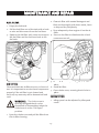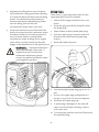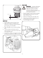
1
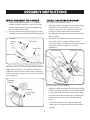
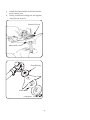
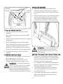
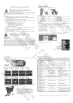
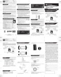
Safe Operation Practices Set-Up Operation Maintenance Service Troubleshooting OPERATOR’S MANUAL Brushcutter XT143/XT133 WARNING READ AND FOLLOW ALL SAFETY RULES AND INSTRUCTIONS IN THIS MANUAL BEFORE ATTEMPTING TO OPERATE THIS MACHINE. FAILURE TO COMPLY WITH THESE INSTRUCTIONS MAY RESULT IN PERSONAL INJURY. 769-07051 Thank You Thank you for purchasing a Brushcutter manufactured by MTD Asia. It was carefully engineered to provide excellent performance when properly operated and maintained. Please read this entire manual prior to operating the equipment. It instructs you how to safely and easily set up, operate and maintain your machine. Please be sure that you, and any other persons who will operate the machine, carefully follow the recommended safety practices at all times. Failure to do so could result in personal injury or property damage. All information in this manual is relative to the most recent product information available at the time of printing. Review this manual frequently to familiarize yourself with the machine, its features and operation. Please be aware that this Operator’s Manual may cover a range of product specifications for various models. Characteristics and features discussed and/or illustrated in this manual may not be applicable to all models. MTD Asia reserves the right to change product specifications, designs and equipment without notice and without incurring obligation. If you have any problems or questions concerning the machine, phone a authorized MTD service dealer or contact us directly. MTD’s Customer Support telephone numbers, website address and mailing address can be found on this page. We want to ensure your complete satisfaction at all times. Throughout this manual, all references to right and left of the machine are observed from the operating position. Table of Contents Safety Instructions .................................................. 3 Symbols .................................................................... 5 Get to know your brush cutter .............................. 7 Assembly Instructions ............................................. 8 Fuel and Oil Instructions .............................................10 Notes .......................................................................................... 20 Operating Instructions .................................................................... 11 Maintenance and Repair ................................. 13 Cleaning and Storage ................................................ 16 Troubleshooting .................................................... 17 Specification .................................................................... 19 Packing List ...................................................................................22 Record Product Information Before setting up and operating your new equipment, please locate the model plate on the equipment and record the information in the provided area to the right. You can locate the model plate by standing at the right side of the brush cutter and looking down at the end of the shaft tube. This information will be necessary, should you seek technical support via our web site, Customer Support Department, or with a local authorized service dealer. M ODEL NUMBER □□□□□□□□□□□ S ERIAL NUMBER □□□□□□□□□□□ Customer Support Please do NOT return the machine to the retailer or dealer without first contacting our Customer Support Department. If you have difficulty assembling this product or have any questions regarding the controls, operation, or maintenance of this machine, you can seek help from the experts. Choose from the options below: ◊ Visit us on the web at www.mtdproducts.com ◊ Call a Customer Support Representative at (512) 6289-1900 Extension 5691 ◊ Write us at No.18 RuiPu Road EPZ B,Suzhou Industrial Park,Jiang Su Province,PRC 215121 -2- SAFETY INSTRUCTIONS 1. Read, understand, and follow all instructions on the machine and in the manual before attempting to assemble and operate. Make sure you are familiar with all controls and their proper operation. 2. Keep this manual in a safe place for future and regular reference and for ordering replacement parts. 3. Never allow children or adults who have not been properly trained to operate this machine. 4. Make sure that you know how to stop the machine and disengage it quickly. 5. Check and inspect the unit before using it. Replace damaged parts. Check whether fuel is leaking. Ensure that all connections secured. 6. Whenever it is possible, clean the working area from all foreign objects such as stones, metal wire, or broken glass which could be ejected or become tangled in the rotating parts. These objects could be dangerous for yourself or bystanders or may cause damage to the machine. 7. The area around the operator with a radius of 15 meters is considered to be the dangerous ǤǤ ơ immediately if anyone enters the dangerous zone. 8. The brush cutter is designed for cutting grass, shrub and small tress only. Never use it for any other purpose. ͝Ǥƪ ǡ medication. ͕͔Ǥ ǡ Ƥ goggles, earplugs, gloves, and work shoes. 11. Never start or use this machine indoors or in a poorly ventilated area. Engine exhaust contains carbon monoxide, an odorless and deadly gas. It is harmful to your health. 12. Before starting the machine, make sure the rotary spool head or blade won’t touch the ground and/or any obstacles. 13. Working on wet lawn is very dangerous. Slipping while operating this machine may injure you. Remember to shut down the machine immediately once you feel unstable. 14. Never operate this machine without good visibility or light. Always be sure of your footing ƤǤ ͕͙Ǥǡ ơ immediately. Vibrations are always a warning sign. ͕͚Ǥƫ Ǥ Ǥ 17. After shutting down the machine, do not put it on the ground until the rotary blade is stopped. -3- 18. The rotary spool head and/or the cutting blade may keep running for a short time just after your shutting it down. Always be aware of the rotating parts; they are dangerous. If the cutting attachments cannot stop at idling, you should adjust the carburetor. 19. Never use parts, accessories or attachments which are not authorized for this unit. Otherwise, the user may be seriously injured and/or the unit damaged and the warranty may be deemed null and void. 20. If situations occur which are not covered in this manual, please contact MTD customer service department or your nearest local dealer. -4- SYMBOLS SAFETY AND WARNING SYMBOL Indicates danger,warning or a reason to be cautious.Can be used together with other symbols or pictograms. READ OPERATING MANUAL Non-compliance with the operating instructions and precautions may result in serious injuries.Read the operating manual before starting or operating the unit. WEAR EYE AND EAR PROTECTION CAUTION: Ejected objects may cause serious eye injuries and excess noise may cause loss of hearing.When operating the unit,wear eye and ear protection. KEEP BYSTANDERS AWAY CAUTION: All bystanders,especially children and pets,must be kept at least 15m from the working area. PETROL Always use clean and fresh lead-free petrol for mixing petrol. OIL Use only authorised oil according to the operating manual for mixing petrol. EJECTED OBJECTS AND ROTATING PARTS MAY CAUSE SERIOUS INJURIES CAUTION: Do not use the unit if the protective housing has not been correctly positioned for cutting.Keep away from the rotating line coil. -5- IGNITION SWITCH START IGNITION SWITCH RUN IGNITION SWITCH OFF/STOP BEWARE OF HOT SURFACES ƫ ǡ Ǥ Ǥ Ǥ ơǤ SHARP BLADE CAUTIONǣǤǡ Ǥ ͕ǤǤ ͖ǤǤ ͗Ǥ MAXIMUM RPM 9000 Ǥ -6- Get to know your Brush Cutter ơ Spark Plug Cap Starter Handle Harness Bracket Ignition Switch Throttle Lockout Throttle Cable Choke Lever Throttle Trigger Fuel Tank Air Filter Cover Throttle Cable Collector Hip Pad U-Handle Clamping Bracker For Cutting Attachment Shield Gear Case Handle Locking Knob Shaft Tube Cutting Attachment Shield Trimmer Head -7- ASSEMBLY INSTRUCTIONS INSTALL AND ADJUST THE U-HANDLE INSTALL THE TRIMMER HEAD 1. Put the U-handle between the top and middle clamps, and then connect the top, 1. Align the shaft bushing hole with the locking middle and bottom clamps by tightening rod slot in the protective cover and the the handle locking knob. notch in the gear case, and then insert the locking rod into these three holes/slots. 2. You can adjust the operating angles of the Holding the locking rod to ensure the output handle by loosening the handle locking knob. shaft in place. Handle Locking Knob 2. Ensure the threads of the trimmer head and the center of the output shaft are in line with each other, and then rotate the trimmer head anticlockwise until it is securely tightened. Protective Cover Shaft Bushing Top Clamp Shaft Tube Middle Clamp Bottom Clamp INSTALL THE CUTTING ATTACHMENT SHIELD Align the two holes on the cutting attachment shield with the other two holes in the clamping bracket, and then use the two screws to connect them together. Output Shaft Clamping Bracket Cutting Attachment Shield INSTALL THE CUTTING BLADE 1. Align the shaft bushing hole with the locking rod slot in the protective cover and the notch in the gear case, and then insert the locking rod into these three holes/slots. Holding the locking rod to ensure the output shaft in place. 2. Install the blade to the output shaft and make sure it contacts closely with the shaft busing. -8- 3. Install the blade holder and blade holder cover one by one. 4. Finally, install the locking nut and tighten it by the hex wrench. Protective Cover Blade Holder Cover Shaft Bushing Blade Holder Locking Nut -9- FUEL AND OIL INSTRUCTIONS OIL 1. Only use high quality air cooled 2-stroke engine oil. Never use water cooled engine oil or any oil for 4-stroke engine. Fuel 1. Always use fresh, clean lead-free fuel. Minimum octane number: 90. Mixing Ratio 1. Recommended mixing ratio of fuel and oil is 25:1. Warnings ͕Ǥƪ Ƥ the fuel tank with the mixture. 2. Do not mix the fuel and oil directly in the fuel tank; always use the mixing tank to do this job. ͗ǤƤ Ǥ immediately. 4. Move the unit 5 meters away from the fueling source and site before starting the engine. 5. Never use fuel which has been stored for longer than 30 days. That may bring damage to the unit, especially for the carburetor or the engine. - 10 - OPERATING INSTRUCTIONS STARTING COLD ENGINE WARNING : Before starting the engine, keep the cutting attachment clear of everything around it. 1. Use the mixing tank to mix the fuel and oil. Fill fuel tank with the mixture. See “Fuel and Oil Instructions”. 2. Press and hold the throttle trigger and throttle lockout at the same time, meanwhile use the other hand to push the ignition switch to the “START” position. 7. While holding the starter handle in right hand. Gently pull the starter rope out until you feel that the pawls hook onto the ƪǡ Ǥ 8. Repeat several times until the engine starts. 9. Move choke lever to “HALF OPEN” position. Allow the engine to run for 1-2 minutes to ơ temperatures. Note : Unit is properly warmed up when engine accelerates without hesitation. 3. Release throttle lockout, throttle trigger and ignition switch one by one. 4. Fully press and release the primmer bulb fo for 10 times. Some amount of fuel should be visible in the primer bulb and fuel lines. 5. Move choke lever to the “CLOSE” position. h engine i iis warmed d up, place l h choke h k Once the the lever to the “Full Open” position. Press throttle trigger to release throttle lock out. The ignition switch will automatically switch to normal running position, and the engine will run at idling speed. 6. Hold the unit with your left hand and press it against the ground. - 11 - Half open Full open Close Choke Lever SHOULDER HARNESS 1. Wear the harness on the shoulder then your stature until you feel comfortable with it on. 2. Attach harness hook to a suitable suspension point on the harness bracket according to Ƥ Ǥ unit gets a good balance before operating. STARTING WARM ENGINE 1. Push the ignition switch to the “START” position 2. Move the choke lever to the“HALF OPEN” position. 3. Hold the unit in left hand and press it against the ground. 4. While holding the starter handle in right hand. Gently pull the starter rope out until you feel that the pawls hook onto the ƪǡ Ǥ WARNING : Ǧ 5. Repeat several times until the engine starts. 6. Move the choke level to the“Full Open” position. mechanism on the harness to free of emergency. STOPPING INSTRUCTIONS SETTING THE LENGTH OF THE CUTTING LINE 1. The trimmer head releases the line without Ǥǡƪ tap the trimmer head on the ground while operating the unit at high speed. 2. The cutting line should always have the max. WARNING : Move the choke lever Ǥ ǡ to the “CLOSE” position if the engine ƥ Ǥ can not be shut down by the two ͗Ǥ ơ ǡ which automatically removes any excess after the machine becomes cold or line that is released. contact the authorized dealer for help. ͘Ǥ ơ which automatically removes any excess line that is released. ͕Ǥǡ the idling engine to cool down. 2. Move the ignition switch to the “OFF” ơǤ - 12 - MAINTENANCE AND REPAIR FUEL FILTER 1. Empty the fuel tank. ͖ǤƤ Ǥ ͗Ǥ Ƥ Ƥ fuel tank. ͖ǤƤ ƪ ǡ Ǥ ͗Ǥ ƤǤ ͘ǤƤ Ǥ Ǥ ͙Ǥ ǡ Ǥ Ƥ͕͔ ͚ǤƤǤ Ǥ ͛Ǥ ǡ ǤƤ Ǥ ǡ CARBURETOR Ǥ ͕Ǥ Ǧ WARNING : Ǥ Dzdz Ǥ AIR FILTER ͕Ǥ Ƥ ƤǤ - 13 - 2. Adjusting the idle-speed screw clockwise will increase the idling speed and adjusting it counterclockwise will decrease the idling speed. You should use a tachometer to measure the speed while adjusting. Make sure the idling speed within the recommended range 2800~3200 rpm. SPARK PLUG After every 25 operating hours take out the spark plug and check its condition. ͕Ǥ ơ down. ͖Ǥ Ƥ the spark plug. 3. Every unit had been run and tested at the factory to ensure that the carburetor works ͗ǤơǤ 4. Unscrew spark plug in counterclockwise at its best condition. But after a period of direction with the attached spark plug use, if trimmer head or cutting blade wrench. continues to rotate at idling or the engine stops when you fully release the throttle ͙Ǥơ Ǥ trigger, make adjustment to idle-speed screw. WARNING : Improper adjustment may cause damage to the unit. If engine does not run well after carburetor adjustment, please contact the authorized dealer where y bought g the p you product. 6. Check and adjust spark plug gap to 0.6-0.7 mm. 7. Screw in the spark plug and tighten to a ͕͘Ǧ͕͛ȈǤǤ 8. Re-attach the spark plug cap. 9. If spark plug is damaged or the unit still cannot work well after cleaning, replace with a new one. 10. To ensure the machine work well Please use ƤǤ - 14 - GEAR CASE WARNING : Improper adjustment may cause damage to the unit. If engine does not run well after carburetor adjustment, please contact the authorized dealer where you bought the product. MUFFLER 1. Stop the engine to check if there is enough lubricating grease in the gear case after every 25 hours of use. 2. Remove the oiling bolt on the gear case. 3. Replenish good quality lithium grease as ǡƤǤ 4. Screw and tighten the bolt. ͕Ǥ ƫ͖͙Ǥ 2. Make sure the unit is cool before any inspection or cleaning, otherwise you may ƫǤ ͗Ǥơƫ ǡ Ƥ bolt. ͘Ǥ carbon deposits or other stain. Clear away with applicable tools. ͙ǤƫƤ Ƥǡƫ Ǥ Ƥǡƫ Ǥ - 15 - CLEANING ͕Ǥơ Ǥ STORAGE ͕Ǥƪ Ǥ ͖Ǥ Ǥ ͗ǤǡǦ Ǥ Ǥ LONG-TERM STORAGE ͕Ǥ ͖ǦǤ ͔͗Ǥ ͖ǤǤ Ǥ ͗Ǥ Ǥ͔͗ Ǧ Ǥ Ǥ Ǥ :ǡ Ǥ ͕Ǥ Ǥ ǡ ǡ ǡǤǦ ǤǤ ͖ǤǡǦ Ǥ Ǥ TRANSPORTATION ͕Ǥǡ Ǥ ͖ǤǤ Ǥ ͗Ǥơ Ǥ ͘Ǥ Ǥ Ǥ - 16 - TROUBLE-SHOOTING Problem Cause Remedy 1. Spark plug wire disconnected. 2. Ignition switch set to OFF. 4. Stale or improperly mixed fuel mixture. plug. 6. Clean or adjust the gap. 7. Slowly and fully depress the primer 8. Squeeze the throttle and pull the adequately. starter rope with the choke lever in the 8. Flooded engine. operating position. 1. Dirty air/oil Ƥlter. 2. Stale or improperly mixed fuel mixture. 3. Incorrectly gapped or dirty spark plug. Engine does not idle mixture. bulb 10 times. 7. Primer bulb not depressed constantly at no load 4. Empty the tank and Ƥll with fresh fuel 5. Clean or replace Ƥlter. 5. Dir ty air Ƥlter/oil Ƥlter. 6. Incorrectly gapped or dirty spark Engine does not run 2. Set switch to ON. 3. Add fuel. 3. Fuel tank empty. Engine does not start 1. Reconnect wire. Improper carburetor adjustment 1. Clean or replace Ƥlter. 2. Empty the tank and Ƥll with fresh fuel mixture. 3. Clean or adjust the gap. Adjust ac cording to the manual or turn to an authorized service dealer for help. 1. Clean or replace Ƥlter. 1. Dirty air/oil Ƥlter. 2. Throttle wire disconne cted. Engine does not 3. Defective throttle control lever. accelerate 4. Incorrectly gapped or dirty spark plug. 5. Improper carburet or adjustment - 17 - 2. Reconnect throttle wire. 3. Replace the throttle control lever. 4. Clean or adjust the gap. 5. Adjust according to the manual or turn to an authorized service dealer for help. Problem Cause Remedy 1. Spool head or blade entangled with Engine has no power or stops duri ng cutting grass. 1. Stop the engine and clean the cutting attachment. 2. Clean or replace the filter. 2. Dirty air/oil filter. 3. Stale or improperly mixed fuel mixture. 4. Improper carburetor adjustment 3. Empty the tank and fill with fresh fuel mixture. 4. Adjust according to the manual or turn to an authorized service dealer for help. If further assistance is required, pleasecontact your authorized service dealer. - 18 - SPECIFICATION Specification XT143 XT133 Engine: Displacement: Carburator: Clutch Type: Starter: Max. Power: Reduction Ratio: Mixing Ratio(Fuel/Oil): Idel Speed: Speed at Max. Torque: Speed at Max. Power: Max. Cutting Speed: Trimmer Head Cutting Diameter: Diameter/Length of Cutting Line: Blade Cutting Diameter: Thickness of Blade: Diameter of Shaft Tube: Fuel Tank Capacity: Harness: Net Weight: Pakage Size: Air cooled 2-stroke engine 42.7cc Diaphragm Centrifugal Recoil 1200W 4:3 25:1 2800~3200RPM 6500RPM 7500RPM 9000RPM Ø 420mm Ø 3mm/3m Ø 255mm 2mm Ø 28mm 1.1L Deluxe/Loop 8.4Kg 183x29x30/11cm Air cooled 2-stroke engine 32.6cc Diaphragm Centrifugal Recoil 1050W 4:3 25:1 2800~3200RPM 6500RPM 7500RPM 9000RPM Ø 420mm Ø 3mm/3m Ø 255mm 2mm Ø 28mm 0.9L Deluxe/Loop 7.7Kg 183x27x28.5/11cm - - NOTES - 20 - - 21 - PACKING LIST Description 1. Main Unit˄Including U handle˅ 2. Deluxe Back Pack Harness 3. Cutting Blade 4. Cutting Attachment Shield 5. Trimmer Head (Instruction Attached) 6. Manual 7. Warranty Card 8. Mixing Tank 9. Accessory Bag 9.1 Safety Glasses 9.2 Goggle 9.3 Loop Harness 9.4 Ear Plug 9.5 Tool Bag 9.5.1 Spark Plug Wrench 9.5.2 Screwdriver 9.5.3 Inner Hexagon Wrench - - Qty. 1 1 1 1 1 1 1 1 1 1 1 1 1 1 1 1 2