1
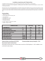
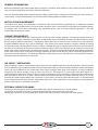
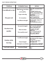
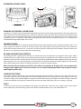
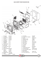
Glás
Non Boiler Insert
Installation & Operating Instructions
Table of content
1.
2.
3.
4.
5.
Page no:
Technical data. . . . . . . . . . . . . . . . . . . 1/2
General Information . . . . . . . . . . . . . . . . . 3/6
Installation Instructions. . . . . . . . . . . . . . . .
7/8
Operating Instruction. . . . . . . . . . . . . . . . . 9
Exploded View/ Parts Listing. . . . . . . . . . . . . . .
10
Technical Data:
STOVE DIMENSIONS
Front View
Left View
Top View
512 mm
596 mm
396 mm
494 mm
494 mm
186 mm
311 mm
239 mm
Firebox Dimensions
398 mm
1
Installation introduction with Technical data
Installation of a Pierce Stove must be in according to local codes and regulations in each country.
Installers must observe all local regulations, including those which refer to national and European standards when
installing the product.
All Pierce Stoves are accompanied by Both an installation manual with technical data and a manual on general use and
maintenance. Only after a qualified inspector inspects an installation, it can be used. All Pierce Stoves have a name plate
of heat -resistant material affixed. Information about identification and documentation for the product is contained on
this.
Technical data:
1. Material: Cast iron
2. Finish: High-temp, Resistance paint
3. Fuel: Multi-Fuel
4. Log length, max: 30cm
6. Flue outlet: Top rear
7. Flue pipe dimension:
8. Inside: 150 mm/175 cm2 cross section
9. Approx. weight: 74.5kgs
TECHNICAL DATA
Wood Logs
Ancit
Total Efficiency %
78.5 75.7
Nominal heat output kW 4.7 5.0
Mean CO emission (at 13 % O2) %
0.28 0.18
Mean flue gas temperature ºC
295
306
Flue gas mass flow
g/s 3.6 4.0
Mean CnHm emission
Nmg/m3 509
Mean NOx emission Nmg/m3 35
DIN Plus particulates Nmg/m3 35
Technical data according to EN13229
Operational mode: Intermittent
Recommended chimney draught: 12 Pa
Intermittent combustion in this context means normal use of the fireplace, i.e. fuel is added as soon
as the fuel has burnt down.
2
GENERAL INFORMATION:
Before installation of your Pierce Stove these instructions should be read carefully to fully understand the controls of
your new stove. Keep these instructions for future reference.
Due care should be taken when unpacking and installing a Pierce Stove as not to cause damage to your new stove or its
surroundings. Check all components are present and functioning before installation occurs.
INSTALLATION REQUIREMENTS
Installation must always be completed in accordance with current building regulations by a competent qualified
person. Incorrectly installed stoves can cause serious accidents such as chimney fires or damage to insulation materials
in partition walls and or roofs and ceilings. The installation of the stove to current building regulations is the sole
responsibility of the home owner.
CHIMNEY REQUIRMENTS
Do not install a Pierce Stove into a chimney that serves any other heating appliance. The chimney height must be a
minimum of 4.5 meters vertically from the floor on which the stove is installed to the top of the flue terminal in order
for the stove to perform satisfactorily. The chimney should not have an excessive cross sectional area and should be
in good condition without any cracks or blockages. The advice of an expert should be sought in relation to having
the chimney lined, if deemed necessary by an expert a suitable lining for a solid fuel stove must be used. The internal
diameter of any chimney or flue liner used must not be less than 125mm. Any flue liner and or adaptors used must be
fitted strictly to the manufacturer’s installation instructions. The flue should be checked and swept before connection
to the stove. There may be a need to fit a draught stabilizer if an excessive draft exists, advice should be sought from an
expert on the draft conditions. The chimney should be swept twice per year, any flue liner used should be cleaned in
accordance with manufacturer’s instructions.
AIR SUPPLY / VENTILATION
When installing a stove it is recommended that a permanent air vent be fitted if not already in position. The vent should
have an effective area of 550mm2 per kW of rated output above 5kW. In some instillation conditions under 5kW output
stoves will have sufficient air for combustion from natural draughts from doors and windows. In newer properties
designed to be almost airtight it may be necessary to have a vent fitted for a stove under 5kW rated output. It is
recommended to seek expert advice on the air supply/ventilation for your installation to achieve the best performance
from your Pierce Stove. If an air vent is fitted it must not be obstructed for any reason when the stove is in use. An
extractor fan should not be fitted in the same room as your stove as fumes may emit into the room. It is recommended
to fit a Carbon Monoxide alarm for your safety where you have a stove Installed; this is not mandatory in the republic of
Ireland at present but is mandatory in the UK.
EXTERNAL SURFACE CLEANING
Cleaning on the matt finish stove is recommended with a brush attachment on a vacuum cleaner.
Cleaning on an Enamel finish stove is recommended with mild soapy water and a soft cloth.
Strong abrasive utensils or strong detergents should never be used, always clean the stove after cooling.
3
DISTANCE TO COMBUSTIBLES
Pierce Stove insert stoves operate at high temperatures and are designed for installation into an existing fireplace.
For safe operation of your Pierce Stove there are minimum distances to combustible materials, including wood and
Plaster board, that must be adhered to at all times. These distances are as follows (see below diagram also)
350mm to either side of the stove
550mm above the stove
550mm from the front of the stove
If a combustible mantelpiece hangs further than 100mm from the fireplace front it is necessary to extend the minimum
distance above the stove by adding the extra amount to the minimum distance above the stove. For example if a mantle
protrudes 150mm, the clearance to the mantle will increase to 600mm. (550mm +50mm)
100
550
350
If the installation is into a recess in a studded wall (timber beams and plasterboard) then the following minimum
distances should be observed;
400mm on either side or rear
600mm above the stove
The stove should also be installed on a solid non combustible base, this base should extend 350mm from the front of
the stove as per above diagram.
GLASS CLEANING
When there is sufficient heat generated from the fire the air wash system should keep the glass clean. Over time the
glass may require cleaning, it is recommended to clean with a liquid detergent and soft cloth taking care not to scratch
the glass.
4
CHIMNEY FIRE
It is unlikely you will ever experience a chimney fire if your stove is installed and operated correctly as per the operation
instructions. In the unlikely event of a chimney fire close the primary air and secondary air controls immediately, evacuate
the building and call the Fire Service. Do not re-enter the building until you have been advised by the Fire service that
it is safe to do so. Ensure the stove is not used again until the chimney has been swept and the stove, chimney and flue
have been inspected by a qualified competent person.
IMPORTANT INFORMATION
1. This appliance should not be used as an Incinerator.
2. Non recommended fuels, including liquid fuels should not be used.
3. This appliance, especially surfaces, will be hot to touch when in operation and due care
should be taken. It is recommended to use an appropriate fire guard when children the aged
or infirm are present.
4. No unauthorized modifications should be made to this appliance.
5. Only recommended replacement parts from the manufacturer should be used for this
appliance.
5
FAULT FINDING INSTRUCTIONS
Problem
Fire difficult to start
Probable Cause
Wood green, too damp
or
poor quality
Logs are too big
Fire goes out
Air starvation
Insufficient draught
Action
-Use the recommended
fuel.
-To light the fire, use
small, very dry kindling.
To maintain the fire, use
split logs.
-Open primary air
and secondary air
-Check that the flue is not
obstructed, sweep it if
necessary
Seek specialist advice.
-Ensure that the primary
air is closed. Partially
close secondary air.
-Install a draught
stabiliser.
-Do not continuously
burn small wood or
carpentry offcuts.
-
Too much draught
Fire burns too
quickly
Excessive draw
Poor quality wood
Insufficient draught
Smokes while
burning
Low heat output
Down draught
Inadequate ventilation
Incorrect fuels
-Check that the flue is
not obstructed, sweep if
necessary.
Install an anti-down
draught cowl.
-Insure there is adequate
ventilation from outside
-Use the recommended
fuel.
6
INSTALLATION INSTRUCTIONS:
Step 1
Open the stove door and remove all loose packed parts, ashpan, tools and accessories.
Step 2
Disassemble the internal parts in the following order.
1. Fire Fence
2. Left and Right Side Castings
3. Loose Top Baffle
4. Grate (Riddling bar will need to be removed also)
5. Back Wall
6. Grate Support
1. Fire Fence
2. Side Castings
3. Loose Baffle
4. Grate
5. Back wall
6. Grate Support
2. Side castings
3. Loose Baffle
1. Fire Fence
6. Grate support
5. Back Wall
4. Grate
Step 3
Remove the stove from the convection chamber (Part18 in parts listing) by removing the 2no M6 fixing bolts under the
rear of the grate support.
Step 4
Ensure the opening is suitable for fitting the stove by placing the convection chamber into the recess in the fireplace
opening to ensure a good fit. Ensure the floor area is level with the hearth and there is no rocking as the insert Stove is
screw fixed to the floor.
Step 5
If the fit of the convection chamber is good and the base where it is to sit is level with the hearth proceed to fix the
convection chamber to the floor with the fixing screw supplied. This will require marking where to drill the hole with
the convection chamber in place, removing convection chamber, drilling hole and re inserting the convection chamber
into the fireplace recess and fixing it into place with the fixing provided.
7
Step 6
Lift the still disassembled stove into the convection chamber approximately 50mm, lift the front edge to prevent
damage to the hearth then slide it gently home to its final position
.
Step 7
The flue liner can now be fixed to the spigot (part 13 in parts listing) with the fixings provided and sealed according to
the manufactures instructions.
Step 8
Secure the stove to the convection chamber with the 2no M6 bolts removed in step 3. Before fully tightening push the
stove against the fireplace.
Step 9
Re assemble the parts removed in step 2 in reverse order.
Step 10
Re insert the ashpan under the grate.
Allow enough time for any fire cement and or mortar used in the installation to dry out according to the manufactures
instructions. Before lighting the stove check;
1. That all the internal parts are reassembled correctly.
2. That the riddling grate, primary air slider and air wash slider are working correctly.
3. That the connection between the stove and the flue liner/Chimney are fully sealed and airtight.
A small fire may then be lit to check the installation of the stove.
Wait at least 24 hours before running the stove at full output.
Please note;
When this stove is properly installed it will not emit any fumes into the room. On occasion when using the riddling
grate or refueling the stove a small amount of fumes might escape into the room. Constant fume emission is
dangerous. If there is persistent fume emission into the room open the windows and doors and let the fire go
out. Check the chimney/flue for any blockages and have them cleaned if necessary. Do not relight the stove until
the cause of the fume emission has been ascertained and corrected, get expert advice if necessary.
OPERATING INSTRUCTIONS:
8
OPERATING INSTRUCTIONS:
+
-
-
+
PRIMARY AIR CONTROL SLIDER VALVE
The primary air control slider is positioned underneath the ashpan door (see diagram above left). This slider controls the
intake of primary air underneath the grate, slide to the right to increase the rate of burn and to the left to decrease the
rate of burn. This slider should be fully open (to the right) when lighting the stove. When the stove is in use this control
can get hot and it is advised to use the glove provided with your stove when adjusting. Primary air is normally used
more when burning mineral fuels such as coal.
AIR WASH SLIDER
The air wash slider control is positioned underneath the door to the top of the stove (see diagram above centre). This
slider controls the intake of air wash air into your stove, slide to the right for the maximum amount of air and to the
left for the minimum amount of air. Over time you will find the best setting for you installation and type of fuel used.
Airwash air is normally used more when burning wood logs.
RE-FUELLING/RIDDLING CONTROL
The riddling control is positioned to the left just above the ashpan compartment (see diagram above right). Before
refueling the stove riddle the fire by connecting the operating tool supplied onto the riddling control and slide the
control in and out to release all the dead ash to the ashpan compartment below. When adding more fuel do not over
fill the fire box as this can cause damage by over firing the stove, the fuel should not be filled higher than the front fire
fence. After fueling close the door and adjust the primary air slider to required setting.
Never let the ash pan become over full as this will cause damage to the grate. Be sure to empty the
ashpan before lighting the stove. Ensure the ash has cooled completely before removing the ashpan
and disposing of the ash.
LIGHTING THE STOVE
First make sure the inside of the stove has been adequately cleaned and that all dead ash has been removed also
ensure the ashpan has been emptied and the ashpan compartment is clear of any dead ash. Open the primary air to its
maximum setting. Place some firelighters or papers on the centre of the grate and light, add some kindling as required,
as the fire establishes itself add your selected fuel and close the door. Adjust the primary air setting as required.
FUELS
The stove has been tested using smokeless fuel (Ancit) and wood logs. Other fuels are available and may give similar
results. Wood logs up to 30cm long can be used. All fuels should be kept as dry as possible before Use.
9
GLAS INSERT STOVE EXPLODED VIEW
1. Fire Fence
PS10120
2. Ash Baffle
PS10162
3. Ashpan Door PS10108
4. Fire door
PS10107
5. Front Frame PS10103
6. Top Baffle
I1141
7. Right Baffle
I1113
8. Left Baffle
I1112
9. Moving Grate I1115
10. Grate Frame I1114
11. Back Baffle
I1111
12. Air Wash Cover I1109
13. Spigot125
(2)
14. Ash Pan HandleCA0105A
15. Hinge A
CA1604
Hinge BCA1603
Hinge AxiaCA0614
16. Blanking Plate CA1102-B
17.Holder
CAWK0105
18. Convection Chamber
CAWK01
19. Axial Fiber 20. Combustion Chamber
21. Handle
22. Fiberglass rope
23. Fiberglass rope
24. Glass slips
25. Door Handle
26. Door Glass
27. Door Catch
28. T Handle
29.Ashpan
30.Wrench
31. Grate control handle
32. Air Wash control
33. Air wash Shutter (down)
34. Logo Badge
35. Door handle axel
36. air wash shutter (up)
CAL0103
CANK01
CA0114-083
CA0802
CA0801
CA1112
CA0114-083
CA10-PS101
CA1505
CA0109
CA1218
NLFBS-007
CA0137
CA0104-PS201
CA1114-PS101
CA0101-ZH
CA1113-PS101
10
Unit 2
Whitemill Industrial Estate
Wexford
Co Wexford
www.piercestoves.ie
Email: [email protected]