1
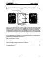
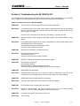
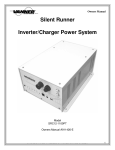
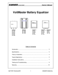
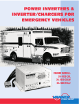
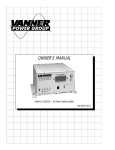
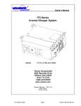
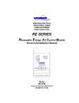
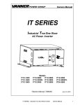
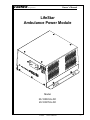
VANNER Incorporated
Owner’s Manual
LifeStar
Ambulance Power Module
Model
20-1050CUL-DC
20-1000TUL-DC
LifeStar
Owner’s Manual
-1-
VANNER Incorporated
Owner’s Manual
Table of Contents
Table of Contents ....................................................................................................... 2
Section 1 : General Installation Diagram................................................................... 3
Section 2 : Introduction.............................................................................................. 4
Section 3. Functionality ............................................................................................. 4
Inverter Function .................................................................................................. 4
Battery Charger .................................................................................................... 5
DC Power Output ................................................................................................. 5
Section 4: Specifications ............................................................................................ 6
Unpacking the Ambulance Power Module .......................................................... 7
Installing the Ambulance Power Module ............................................................ 7
Inverter Lamp Description ................................................................................... 9
Section 6: Installing the Inverter and Charger Remote Status Display Panels ....... 10
Section 7: Operating the 20-1050CUL-DC Ambulance Power Module ................. 11
Section 8: Troubleshooting the 20-1050CUL-DC................................................... 12
LifeStar
Owner’s Manual
-2-
Fault
Shore Power Input
Standby
ON
POWER INVERTER
Interior Mounted Display
Fuse
150A
OFF/RESET
ON
V
LifeStar
Owner’s Manual
R
OFF
ON
IN
E
E
B
R
A
T
TE
R
Y
O
V
R
W
E
LO
TE
V
P
O
M
E
R
LO
U
D
B
A
LK
/A
BS
R
12v
E 10 4 5 8 6
L IS T E D
6 8 U8
T
IN
1
-L
O
AD
P
TY
E
OFF
ON
55A
15A
G EL
TE
A
R
FLOOD
ON
2
3
1.
IG
INV/CHG
Ignition Interlock Switch
R
DC POWER
ER
W
SW P O
N
TE DC
IO
O
M
2v
E
R
+1
.
.
3
2
IT
N
ON
OFF
AC OUTPUT
DE S I G NE D I N A C CO RD AN C E W I T H
G SA F EDE RA L S PE CI F I C AT I O N
K KK - A- 1 8 22 F
1
W
O FF
S
Y
N
E
R
TE
G
IO
O
R
TE
IT
A
N
EM
H
AT
-C
- IG
-R
-B
4
5
3
REMOTE
2
EM
D
D
AN
12 0 VAC 6 0H z
Vehicle Ignition Switch, or
equal +12V Remote Switch
PO W ER I N V ER T ER
EM ER G E N C Y/ L AN D VEH I C L E
A
1 2 3 4 5
/M
N
CHARGER
Y
IO
D
T
A
P
E
R
O
B LI N K =S TA N DB Y / LO A D D E MA N D
S T EA D Y= I NV E RT E R ON
T
Experience Power... Experience Vanner.
LifeStar
1 2 V OL T D C PO W E R I N V ER T E R
BA T T E R Y C H A R G ER / C O N D I T IO N E R
A U T O M AT I C T R A N S F ER S W I T CH
SCALE:
NONE
REA/ECO NO.:
Fault
XXXX
THIS DRAWING AND ALL INFORMATION CONTAINED
HEREIN IS THE PROPERTY OF VANNER INC. AND MAY NOT
BE COPIED, REPRODUCED OR DIVULGED TO
UNAUTHORIZED PERSONS WITHOUT THE EXPRESS
WRITTEN CONSENT OF VANNER INC. IT IS PROVIDED
SOLELY FOR THE CONVENIENCE OF THE USER AND SHALL
BE RETURNED UPON REQUEST.
AC ON/
High Charge
AC ON/
Maint. Charge
CHARGE INDICATOR
Exterior Mounted Display
DRN\DATE
MEO
7-22-08
DATE
Interior Mounted DC
Service Lamp, ETC
REVISIONS
DESCRIPTION
ECO
CHK\DATE
XXX
XX/XX/XX
DRAWING/
PART NO.
TITLE:
SHEET
1 OF 1
REV
A
HILLIARD, OHIO USA
20-1050CUL-DC
Wiring Diagram
INCORPORATED
OFF
ON
Ground Remote ON/OFF Switch
TOL. UNLESS
OTHERWISE NOTED
.x ± .025
.xx ± .015
.xxx ± .005
REV
VANNER Incorporated
Owner’s Manual
Section 1 : General Installation Diagram
-3-
VANNER Incorporated
Owner’s Manual
Section 2 : Introduction
Thank you for purchasing a Vanner Ambulance Power Module for your emergency vehicle. We are
confident you will be satisfied with its performance.
Vanner products are designed and manufactured by skilled professionals using the highest standards in
workmanship, guaranteeing excellent performance and reliability for your emergency vehicle. With
minimum maintenance and care, you can expect years of trouble-free service from your Vanner product.
The 20-1050CUL-DC is a 12 VDC to 120 VAC inverter with a built-in battery charger/conditioner, transfer
relay and KKK Spec 12V Portable Equipment Charging Circuit. This unit is equipped with an AC line cord
for connecting AC input power (shore/utility power) and a receptacle with a Ground Fault Circuit
Interrupter (GFCI) for AC output. This enables you to plug AC loads directly into the inverter. The DC
cables have quick connectors to facilitate installation and pre-wiring of emergency vehicles. The 12V
Portable Equipment Charging Circuit has a spring clamp for ease of installation. The transfer relay is
powered by +12Vdc, the unit must be connected to the DC source for the transfer relay to work.
The 20-1000TUL-DC is a 12 VDC to 120 VAC inverter with transfer relay and KKK Spec 12V Portable
Equipment Charging Circuit. This unit is equipped with an AC line cord for connecting AC input power
(shore/utility power) and a receptacle with a Ground Fault Circuit Interrupter (GFCI) for AC output. This
enables you to plug AC loads directly into the inverter. The DC cables have quick connectors to facilitate
installation and pre-wiring of emergency vehicles. The 12V Portable Equipment Charging Circuit has a
spring clamp for ease of installation. The transfer relay is powered by 120VAC, the transfer relay will
engage without the unit being connected to the DC source.
This manual is written around the 20-1050CUL-DC, all sections of this manual that refer to the Charger
section of the unit does not apply to the 20-1000TUL-DC.
Section 3. Functionality
WARNING : Battery input cables must be connected to the battery with proper polarity to avoid
damaging the inverter.
NOTE : If the battery is fully charged at the time AC input is applied, the unit will go directly into Ready/
Maintenance mode.
Inverter Function
The 20-1050CUL-DC converts battery power to 1050 Watts of 120 VAC modified sine wave power to
operate vital emergency vehicle equipment. The unit is easily connected to the positive and negative
posts of a battery system with appropriate fusing, and when turned on, produces 120 VAC True RMS
voltage.
The inverter also has an energy-saving feature called Load Demand. With this feature, the inverter output
is pulsed, significantly reducing the current draw from the battery until a demand is made on its output.
Continuous output of 120 VAC resumes when a load greater than 20 Watts is applied. The load demand
feature can be disabled with the Setup Switch on the front panel.
A built-in transfer relay switches the AC output receptacle from the inverter to the AC input when the unit
senses AC input from the shore/utility power.
LifeStar
Owner’s Manual
-4-
VANNER Incorporated
Owner’s Manual
Battery Charger
The 20-1050CUL-DC Battery Charger's superior design incorporates a multi-stage charger. This design
enables the unit to automatically charge batteries, maintaining the battery's integrity and reducing the
likelihood of premature failure.
* Bulk Absorption Charge Mode
While in the Bulk Charge mode, the unit continuously charges at a constant current of 55 Amps (high
setting) this is the factory setting, or 15.0 Amps (low setting) The unit will charge until battery voltage
reaches 14.2 VDC for flooded battery setting, or 14.1 VDC for gel battery setting. The unit then supplies a
fixed voltage for one hour.
* Ready/Maintenance Mode
The charger automatically enters the Ready/Maintenance mode, maintaining the battery’s proper voltage
of 13.2 VDC for flooded battery setting, or 13.6 VDC for gel battery setting. This Ready/Maintenance
mode is designed to eliminate gassing (overcharging), helping to extend the life of the battery.
A Setup Switch is located on the front panel for selecting the type of battery (Flooded Lead Acid or Gel
Lead Acid), charger output current (High/Low), and Load Demand (On/Off).
Remote Control
Built-in remote control capability is provided for use with a customer supplied +12v signal and with a
customer supplied Ground signal. Either one, both or neither may be used.
To activate +12v remote control set the dip switch labeled IGNITION to the ON position. Connect the
+12v remote control signal wire to the compression terminal labeled IGNITION.
To activate GROUND control set the dip switch labeled REMOTE to the ON position. Connect the
GROUND control signal wire to the compression terminal labeled REMOTE.
If no remote control is required set both dip switches to the OFF position.
The unit can be used with the IFM1 Interface Module and is fully backward compatible for retrofitting
installations that already have the IFM1 Interface Module. To use the IFM1 set the dip switches labeled
IGNITION and GROUND to the OFF position. Plug the IFM1 modular cord into either 8-pin socket.
DC Power Output
The 20-1050CUL-DC DC Power Output complies with KKK section 3.7.7.2 for PORTABLE EQUIPMENT
CHARGING CIRCUIT. Which states “A circuit shall be furnished for charging all portable battery powered
devices, i.e. suction units, hand lights, portable radios, etc. This circuit shall prevent discharge of chassis
batteries by only permitting the charging of portable devices when the vehicle is either running or the
optional battery conditioner is connected to shore power. Circuit breaker protection shall be provided and
shall have a minimum 10 amp capacity. An additional tagged, identified lead shall be furnished in both the
cab and module for connection of additional (future) portable equipment that requires recharging.”
DC Power (battery power) is available while +12V Remote Switch Terminal is energized and while the
20-1050CUL-DC is in battery charger mode. DC output is protected by a 20A circuit breaker label “DC
Power”
LifeStar
Owner’s Manual
-5-
VANNER Incorporated
Owner’s Manual
Section 4: Specifications
Inverter
20-1050CUL-DC
Output at 120 VAC RMS (Continuous Power Rating)
Surge Capacity at 120 VAC (3 sec)
Input Voltage, VDC
(Deep Cycle Battery Recommended)
AC Output Voltage
20-1000TUL-DC
1050 Watts
2100 Watts
12 VDC, Nominal
10.5 VDC min, 16.0 VDC max.
120 VAC ± 5%
DC Current Draw (Battery)
OFF
In Load Demand
Full ON at No AC Load
Full On with Load
Frequency
Output Wave Form
0.017 Amps Typical
0.09 Amps Typical
0.7 Amps Typical
Approx. AC Load Watts ÷ 10
60 Hz ± 0.2%
Modified Sine Wave
Battery Charger
Charging Capacity (note “DC Source” section below)
Input Voltage
Input Current
Bulk Voltage
Float Voltage
55 Amps (High)
15 Amps (Low)
120 VAC ± 10%
12.0 Amps
14.2 VDC (flooded), 14.1 VDC
(gel)
13.2 VDC (flooded), 13.6 VDC
(gel)
N/A
N/A
N/A
N/A
N/A
Bypass Transfer
Output Current, GFCI Outlet
12 Amps
DC Source
Output Voltage
Battery Voltage
20.0 Amps Max. (Current must be subtracted from
“Charging Capacity” above)
Output Current
Other Specifications
AC Input Termination
AC Output Termination
Ambient Temperature
Cooling Air
Chassis
Dimensions
Weight
3ft. Line Cord
Duplex GFCI Receptacle
-20° to +110°F, -29° to +43.4°C
Fan Cooled
Aluminum
11.57”W x 5.94”H x 11.04”D
22 LBS
LifeStar
Owner’s Manual
-6-
VANNER Incorporated
Owner’s Manual
Section 5: Installing the 20-1050CUL-DC
Unpacking the Ambulance Power Module
Inspect the shipping container and equipment for loose or damaged parts. If any damage is found,
immediately notify the freight carrier.
Installing the Ambulance Power Module
1. Verify the inverter ON OFF/Reset switch is in the OFF position (The button should NOT be pushed
in.) Make sure power to the vehicle wiring harness is disconnected.
2. Select a location for the unit. An ideal installation location has the following characteristics:
• Close to the battery (not in the same enclosure)
• Protected from the weather
• Well ventilated
Air enters by the fan at the rear of the unit, and exits through the sides of the unit.
For maximum unit performance, avoid recirculating the same hot air through the unit.
3. Route DC input cables.
Route the negative and positive DC input cables from the inverter (through the quick connector) to the
battery. If required, protect cables where they contact hard, sharp edges.
DC Cable Length
Size (AWG)
2 AWG
1/0
Maximum Distance (FT)
12ft
20ft
4. Install inline fuse.
Install an inline fuse in the red, positive DC input cable between the battery and inverter,
within 18 in. of the battery or DC wiring bus system.
Vanner recommends using
Bussmann ANN-150 Fuse and #4164 Fuse Holder (Vanner P/N: 014838 Fuse and 03637 Holder) or
Feraz-Shawmut CNN-150 Fuse and #4164 Fuse Holder.
5. Connect bonding lug.
Use an 8AWG or larger copper conductor to connect the chassis bonding lug to the vehicle chassis.
6. Connect the inverter to the battery.
Connect the black, negative DC input cable from the quick connector to the battery negative (-)
terminal. This battery negative terminal is usually where the battery negative connects to the engine
block or frame. Connect the red, positive DC input cable from the quick connector to the in/line fuse
near the battery positive (+) terminal. This battery terminal is usually connected to the DC electrical
system at the battery side of the Battery Disconnect Switch.
7. Connect DC Power Source terminal to DC loads
Connect the output from the DC Power terminal on the front panel of the Inverter to equipment
locations on the vehicle, 20Adc max. Max wire size is 12AWG, use the supplied “Vanner” screwdriver
for this terminal.
8. Select Load Demand option.
Select Load Demand option if desired, using the proper switch position on the front panel Setup
Switch. With Load demand ON, the inverter conserves battery energy and operates only when a load
greater than 20 Watts is applied. (Factory setting is OFF).
LifeStar
Owner’s Manual
-7-
VANNER Incorporated
Owner’s Manual
9. Select battery type.
The charger is capable of charging both gel and flooded lead acid batteries. Select the battery type
using the Setup Switch on the front panel. (Factory setting is Flooded).
10. Select the charging rate. (20-1050CUL-DC only)
In the high position, the output capability is 55 Amps. In the low position, it is 15 Amps. Vanner
recommends the high position for all installations. The low charge rate can be used if there are NO
additional DC loads on the vehicle. (Factory setting is 55A)
11. Select remote control style(s) being used. Either one, both or neither may be used.
To activate +12v remote control set the dip switch labeled IGNITION to the ON position. Connect the
+12v remote control signal wire to the compression terminal labeled IGNITION.
To activate GROUND control set the dip switch labeled REMOTE to the ON position. Connect the
GROUND control signal wire to the compression terminal labeled REMOTE.
If no remote control is required set both dip switches to the OFF position.
The compression connector is designed to accept bare copper wire, 28 – 12 gauge, stranded or solid.
Each of the three positions consists of an upper actuator cavity and a lower spring-loaded wire clamp
cavity. Insert the tool provided with the CUL-DC, or a small flat screwdriver, into the upper area of the
actuator cavity. Gently lift the screwdriver handle UP which will open the spring-loaded clamp below.
Insert the bare wire into the upper area of the clamp cavity.
12. Connect the AC loads.
Connect the AC loads to the inverter GFCI receptacle. Any time AC power is applied to the AC input
(shore/utility power), it will pass through this GFCI receptacle.
13. Verify installation.
Verify all connections are tight and secure.
LifeStar
Owner’s Manual
-8-
VANNER Incorporated
Owner’s Manual
Inverter Lamp Description
Inverter
Light Action
Description
Steady Green Light
Inverter in On and Operating.
Inverter circuit is in Stand-by, Shore power is On and supplying AC power to the
AC loads. The Inverter will turn On and supply the load if shore power is lost.
Inverter circuit is in load Demand. Shore power is Off. The inverter is waiting for a
load greater than 20 watts.
Single Blink Green Light
Double Blink Green Light
Battery Low
Light Action
Description
Solid Red
Inverter is On and the battery is almost too low to operate the inverter.
The inverter is Off. The battery voltage dropped below 10.5 volts DC and the
inverter shut itself Off. The inverter On/Off switch must be cycled to reset the unit.
Blinking Red
Overtemp
Overload
Light Action
Description
Solid Red
The unit is Off. The unit has turned itself Off because it is too hot. This can be
caused by operating an AC load which is too large for the inverter, or lack of
ventilation. When the unit cools the inverter will start operating again.
Light Action
Description
Blinking Red
Solid Red
Charger
Bulk Absorption
Charger
Ready/Maint.
The inverter is On but overloaded. Reduce the AC load quickly or the inverter will
shut off due to the overload condition.
The inverter is Off. An overload has occurred and the inverter has shut off to
protect itself. Reduce the AC load, the inverter On/Off switch must be cycled to
reset the unit.
Light Action
Description
Blinking Yellow
The charger is operating. The batteries were low and in need of a charge. The
charger is in the process of charging the batteries to the bulk voltage. The
charging current is limited based on the position of the Charger High/Low switch.
Light Action
Description
Solid Green
The charger is operating. The batteries are near full charge and the charger is in
the maintenance mode. In this stage, the charger is holding the batteries at the
float voltage. The charging current is limited based on the position of the Charger
High/Low switch.
LifeStar
Owner’s Manual
-9-
VANNER Incorporated
Owner’s Manual
Section 6: Installing the Inverter and Charger Remote Status Display
Panels
Ø 0.110 (#35 Drill Bit) Hole (2 PLCS)
Ø 1.875 (1 7/8) Hole
Fault
CHARGE INDICATOR
2.22
3.015
AC ON/
Maint. Charge
Fault
POWER INVERTER
ON
1.11
AC ON/
High Charge
Fault
Standby
2.360
Remote Mounting
Pattern
There are two remotes available for the 20-1050CUL-DC, One for Inverter Status (Part Number – LSIR)
and the other is for Charger Status (Part Number – LSCR). Both the Inverter and Charger Remote Status
Display Panels contain a red and green LED indicator, On the charger status panel, a SOLID green light
indicates the presence of shore power or that the battery is being maintained at its current level. A
FLASHING green light indicates the presence of shore power and the charger is in high charge mode. On
the inverter status panel, the SOLID green indicator light signifies the unit is ON, a FLASHING light
indicates the unit is in the Standby mode. For both the remotes the red Fault LED indicator shows
problems such as over temperature, output overload, or low battery.
The panels have a gasket seal which will keep the electronics safe from weather and water spray. Each
panel is equipped with a RJ45 connector for easy installation and replacement. The following installation
procedure applies to both the inverter and charger panels:
Step 1: Select a location for the panel.
Identify the desired location for the inverter and/or charger panels.
Step 2: Route cable.
Carefully route the modular cable from the front of the LifeStar to the remote location. This cable does not
need to be shielded but it should be routed away from the AC cables.
Step 3: Secure panel to surface.
Remove the protective liner from the gasket and mount the panel using the provided #8 screws through
the two holes in the panel.
LifeStar
Owner’s Manual
- 10 -
VANNER Incorporated
Owner’s Manual
Section 7: Operating the 20-1050CUL-DC Ambulance Power Module
Use the following instructions to operate the 20-1050CUL-DC Inverter.
Step 1: Install the 20-1050CUL-DC Unit.
Completely install the inverter and charger using the instructions provided in Section 2 of this manual.
Step 2: Start the vehicle.
Step 3: Turn switches on.
Turn on the Module Disconnect Switch and the Inverter Remote Switch.
Step 4: Verify Power.
Apply an AC load, such as a shop light or drill. Verify operation.
Step 5: Apply shore power
Turn vehicle off, apply shore power to the 20-1050CUL-DC/Ambulance shore line connection. After shore
power has been connected one of the Chargers LED’s will light or flash. Push the ON-OFF/RESET
Inverter Switch to the ON position. The inverter lamp will flash, indicating that the inverter is standing by.
Step 6: Observe Transfer Switch.
Remove the shore line connection from the emergency vehicle. The unit will automatically switch to
Inverter mode and operate the AC load using battery power. When shore power is restored, the unit
examines the AC input for five seconds and then switches the loads back to run directly from AC shore
power.
LifeStar
Owner’s Manual
- 11 -
VANNER Incorporated
Owner’s Manual
Section 8: Troubleshooting the 20-1050CUL-DC
The following are the most common questions heard by Vanner service professionals. If your situation
does not apply to the following categories, please contact your local Vanner Inc Distributor.
Vanner Inc Customer Service: 1-800-AC-POWER
SYMPTOM
All of the LED’s on the front panel blink one at a time, in sequence.
SOLUTION
It is normal for this to occur if the inverter switch is On when the DC input is connected to
the unit. If the DC is already connected and the LED’s blink in sequence then the DC
input is dipping in voltage.
Check for poor connections in the DC wiring, bad battery, or a heavy DC load.
SYMPTOM
ON lamp flashes or does not light steadily after pushing in the ON-OFF/RESET Inverter
Switch.
SOLUTION
Lamp flashes when utility power is present. Lamp flashes in Load Demand Waiting mode.
Check/Reset GFCI on the receptacle.
Check battery connections if utility power is OFF
Check DC fuses if utility power is OFF
SYMPTOM
ON lamp fully illuminates. AC load does not run.
SOLUTION
Check and reset circuit breaker.
Check and reset GFCI
Verify AC load and cord is in proper condition.
SYMPTOM
BATTERY LOW lamp illuminates when AC load is applied.
SOLUTION
Check battery connections.
Check battery condition.
Recharge battery if voltage is less than 10.5 VDC.
Check the vehicle's alternator charging system for proper operation.
SYMPTOM
OVERTEMP lamp illuminates.
SOLUTION
Something has caused the unit to overheat. Check for obstruction of air flow to the
cooling fan or from ventilation holes. Verify AC load is within unit's rated capacity.
SYMPTOM
OVERLOAD lamp illuminates with AC load applied.
SOLUTION
Verify AC load is within unit's rated surge and continuous capacity.
SYMPTOM
DC fuse blows when connecting DC input cables.
SOLUTION
Check for reverse polarity: red cable to battery positive (+), black cable to battery
negative (-). The unit may be damaged and require repair service.
SYMPTOM
Low battery lamp glows dimly when inverter is off.
SOLUTION
This is normal.
LifeStar
Owner’s Manual
- 12 -
VANNER Incorporated
Owner’s Manual
Notes:
LifeStar
Owner’s Manual
- 13 -
VANNER Incorporated
Owner’s Manual
Vanner Incorporated
4282 Reynolds Drive
Hilliard, Ohio 43026
1-800-AC POWER
(1-800-227-6937)
Tel: 614-771-2718
Fax: 614-771-4904
www.vanner.com
e-mail: [email protected]
Part Number
D914588-F
4-2-2014 Printed in U.S.A.
LifeStar
Owner’s Manual
- 14 -