1
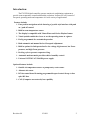
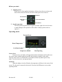
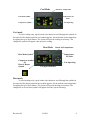
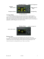
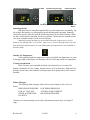
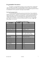
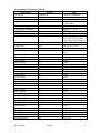
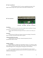
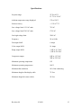
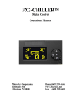
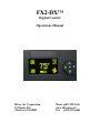
FX2-DX™ Digital Control Operations Manual Micro Air Corporation 124 Route 526 Allentown NJ 08501 Phone (609) 259-2636 www.Microair.net Fax (609) 259-6601 Introduction: The FX2-DX digital controller operates marine air conditioning equipment to provide room temperature control and humidity reduction. It allows for easy control of fan speed, operating mode and temperature in a wide variety of applications. Features include: Four position navigation switch featuring a joystick style interface with push on / push off control. Built in room temperature sensor. The display is compatible with Vimar Plana and Gewiss Playbus frames. Visual symbols enable the viewer to see the operating status at a glance. Easily programmed for customized operation. Both automatic and manual six level fan speed adjustment. Built in options for fault protection for low voltage, high current, low Freon pressure, and high Freon pressure. De-icing cycle to prevent evaporator icing. Automatic moisture mode provides relative humidity control. Universal 115/230 VAC 50/60 Hz power supply. Optional features include: Outside air temperature sensor or pump sentry water sensor. Alternate air sensor. DC fan control board featuring programmable speed control for up to four quiet DC fans. CAN (Computer area network) bus capability Revision: 04 9/24/09 2 Before you start: 1. Applying power: When power is first applied, the display will show the software revision, and then return to the last state the unit was in when power was removed. Up Button On/Off Button Mode Select Button Fan Control Button Down Button 2. Joystick operation: The four position joystick may be tapped up, down, right, left or in the center to make changes to the operation of the control. Gently tap this switch to operate it. Operating modes Screen Saver Room Temperature Cool Mode Symbol Compressor Symbol Fan Operating Screen Saver In screen saver, the display will appear dim and the information will scroll across the screen. Status symbols appear as needed and operation continues in the mode selected. Screen saver is activated after two minutes without any button press in any mode. To exit screen saver, just tap any button. Off Mode When the display is in the off mode, the temperature will show in the center of the screen. The fan may be operated in this mode. Press the On/Off button to access other operating modes. Revision: 04 9/24/09 3 Cool Mode Room Air Temperature Cool Mode Symbol Temperature Set Point Compressor Symbol Fan Operating Automatic Fan Mode Cool mode To select cooling only, tap the mode select button to scroll through the symbols in the top left of the display until the cool symbol appears. Set the desired room temperature by tapping the up or down button. The system will provide cooling as necessary. The compressor symbol will appear when system is cooling. Heat Mode Room Air Temperature Heat Mode Symbol Compressor Symbol Or Electric Heater Symbol Temperature Set Point Fan Operating Fan Speed Indicator Heat mode To select heating only, tap the mode select button to scroll through the symbols in the top left of the display until the heat symbol appears. Set the desired room temperature by tapping the up or down button. The system will provide heating as necessary. The compressor or electric heat symbol will appear when the system is heating. Revision: 04 9/24/09 4 Automatic Mode Automatic Mode Symbol Room Air Temperature Temperature Set Point Compressor Status Fan Operating Fan Speed Indicator Automatic Mode To select automatic mode, tap the mode select button to scroll through the symbols in the top left of the display until the automatic mode symbol appears. In this mode, the system will automatically maintain room temperature. Set the desired room temperature by tapping the up or down joystick button. When the system is operating, the appropriate symbol will appear in the lower left corner. Moisture Mode Room Air Temperature Moisture Mode Symbol Moisture Mode Select this mode to help control humidity in the room while the room is unoccupied. To select moisture mode, tap the mode select button to scroll through the symbols in the top left of the display until the moisture mode symbol appears. The control will operate in cooling mode for up to 1 hour every 6 hours. Revision: 04 9/24/09 5 Manual Fan Speed Low Fan Speed Indicator Animated Symbol Manual Fan Speed High M=Manual Fan Animated Symbol Fan Speed Indicator Fan Operation Button Operating the fan: Fan speed may be controlled automatically by room temperature or manually. Tap the joystick fan button to cycle through fan speeds and automatic operation. Manually selected fan speed is indicated with the M showing before the fan speed indicator. When the fan is automatically controlled, the M is not present. The fan may be controlled in the cool, heat, automatic modes as well as in the off state. Manual fan speed operation is not available when the compressor or electric heater is not running if the “Cycled Fan” option is set. Turn the unit off in this case and then manual fan operation may be used. Manual fan speed operation is not available in moisture mode. Outside Air Temperature If the optional outside air temperature sensor is installed, the temperature set point in the upper right of the display will alternate with OAT showing outside air temperature. Viewing System Status In the ON state, press and hold the Mode select button for two seconds. The display will indicate AC line voltage, System current, AC Line frequency, High and Low pressure switch status, and condenser coil temperature if the pump sentry water sensor is installed. Failure Messages The following fault messages will be shown on the display in the event of a failure. HIGH FREON PRESSURE LOW FREON PRESSURE LOW AC VOLTAGE SYSTEM OVER CURRENT* CHECK WATER PUMP AIR SENSOR TROUBLE LOCKOUT *System over current message occurs only with sustained current draw exceeding 35 amps. Revision: 04 9/24/09 6 Programmable Parameters: Descriptions of programmable parameters, factory default values, and allowable values are shown in two tables. Use programmable parameter table A for installations without the optional DC fan control board installed. Use programmable parameter table B for installations with the optional DC fan adapter board installed. Entering the program mode: To enter the program mode first put the unit in the off state. Press and hold the joystick in the center for 3 seconds. Use the fan button to advance to the next parameter and the mode button to go back to the last parameter. Use the up and down buttons to change the parameters value. Exit the program mode when finished by pressing and releasing the On/Off button or wait 60 seconds for the display to exit. Note: program mode can also be entered by pressing the following sequence of buttons: Mode, Up, Down, Mode in the off mode. Programmable Parameter table A Description Default Value Cycled fan Continuous Cycled or Continuous Reverse fan in heat Reverse Reverse or Normal System units °F °F or °C Display brightness 15 4=Minimum 15=Maximum Screen saver brightness 4 - and 1-8 Temperature calibration 0 Ambient +/- 10°F Staging delay 15 5-135 Seconds Failsafe Level 3 Off, 1, 2, 3 Low AC line detection Off Off 75 to 100 (115VAC units) 175 to 200 (220 VAC units) De-Ice time Off Off, 30 to 90 seconds Pump sentry Off Off, 100°F to 150°F Cycled pump Cycled Cycled or Continuous Electric Heat No Electric Heat Electric Heat or No Electric Heat Fan A speed 1 30 30-90 Fan A speed 2 35 30-90 Fan A speed 3 40 30-90 Fan A speed 4 45 30-90 Fan A speed 5 55 30-90 Fan A speed 6 85 30-90 Unit ID 0 0-253 Group ID 1 1-253 Reset Parameters No No or Yes Revision: 04 9/24/09 7 Programmable Parameters Table B: Description Default Cycled fan Continuous Reverse fan in heat Reverse System units °F Display brightness 15 Screen saver brightness Temperature calibration Staging delay Failsafe Level Low AC line detection 4 0 15 Off Off De-Ice time Pump sentry Cycled pump Electric Heat Off Off Cycled No Electric Heat Fan A speed 1 Fan A speed 2 Fan A speed 3 Fan A speed 4 Fan A speed 5 Fan A speed 6 Fan B speed 1 Fan B speed 2 Fan B speed 3 Fan B speed 4 Fan B speed 5 Fan B speed 6 Fan C speed 1 Fan C speed 2 Fan C speed 3 Fan C speed 4 Fan C speed 5 Fan C speed 6 Fan D speed 1 Fan D speed 2 Fan D speed 3 Fan D speed 4 Fan D speed 5 Fan D speed 6 Unit ID Group ID Reset Parameters 30 35 40 45 55 85 30 35 40 45 55 85 30 35 40 45 55 85 30 35 40 45 55 85 0 1 No Revision: 04 9/24/09 Value Cycled or Continuous Reverse or Normal °F or °C 4=Minimum 15=Maximum - and 1-8 Ambient +/- 10°F 5-135 Seconds Off, 1, 2, 3 Off 75 to 100 (115VAC units) 175 to 200 (220 VAC units) Off, 30 to 90 seconds Off, 100°F to 150°F Cycled or Continuous Electric Heat or No Electric Heat 30-90 30-90 30-90 30-90 30-90 30-90 30-90 30-90 30-90 30-90 30-90 30-90 30-90 30-90 30-90 30-90 30-90 30-90 30-90 30-90 30-90 30-90 30-90 30-90 0-253 1-253 No or Yes 8 Parameter description: o Cycled fan: When set for “Cycled”, the fan will operate on demand. When set for “Continuous”, the fan will always operate when the system is in cool, heat, or auto mode. o Reverse fan in heat: Fan speed will increase as the room temperature approaches the set point if this parameter is set for “Reverse”. If set for “Normal”, fan speed will decrease as room temperature approaches the set point. o System units: Degrees Fahrenheit (°F) or degrees Celsius (°C) can be selected o Display brightness: Display brightness can be set from 4 to 15 to suit room lighting. Screen saver brightness: If set for (-) then a single bar will blink sequentially in the four corners of the display. Values from 1 to 8 can be set to suit room brightness. o Temperature calibration: This parameter allows the user to calibrate the room air temperature sensor. The room temperature will be displayed and can be adjusted +/-10 °F or +/-5°C o Staging delay: The compressor staging delay is provided for multi system installations. Set the Staging delays at different intervals so only one compressor starts at a time when power is applied. o Fail safe level: There are four fail safe levels the controller can be set to operate with: OFF, 1, 2, and 3. If LOCKOUT appears in the display, the unit must be turned off then on again with the Off/On button in order to clear LOCKOUT condition. Off Do not detect or display any faults except air sensor failure 1 The controller will detect a fault but will not display the fault message Operation will stop until the fault is cleared. 2 The controller will detect and display all fault messages. Operation will stop until the fault is cleared. 3 The controller will detect and display all fault messages. Operation will stop until the fault is cleared. After 4 faults the controller will LOCKOUT and prevent further operation o Low AC line detection: When set, if the AC line voltage remains below the set value, the system will follow the action set by the failsafe level. o De-Ice time: When set, the system will perform the evaporator deicing program. Revision: 04 9/24/09 9 o Pump sentry: An optional sensor can be used to monitor the condenser coil temperature. If the temperature exceeds the set value, the failure will be handled according to the failsafe level. This failure will prompt the user to CHECK WATER PUMP. Plug this sensor into the “Outside” jack. Outside air temperature is not available when the pump sentry is used. o Cycled pump: When set for “Cycled”, the pump will run on demand. When set for “Continuous”, the pump will run continuously when the system is in cool, heat or auto mode. o Electric heat/ No electric heat: Set this parameter only if the system is equipped with an electric heater. If the heater current will exceed 10 Amps, a contactor must be connected to the valve output. o Fan A speed 1-6: These parameters are used to optimize fan performance and airflow. Fan A controls the triac driven fan output on the FXII power supply. It also controls the DC fan connected to the fan A terminals on the DC fan control board if installed. Speed 1 corresponds to the lowest speed setting. Speed 6 corresponds to the highest speed setting. o Fan B, C, D speed 1-6: These parameters will only be available if the DC fan control board is installed. o Unit ID: This number is assigned at installation for use with the CAN bus. It should only be changed by qualified service personnel. o Group ID: This number is assigned at installation for use with the CAN bus. It should only be changed by qualified service personnel. o Reset parameters: To reset all parameters to factory defaults, select YES and then exit the program mode by pressing the joystick center button. The display will show “EEPROM RESET”, and then show the room temperature in the off mode. Revision: 04 9/24/09 10 DC Fan Control Board This option board (PCB-361) is factory installed directly above FX-II digital controller and provides a speed control to four PWM controlled DC fans. DC fan connections: DC Fan A DC Fan B DC Fan C DC Fan D Installation: Connect the DC fan control wires to the terminals on the control board. Connect the DC fan’s AC input directly to the AC line source. Do not connect the DC fan AC input to the Fan L1 terminal on the FXII power supply. Operation: Connected fans will follow the fan speed selected on the display. If manual fan speed 4 is selected, all connected fans will be on speed 4. Adjusting individual fan speeds: Each fan speed for each fan may be adjusted independently from the programmable parameters menu. Jumper settings: Boards are factory configured for OLED display operation. To configure the FXII power supply to operate with an FX Maxx display, place a shorting jumper over both pins of JP9 and change the JP11 shorting jumper to the opposite side of the header. JP7 is a wire jumper located next to the white high and low pressure jacks. It should be cut only in direct expansion systems where a low Freon pressure switch is used to detect low Freon pressure. Revision: 04 9/24/09 11 Specifications Set point range 55°F to 85°F 12.7°C to 29.4°C Ambient temperature range displayed 5°F to 150°F Sensor accuracy +/-2°F at 77°F Low voltage limit 115 VAC units 75VAC Low voltage limit 230 VAC units 175VAC Line high voltage limit 250VAC Frequency 50 or 60 Hz Fan output MAX 6 Amps Valve output MAX 10 Amps Pump output MAX ¼ HP at 115 VAC ½ HP at 230 VAC Compressor output 1HP at 115 VAC 2HP at 230 VAC Minimum operating temperature 0°F Maximum operating temperature 180°F Maximum RH conditions 99% Non condensing Maximum length of the display cable 75 Feet Maximum length for sensor cables 50 Feet Revision: 04 9/24/09 12 COPYRIGHT © 2007 Micro Air Corporation, All Rights Reserved No part of this publication may be reproduced, translated, stored in a retrieval system, or transmitted in any form or by any means electronic, mechanical, photocopying, recording or otherwise without prior written consent by Micro Air Corporation. Every precaution has been taken in the preparation of this manual to insure its accuracy. However, Micro Air Corporation assumes no responsibility for errors and omissions. Neither is any liability assumed nor implied for damages resulting from the use or misuse of this product and information contained herein. Revision: 04 9/24/09 13