1
OWNER°S
UAL
Caution:
Read and Follow
Al! Safety Rules
and Rnstructions
Before Operating
This Equipment
32.8 cc
2oCYCLE
10 UNCH DmAMETER TINES
MBN9"rBLLEF_/CUL'NVATOR
o
•
o
o
Assembly
Operation
Customer Responsibilities
Service and Adjustments
Repair Parts
SEARS, ROEBUCK AND CO., Hoffman Estates 60179 U.S.A.
SAFETY RULES
&
IT CANNOT
CONTACT
SPARK PLUG
CAUTION: ALWAYS DISCONNECTSPARK
WHEN SETTING-UP,
TRANSPORTING,
TO PREVENT
ACCIDENTAL
STARTING
PLUG WIRE AND PLACE WIRE WHERE
ADJUSTING
OR MAKING REPAIRS
A
iMPORTANT
SAFETY STANDARDS
REQUIRE OPERATOR
PRESENCE CONTROLS TO MfNIMIZETHE
RISK OF INJURY YOUR
MINI TILLER/CULTIVATOR
1S EQUIPPED WITH SUCH CONTROLS
DO NOT ATTEMPT TO DEFEATTHE
FUNCTION
OF THE OPERATOR
PRESENCE
CONTROL UNDER ANY CIRCUMSTANCES
BEFORE
USE
@
Read the owner's manual carefuJty Be thoroughly famiF
tar with the controts and the proper use of the mini tiller/
cultivator ..Know how to stop the mini tilter/cultivator and
disengage the controls quickly.
@
Never allow bystanders
O
Keep children and pets away while operating
O
Never operate the mini tiller/cultivator
visibility or light
@
Do not run the engine indoors The exhaust fumes are
dangerous
(containing
CARBON
MONOXIDE,
an
ODORLESS and DEADLY GAS)
6,
Take ali possibie precautions when leaving the mini tilier/
cultivator unattended Stop the engine
@
by
Check fue! suppty before each use, allowing space for
expansion as the heat of the engine and/or sun can
cause fuet to expand
O
Fill fuel tank outdoors with extreme care Never fill fuel
tankindoors
Replace fuel tank cap securely and wipe up
spilled fuel
O
Always refer to the owner's manual instructions for
important details if the mini tiller/cultivator is to be stored
for an extended period
Never store the mini tiller/cultivator with fuel in the fueI
Do not operate the mini tiller/cultivator without wearing
adequate outer garments. Wear footwear that will improve footing on slippery surfaces
@
Keep the area of operation clear of all persons, particularly small children and pets
@
Thoroughly inspect the area where the mini rifler!cultivator is to be used and remove al! foreign objects
FUEL SAFETY
•
Handle fuel with care; it is highly flammable
¢_
Use an approved
e
@
Never operate the m{ni tiller!cultivator at high transport
speeds on slippery surfaces Look behind and use care
when backing
container
@
Keep the mini tiller/cultivator in safe working condition
Check all fasteners at frequent intervals for proper
tightness
REPAIR/ADJUSTMENTS
SAFETY
SAFETY
Never allow children or young teenagers to operate the
mini tilter/cultivator
Keep them away while it is operating. Never allow adults to operate the mini tiller/cultivator
without proper instruction.
O
Always
tion or
protect
thrown
wear safety glasses or eye shields during operawhile performing
an adjustment or repair to
your eyes from foreign objects that may be
from the mini tiller/cultivator
6,
Do not put hands or feet near or under rotating parts
@
Exercise extreme caution when operating on or crossing
gravel drives, walks, or roads Stay alert for hidden
hazards or traffic
®
Exercise caution to avoid slipping or falling
@
Never operate the mini tiller/cultivator
without proper
guards, plates, or other safety protective devices in
place,
good
tank inside a building where ignition sources are present
such as water and space heaters, clothes dryers, and
the like Allow the engine to cool before s_oring in any
enclosure
tank inside a buitding where fumes may reach an open
flame.
O
without
Do not overload the mini tilter/cultivator capacity
attempting to tilt too deep at too fast a rate
SAFE STORAGE
Never remove the fuel tank cap or add fuel to a running
or hot engine
Never store fuel or mini tiller/cuitivator wilh fuel in the
OPERATING
near the mini tilter/cultivator
O
After striking a foreign object, stop the engine (motor)
Remove the wire from the spark plug, and keep the wire
away from the plug to prevent accidental starting Thoroughty inspect the mini titlerlcuftivator for any darnage,
and repair the damage before restarting and operating
the mini tiller/cultivator
Q
If the mini tiller/cultivator should start to vibrate abnormally, stop the engine (motor) and check immediately for
the cause Vibration is generally a warning of trouble
6,
Stopthe engine (motor) whenever you leave the operating position Also, disconnect the spark plug wire before
unclogging the tines and when making any repairs,
adjustments, or inspections
O
When cleaning, repairing, or inspecting, shutoff the
engine and make certain all moving parts have stopped
@
Never attempt to make any adjustments while the engine is running (except when specifically recommended
by the manufacturer)
!
LOOK FOR THIS SYMBOL
TO POINT OUT
IMPORTANT
SAFETY
ATTENTION!!!
BECOME ALERT!!!
YOUR SAFETY IS INVOLVED,
PRECAUTIONS,,
1T MEANS--
L':i
ul i i,
i,
,nl
2
,,
i m,,,,,,
H, ,,,,,,,,
!
CONGRATULATIONS
on your purchase of a Sears
Craftsman Mini tiller/cultivator
It has been designed,
engineered and manufactured to give you the best possible dependability and performance
Should you experience any problem you cannot easily
remedy, please contact your nearest Sears Service
Center/Department.. We have competent, well-trained
technicians and the proper tools to service or repair this
unit.
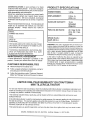
PRODUCT SPECBRCATRONS
HORSE
POWER:
1.6 hp
,HI
DISPLACEMENT:
(32.8 c,c)
, i LIII
GASOLINE
enable you to assemble and maintain your mini tilled
cultivator properly.
Always observe the "SAFETY
RULES."
CAPACITY:
FUEL/OIL
MIX RATIO:
ii
SPARK PLUG :
(GAP .035 in.)
THE MODEL AND DATE CODE WILL BE FOUND
ON A DECAL ON THE StDE OF THE MIN! TILLER!
CULTIVATOR TINE SHIELD
24:1 Gas To Oil
Gal.
,,HHH,H
Champion
CJ -8Y
WARNING: This unit is equipped with an internal combustion engine and should not be used on or near any
unimproved forest-covered, brush-covered or grass-covered land unless the engine's exhaust system is equipped
with a spark arrester meeting applicable local or state
faws (if any) tf a spark arrester is used, it should be
maintained in effective working order by the operator
YOU SHOULD RECORD BOTH DATE CODE AND
DATE OF PURCHASE AND KEEP tN A SAFE
PLACE FOR FUTURE REFERENCE
ill
AG REEMENT
In the state of California the above is required by law
(Section 4442 of the California Public Resources Code)
Other states may have similar laws Federal laws apply
on federal lands A spark arrester/muffler is available
through your nearest Sears Authorized Service Center
(See REPAIR PARTS section in this manual)
A Sears Maintenance Agreement is available on this
product. Contact your nearest Sears Store for details
CUSTOMER
Hill
16 oz.
Unleaded
(5 Oz. Oil/1
Gas)
DATE
CODE
DATE OF
PURCHASE
i ill
,,
(Regular)
MODEL
NUMBER 536..797500
,,,,i,lllllll
I
2.0 cu. in.
Please read and retain this manual. The instructions will
MAaNTENANCE
H""H'HH'"HH
RESPONSlBILEIES
Read and observe the safety rules
O
Follow a regular schedule in maintaining, caring for
and using your mini tiller/cultivator.
@ Follow the instructions under"Customer Responsibilities" and "Storage" sections ofthis owner's manual
LgMITED ONE-YEAR WARRANTY ON CRAFTSMAN
MiNi TILLER/CULTIVATOR
For one year from the date of purchase, when this Craftsman Mini tiller/cultivator is maintained, lubricated, and
tuned up according to the operating and maintenance instructions in the owner's manual, Sears will repair, free
of charge, any defect in material or workmanship
This warranty excludes tine(s), spark plug, and air cleaner which are expendable parts and become worn
during normal use
If this Mini tiller/cultivator is used for commercial or rental purposes, this warranty applies for only 30 days from
the date of purchase This warranty applies only while this product is in use the United States WARRANTY
SERVICE IS AVAILABLE BY RETURNING THE M1Nl TILLER!CULTWATOR TO THE NEAREST SEARS
SERVICE CENTER IN THE UNITED STATES
This warranty gives you specific legal rights, and you may also have other rights which vary from state to state
SEARS, ROEBUCK AND CO.,D817WA,
3
Hotfman Estates, IL 60179 USA
TA LE OF CONT
TS
SERVICE AND ADJUSTMENTS
...............16-17
STORAGE ..................................................................
t8
TROUBLE SHOOTING .................................... 19
REPAIR PARTS
(MINI TILLE R/CULTIVATOR)
................. 20-25
REPAIR PARTS (ENGINE) ....................... 26-29
PARTS ORDERING/SERVICE
......Back Cover
SAFETY RULES ................................................ 2
PRODUCT SPECIFICATIONS
...........................3
CUSTOMER
RESPONSIBILITIES
.... 3, 13-15
WARRANTY .............................................................3
TABLE OF CONTENTS
......................................4
CONTENTS OF SHIPPING CARTON ............5
ASSEMBLY ............................................................
6-8
OPERATION ................................................... 9-12
INDEX
F
A
Adjustments:
Carburetor .................................... 17
Assembly .......................................6-8
Tools Required ............................ 6
To Assemble ..............................6-8
Fuel:
Type .........................
Sto{age
......................
G
General Recommendations
11
17
....
13
C
Carburetor Adjustment ................ 17
Choke Control ..............................9,11
Check List:
Operation .................................. 8
Maintenance ............................. 13
Cleaning ..................................... 15
Controls, Mini tiller/cultivator .....9,t0
Cultivating Hints ......................... 12
Customer Responsibilities ,3,I3-15
General Recommendations .... 13
Lubrication ........................... 13,14
Mini tilledcultivator, ................. 13
Air Cleaner, Engine ................ 14
Cylinder Exhaust Ports ......... 14
Spark Plugs .............................14
E
Engine:
Air Cleaner ............................... 14
Gas arid Oil Mixture ............... 11
Preparation .......................... 10,11
Starting ........................................ t 1
Storage ...................................... 17
S
Safety Rules ......................
Service and Adjustments
Carburetor .......
2
t6-17
17
Specifications ............
Starting the Engine ..............
Stopping the Mini tiller/cultivator
Storage .....................
3
11
10
17
H
T
Hand Grip
Assembly .........................
L
Lubrication:
Mini tiller/cultivator
8
..............
Engine ........................
13
11
O
Operation ..........................
9-12
Operating
Your Mini tillerlcultivator
........... 10
Options
Spark Arrestor .........................
3
P
Parts Bag ....................................... 5
Product Specifications .............
3
R
Repair Parts:
Mini tiller/cultivator ...........
Engine ..............................
20-25
26-29
Table of Contents
Throttle Control
...........
4
Assembly ..............
Operation .....................
Tilling Hints ..................
Tines
8
9
12
Replacement
Troubleshooting
16
19
............
Points ...........
W
Warranty ..............
OONT
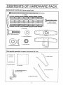
CONTENTS
[_
TS OF HA
OF PARTS
DWA
E PACK
BAG (shown actual size)
llllll|iilliililllill!,,!!!,!|lli!,!,,,,!,,,!,!,,!l!t!lllllllitlIllllll
1 - Tie Strap
/
I
I - 10-16 x 1_1t2 Inch
Washer
......
..................
Head Tap Screw
J
2 - Hand Grips
2 - Curved Head Screws
2 - 11/32 Inch Flatwashers
@
" L_'
!_ t-l-,I
't"
2 - 5/16-18 Hex Nuts
2 - Formed (Curved)
__J
Washers
2 - Tee Knobs
Parts packed
separately
in carton (not shown full size)
1I
I
I
I
I
1
I
I
i
i
(1) - Owner's
manual
(1) - Parts Rag
I
"
e"
(1) - Depth stake/transport
(1) -Right Lower Ha
els assembly
e
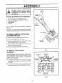
ASS
r
,,,,...........
,,, ,,,,,_
...............
i ,.,,,.i
................
CAUTION:
ALWAYS WEAR SAFETY
GLASSES OR EYE SHIELDS WHILE
ASSEMBLING
TILLER/ MINI TILLER/
CULTIVATOR.
IH HI
TOOLS REQUIRED
1 2 _
1 1 1-
I
RIGHT
_
i II,HI
FOR ASSEMBLY
5/16 inch Wrench (or adjustable wrench)
7/16 inch Wrenches (or adjustable wrenches)
Regular Screwdriver
Pair Scissors
Hammer
Figure 1 shows
assembled
LEFT
HANDLE
the mini tiller/cultivator
THROITLE
_
_
completely
Reference to the right and left hand side of the mini tiller/
cultivator is from the operator's position behind the unit
TO REMOVE MIN! TILLER/CULTIVATOR FROM CARTON
O
Remove the plastic parts bag from the carton
®
Remove the handles from the carton,
DEPTH _
__
@ Remove packing insert from carton that contains
depth stake/transport wheels assembly
@ Lift the tiller/mini tillerlcuitivator
out of the carton and
place on a hard level surface
®
Remove packing material from around tines
FIG. 1
TO INSTALL THE HANDLE
ASSEMBLY
The lower handles have a short bend at the bottom end
and are flattened at the top to allow the upper handle to
be placed between the lower handles To assemble the
handles, do the following:
•
®
Unwind the throttle control from around the engine
and straighten the cable. Be careful you do not kink
the cable.
4 WASHERS
2 LOCKNUTS
TINE
SHIELD
Nt.'_/_
COVER...
2HANDLE
_Z'_
=_-
I!i_il.___
n
Remove two {ocknuts, four washers and two handle
mounting screws from the tine shield (see Fig 2)
FRONT VI EW
ii NIHI
FIG,. 2
._.../
_
MOUNTING
, SCREWS
ASS
iii,iiiii
H I,
HI
0
@
O
@
Insert the right side lower handle section into the
mounting channel between the fine shield and the
engine casting (see Fig 3) Push the mounting
screws through the tine shield, handle and approximately half way into the engine casting Be sure a
washer is on each mounting screw (see Fig 4) It
may be necessary to rotate the lower handle to align
the mounting holes. To allow proper mounting of the
upper handle section be sure the flat portion of the
lower handle is facing inward
LY
'I
IIIII
I
Place the upper handie between the Iower handles
(see Fig 5) and secure with two curved head car_
riage bolts, two formed washers, two 11/32 inch
flatwashers and two tee knobs on the inside of the
handle. You must insert a hex nut into each tee
knob.. Finger tighten only. Pull back on the tee knob
to engage the hex opening with the hex nut Tighten
the tee knob. The nut will be pulled intothe cavity and
locked. The lower handles have two holes at the top
end to allow the upper handle to be positioned at two
different heights.
' H'H'HHHIHI
TINE
SHIELD
LOWER END
OF HANDLE
Position the left side lower handle section into the
mounting channel between the tine shield and the
engine casting Alig n the holes in the handle with the
engine casting and the tine shield, then push the
mounting screws completely through the engine
casting, handle and fine shield Install awasher onto
the mounting screws and secure the lower handle
sections using two Iocknuts previously removed (see
Fig. 4).. Finger tighten the focknuts at this time
MOUNTING
CHANNEL
FIG. 3
H,,,H,,,,,, HHH'H'
LOCKNUTS
WASHERS
WASH
Using two 7/16 inch wrenches, tighten the locknuts
on the screws in the lower ends ot the lower handles
just enough to hold the tower handles firmly in place
IMPORTANT:
O
'"HHHH' IHHI HH
OVERTIGHTENING THE SCREWS
ENOUGH TO CHANGE THE SHAPE
OF THE HANDLES CAN RESULT IN
DAMAGE TO THE ENGINE CASTING
Hold the curved head carriage bolt against the ouF
side of the lower handle while tightening the tee
knobs securely (see Fig 5)
T|NESHIELD
COVER
MOUNTING
SCREWS
FIG., 4
,
TO INSTALL THE TH ROTTLE
CONTROL ASSEMBLY
0
FORMED
WASHER
HAND GRIPS
Place a No 10 x 1-1/2 inch hex head screw down
through the hole in the upper handle right side and
attach the throttle control to the underside of the handle
11/32 INCH
FLATWASHER
TEE
KNOB
(see Fig 5)
0
0
Attach the throttle cable to the right lower handle by
threading a tie strap through the hole in the lower
handle and around the throttle cable on the outside of
the handle
NO. 10 X 1=1/2 INCH
HEX HEAD SCREW
HEX
NUT
Thread the pointed end of the strap through the other
(square) end of the strap and pull tight around the
throttle cable and lower handle.
LEFT
LOWER
NOTE: One side of the tie strap is rough, while the other
side is smooth The rough side must be on the inside of the
Ioopformedwhen the ends of thetie strap are put together
0
•
Try to loosen the tie strap, it it will loosen, it is put
together with the smooth side to the inside of the loop
Remove the tie strap and reverse the direction
THROTTLE
CONTROL
Out off excess strap
HAND GRIP ASSEMBLY
0
Install the hand grips onto the upper handles (see Fig
5). It may be necessary to lubricate the handles with
soap and water to aid assembly
,f
CHECKLIST
UPPER
HANDLE
CURVED HEAD
CARRtAGE BOLT
BEFORE YOU OPERATE AND ENJOY YOUR NEW
MINI TfLLER/CULT/VATOR, WE WISH TO ASSURE THAT
YOU RECEIVE THE BEST PERFORMANCE AND SATISFAC_
TfON FROM THIS QUALITY PRODUCT
RIGHT LOWEF
HANDLE
TIE STRAP
PLEASE REVIEW THE FOLLOWING CHECKLIST_
,/'
All assembly instructionshave been completed
4"
No remainingiooseparis in carton,
4"
All fasteners have been properly installed and tightened
WHILE LEARNING HOW TO USE YOUR MINI TtLLER/CULT/VATOR, PAY EXTRA ATTENTION TO THE FOLLOWING
IMPORTANT ITEMS:
,J',/ Fuel tank is filled with correct gasoline and oil mixture
v',f Become familiar with all controls-their location and
function Operate controls before starting engine
FIG. 5
OPERATnO
KNOW YOUR MRNI TILLER/CULTIVATOR
READ THIS OWNER'S
TILLER/CULTIVATOR,
MANUAL
AND SAFETY
RULES BEFORE
OPERATING
YOUR
MINI
Compare the illustrations with your mini tiller/cultivator to familiarize yourself with the
location of various controls and adjustments Save this manual for future reference
UPPER HANDLE
RECOIL STARTER HANDLE
SHUT-OFF
LEFT SIDE
LOWER HANDLE
THROTTLE
CONTROL
FUEL
TANK
AIR CLEANER
CHOKE CONTROL
RIGHT SIDE
LOWER HANDLE
TINE SHIELD
DEPTH STAKE/TRANSPORT
WHEELS ASSEMBLY
FIG. 6
SEARS MINI TILLER/CULTIVATOR conforms to the safety standards of the
American National Standards Institute B7t 8
THROTTLE CONTROL - Controls the engine speed and
the tine rotation, This mini tiller/cultivator is equipped with
a centrifugal clutch that engages the tine drive system
when the engine speed is increased
CHOKE CONTROL LEVER - Used to assist in starting a
cold engine,
SHUT-OFF SWITCH _ Used to stop the engine
RECOIL STARTER HANDLE - The engine on this mini
tiller/cultivator is equipped with an easy pu II recoil starter
DEPTH STAKE/TRANSPORT
WHEELS ASSEMBLYUsed (with wheels up) when tilling or cultivating to adjust
the depth of the cut It also acts as a brake to help the
operator control the direction and speed ol the unit
The depth stake/transpod wheel assembly (with wheels
down) can be used for transporting the unit
OPERATION
,,i ,i H,,mH,,
i,,i,,ii,,,
,NH
The operation of this mini titlertcultivator can result in foreign objects being thrown
into the eyes, which can result in severe eye damage Always wear' safety glasses
or eye shields while operating the mini tiller/cultivator.
We recommend standard safety glasses or Wide Vision Safety Mask for over your
glasses,
i ,,,m,i
m,m,,,l,,
i,, ii IN,,,
,N i,,,,,,,,,,,
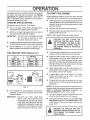
TO STOP MIN8 TILLERICULTIVATOR
CAUTION: GASOLINE IS FLAMMABLE
AND CAUTION MUST BE USED WHEN
HANDLING OR STORING IT. DO NOT
FILL FUEL TANK WHILE MINI TILLER/CU LTIVATOR IS RUNNING, HOT, OR WHEN MINI TILLER/
CULTIVATOR IS IN AN ENCLOSED AREA. KEEP
AWAY FROM OPEN FLAME, ELECTRICAL
SPARK, AND DO NOT SMOKE WHILE MIXING
FUEL OR FILLING THE FUEL TANK. NEVER
FILL FUEL TANK COMPLETELY; BUT FILL THE
TANK TO WITHIN t/4 - 1/2 INCH FROM THE TOP
TO PROVIDE SPACE FOR EXPANSION OF FUEL.
ALWAYS FILL FUEL TANK OUTDOORS AND
USE A FU NNEL OR SPOUT TO PREVENT SPILLING. MAKE SURE TO WIPE UP ANY SPILLED
FUEL BEFORE STARTING THE ENGINE.
@ Release the throttle control to stop the tines
@ Move the shut-off switch on the engine to the "OFF"
position
TO OPERATE
MIN! TILLER/CULTIVATOR
O
Set the depth stake/transport wheels assembly to the
desired tilling position as follows:
@
Remove the hairpin cotter from the clevis pin securing
"the depth stake (see Figure 8) Remove the clevis pin
and adjust the depth stake upward to dig shallower or
downward to dig deeper Reinstall the clevis pin and
hairpin cotter
@ Start the engine, tilt the unit back on the depth stake
until the tines are off the ground and squeeze the
throttle control all the way up against the hand grip
The engine is governor controlled and should be run
at full throttle
STORE GASOLINE IN A CLEAN, APPROVED
CONTAINER, AND KEEP THE CAP IN PLACE ON
THE CONTAINER. KEEP GASOLINE IN A COOL,
WELL VENTILATED PLACE; NEVER IN THE
HOUSE. NEVER BUY MORE THAN A 30 DAY
SUPPLY OF GASOLINE TO ASSURE VOLATILITY. GASOLINE IS INTENDED TO BE USED AS A
FUEL FOR INTERNAL COMBUSTION ENGINES;
THEREFORE, DO NOT USE GASOLINE FOR
ANY OTHER PURPOSE_ SINCE MANY CHILDREN LIKE THE SMELL OF GASOLINE, KEEP IT
OUT OF THEIR REACH BECAUSE THE FUMES
ARE DANGEROUS TO INHALE, AS WELL AS
BEING EXPLOSIVE.,
@ Graspthe handles firmly and slowiytiltthe unit forward
to begin the tilling action
@
As the tines begin to make contact with the ground,
hold back on the handles so that the tines will dig and
not ride forward over the ground Hold back until the
tines dig into the soil.
@
If the tilled depth is too deep ortoo shallow, turn off the
engine and reset the depth stake
@ If depthstake is not controlling forward action, lower
the depth stake If the unit is not going forward, raise
the depth stake
i
I_
!
BEFORE STARTING
ENGINE
FILL GAS
,i .................................
The two cycle engine used on this mini tilter/cultivator
requires a mixture of gasoline and oil for lubrication of the
bearings and other moving parts The correct fuel mixture
ratio is 24:1 (see Fuel Mixtu_e Chart) Gasoline and oil
must be premixed in a clean gasoline container Always
use fresh, clean unleaded gasoline
TATING TINES, ROTATING TINES CAN
CAUTION:
KEEP AWAY FROM THE RO"
CAUSE INJURY.
WARNING: Experience indicates thai alcohol blended
fuels (called gasahol or using ethanol or methanol) can
attract moisture which leads to separation and formation
of acids during storage Acidic gas can damage the fuel
system of an engine while in storage To avoid engine
problems, the fuel system should be emptied before
storage for 30 days or longer. Drain the gas tank, start
10
OPERATION
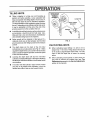
TO START THE ENGINE
the engine and tet it run until the fuel lines and carburetor
are empty Use fresh fuel next season See Storage
Instructions
for additional information, Never use en-
Before starting the engine, be sure you have read and
understood all the instructions on the preceding pages
gine or carburetor cleaner products in the fuel tank or
permanent damage may occur
GASOLINE
@ Fill the fuel tank (to 1/2 inch below the bottom of the fill
neck) with fresh fuel mix and reinstall the fuel tank cap
securely Never use fuel that may be stale from long
periods of storage
AND OIL MIXTURE
Mix gasoline and oil (See Fig 7) as follows:
@ Pour 1 US quart of fresh, clean, unleaded automotive gasoline into a gallon gasoline container,
@ Move the shut-off switch to the ON position
@ Movethechokecontrol(see
Fig 6) tothe FULLchoke
position (all the way down)
@ Add (5 oz ) of clean, high quality SAE 30 or SAE 40
two-cycle oil into the gasoline container
IMPORTANT:
NOTE: A warm engine should not require choking
DO NOT USE OUTBOARD MOTOR
OIL OR MULTI-VISCOSITY
OILS,
SUCH AS t0W-30 OR 10W-40,
JuJJlu_L
THROTTLE CONTROL WHILE STARTCAUTION:
DO NOT
THE
ING THE ENGINE.
THE TOUCH
MINI TILLER/
CULTIVATOR WILL PROPEL ITSELF IF
THE ENGINE SPEED IS ADVANCED
FROM IDLE,
@ Reinstall the cap on the gasoltne container and shake
container vigorously so the oil mixes with the gasoline
@ Add an additional 3 U S quarts of gasoline to the
gallon container and shake the container again
FUEL MIXTURE
CHART
24:1)
S. I. (METRIC)
U°S,
GAS
(Mixture
OIL
GAS
O
Tilt the mini tiller/cultivator back on the depth stake or
transport wheels to raise the tines off the ground
O
Grasp the upper handle firmty to stabilize the mini
tiller/cultivator and pull the starter handle with short
quick pulls Do not allow the starter handle to snap
back, let it rewind slowly while holding the starter rope
It will take a few pulls on the starter handle to leed gas
from the fuel tank to the carburetor
O
When engine starts, move the choke control to 1/2
choke position until the engine runs smoothly Then
move choke controI to OFF position
O
If engine lalters, move choke control to 1/2 choke
position until engine runs smoothly
Then move
choke control to OFF position
O
If engine fires, but does not continue to run, move
choke control to no choke position and repeat starting
instructions
OIL
ii ,lllllll
1 Gal.
2 Gal.
5 Gal,
5 oz,
11 oz.
27 oz.
4 Liters
8 Liters
20 Liters
.167 L
.333 L
,833 L
oP.,
1_."m
cup _ s _z.)
+
1 _Le.,cxL_ote
"_
NOTE: If the tines do not stop when the throttle control is
released, adjust the carburetor idle speed as instructed in
Step 5 of Carburetor Adjustment
paragraph in the
Service/Adjustments
section of this manual
FIG. 7
O
This completes the special gasoline mixing (24:1)
procedure. It can now be poured into the mini tiller/
cultivator fuel tank
IMPORTANT:
DO NOT FILL FUEL TANK WITH
GASO- LINE THAT DOES NOT HAVE
OIL MIXED IN IT DO NOT USE GASOLINE ADDITIVES BECAUSE THE ENGINE MAY BE DAMAGED SHAKE THE
GASOLINE
CONTAINER
BEFORE
EACH FILLING OF THE FUEL TANK
•
To stop the engine, release the throttle control and
move the shuFoff switch to the OFF position
O
If the engine becomes flooded, see the Spark Plug
Maintenance paragraph in the Maintenance section
of this manual Then pull the starter rope with the
choke "OFF"
CAUTION: THE MUFFLER AND SURROUNDING AREAS BECOME HOT AFTER RUNNING THE ENGINE, AVOID
THESE AREAS,,
11
ii
lull
ullll,l,i
TILLING HINTS
O
DEPTHSTAKE/
TRANSPORT
WHEELS'
Tilling is digging in, turning over and breaking up
packed soil before planting, Loose unpacked soil
helps rootgrowth, Best tilling depth is 4 to 6 inches, A
tiller will also clear the soi! of unwanted vegetation
The decomposition of this vegetation matter enriches
the soil, Depending on the climate (rainfall and wind),
it may be advisable to till the soil at the end of the
growing season to further condition the soil,,
O
Avoid tilling the soil that is too dry as the soil pulverizes
and produces a dust that will not hold water, Also,
tilling soil that is too wet will produce unsatisfactory
clods besides being hard on the machine,
O
Better growth will be obtained in tilled ground if a
relatively small area is tilled properly and the tilled
ground used soon after tilling to preserve the moisture
content,
®
The depth stake (on the back of the mini tilleff
cultivator)sewes a dual purpose (see Fig 8) It helps
regulate the depth of the cut to a uniform level and also
acts as a brake to help the operator control the speed
of the mini tiller/cultivator,
®
Lowering the depth stake will slow the mini tiller/
cultivator and make it till deeper Raising the depth bar
will allow the mini tiller/cultivator to move faster and till
more shallow_
®
If the tiller' mini tiller/cultivator stops forward motion
and tries to dig deeper than necessary, move the
handles from side to side to start forward motion
CLEVIS PIN
)EPTH STAKE
BRACKET
HAIRF
FIG_ 8
CULTIVATING
12
HINTS
O
When cultivating (weed killing) it is best to till no
deeper than 1-1/2 inches Tilling deeper will only pull
to the surface ungerminated weed seeds You may
want to raise the depth bar to lessen the braking
action
O
When cultivating around plants or close areas you
may want to remove the outside tines (see Tine
Replacement paragraph in the Service/Adjustments
section of this manual),
ESPONSI
ILITIES
, ,,,,,,,,,,,, ,,,
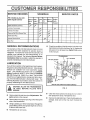
SCHEDULE
Fill in dates as you complete regular service
i,,inu
m i==
SERVICE
xz
DATES
,x
Before After Every Every Before Before
Each first 2 25
75
Storage Each
Season
Use
Hours Hours Hours
=
i
.
Tighten All Screws and Nuts
Lubricate Transmission
v"
Lubricale Tine Shaft
Clean and Re-Oii Air Cleaner Fifter
11
Check Spark Plug
11
Cyfinder Exhaust Ports
Drain Fuel
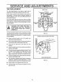
GENERAL
v"
RECOMMENDATIONS
O
Check the condition of the felt washer in the side of l he
transmission at lhe line shaft (see Fig 9) Replace the
felt washer if it is damaged (see Repair Parts section
in this manual)
The warranty on this mini tiller/cultivator does not cover
items that have been subjected to operator abuse or
negligence To receive full value from the warranty, the
operator must maintain the mini tiller/cultivator as instructed in this manual. The following Service Recommendations Chart is provided to assist the operator in
properly maintaining the mini tiller/cultivator
TRANSMISSION
FELT WASHER
AIR VENT SCREW
LUBRiCATiON
Every 25 hours and/or at the beginning of each season,
the gear box should be filled with lubricant, Tubesofgear
lubricant are available from most automotive supply
stores Use portable tool grease such as Lubriplate
630AA (Product No 06787-1-3/4 oz tube) or Lubriplate
GR-132 (Product No 15892-10 oz tube), The tine shaft
should have oil applied before storage and after cleaning, if the mini tiller/cultivator is flushed with water The
following illustration is provided to assist the operator in
properly maintaining the mini tiller/cultivator
TINE SHAFT
line
before
storage and
after
cleaning, if
the mini titler/
cultivator ts
flushed with
iter)
GREASE
FITTING
(Lubricate the
gear box with
lubdplate
630AA or
Lubrlplate
GR-132
VIEW OF LEFT SIDE WITH TINES REMOVED
i,,u
FIG,. 9
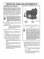
TO
COOL ALLOW
BEFORE
WITH
CAUTION:
THE FILLING
TRANSMISSION
GREASE,
@ Remove both left side tines (see Adjustments/
pairs section) in this manual..
O
Clean line shaft, spread a few drops of oil on shalt in
tine replacement areas Reinstall the tines
O
Remove the right side tines Checkthefeltwasherfor
damage, clean and oil the tine shaft Reinstall the
tines.
Re-
O
Remove the air vent screw (see Fig 9) fromthe top left
side of the transmission.
O
Using a grease gun, fill the transmission through the
grease fitting until the new grease begins to come out
of the air vent screw hole
O
Reinstallthe air vent screw.
,mH
13
,= = ,===IH=
CUSTO
ENGINE
FOAM ELEMENT
AIR CLEANER
MAINTENANCE
SCREW
The air cleaner filter should be cleaned and reoiled after
every 25 hours of use Clean more often under dusty
conditions
IMPORTANT:
THE ENGINE CAN BE WORN OUT IN
A VERY SHORT PERIOD OF TIME IF
DtRT OR GRIT IS ALLOWED TO ENTER THE ENGINE.
To clean the air filter, do the following:
O
Loosen screws on air cleaner cover (see Fig 10) and
remove the cover..
COVER
HOUSING
@ Remove foam element from air cleaner
®
Wipe inside of the air cleaner housing clean
•
Clean the foam element by washing in a strong
solution of water and household detergent. Then
rinse thoroughly in clean water.
®
FIG., 10
SPARK
tf the engine is flooded, clean the area around the spark
plug base to prevent foreign material from entering the
cylinders when the plug is removed Remove and dry the
spark plug. Regap the electrodes to 035 it necessary If
a new spark plug is needed, refer to the Engine Operation and Maintenance manual for the proper replacement spark plug. Tighten the spark plug firmly If a torque
wrench is available, torque the spark plug to 15 tootpounds
Wrap foam element in clean cloth and squeeze out
(do not twist) all the liquid until dry.
@ Cover the ends and side of the foam element with
same oil used in fuel mixture
Knead the foam
element between fingers to distribute oil and remove
excess oil
®
Reinstall foam element in air cleaner housing.
®
Service the foam element carefully, inspection for
deterioration or damage
A defective, improperly
serviced, or misassembled air filter will allow dirt
particles to enter the engine_
@
PLUG MAINTENANCE
CYLINDER
EXHAUST
PORTS
The cylinder exhaust ports should be cleaned after each
seventy-five (75) to one hundred (100) hours of operation For this procedure we recommend that you take
your unit to a technician trained to work on two cycle
engines, such as a SEARS Service Center
Reassemble the filter (see Fig 10) Place the cover
on the air cleaner housing and tighten screws to
secure cover to the housing_
CAUTION: NEVER RUN THE ENGINE
WlTHOUTTHE AIR CLEANER ELEMENT
INSTALLED.
A DEFECTIVE
AIR
CLEANER CAN RESULT IN LOSS OF
ENGINE POWER AND CAN CAUSE EXCESSIVE WEAR OR DAMAGE TO THE
ENGINE COMPONENTS
IF DIRT OR
DUST IS PERMITTED TO ENTER THE
ENGINE THROUGH THE CAR BURETOR,
AN AIR CLEANER THAT IS CLOGGED
WITH DUST OR DIRT SHOULD BE
CLEANED AND RE-OILED.
t4
C STO
E
ESPO
,,,Hnl,,u
i
,,, ,,,,,,,,,,,,,,,,,,u,u,,,,unl,iHuu,
ES
u,i
CLEANING
Always remove the dirt and debris from the mini tiller/
cultivator after each use (see Fig_ 11), Remove any
string, wire or vegetation thai may become lodged in the
mechanism and stop the tine rotation Proceed as follows:
@ Release the throttle control and move the shut-off
switch to the OFF position, then disconnect the spark
plug wire.
@
Remove the hairpin and clevis pin securing the tine(s)
assembly to the shaft and remove the tine(s) (see Fig
11)..
e
Remove the lodged material. Reassemble the tine(s)
on the shaft and secure with a clevis pin and hairpin
O
Reconnect the spark plug wire and restart the engine
FRONT VIEW
TINE SHIELD
LODGED ITEM
CLEVIS
CLEVIS PINS
PINS
LEFT SIDE
TINES
RIGHT SIDE
TINES
HAIRPINS
TRANSMISSION
FIG.. 11
15
HAIRPINS
SERVICE AN
T$
TINE REPLACEMENT
The mini tiller/cultivator is left hand or right hand as
viewed from the operator's position behind the unit
All four tines on this unit are different and cannot be
interchanged. The tines must be properly installed as
shown in figures 12 and 13 or the mini tillerlcultivator will
not function properly
The outside tines may be removed to reduce the tilling
width to about 7 inches, for working close around plants
orin small areas, if desired_ When reinstalling the outside
tines see below.
LEFT SIDE
TINES
RIGHT'SIDE
TINES
HAIRPINS
The tines will all wear fairly evenly_ If the tines are being
replaced because of wear, we recommend that all four
tines be replaced at the same time To replace the tines,
do the following:
O
Place the shut-off switch to the OFF position and
disconnect the spark plug wire
O
Removethe hairpins andthe clevis pinsfromthe tines
on one side of the uriit and remove the tines
O
Clean the fine shaft and oil the shaft at the tine
locations.
O
Place the inside tine on the tines haft and reinstall the
FIG. 12
PROPERLY
INSTALLED
RIGHT SIDE TINES
clevis pin and hairpin.
O
When the tines are properly installed, the letter"R" will
be visible on the outside of the righFhand tine (the
letter "L" on the left-hand tine). The letter should
appear opposite the smait hole in the side of the tine
O
Piacethe outsidetineonthe tine shaft and reinstallthe
clevis pin and hairpin cotter.
®
The outside tine cutting tips will all bend in toward the
inside tine The letter "R" or] t he right side or"L" on the
left side should be visible from the outside of the unit.
•
Repeat steps on the opposite side of the unit.
O
Check to make sure the tines are installed on correct
side of the unit
RIGHT SIDE INDICATOR
FIG,, 13
16
SERVICE AND ADJUST
JlUlUU,,,i,ii iu,,
CARBURETOR
L,
,,
i
i ,
E TS
i i
.....................................
ADJUSTMENT
A dirty air cleaner will cause the engine to run
improperly and/or smoke excessively, Be sure the
air cleaner is clean before adjusting the carburetor,
Never make unnecessary adjustments to the carburetor
The carburetor was set at the factory to operate efficiently
under most applications However, if adjustments are
required, we recommend you contact you r nearest SEARS
Service Center If you feel that you are competent to
make carburetor adjustment proceed as follows:
CAUTION: USE EXTREME CARE WHEN
MAKING ADJUSTMENTS
THAT REQUIRE THE ENGINE TO BE RUNNING,
KEEP HANDS, FEET, HAIR AND LOOSE
CLOTHING AWAY FROM ANY MOVING
PART,
@ Turn the mixture adjustment screw (see Fig
clockwise to close
IMPORTANT:
\
IDLE SPEED
ADJUSTING
SCREW
CARBURETOR
14)
ENGINE SHOWN WITH AIR CLEANER
TIGHTEN THE ADJUSTING SCREW
WITH YOUR FINGERS TO PREVENT
DAMAGE TO THE CARBURETOR OR
ADJUSTING SCREW.
O
Start the engine and let itwarm up approximately 3 to
5 minutes Do not adjust the carburetor when the
engine is cold
e
It the engine falters or stops after the choke lever is
moved to the OFF position, open the mixtu re adjusting
screw an additional 1/8 turn counterclockwise
e
With the engine running, release the throttle control
(idle position) to make the mixture adjustments
a.
Turn the mixture adjusting screw (see Fig 14)
slowly clockwise until the engine falters Notethis
location.
b
Turn the mixture adjusting screw slowly counterclockwise until the engine starts to sputter Note
this bcation
REMOVED
FIG, 14
@ Turn the mixture screw counterclockwise (open) one
(1) turn,
CAUTION: NEVER TAMPER WITH THE
ENGINE GOVERNOR WHICH IS FACTORY SET FOR PROPER
ENGINE
SPEED° OVER-SPEEDING THE ENGINE
ABOVE THE FACTORY HIGH SPEED
SETTING CAN BE DANGEROUS° IF YOU
THINK THE ENGINE GOVERNED HIGH
SPEEDS NEEDS ADJUSTING, CONTACT
YOUR NEAREST SEARS SERVICE CENTER WHICH HAS THE PROPER EQUtP_
MENTAND EXPERIENCETO MAKE ANY
NECESSARY ADJUSTMENTS..
O
C_
MIXTURE
ADJUSTING
SCREW
Turn the mixture adjusting screw clockwise until
it is hallway between the first position where the
engine faltered and the second position where
the engine started to sputter
The idle speed may need to be adjusted alter making
the mixture adjustment If the tines do not turn when
the engine is running and the throttle control is reIeased, the idle speed witl not need adjusting If the
tines turn when the throttle control is released, do the
following:
a
Have someone holdthe minitiller/cu!livator
on
17
back
the depth bar withthetines off the ground
b
Startthe engine
c
With the throttle in the released (idle) position,
turn the idle speed adjusting screw counterclockwise until the tines stop rotating
IH=I=,l=l ,=l,=l ,=l,ll
STORAGE
= = i
i
= H=,l
,m,,,mm,,,
H ,,
11, i
ENGINE
CAUTION:
NEVER STORE ENGINE
WITH FUEL IN TANK INDOORS OR IN
IMPORTANT:
ENCLOSED, POORLY VENTILATED
AREA, WHERE FUEL FUMES MAY
REACH AN OPEN FLAME, SPARK OR
PILOT LIGHT AS ON A FURNACE, WA*
TER HEATER, CLOTHES DRYER, ETC_
NOTE: The tlledmini tiller/cultivator should be immediately prepared for storage at the end of the season or if
the unit
will not be used for' 30 days or more
MiNi TILLER/CULTIVATOR
O
Thoroughly clean the mini tiller/cultivator Remove all
dirt and debds from the engine and unit
•
Removethetinesandoilthetineshaftand
reinstallthe
'tines (see ServicefAdjustments
section in this
manual)
@ Drain the luel from the fuel tank into an approved
container outdoors, away from open flame
@ Start and run the engine until it stops due to lack of fuel
@ Loosen the tee knobs that secure the upper handle to
the lower handle,
e
@ Carefully fold the upper handle down making sure the
throttle is not kinked Tighten the tee knobs
@
•
IT IS IMPORTANT TO PREVENT GUM
DEPOSITS FROM FORMING tN ESSENTIAL
FUEL SYSTEM
PARTS
SUCH AS THE CARBURETOR, FUEL
FILTER, FUEL HOSEORTANK
DURINGSTORAGE
ALSO, EXPERIENCE
INDICATES
THAT
ALCOHOL
BLENDED FUELS (CALLED GASOHOLOR USING ETHANOLOR METHANOL) CAN ATTRACT
MOISTURE
WHICH LEADS TO
SEPARATION
AND FORMATION OF ACIDS DURING STORAGE
ACIDIC GAS CAN
DAMAGE THE FUEL SYSTEM OF AN
ENGINE WHILE IN STORAGE
Pull the starter handle slowly until you feel resistance
due to compression pressure, then stop
The cross piece of the upper handle (between the
lower handles) can now be used as a carry handle or
can be hooked over a wail hook to store the mini tilled
Release the starter tension slowly to prevent the
engine from reversing due to compression pressure
This position wilt close both the intake and exhaust
ports to prevent corrosion of the piston and cylinder
bore
OTHER
cultivator up off the floor out of the way
NOTE: A yearly checkup or tuneup by a SEARS Service
Center is a good way to insure that your mini tiller/
cultivator will provide maximum performance for the next
season
@ If possible, store your mini tilter/cultivatorindoors and
cover it to give protection from dust and dirt
@ Cover the mini tiller/cultivator with a suitable protective cover that does not retain moisture Do not use
plastic
IMPORTANT:
18
NEVER COVER THE
MINI TILLER/
CULTIVATOR WHILE THE ENGINE
AND EXHAUST AREAS ARE STILL
WARM
CAUSE
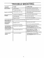
"TROUBLE
J,
CORRECTION
H =,,=l
H,L
H .1
H ,,,
, , ==lill
=
i
, L
=l
.H HN,=_I
H
=l =l
HH,,,
=
............,,,.....
I I HI=
= ..
I
Check fuel mix chart and mix fresh fuel
N i....
,=
==l
H.,=
i,H.
IHNHH.l=
H l=,. HHHI
'1
Clean fuel tank, Fuel tank should be half full
Dirt in fuel tank or out of fuel
Engine runs erratically
HN=I
,=
Too much oil in mixture
1111
=
Drain fuel tank Fill with fresh mixture
Stale fuel mixture
Difficult starting
when starting engine
i ii
Engine will not run at
full speed
=lq
See carburetor adjustment section
Carburetor out of adjustment
Clean and re-gap plug
Fouled spark plug
................
H Hi
H,,
!,,
................... ,1
,/
H
HI
Debris interferring with throttle linkage
Engine speed does not
increase properly
ii
Engine smokes
excessively
illlllll=
=ll,l,,,i,l_
i
HliHl=
H.,Jl
, ...................
Clean and re-oil air cleaner
Plugged air cleaner
ii i..
=
HHi"LH.
Blow did and debris off top of carburetor
=l
Plugged air cleaner
Clean and re-oil air cleaner
Too much oil in fuel mixture
Check fuel mix chart and mix fresh fuel
Carburetor out of adjustment
Adjust carburetor idle speed See
Carburetor Adjustment paragraph in
Service/Adjustments
section of this manual
=
Tines continue to
rotate when throttle the
control is released
=1
=
Tines will not turn
HI
i= ii=
H
H,,,....................
==
ii.
H,IH=
l=,,,=
Remove lodged item See Keep
Tiller/Cutlivator
Clean paragraph in the
Operation section of this manual
Foreign object lodged in tine
L
Unit does not till
, =l=
i ii.,i.
•
liH.....,J
===l,=
= 1.
1, i
1,
.HHHH,
Check the tines for proper installation See the
Tine Replacement paragraph in the
ServicetAdjustment
section of this manual
Incorrect fine installation
properly
19
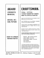
OWNER'S
AL
MODEL NO.
536.797500
32o8CC 2oCYCLE
10 INCH DIAMETER TUNERS
MiNi TNLLER/CULT_VATOR
Each CULTIVATOR
has its own MODEL
BER found on the tine shieldv
Each ENGINE has its own MODEL
found on the BLOWER HOUSING.
NUM-
NUMBER
Always mention these MODEL NUMBERS when
requesting
service or Repair Parts for your
CULTIVATOR,
All parts may be ordered through any Sears,
Roebuck and Company
Service Centers and
most Retail Storesv
WHEN ORDERING
REPAIR
PARTS,
GIVE THE FOLLOWING INFORMATION:
HOW TO ORDER
REPAIR PARTS
* PRODUCT-
ALWAYS
MINI TILLER/CULTIVATOR
* MODEL NUMBER - 53&797500
* ENGINE MODEL NUMBER - 143o941600
* PART NUMBER
* PART DESCRIPTION
"You[ Sears me[chandise has added value when you
consider that Sears has service units nationwide staffed
with Sears trained technicians,. Prolessional technicians
specifically trained on Sears Products, having the parts,
tools and equipment to insure that we meet our pledge
to you, we service what we sell."
SEARS, ROEBUCK AND CO., Hoffman Estates, IL 60179 USA
331518
12/01193
Printed
in UoSoA.