1
i
OWNER'S
MANUA
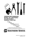
MODEL NO. SPGT2254
22.0 HP 54 INCH
GARDEN TRACTOR
•
Assembly
°
Operation
°
Maintenance
°
Service
°
and
Adjustments
Storage
•
Troubleshooting
•
Espa_ol
For Parts and Service, contact our authorized distributor:
call 1-800-849-1297
ForTechnical Assistance: call 1-800-829-5886
SOUTHERN
STATES
195482
Rev. 2 3.22.05 RD
PRINTED IN U.S.A.
Warranty ................................................
Safety Rules ..........................................
Product Specifications
...........................
Assembly/Pre-Operation
.......................
Operation .............................................
2
3
6
8
12
Maintenance
.......................................
Maintenance
Schedule ........................
Service and Adjustments
.....................
Storage ................................................
Troubleshooting
...................................
EspaSol ................................................
19
19
23
29
30
34
LIMITED WARRANTY
The Manufacturer
warrants to the original consumer purchaser
that this product as
manufactured
is free from defects in materials and workmanship.
For a period of two
(2) years from date of purchase by the original consumer purchaser,
we will repair or
replace, at our option, without charge for parts or labor incurred in replacing parts, any
part which we find to be defective due to materials or workmanship.
This Warranty is
subject to the following limitations
and exclusions.
1. This warranty does not apply to the engine, other than EHP manufactured
transaxle/
transmission
components,
battery (except as noted below) or components
parts
thereof. Please refer to the applicable manufacturer's
warranty on these items.
2. Transportation
charges for the movement
of any power equipment
unit or attachment
are the responsibility
of the purchaser.
Transportation
charges for any parts submitted for replacement
under this warranty must be paid by the purchaser unless such
return is requested
by Electrolux Home Products.
3. Battery Warranty:
On products equipped with a Battery, we will replace, without
charge to you, any battery which we find to be defective in manufacture,
during the
first ninety (90) days of ownership. After ninety (90) days, we will exchange the Battery, charging you 1/12 of the price of a new Battery for each full month from the date
of the original sale. Battery must be maintained
in accordance
with the instructions
furnished.
4.
The Warranty period for any products used for rental or commercial
purposes is
limited to 90 days from the date of original purchase.
5. This Warranty applies only to products which have been properly assembled,
adjusted, operated, and maintained
in accordance
with the instructions
furnished. This
Warranty does not apply to any product which has been subjected to alteration,
misuse, abuse, improper assembly or installation,
delivery damage, or to normal wear of
the product.
6. Exclusions:
Excluded from this Warranty are belts, blades, blade adapters, normal
wear, normal adjustments,
standard hardware and normal maintenance.
7. In the event you have a claim under this Warranty, you must return the product to an
authorized
service dealer.
Should you have any unanswered
questions concerning
this Warranty, please contact:
Electrolux Home Products, Inc.
In Canada contact:
Outdoor Products Customer Service Dept.
Electrolux Canada Corp.
250 Bobby Jones Expressway
7075 Ordan Drive
Augusta, GA 30909 USA
Mississauga, Ontario
L5T 1K6
giving the model number, serial number and date of purchase of your product and the
name and address of the authorized
dealer from whom it was purchased.
THIS WARRANTY
DOES NOT APPLY TO INCIDENTAL
OR CONSEQUENTIAL
DAMAGES
AND ANY IMPLIED WARRANTIES
ARE LIMITED TO THE SAME TIME
PERIODS
STATED HEREIN FOR OUR EXPRESSED
WARRANTIES.
Some areas do
not allow the limitation of consequential
damages or limitations
of how long an implied
Warranty may last, so the above limitations
or exclusions
may not apply to you. This
Warranty gives you specific legal rights, and you may have other rights which vary from
locale to locale.
This is a limited Warranty within the meaning of that term as defined in the MagnusonMoss Act of 1975.
IMPORTANT:This cutting machineis capableof amputatinghands and feet and throwing objects.Failureto observe the followingsafety instructionscould result in serious
injury or death.
•
WARNING: In orderto prevent
accidentalstarting when setting up,
transporting,adjustingor making repairs,
always disconnectspark plug wire and
placewire where it cannotcontact spark
plug.
WARNING: Do not coast down a
hill in neutral,you may losecontrol of the
tractor.
•
•
WARNING: Tow only the attachmentsthat are recommendedby and
complywith specificationsof the manufacturerof your tractor.Use common
sense when towing.Operateonly at the
lowestpossiblespeed when on a slope.
Too heaw of a load, while on a slope,is
dangerous. Tires can lose traction with
the ground and causeyou to lose control
of your tractor.
WARNING: Engine exhaust, some
•
•
•
of its constituents,
and certain vehicle
components
contain or emit chemicals
known to the State of California to cause
•
cancer
ductive
•
and birth defects
harm.
WARNING:
Battery
and related accessories
or other reproposts, terminals
contain lead and
lead compounds,
chemicals
State of California to cause
•
•
known to the
cancer and
birth defects or other reproductive
Wash hands after handling.
•
harm.
•
I. GENERAL
•
•
•
•
•
•
OPERATION
Read, understand,
and follow all
instructions
on the machine and in the
manual before starting.
Do not put hands or feet near rotating
parts or under the machine. Keep clear
of the discharge
opening at all times.
Only allow responsible
adults, who are
familiar with the instructions,
to operate
the machine.
•
•
Clear the area of objects such as
rocks, toys, wire, etc., which could be
picked up and thrown by the blades.
Be sure the area is clear of bystanders before operating.
Stop machine if
anyone enters the area.
Never carry passengers.
Do not mow in reverse
unless abso-
lutely necessary.
Always look down
and behind before and while backing.
Never direct discharged
material
toward anyone. Avoid discharging
material against a wall or obstruction.
Material may ricochet back toward the
operator. Stop the blades when crossing gravel surfaces.
Do not operate machine without the
entire grass catcher, discharge guard,
or other safety devices in place and
working.
Slow down before turning.
Never leave a running machine
unattended.
Always turn off blades,
set parking brake, stop engine, and
remove keys before dismounting.
Disengage
blades when not mowing.
Shut off engine and wait for all parts to
come to a complete stop before cleaning the machine, removing the grass
catcher, or unclogging the discharge
guard.
Operate machine only in daylight or
good artificial light.
Do not operate the machine while
under the influence of alcohol or drugs.
Watch for traffic when operating near
or crossing roadways.
Use extra care when loading or unloading the machine into a trailer or truck.
Always wear eye protection when operating machine.
Data indicates that operators, age 60
years and above, are involved in a
large percentage
of riding mower-related injuries. These operators should
evaluate their ability to operate the
riding mower safely enough to protect
themselves
and others from serious
injury.
Follow the manufacturer's
recommen-
dation for wheel weights or counterweights.
Keep machine free of grass, leaves or
other debris build-up which can touch
hot exhaust / engine parts and burn.
Do not allow the mower deck to plow
leaves or other debris which can cause
build-up to occur. Clean any oil or fuel
spillage before operating or storing the
machine. Allow machine to cool before
3
storage.
II. SLOPE
OPERATION
Slopes are a major factor related to loss of
control and tip-over accidents, which can
result in severe injury or death. Operation on all slopes requires extra caution.
If
you cannot back up the slope or if you feel
uneasy on it, do not mow it.
•
Mow up and down slopes, not across.
•
Watch for holes, ruts, bumps, rocks, or
other hidden objects.
Uneven terrain
could overturn the machine.
Tall grass
can hide obstacles.
•
•
Choose a low ground speed so that
you will not have to stop or shift while
on the slope.
Do not mow on wet grass. Tires may
lose traction.
Always keep the machine in gear when
going down slopes. Do not shift to
neutral and coast downhill.
•
•
•
•
•
Avoid starting, stopping, or turning on
a slope. If the tires lose traction,
disengage the blades and proceed slowly
straight down the slope.
Keep all movement
on the slopes slow
and gradual.
Do not make sudden
changes in speed or direction, which
could cause the machine to roll over.
Use extra care while operating machine with grass catchers or other attachments;
they can affect the stability
of the machine. Do no use on steep
slopes.
Do not try to stabilize the machine by
putting your foot on the ground.
Do not mow near drop-offs, ditches,
or embankments.
The machine could
suddenly roll over if a wheel is over the
edge or if the edge caves in.
III. CHILDREN
Tragic accidents
can occur if the operator
is not alert to the presence
of children.
Children are often attracted to the machine
and the mowing
activity.
Never assume
that children
will remain where you last
saw them.
•
Keep children out of the mowing area
and in the watchful care of a responsible adult other than the operator.
•
Be alert and turn machine off if a child
enters the area.
•
Before and while backing, look behind
and down for small children.
•
•
•
Never carry children, even with the
blades shut off. They may fall off and
be seriously injured or interfere with
safe machine operation. Children who
have been given rides in the past may
suddenly appear in the mowing area
for another ride and be run over or
backed over by the machine.
Never allow children to operate
machine.
the
Use extra care when approaching
blind
corners, shrubs, trees, or other objects
that may block your view of a child.
IV. TOWING
•
•
Tow only with a machine that has a
hitch designed for towing. Do not attach towed equipment
except at the
hitch point.
Follow the manufacturer's
recommen-
•
dation for weight limits for towed equipment and towing on slopes.
Never allow children or others in or on
•
•
towed equipment.
On slopes, the weight of the towed
equipment
may cause loss of traction
and loss of control.
Travel slowly
to stop.
and allow extra distance
V. SERVICE
SAFE
HANDLING
OF GASOLINE
To avoid personal injury or property
damage, use extreme care in handling
gasoline. Gasoline is extremely
flammable
and the vapors are explosive.
•
Extinguish all cigarettes,
cigars, pipes,
and other sources of ignition.
•
Use only approved gasoline container.
•
Never remove gas cap or add fuel with
the engine running. Allow engine to
cool before refueling.
•
Never fuel the machine indoors.
•
Never store the machine or fuel con-
•
tainer where there is an open flame,
spark, or pilot light such as on a water
heater or other appliances.
Never fill containers
inside a vehicle
or on a truck or trailer bed with plastic
liner. Always place containers
on the
ground away from your vehicle when
filling.
•
•
•
•
Removegas-poweredequipmentfrom
the truck or trailer and refuel it on the
ground. If this is not possible,then
refuelsuch equipment with a portable
container, rather than from a gasoline
dispenser
nozzle.
Keep the nozzle in contact with the rim
of the fuel tank or container
opening at
all times until fueling is complete.
Do
not use a nozzle lock-open device.
If fuel is spilled on clothing, change
clothing immediately.
Never overfill fuel tank. Replace gas
cap and tighten securely.
GENERAL
•
•
•
•
•
•
•
•
•
•
•
•
•
SERVICE
•
Never operate machine in a closed
area.
Keep all nuts and bolts tight to be sure
the equipment
is in safe working condition.
Never tamper with safety devices.
•
•
Be sure the area is clear of bystanders before operating.
Stop machine if
anyone enters the area.
Never carry passengers.
Do not mow in reverse unless absolutely necessary. Always look down
and behind before and while backing.
Never carry children, even with the
blades shut off. They may fall off and
be seriously injured or interfere with
safe machine operation. Children who
have been given rides in the past may
suddenly appear in the mowing area
for another ride and be run over or
backed over by the machine.
Keep children out of the mowing area
and in the watchful care of a responsible adult other than the operator.
Be alert and turn machine off if a child
enters the area.
storing.
If you strike a foreign object, stop and
inspect the machine. Repair, if necessary, before restarting.
Never make any adjustments
or repairs
with the engine running.
Check grass catcher components
and
the discharge
guard frequently and
replace with manufacturer's
recommended parts, when necessary.
Mower blades are sharp. Wrap the
blade or wear gloves, and use extra
caution when servicing them.
Check brake operation frequently.
Adjust and service as required.
Maintain or replace safety and instruction labels, as necessary.
•
Before and while backing, look behind
and down for small children.
•
Mow up and down slopes
not across.
•
Choose a low ground speed so that
you will not have to stop or shift while
on the slope.
Avoid starting, stopping, or turning on
a slope. If the tires lose traction,
disengage the blades and proceed slowly
straight down the slope.
If machine stops while going uphill,
disengage blades, shift into reverse
and back down slowly.
Do not turn on slopes unless necessary, and then, turn slowly and gradually downhill, if possible.
•
•
•
5
Check their proper operation regularly.
Keep machine free of grass, leaves, or
other debris build-up. Clean oil or fuel
spillage and remove any fuel-soaked
debris. Allow machine to cool before
(15 ° Max),
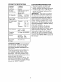
PRODUCT
SPECIFICATIONS
CUSTOMER
• Read and observe the safety
• Follow a regular schedule in
taining, caring for and using
• Follow the instructions
under
Gasoline
5 Gallons
Capacity
and Type:
Unleaded
Regular
Oil Type
(API-SG-SL):
SAE 30 (above
SAE 5W-30
(Below 32°F)
Oil Capacity:
W/Filter:
4.0 Pints
W/O Filter: 3.75 Pints
Spark Plug:
(Gap: .040")
Champion
Ground
(MPH):
Speed
RESPONSIBILITIES
32°F)
QC12YC
Forward:
1st
2nd
3rd
Reverse:
Lo:
0.7
1.4
2.3
0.9
Tire Pressure:
Front:
Rear:
Charging
System:
16 Amps
Battery:
Amp/Hr:
Min. CCA:
Case Size:
Blade Bolt
Torque:
45-55
Hi:
1.7
3.3
5.4
2.1
14 PSI
10 PSI
@ 3600RPM
35
280
U1R
Ft. Lbs.
CONGRATULATIONS
on your purchase
of a new tractor. It has been designed,
engineered
and manufactured
to give
you the best possible dependability
and
performance.
Should you experience
any problem you
cannot easily remedy, please contact
your nearest authorized
service center/
department.
We have competent,
welltrained technicians
and the proper tools to
service or repair this tractor.
Please read and retain this manual. The
instructions
will enable you to assemble
and maintain your tractor properly.
Always
observe the "SAFETY
RULES".
rules.
mainyour tractor.
"Mainte-
nance" and "Storage" sections of this
owner's manual.
,_WARNING:
This tractor is equipped
with an internal combustion
engine and
should not be used on or near any unimproved forest-covered,
brush-covered
or
grass-covered
land unless the engine's
exhaust system is equipped with a spark
arrester meeting applicable local or state
laws (if any). If a spark arrester is used, it
should be maintained
in effective working
order by the operator.
In the state of California the above is
required by law (Section 4442 of the
California Public Resources
Code). Other
states may have similar laws. Federal
laws apply on federal lands. A spark arrester for the muffler is available through
your nearest authorized
service center/department
(See REPAIR PARTS section of
this manual).
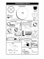
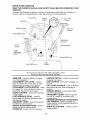
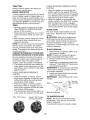
Steering Wheel
Steering
Sleeve
O
Wheel
teering
Adapter
_
Steering
Wheel
(1) Large Flat
Insert
Gauge
Nose
Wheels
1
f
Bar
(i) Adjusting
Roller
(2) LJcknuts_
0
(4) Retainer Springs
(double loop)
@
(4) Locknut
R_
Retainer
3/8-16
(4) Washers
3/8 x 3/4 x 14 Ga.
_O
!
(2) Hex Bolts
5/16-18 x 1
(4) Clevis Pins
Shoulder Bolt
(4)
(1) Oil Drain Tube
For Future Use
(4) Wheels
Slope
Sheet
Keys
Seat
(2) Keys
Mower
(1) Washer
@
17/32 x 1-3/16 x 12 Gauge
%
(2)
(1) Knob
7
Retainer Springs
(double loop)
(2)Flanged
Pins
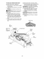
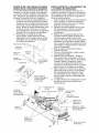
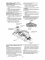
Your new tractor has been assembled
at the factory with the exception of those parts left
unassembled
for shipping purposes. To ensure safe and proper operation of your tractor
all parts and hardware you assemble must be tightened
securely. Use the correct tools
as necessary
to insure proper tightness. Review the video cassette before you begin.
TOOLS
REQUIRED
A socket wrench
easier. Standard
are listed below.
FOR
ASSEMBLY
set will make assembly
wrench sizes you need
(1) 3/4" wrench
(1) Pliers
(2) 7/16" wrench
(1) Utility knife
(1) Tire pressure
gauge
When right or left hand is mentioned
in
this manual, it means, from your point of
view, when you are in the operating position (seated behind the steering wheel).
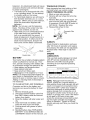
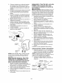
TO
REMOVE
Steering Wheel
TRACTOR
Nut
Large Flat
_5_
SteeringWheel__.
Steering
Shaft
_,,:i
Washer
_---------Wh
Steering
ee
....
Adaptor
FROM
CARTON
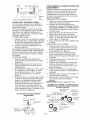
UNPACK
CARTON
1.
Remove all accessible
loose parts and
parts boxes from carton.
2. Cut along dotted lines on all four panels of carton. Remove end panels and
lay side panels flat.
3. Remove mower and packing materials.
4. Check for any additional loose parts or
cartons and remove.
BEFORE
REMOVING
FROM
SKID
ATTACH STEERING
1.
TRACTOR
WHEEL
Remove Iocknut and large flat washer
from steering shaft.
2. Position front wheels of the tractor so
they are pointing straight forward.
3. Slide the steering sleeve over the
steering shaft.
4. Position steering wheel so cross bars
are horizontal
(left to right) and slide
onto steering wheel adapter.
5. Secure steering wheel to steering
shaft with Iocknut and large flat washer
previously removed. Tighten securely.
6. Snap steering wheel insert into center
of steering wheel.
7. Remove protective materials from tractor hood and grill.
IMPORTANT:
Check for and remove any
staples in skid that may puncture tires
where tractor is to roll off skid.
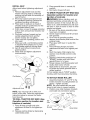
CHECK
BATTERY
1. Lift hood to raised position.
NOTE: If this battery is put into service
after month and year indicated on label
(label located between terminals) charge
battery for minimum
of one hour at 6-10
amps. (See "BATTERY"
in Maintenance
section of this manual for charging instructions).
Label
,
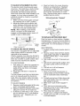
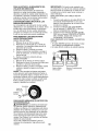
INSTALL
SEAT
3.
Adjust seat before tightening
adjustment
knob.
1. Remove adjustment
knob and flat
washer securing seat to cardboard
packing and set aside for assembly of
seat to tractor.
2. Pivot seat upward and remove from
the cardboard
packing. Remove the
cardboard
packing and discard.
3. Place seat on seat pan so head of
shoulder bolts are positioned
over the
large slotted holes in pan.
4. Push down on seat to engage shoulder
bolts in slots and pull seat towards rear
of tractor.
5. Pivot seat and pan forward and assemble adjustment
knob and flat
washer loosely. Do not tighten.
6. Lower seat into operating position and
sit in seat.
7. Slide seat until a comfortable
position
is reached which allows you to press
clutch/brake
pedal all the way down.
8. Get off seat without moving its adjusted position.
9. Raise seat and tighten adjustment
knob securely.
4.
Place gearshift lever in neutral
position.
Roll tractor forward off skid.
TO DRIVE
TRACTOR
OFF
Operation section for
_wACtion of controls)
(N)
SKID
location
(See
and
RNING: Before starting, read, understand and follow all instructions
in the
Operation section of this manual. Be sure
tractor is in a well-ventilated
area. Be sure
the area in front of tractor is clear of other
people and objects.
1. Be sure all the above assembly steps
have been completed.
2. Check engine oil level and fill fuel tank
with gasoline.
3. Sit on seat in operating position,
depress clutch/brake
pedal and set the
parking brake.
4. Place gear shift lever in neutral (N)
position.
5. Press lift lever plunger and raise
attachment
lift lever to its highest position.
6.
Start the engine. After engine has
started, move throttle control to idle
position.
7. Depress clutch/brake
pedal into full
"BRAKE" position and hold. Move
gearshift lever to 1st gear.
8. Slowly release clutch/brake
pedal and
slowly drive tractor off skid.
9. Apply brake to stop tractor, set parking brake and place gearshift lever in
neutral position.
10. Turn ignition key to "STOP" position.
Continue with the instructions
that follow.
Seat
Seat Pan
Shoulder
Bolts
Flat Washer
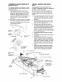
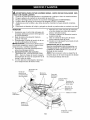
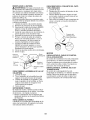
TO ATTACH NOSE ROLLER
1.
Operation
section
function
1.
2.
of
"A" and "B" to the
and install rod and retainer
NOTE: You may now roll or drive your
tractor off the skid. Follow the appropriate
instruction
below to remove the tractor
from the skid.
TRACTOR
brackets
inside of mower mounting brackets as
shown. Tighten securely.
NOTE:
Be sure bracket tabs are positioned in tab holes in mower brackets.
2. Position nose roller between brackets
Adjustment Knob
TO ROLL
Assemble
OFF
for
SKID
location
Lock
Nut
(See
Tab
Hole _
and
spring.
Hex Bolt
Rod
"B"
Bracket
controls)
Press lift lever plunger and raise
attachment
lift lever to its highest
sition.
po-
Release parking brake by depressing
clutch/brake
pedal.
Nose Roller
Retainer Spring
9
ASSEMBLE GAUGE WHEELS TO
MOWER DECK
INSTALL
BELT
The gauge wheels are designed to keep
the mower deck in proper position when
operating mower.
1. Slide gauge wheel bar down into
bracket channel, Be sure that gauge
wheel bar aligning holes are on top.
Assemble
gauge wheels as shown
using shoulder bolts, 3/8 washers and
3/8-16 center Iocknuts and tighten
securely.
2. For ease of mower to tractor assembly,
set all the gauge wheels in the fourth
hole from top. Retain with clevis pins
and spring retainers.
See MOWER
RetainerS
"
f
Adjusting
Bolt ____._.__ Bar_
Gauge
Wheel
3/8Washer
AND
AND DRIVE
DRIVE
BELT AS-
SEMBLY Supplement
Sheet for additional
guidance on this assembly.
Be sure tractor is on level surface and
mower suspension
arms are raised with
attachment
lift control. Engage parking
brake.
1. Turn steering wheel to the left as far as
it will go and position mower on right
side of tractor with deflector shield to
the right.
2. Remove plastic tie strap from mower
belt and check belt for proper routing
in all mower pulley grooves.
3. Slide mower under tractor until it is
centered
under tractor. DO NOT connect any pins. When properly centered
the front mower brackets should be
aligned so when the front suspension
plate is lowered it should slide between
the mower brackets.
4. Lower attachment
lift lever to lowest
position.
5. Cut plastic tie and lower front suspension plate.
6. ATTACH FRONT PLATE - From left
side of mower, position front plate assembly between front mower brackets,
align holes, position flanged pin notch
horizontally
and insert the pin all the
way. The notch is in line with the hole
in pin.
7. Secure pin with double loop retainer
spring between the plate and mower
bracket. If necessary, move mower
side-to-side
to give space between
Pin
Shoulder
MOWER
_.
_/3/8-16
Center
Locknut
All Wheels
To 4th Hole
From Top
g Bracket
Belt Tension
Rod
Disengaged
Position
Suspension
Arms
Electric Clutch Pulley
Front Plate Assembly
Mower Bracket
.,P
Double Loop
prings
Flanged Pin Position Notch
Horizontally
Gauge
Wheel
Rear Mower Pins
Deflector Shield
10
plate and mower bracket.
Go to right hand side of mower and
insert pin and retainer spring in the
same manner.
9. CONNECT
REAR PINS - Connect
right hand side first. Pull out and hold
the spring loaded pin, align hole in
suspension
arm and release pin. Be
sure pin returns to fully seated position
and is attached to the suspension
arm.
10. Go to left side of mower and connect
,/CHECKLIST
8.
Before you operate
your new tractor, we
wish to assure that you receive the best
performance
and satisfaction
from this
Quality Product.
Please review the following checklist:
,/All assembly instructions
have been
completed.
,/No remaining loose parts in carton.
,/Battery
is properly prepared and
charged.
(Minimum
1 hour at 6 amps).
rear pin in the same manner.
11. Disengage
belt tension rod.
12. From right side of tractor, install belt
onto engine clutch pulley.
IMPORTANT:
Check belt for proper routing in all mower pulley grooves.
13. Engage belt tension rod on locking
bracket.
_, CAUTION:
Belt tension rod is spring
loaded. Have a tight grip on rod and engage slowly.
14. Raise attachment
lift lever to highest
position.
15. Adjust gauge wheels before operating
mower as shown in the Operation section of this manual.
CHECK
TIRE
,/Seat
is adjusted comfortably
and tightened securely.
,/All tires are properly inflated.
(For shipping purposes, the tires were overinflated at the factory).
,/Be sure mower deck is properly leveled
side-to-side/front-to-rear
for best cutting
results.
(Tires must be properly inflated
for leveling).
,/Check
mower and drive belts. Be sure
they are routed properly around
and inside all belt keepers.
,/Check
wiring. See that all connections
are still secure and wires are properly
clamped.
While learning how to use your tractor, pay
extra attention to the following important
items:
PRESSURE
The tires on your tractor were overinflated
at the factory for shipping purposes.
Correct tire pressure is important for best
cutting performance.
• Reduce tire pressure to PSI shown in
"PRODUCT
SPECIFICATIONS"
section
of this manual.
CHECK
DECK
,/Engine
LEVELNESS
CHECK
FOR
OF ALL
BELTS
section
,/Be sure brake system
ing condition.
POSITION
manual).
See the figures that are shown for replacing motion and mower blade drive belts
in the Service and Adjustments
section
of this manual. Verify that the belts are
routed correctly.
CHECK
BRAKE
is in safe operat-
,/Be sure Operator Presence System
and Reverse Operation System (ROS)
are working properly (See the Operation and Maintenance
sections in this
of this manual.
PROPER
oil is at proper level.
,/Fuel
tank is filled with fresh, clean, regular unleaded gasoline.
,/Become
familiar with all controls, their
location and function.
Operate them
before you start the engine.
For best cutting results, mower housing
should be properly leveled. See "TO LEVEL MOWER HOUSING"
in the Service
and Adjustments
pulleys
SYSTEM
After you learn how to operate your tractor, check to see that the brake is properly
adjusted.
See "TO ADJUST BRAKE" in
the Service and Adjustments
section of
this manual.
11
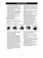
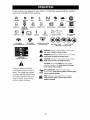
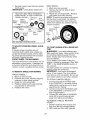
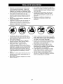
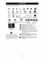
These symbols may appear on your tractor
Learn and understand
their meaning.
R
N
REVERSE
NEUTRAL
or in literature
H
supplied
with the product.
I'.,I
HIGH
LOW
CHOKE
SLOW
FAST
IGNITION SWITCH
6
G
ENGINE OFF
REVERSE
OPERATION
SYSTEM (ROS)
ENGINE ON
(®)
ENGINE START
PARKING
BRAKE
MOWER HEIGHT
MOWER LIFT
t
LIGHTS ON
FUEL
BATTERY
REVERSE
FORWARD
CRUISE CONTROL
CLUTCH/BRAKE
PEDAL
®@@@@
ATTACHMENT
CLUTCH DISENGAGED
ATTACHMENT
CLUTCH ENGAGED
DANGER, KEEP HANDS
AND FEET AWAY
KEEP AREA CLEAR
SLOPE HAZARDS
(SEE SAFETY RULES SECTION)
DANGER
if not avoided,
will
result indicates
in death aorhazard
seriouswhich,
injury.
WARNING
hazard
which,
if not avoided
could resultindicates
in deatha or
serious
injury.
FREEWHEEL
(Automatic
Modelsonly)
CAUTION indicates a hazard which, if not avoided
might result in minor or moderate injury.
&
CAUTION when used without the alert symbol,
indicates a situation that could result in damage
to the tractor and/or engine.
Failure to follow instructions
could result in serious injury or
death. The safety alert symbol
is used to identify safety information about hazards which can
result in death, serious injury
and/or property damage.
41_lIlllll_lll.,
HOT SURFACES indicates a hazard which,
if not avoided, could result in death, serious injury
and/or property damage.
FIRE indicates a hazard which, if not avoided,
could result in death, serious injury and/or
property damage.
12
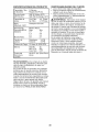
KNOW
YOUR
READ THIS
TRACTOR
TRACTOR
OWNER'S
MANUAL
AND SAFETY
RULES
BEFORE
OPERATING
Compare the illustrations
with your tractor to familiarize yourself with the locations
various controls and adjustments.
Save this manual for future reference.
Hourmeter
Ammeter
Ignition
Switch
YOUR
of
Ros "ON"
Position
Attachment
Clutch Switch
Throttle Control
Clutch/Brake
Lift Lever
Plunger
Pedal
Attachment
Lift Lever
Choke
Control
Parking Brake
Height
Adjustment
Range Shift Lever
/
Gear Shift Lever
Light
Switch
02825
LSW_
Our tractors conform to the safety standards
American
National Standards
Institute.
AMMETER
- Indicates battery charging
(+) or discharging
(-).
ATTACHMENT
LIFT LEVER - Used to
raise and lower the mower deck or other
of the
IGNITION SWITCH - Used for starting and
stopping the engine.
LIGHT SWITCH - Turns the headlights
on
and off.
LIFT LEVER PLUNGER
- Used to release
attachments
mounted to your tractor.
ATTACHMENT
CLUTCH
SWITCH - Used
attachment
position.
PARKING
to engage the mower blades, or other attachments
mounted to your tractor.
CHOKE CONTROL
- Used when starting
a cold engine.
CLUTCH/BRAKE
PEDAL - Used for
lift lever when changing
BRAKE
- Locks
its
clutch/brake
into the brake position.
RANGESHIFT
LEVER - Allows high (H)
and low (L) speed for all forward and
reverse gears.
REVERSE
OPERATION
SYSTEM (ROS)
"ON" POSlTON
- Allows operation of
mower deck or other powered attachment
while in reverse.
THROTTLE
CONTROL
- Used to control
declutching
and braking the tractor and
starting the engine.
GEARSHIFT
LEVER - Selects the speed
and direction of the tractor.
HEIGHT ADJUSTMENT
KNOB - Used to
adjust the mower cutting height.
HOURMETER - Indicates hours of operation.
engine
13
speed.
The operation of any tractor can result in foreign objects thrown into
the eyes, which can result in severe eye damage.
Always wear safety
glasses or eye shields while operating your tractor or performing
any
adjustments
or repairs.
We recommend
standard safety glasses or a
wide vision safety mask worn over spectacles.
SAFETYGLASSES
• Never use choke to stop engine.
IMPORTANT:
Leaving the ignition switch
in any position other than "STOP" will
cause the battery to discharge and go
dead.
NOTE:
Under certain conditions when
HOW TO USE YOUR TRACTOR
TO SET PARKING
BRAKE
Your tractor is equipped
with an operator
presence sensing
switch. When engine
is running, any attempt by the operator
to leave the seat without first setting the
parking brake will shut off the engine.
1. Depress clutch/brake
pedal all the way
down and hold.
2.
tractor is standing idle with the engine
running, hot engine exhaust gases may
cause "browning"
of grass. To eliminate
this possibility, always stop engine when
stopping tractor on grass areas.
Pull parking brake lever up and release
pressure from clutch/brake
pedal.
Pedal should remain in brake position.
Make sure parking brake will hold tractor secure.
Push-In to
"Disengaged"
Attachment Clutch
Choke
Switch Pull Out To
"Engage"
,_LCAUTION:
TO USE THROTTLE
,/
/
nitior
Key
TO USE CHOKE
Brake
Clutch/
"Engaged"
Brake Pedal
gaged"
Position
"Drive"
Position
Gear Shift
Position
Height Adjustment
Lever
Knob
STOPPING
BLADES
DRIVE
-
-
• Move throttle
control
between
full speed (fast) position.
NOTE:
Failure to move throttle
half and
CONTROL
of your transaxle.
TO ADJUST
MOWER
control
CUTTING
The cutting height is controlled
ing the height adjustment
knob
direction.
• Turn knob clockwise (_)
to
ting height.
• Turn knob counterclockwise
between half and full speed (fast) position, before stopping, may cause engine
to "backfire".
• Turn ignition key to "STOP" position and
remove key. Always remove key when
leaving tractor to prevent unauthorized
use.
CONTROL
The direction and speed of movement
is
controlled
by the gearshift
lever.
1. Start tractor with clutch/brake
pedal depressed and gearshift lever in neutral
(N) position.
2. Move gearshift and range shift levers
to desired position.
3. Slowly release clutch/brake
pedal to
start movement.
IMPORTANT:
Bring tractor to a complete
stop before shifting or changing gears.
Failure to do so will shorten the useful life
-
• To stop ground drive, depress clutch/
brake pedal all the way down.
• Move gearshift
lever to neutral (N)
position.
ENGINE
comleaving
BACKWARD
• To stop mower blades, push attachment
clutch switch in to disengaged
position.
GROUND
before
Use choke control whenever you are starting a cold engine. Do not use to start a
warm engine.
• To engage choke control, pull knob out.
Slowly push knob in to disengage.
TO MOVE FORWARD
AND
g_
MOWER
stop tractor
Always operate engine at full throttle.
• Operating engine at less than full
throttle reduces the battery charging
rate.
• Full throttle offers the best mower performance.
Throttle
Control
"Brake"
Always
pletely, as described
above,
the operator's
position.
14
lower cutting
height.
HEIGHT
by turnin desired
raise cut(l_-_)
to
The cutting height range is approximately
1-1/2" to 4-1/2". The heights are measuredfrom the ground to the bladetip with
the engine not running.
TO OPERATE
Your tractor is equipped with an operator
presence sensing switch. Any attempt
by the operator to leave the seat with the
engine running and the attachment
clutch
engaged will shut off the engine. You must
remain fully and centrally positioned
in the
seat to prevent the engine from hesitating
or cutting off when operating your equipment on rough, rolling terrain or hills.
1. Select desired height of cut.
2. Lower mower with attachment
lift control.
These heights are approximate
and may
vary depending
upon soil conditions,
height of grass and types of grass being
mowed.
• The average lawn should be cut to
approximately
2-1/2 inches during the
cool season and to over 3 inches during
hot months.
For healthier and better
looking lawns, mow often and after moderate growth.
• For best cutting performance,
grass over
6 inches in height should be mowed
twice. Make the first cut relatively high;
the second to desired height.
TO ADJUST
GAUGE
3.
Start mower blades by engaging
tachment clutch control.
TO STOP MOWER BLADES -
WHEELS
Low
Position
,:_!J
Deflector
Shield
1.
Retainer
Spring
at-
disengage
attachment
clutch control.
AI, CAUTION:
Do not operate the mower
without either the entire grass catcher,
on mowers so equipped,
or the deflector
shield in place.
Attachemnt Lift
Attachment Clutch
Lever High Position
Switch Pull Out to
"Engage"
Gauge wheels
are properly adjusted
when they are slightly off the ground when
mower is at the desired cutting height in
operating position. Gauge wheels then
keep the deck in proper position to help
prevent scalping in most terrain conditions.
NOTE: Be sure tractor is on a flat level
surface.
Lower mower and adjust mower to
desired cutting height.
2. Remove retainer spring and clevis pin
which secure each gauge wheel bar.
3. Lower gauge wheels to ground. Raise
gauge wheels slightly to align holes
in bracket and gauge wheel bar and
insert clevis pin. Gauge wheels should
be slightly off the ground.
4. Replace retainer spring into clevis pin.
5. Be sure all gauge wheels are in the
same setting.
IMPORTANT:
Be sure to readjust gauge
wheels if you change the cutting height
of the mower deck.
MOWER
Push-In to
"Disengage"
REVERSE OPERATION
SYSTEM (ROS)
Your tractor is equipped with a Reverse
Operation
System (ROS). Any attempt by
the operator to travel in the reverse direction with the attachment
clutch engaged
will shut off the engine unless ignition key
is placed in the ROS "ON" position.
_IWARNING:
Backing up with the attachment clutch engaged while mowing
is strongly discouraged.
Turning the ROS
"ON", to allow reverse operation with the
attachment
clutch engaged, should only
be done when the operator decides it is
necessary
to reposition the machine with
the attachment
engaged. Do not mow in
reverse unless absolutely
necessary.
Clevis
Pin
15
USING THE
SYSTEM -
REVERSE
OPERATION
1.
Depress clutch/brake
down and hold.
2.
With engine running, turn ignition key
counterclockwise
to ROS "ON" position.
3.
4.
Look down and behind before backing.
Move gear shift lever to reverse (R) position and slowly release clutch/brake
pedal to start movement.
When use of the ROS is no longer
needed, turn the ignition key clockwise
to engine "ON" position.
5.
ROS "ON" Position
TO TRANSPORT
• Raise attachment
lift to highest
with attachment
lift control.
pedal all the way
• When pushing or towing your tractor,
be sure gearshift lever is in neutral (N)
position.
• Do not push or tow tractor at more than
five (5) MPH.
NOTE: To protect hood from damage
when transporting
your tractor on a truck
or a trailer, be sure hood is closed and
secured to tractor. Use an appropriate
means of tying hood to tractor (rope, cord,
etc.).
TOWING
MENTS
Engine "ON" Position
(Normal Operating)
CARTS
AND
OTHER
ATTACH-
Tow only the attachments
that are recommended by and comply with specifications
of the manufacturer
of your tractor. Use
common sense when towing. Too heaw
of a load, while on a slope, is dangerous.
Tires can lose traction with the ground and
cause you to lose control of your tractor.
BEFORE
TO OPERATE
position
CHECK
ON HILLS
STARTING
ENGINE
THE
ENGINE
OIL LEVEL
The engine in your tractor has been
shipped, from the factory, already filled
with summer weight oil.
1. Check engine oil with tractor on level
ground.
2. Remove oil fill cap/dipstick
and wipe
clean, reinsert the dipstick and screw
cap tight, wait for a few seconds, remove and read oil level. If necessary,
add oil until "FULl" mark on dipstick is
reached.
Do not overfill.
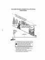
,_WARNING:
Do not drive up or down
hills with slopes greater than 15 ° and do
not drive across any slope. Use the slope
guide provided at the back of this manual.
• Choose the slowest speed before starting up or down hills.
• Avoid stopping or changing speed on
hills.
• If slowing is necessary,
move throttle
control lever to slower position.
• If stopping is absolutely necessary,
push
clutch/brake
pedal quickly to brake position and engage parking brake.
• Move gearshift lever to 1st gear and
range shift lever to low (L) position.
Be
sure you have allowed room for tractor
to roll slightly as you restart movement.
• To restart movement,
slowly release
parking brake and clutch/brake
pedal.
• Make all turns slowly.
• For cold weather operation you should
change oil for easier starting (See the
oil viscosity chart in the Maintenance
section of this manual).
• To change engine oil, see the Maintenance section in this manual.
16
ADD
GASOLINE
NOTE: Before starting, read the warm and
cold starting procedures
below.
6. Insert key into ignition and turn key
clockwise to start position and release
key as soon as engine starts. Do
not run starter continuously
for more
than fifteen seconds per minute. If the
engine does not start after several
attempts, push choke control in, wait
a few minutes and try again. If engine
still does not start, pull the choke control out and retry.
WARM WEATHER
STARTING (50 ° F and
above)
7. When engine starts, slowly push choke
control in until the engine begins to
run smoothly. If the engine starts to
run roughly, pull the choke control out
slightly for a few seconds and then
continue to push the control in slowly.
• The attachments
and ground drive can
now be used. If the engine does not
accept the load, restart the engine and
allow it to warm up for one minute using
the choke as described above.
COLD WEATHER
STARTING (50 ° F and
below)
7. When engine starts, slowly push choke
control in until the engine begins to run
smoothly. Continue to push the choke
control in small steps allowing the engine to accept small changes in speed
and load, until the choke control is fully
in. If the engine starts to run roughly,
pull the choke control out slightly for a
few seconds and then continue to push
the control in slowly. This may require
an engine warm-up period from several
seconds to several minutes, depending
on the temperature.
• The attachments
can be used during
the engine warm-up period and may
require the choke control be pulled out
slightly.
NOTE: If at a high altitude (above 3000
feet) or in cold temperatures
(below 32 F)
the carburetor
fuel mixture may need to
be adjusted for best engine performance
(see "TO ADJUST CARBURETOR"
in the
Service and Adjustments
section of this
manual).
• Fill fuel tank to bottom of filler neck. Do
not overfill. Use fresh, clean, regular
unleaded gasoline with a minimum of
87 octane. (Use of leaded gasoline will
increase carbon and lead oxide deposits
and reduce valve life). Do not mix oil
with gasoline.
Purchase fuel in quantities that can be used within 30 days to
assure fuel freshness.
_CAUTION:
Wipe off any spilled oil or
fuel. Do not store, spill or use gasoline
near an open flame.
IMPORTANT:
When operating in temperatures below32°F(0°C),
use fresh, clean
winter grade gasoline to help insure good
cold weather starting.
CAUTION:
Alcohol blended fuels (called
gasohol or using ethanol or methanol)
can
attract moisture which leads to separation and formation of acids during storage.
Acidic gas can damage the fuel system
of an engine while in storage. To avoid
engine problems, the fuel system should
be emptied before storage of 30 days
or longer. Drain the gas tank, start the
engine and let it run until the fuel lines
and carburetor
are empty. Use fresh fuel
next season. See Storage Instructions
for
additional information.
Never use engine
or carburetor
cleaner products in the fuel
tank or permanent
damage may occur.
TO START
ENGINE
When starting the engine for the first time
or if the engine has run out of fuel, it will
take extra cranking time to move fuel from
the tank to the engine.
1. Sit on seat in operating position,
depress clutch/brake
pedal and set
parking brake.
2. Place gear shift lever in neutral (N)
position.
3. Move attachment
clutch to disengaged
position.
4. Move throttle control to fast position
5. Pull choke control out for a cold engine
start attempt. For a warm engine start
attempt the choke control may not be
needed.
17
MOWING
TIPS
• Tire chains
cannot
be used when
• If grass is extremely tall, it should be
mowed twice to reduce load and possible fire hazard from dried clippings.
Make first cut relatively high; the second
to the desired height.
• Do not mow grass when it is wet.
Wet grass will plug mower and leave
undesirable
clumps.
Allow grass to dry
before mowing.
• Always operate
engine at full throttle
when mowing
to assure better mowing performance
and proper discharge
of material.
Regulate ground speed by
selecting a low enough gear to give the
mower cutting performance
as well as
the quality of cut desired.
• When operating attachments,
select a
ground speed that will suit the terrain
and give best performance
of the attachment being used.
the
mower housing is attached to tractor.
• Mower should be properly leveled for
best mowing performance.
See "TO
LEVEL MOWER HOUSING"
in the
Service and Adjustments
section of this
manual.
• The left hand side of mower should be
used for trimming.
• Drive so that clippings are discharged
onto the area that has already been
cut. Have the cut area to the right of
the tractor. This will result in a more
even distribution
of clippings and more
uniform cutting.
• When mowing large areas, start by
turning to the right so that clippings will
discharge away from shrubs, fences,
driveways, etc. After one or two rounds,
mow in the opposite direction making
left hand turns until finished.
)1
00272
18
.A,NTENANOE
SC.EOULE
FILL IN DATES
A SY O UC 0 M PLETE
J__'_
REGOLAR
SERVICE
Check
Operation
Check Brake
Tire Pressure
Check Operator
ROS Systems
R
Check
A
Sharpen/Replace
Presence
and
C
Lubrication
0
Check Battery
Level
1_4
R
Clean
and Terminals
tf
V'
for Loose Fasteners
Mower
If
V'5
Blades
Check Transaxle
V _
If
Vie
,/
Cooling
Check V-Belts
If
Oil Level
If
Change
Engine
Oil (with oil filter)
E
Change
Engine
Oil (without oil filter)
N
Clean Air
G
Clean Air Screen
N_
Inspect
E
Replace
Clean
11_1,2
Muffler/Spark
1_2
,/
Arrester
Oil Filter (If equipped)
Cooling
1_1,2
Fins
I1_ 2
Spark
Plug
Replace
Air Filter Paper Cartridge
Replace
Fuel Filter
1 - Change more often when operating
in high ambient temperatures.
2 - Service more often when operating
V'
_'
under
a heavy
load or
in dirty or dusty
3 - Replace
blades more often when mowing
in sandy soil.
4 - Not required
if equipped
with maintenance-tree
battery.
5 - Tighten
front axle pivot bolt to 35 ft.-Ibs, maximum.
Do not overtighten.
conditions.
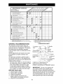
LUBRICATION
RECOMMENDATIONS
@ Spindle
Zerk
/_ii
_
@Front WheelBearing zerk
'_'",_
/_
Zerk
@Front
Wheel
_:_'_ _.____,.ea
ri ng ze rE
_(3)
Engine
@ Mandrel
Zerks
r_
@ Steerin_
Sector Gear
At least once a season, check to see if
you should make any of the adjustments
described
in the Service and Adjustments
section of this manual.
• At least once a year you should replace
the spark plug, clean or replace air filter,
and check blades and belts for wear.
CHART
@ Spindle ---_
Some adjustments
will need to be made
periodically
to properly maintain your
tractor.
;:[
Teeth
_SAE
I
4\_2
J _o_
30 or 10w30
\:_'"
I I I
) Check/Add
J I Transaxle
Fluid
Motor Oil
@General Purpose Grease
(3)Refer to Maintenance
"ENGINE"
A new spark plug and clean air filter
assure proper air-fuel mixture and help
your engine run better and last longer.
Section
IMPORTANT:
Do not oil or grease the
pivot points which have special nylon
bearings.
Viscous lubricants will attract
dust and dirt that will shorten the life of the
BEFORE EACH USE
5.
V'
_2
The warranty on this tractor does not
cover items that have been subjected to
operator abuse or negligence.
To receive
full value from the warranty, operator
must maintain tractor as instructed
in this
manual.
1.
2.
3.
4.
I_
_1_1,2
_1# 2
Replace
GENERAL
I_
Filter
Engine
V _
1_3
Chart
Check Engine
OATES
_V'
T
Battery
_.,_"
," TSERV'CE
Check engine oil level.
Check brake operation.
Check tire pressure.
Check operator presence and
ROS systems for proper operation.
Check for loose fasteners.
self-lubricating
bearings.
If you feel they
must be lubricated,
use only a dry, powdered graphite type lubricant sparingly.
19
TRACTOR
Alwaysobserve safety ruleswhen performing any maintenance.
BRAKE OPERATION
If tractor requiresmore than five (5) feet to
stop at highest speed in highest gear on a
level,dry concreteor paved surface,then
brakemust be checked and adjusted.(See
"TOADJUST BRAKE"in the Service and
Adjustmentssection of this manual).
TIRES
• Maintain proper air pressure in all tires
(See "PRODUCT
SPECIFICATIONS"
section of this manual).
• Keep tires free of gasoline, oil, or insect
control chemicals
which can harm rubber.
OPERATION
SYSTEM
mower
blades
must be
kept sharp. Replace bent or damaged
blades.
A CAUTION:
Use only a replacement
blade approved by the manufacturer
of
your tractor. Using a blade not approved
by the manufacturer
of your tractor is
hazardous,
could damage your tractor and
void your warranty.
BLADE
REMOVAL
1.
Raise mower to highest position to allow access to blades.
NOTE: Protect your hands with gloves
and/or wrap blade with heavy cloth.
2. Remove blade bolt by turning counterclockwise.
3. Install new or resharpened
blade with
stamped "THIS SIDE UP" facing deck
and mandrel assembly.
IMPORTANT:
To ensure proper assembly,
center hole in blade must align with star
on mandrel assembly.
4. Install and tighten blade bolt securely
(45-55 Ft. Lbs. torque).
IMPORTANT:
Special blade bolt is heat
treated.
(ROS)
PRESENCE
• When the engine is running, any attempt by the operator to leave the seat
without first setting the parking brake
should shut off the engine.
• When the engine is running and the
attachment
clutch is engaged, any attempt by the operator to leave the seat
should shut off the engine.
• The attachment
clutch should never operate unless the operator is in the seat.
ROS "ON" Position
(ROS)
CARE
For best results
Be sure operator presence and reverse
operation systems are working properly.
If
your tractor does not function as described, repair the problem immediately.
• The engine should not start unless the
brake pedal is fully depressed,
and the
attachment
clutch control is in the disengaged position.
CHECK OPERATOR
SYSTEM
OPERATION
• When the engine is running with the
ignition switch in the engine "ON" position and the attachment
clutch engaged,
any attempt by the operator to shift into
reverse should shut off the engine.
• When the engine is running with the
ignition switch in the ROS "ON" position
and the attachment
clutch engaged,
any attempt by the operator to shift into
reverse should NOT shut off the engine.
BLADE
• Avoid stumps, stones, deep ruts, sharp
objects and other hazards that may
cause tire damage.
NOTE: To seal tire punctures and prevent
flat tires due to slow leaks, tire sealant
may be purchased
from your local parts
dealer. Tire sealant also prevents tire dry
rot and corrosion.
OPERATOR
PRESENCE
SYSTEM AND
REVERSE
CHECK REVERSE
SYSTEM
Mandrel
Blade
Center Hole
J
Blade Bolt (Special)
TO SHARPEN
Engine "ON" Position
(Normal Operating)
BLADE
NOTE: We do not recommend
sharpening blade - but if you do, be sure the
blade is balanced.
Care should
20
be taken to keep the blade
y
balanced.
An unbalanced
blade will cause
TRANSAXLE
excessive vibration and eventual damage
to mower and engine.
• The blade can be sharpened
with a file
or on a grinding wheel. Do not attempt
to sharpen while on the mower.
• To check blade balance, you will need a
5/8" diameter steel bolt, pin, or a cone
balancer.
(When using a cone balancer,
follow the instructions
supplied with
balancer.)
NOTE:
Do not use a nail for balancing
blade. The lobes of the center hole may
appear to be centered,
but are not.
• Slide blade on to an unthreaded
portion
of the steel bolt or pin and hold the
bolt or pin parallel with the ground.
If
blade is balanced,
it should remain in a
horizontal position.
If either end of the
blade moves downward,
sharpen the
heavy end until the blade is balanced.
COOLING
Keep transaxle free from build-up of dirt
and chaff which can restrict cooling.
CHECK TRANSAXLE
OIL LEVEL
1.
2.
Block up rear axle securely.
Remove left rear wheel by removing
hub bolts.
3.
Remove filler plug from transaxle.
Oil
level must be even with plug threads.
If necessary,
fill with SAE 30 motor oil,
API SG-SL. Replace filler plug.
Reassemble
wheel to hub.
4.
_
.Transaxle Filler
V-BELTS
Check V-belts
for deterioration
and wear
after 100 hours of operation and replace
if necessary. The belts are not adjustable.
Replace belts if they begin to slip from
wear.
5/8" Bolt
ENGINE
Center Hole
LUBRICATION
BATTERY
Only use high quality detergent oil rated
with API service classification
SG-SL.
Select the oil's SAE viscosity grade
according to your expected operating
temperature.
Your tractor has a battery charging system
which is sufficient for normal use. However, periodic charging of the battery with
an automotive
charger will extend its life.
• Keep battery and terminals clean.
• Keep battery bolts tight.
• Keep small vent holes open.
• Recharge
at 6-10 amperes for 1 hour.
NOTE: The original equipment
battery on
your tractor is maintenance
free. Do not
attempt to open or remove caps or covers.
Adding or checking level of electrolyte
is
not necessary.
TO CLEAN
BATTERY
SAE VISCOSITY
4O
oi_ visc
AND TERMINALS
section
of this manual).
cha_tl
NOTE: Although multi-viscosity
oils
(5W30, 10W30 etc.)improve
starting in
cold weather, these multi-viscosity
oils will
result in increased oil consumption
when
used above 32°R Check your engine oil
level more frequently to avoid possible
engine damage from running low on oil.
Change the oil after every 50 hours of operation or at least once a year if the tractor
is not used for 50 hours in one year.
Check the crankcase
oil level before starting the engine and after each eight (8)
hours of operation.
Tighten oil fill cap/
dipstick securely each time you check the
oil level.
Corrosion and dirt on the battery and
terminals can cause the battery to "leak"
power.
1. Remove terminal guard.
2. Disconnect
BLACK battery cable first
then RED battery cable and remove
battery from tractor.
3. Rinse the battery with plain water and
dry.
4. Clean terminals and battery cable
ends with wire brush until bright.
5. Coat terminals with grease or petroleum jelly.
6. Reinstall battery (See "REPLACING
BATTERY" in the SERVICE AND ADJUSTMENTS
GRADES
21
e
TO CHANGEENGINEOIL
Determinetemperaturerange expected
beforeoil change. All oil must meet API
serviceclassificationSG-SL.
• Be sure tractoris on level surface.
• Oil will drain more freely when warm.
• Catchoil in a suitablecontainer.
1. Removeoil fill cap/dipstick. Be careful
not to allow dirt to enter the engine
when changing oil.
2. Installthe drain tube onto the valve.
3. Open drain valve by using a 7/16"
(11mm)wrench turning counterclockwise.
Oil DrainValve
AIR
FILTER
Your engine will not run properly using
a dirty air filter. Service air cleaner more
often under dusty conditions.
See Engine
Manual.
ENGINE
Replace the engine oil filter every season
or every other oil change if the tractor is
used more than 100 hours in one year.
MUFFLER
Inspect and replace corroded muffler and
spark arrester (if equipped)
as it could create a fire hazard and/or damage.
SPARK PLUG(S)
Replace spark plug(s) at the beginning
of each mowing season or after every
100 hours of operation,
whichever occurs
first. Spark plug type and gap setting are
shown in "PRODUCT
SPECIFICATIONS"
section of this manual.
To Open
To Close
IN-LINE
Drain Tube
4.
5.
6.
7.
FUEL
FILTER
The fuel filter should be replaced once
each season.
If fuel filter becomes
clogged, obstructing
fuel flow to carburetor, replacement
is required.
1. With engine cool, remove filter and
plug fuel line sections.
2. Place new fuel filter in position in fuel line
with arrow pointing towards carburetor.
3. Be sure there are no fuel line leaks
After oil has drained completely,
close
the drain valve turning clockwise. Use
the 7/16" (11 mm) wrench to apply
a small amount of torque to keep it
closed. Do not over tighten.
Remove the drain tube and store in a
safe place.
Refill engine with oil through oil fill dipstick tube. Pour slowly. Do not overfill.
For approximate
capacity see "PRODUCT SPECIFICATIONS"
section of this
manual.
4.
and clamps
Immediately
line.
are properly positioned.
wipe up any spilled gaso-
oamp
Use gauge on oil fill cap/dipstick
for
checking level.
For accurate reading,
tighten dipstick cap securely onto the
tube before removing dipstick.
Keep oil
at "FULl" line on dipstick. Tighten cap
onto the tube securely when finished.
CLEAN
OIL FILTER
CLEANING
• Clean engine, battery, seat, finish, etc.
of all foreign matter.
• Keep finished surfaces and wheels free
of all gasoline, oil, etc.
• Protect painted surfaces with automotive type wax.
We do not recommend
using a garden
hose or pressure washer to clean your
tractor unless the engine and transmission are covered to keep water out. Water
in engine or transmission
will shorten the
useful life of your tractor. Use compressed
air or a leaf blower to remove grass,
leaves and trash from tractor and mower.
AIR SCREEN
Air screen must be kept free of dirt and
chaff to prevent engine damage from
overheating.
Clean with a wire brush or
compressed
air to remove dirt and stubborn dried gum fibers.
22
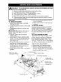
WARNING:
TO AVOID SERIOUS
VICE OR ADJUSTMENTS:
INJURY,
BEFORE
PERFORMING
ANY SER-
1. Depress clutch/brake
pedal fully and set parking brake.
2. Place gearshift lever in neutral (N) position.
3. Place attachment
clutch in "DISENGAGED"
position.
4. Turn ignition key to "STOP" and remove key.
5. Make sure the blades and all moving parts have completely
stopped.
6. Disconnect
spark plug wire from spark plug and place wire where it cannot
come in contact with plug.
TRACTOR
TO
1.
2.
3.
,_
REMOVE
9.
Turn tractor steering wheel to the left
as far as it will go.
10.Slide mower out from under right side
of tractor.
TO INSTALL
MOWER
MOWER
Place attachment
clutch
in "DISEN-
GAGED" position.
Lower attachment
lift lever to its lowest
position.
Disengage
belt tension rod from lock
bracket.
CAUTION:
Belt tension rod is spring
Follow procedure described
in "INSTALL
MOWER AND DRIVE BELT" in the Assembly section of this manual. NOTE: You
will need to reattach front plate assembly
to tractor after sliding mower under the
tractor.
loaded. Have a tight grip on rod and
release slowly.
4. Remove mower belt from electric
TO LEVEL
5.
clutch pulley.
DISCONNECT
6.
FIRST - Pull out the spring loaded pin,
disconnect
suspension
arm from pin
and release pin.
Go to other side of mower and discon-
7.
8.
REAR
MOWER
MOWER
HOUSING
Adjust the mower while tractor is parked
on level ground or driveway.
Make sure
tires are properly inflated (See "PRODUCT SPECIFICATIONS"
section of this
PINS
manual).
If tires are over or underinflated,
you will not properly adjust your mower.
nect rear pin in the same manner.
Remove the four retainer springs and
two flanged pins from front plate assembly and remove plate.
Raise attachment
lift lever to its highest
position.
SIDE-TO-SIDE
ADJUSTMENT
• Raise mower to its highest position.
• Measure height from bottom edge of
mower to ground level at front corners
of mower. Distance "A" on both sides of
mower should be the same.
g Bracket
Electric Clutch Pulley
Belt Tension Rod
Disengaged Position
Front Plate Assembly
Single Loop
#j
Retainer Springs
Double Loop
Retainer Springs
Flanged Pin
Rear Mower Pins
23
NOTE:
• If adjustment
is necessary,
make adjustment on one side of mower only.
• To raise one side of mower, tighten lift
link adjustment
nut on that side.
• To lower one side of mower, loosen lift
link adjustment
nut on that side.
NOTE:
Each full turn of adjustment
nut
will change mower height about 3/16".
• Recheck measurements
after adjusting.
Bottom Edge of
Mower to Ground
Each full turn of nut "C" will
change distance "B" by approximately
3/16".
• When distance "B" is 1/8" to 1/2" lower
at front than rear, tighten nut "D" against
trunnion on both front links.
• To raise front of blade, loosen nut
"D" from trunnion on both front links.
Tighten nut "C" on both front links an
equal number of turns. The two front
links must remain equal in length.
• When distance "B" is 1/8" to 1/2" lower
Bottom Edge of
Mower to Ground
at front than rear, tighten nut "D" against
trunnion on both front links.
• Recheck side-to-side
adjustment.
Blade
Suspension
Arm
_a
BOTH FRONT PLATE LINKS MUST BE
EQUAL IN LENGTH
Eift Link
ustment
Nut
FRONT-TO-BACK
IMPORTANT:
_
ADJUSTMENT
Deck must be level side-
to-side.
If the following front-to-back
adjustment
is necessary, be sure to adjust
both front links equally so mower will stay
level side-to-side.
To obtain the best cutting results, the
mower blades should be adjusted so the
front tip is approximately
1/8" to 1/2" lower
than the rear tip when the mower is in its
highest position.
CAUTION:
Blades are sharp. Protect
your hands with gloves and/or wrap blade
with heavy cloth.
Check adjustment
on right side of tractor.
Position any blade so the tip is pointing
straight forward. Measure distance "B" at
front and rear tip of blade
• Before making any necessary
adjustments, check that both front plate links
are equal in length.
• If links are not equal in length, adjust
one link to same length as other link.
• To lower front of blade, loosen nut "C"
on both front links an equal number of
turns.
•N ut "C"
Trunnion
24
TO REPLACE
MOWER
MOWER
DRIVE
DRIVE
BELT
MOWER
DRIVE
BELT INSTALLATION
1.
Install belt around both mandrel pulleys
and around idler pulleys as shown.
2. Install belt onto electric clutch pulley.
IMPORTANT:
Check belt for proper routing in all mower pulley grooves.
3. Reassemble
R.H. and L.H. mandrel
BELT REMOVAL
1.
Park tractor on a level surface. Engage
parking brake.
2. Lower attachment
lift lever to its lowest
position.
3. Disengage
belt tension rod from lock
Abracket.
CAUTION:
Belt tension rod is spring
loaded. Have a firm grip on rod and release slowly.
4. Remove screws from R.H. and L.H.
mandrel covers and remove covers.
5.
Remove any dirt or grass clippings
which may have accumulated
around
mandrels and entire upper deck surface.
6.
Remove belt from electric clutch pulley,
both mandrel pulleys and all idler pulleys.
4.
covers. Securely tighten all screws.
Engage belt tension rod on locking
bracket.
A CAUTION:
Belt tension rod is spring
loaded. Have a tight grip on rod and engage slowly.
5. Raise attachment
lift lever to highest
position.
Belt Routing
L.H.
Mandrel
Cover
Belt Tension
Rod
(Disengaged
Locking Bracket
Electric
Clutch
Pulley
Position)
R.H.
Mandrel
Cover
R.H.
Mandrel
Idler
Pulleys
25
TO ADJUST
ATTACHMENT
CLUTCH
,
The electric clutch should provide years
of service. The clutch has a built-in brake
that stops the pulley within 5 seconds.
Eventually, the internal brake will wear
which may cause the mower blades to not
engage, or, to not stop as required.
Adjustments
should be made by a qualified
service center.
Road test tractor for proper stopping
distance as stated above. Readjust
if necessary.
If stopping distance is
still greater than five (5) feet in highest
gear, further maintenance
is necessary. Replace brake pads or contact a
qualified service center.
With parking brake "Engaged"
1.
Make sure attachment
clutch and ignition switches are in "OFF" position.
2. Adjust the three nylon Iocknuts until
space between clutch plate and rotor
measures .012" at all three slot locations cut in the side of brake plate.
NOTE:
After installing a new electric
clutch, run tractor at full throttle and
engage and disengage
electric clutch 10
cycles to wear in clutch plate.
A
TO REPLACE
Clutch Plate
.012"
Slot (3)
TO CHECK
AND
ADJUST
BELT REMOVAL
BRAKE
-
Engage parking brake (creates slack in
belt).
2. Remove mower drive belt from electric
clutch pulley only (See "TO REPLACE
MOWER DRIVE BELT" in this section
of manual).
3. Roll motion drive belt off transaxle pulley.
4. Roll belt off clutching idler pulleys, then
off engine pulley and front V-idler pulley.
5. Pull belt out of all belt keepers.
BRAKE
1.
Park tractor on a level, dry concrete or
paved surface, depress clutch/brake
pedal all the way down and engage
parking brake.
2. Place gear shift lever in neutral (N)
position.
The rear wheels must lock and skid when
BELT INSTALLATION
-
1.
Place V part of belt into grooves on
engine pulley and front V-idler, making
sure to route belt inside of belt keepers.
2. Put belt coming from V-idler above midspan belt keeper, then onto clutching
idler pulleys as shown.
3. Make sure V part of belt engages Vidler.
you try to manually push the tractor forward. If the rear wheels rotate, the brake
needs to be adjusted or the pads need to
be replaced.
TO ADJUST
BELT
1.
Your tractor is equipped with an adjustable
brake system which is mounted on the
right side of the transaxle.
If tractor requires more than five (5) feet to
stop at highest speed in highest gear on a
level, dry concrete or paved surface, then
brake must be checked and adjusted.
TO CHECK
DRIVE
Park the tractor on level surface.
Engage
parking brake. For ease of service there is
a belt installation
guide decal on bottom of
left footrest.
It is not necessary
to remove
mower.
Brake
Plate
_>
Nylon Locknut (3)
MOTION
BRAKE
1.
Depress clutch/brake
pedal all the way
down and engage parking brake.
2. Measure distance between brake operating arm and nut "A" on brake rod.
3. If distance is other than 1-3/4", loosen
jam nut and turn nut "A" until distance
becomes 1-3/4". Retighten jam nut
against nut "A".
4.
Place belt around transaxle pulley,
beginning at top. V part of belt should
engage transaxle pulley.
5. Place long lower section of belt
through loop in midspan belt keeper.
6. Check to be sure belt is on proper side
of all belt keepers.
26
7.
Reinstall
mower
REAR WHEEL
drive belt onto electric
clutch pulley.
IMPORTANT:
Check
1.
2.
Brake Adjustment.
TRACTOR V-BELT DRIVE SCHEMATIC
VIEWED FROM L.H. SIDE OF TRACTOR
Clutching Flat Idler\
Above
\
\
Engine
Midspan
ley
Belt Kee
V-Idler
\
Clutching
Idler \
-,
J
-
Block rear axle securely.
Remove five (5) hub bolts to allow
wheel removal.
3.
Repair tire and reassemble.
Replace
and tighten hub bolts securely.
NOTE: To seal tire punctures and prevent
flat tires due to slow leaks, tire sealant
may be purchased
from your local parts
dealer. Tire sealant also prevents tire dry
rot and corrosion.
Belt
Keeper
Washers
Keeper
Belt
Twists
gine
AS VIEWED
TO ADJUST
MENT
FROM
Retaining
Ring
Belt
Pulley
Axle
Cover
Keeper
BOTTOM
STEERING
WHEEL
ALIGN-
TO START
TERY
If steering wheel crossbars are not
horizontal
(left to right) when wheels are
positioned
straight forward, remove steering wheel and reassemble
with crossbars
horizontal. Tighten securely.
FRONT WHEEL TOE-IN/CAMBER
The front wheel
toe-in
and camber
contact
TO REMOVE
FRONT
a qualified
WHEEL
WHEEL
service
FOR REPAIRS
-
3.
4.
Repair tire and reassemble.
Replace washers and snap retaining
ring securely in axle groove.
Replace axle cover.
5.
BAT-
this manual).
If "jumper cables" are used for emergency
starting, follow this procedure:
IMPORTANT:
Your tractor is equipped
with a 12 volt system. The other vehicle
must also be a 12 volt system. Do not use
your tractor battery to start other vehicles.
center.
Block up axle securely.
Remove axle cover, retaining ring and
washers to allow wheel removal.
A WEAK
If your battery is too weak to start the
engine, it should be recharged.
(See "BATTERY" in the MAINTENANCE
section of
are not
1.
2.
WITH
_ILWARNING:
Lead-acid batteries generate explosive gases. Keep sparks, flame
and smoking materials away from batteries. Always wear eye protection when
around batteries.
adjustable
on your tractor.
If damage has
occurred to affect the front wheel toe-in or
camber,
ENGINE
TO ATTACH
JUMPER
CABLES
-
1. Connect
one end of the RED cable
2.
to the POSITIVE
(+) terminal of each
battery(A-B),
taking care not to short
against tractor chassis.
Connect one end of the BLACK cable
3.
to the NEGATIVE
(-) terminal (C) of
fully charged battery.
Connect the other end of the BLACK
cable (D) to good chassis ground,
away from fuel tank and battery.
TO REMOVE
ORDER -
27
CABLES,
REVERSE
1.
BLACK
2.
then from the fully charged battery.
RED cable last from both batteries.
cable first from chassis
and
TO REPLACE
1.
2.
02614
REPLACING
Raise hood.
Pull bulb holder
BULB
out of the hole in the
backside of the grill.
3. Replace bulb in holder and push bulb
holder securely back into the hole in
the backside of the grill.
4. Close hood.
INTERLOCKS
AND RELAYS
DD
Weak or Dead
Battery
HEADLIGHT
Fully Charged
Battery
Loose or damaged wiring may
your tractor to run poorly, stop
prevent it from starting.
• Check wiring. See electrical
diagram in the Repair Parts
TO REPLACE
FUSE
BATTERY
_WARNING:
Do not short battery
terminals by allowing a wrench or any
other object to contact both terminals at
the same time. Before connecting
battery,
remove metal bracelets, wristwatch
bands,
rings, etc.
Positive terminal must be connected
cause
running,
or
wiring
section.
Replace with 30 amp automotive-type
plug-in fuse. The fuse holder is located
behind the dash.
TO REMOVE
HOOD AND GRILL ASSEMBLY
1. Raise hood.
2. Unsnap headlight wire connector.
3. Stand in front of tractor. Grasp hood at
sides, tilt toward engine and lift off of
tractor.
4. When replacing hood, be sure to
reconnect the headlight wire connector.
first to prevent sparking from accidental
grounding.
1. Lift hood to raised position.
2. Remove terminal guard.
3. Disconnect
BLACK battery cable
then RED battery cable and carefully
remove battery from tractor.
4. Install new battery with terminals in
same position as old battery.
5. Reinstall terminal guard.
6. First connect RED battery cable to
positive (+) battery terminal with hex
bolt and keps nut as shown. Tighten
securely.
7. Connect BLACK grounding cable to
negative (-) battery terminal with remaining hex bolt and keps nut. Tighten
securely
8. Close terminal access doors.
9. Close hood.
Hood
Headlight Wire
Connector
Hex Bolt
Keps_
Terminal
;-_::_i_;!_(",::.-::-:*'("_ _'_
Access'---< "'y ,-"-"
-"_
L:_
Door
'__
_L_
J
ENGINE
TO ADJUST
CABLE
:, . o iti e
,,
Termi_..,,
Guard
_
THROTTLE
CONTROL
The throttle control has been preset at the
factory and adjustment
should not be necessary. Check adjustment
as described
below before loosening cable. If adjustment is necessary, see engine manual.
TO ADJUST
CARBURETOR
_!/ --(Red)
_Negative
<'.,_7._
_-"
(Black)
Cable
Your carburetor
is not adjustable.
If your
engine does not operate properly due to
suspected
carburetor
problems, take your
tractor to an authorized
service center/
department
for repair and/or adjustment.
28
Immediately
prepare your tractor for storage at the end of the season or if the tractor will not be used for 30 days or more.
_WARNING:
Never store the tractor
Also, alcohol blended fuels (called gasohol
or using ethanol or methanol) can attract
moisture which leads to separation
and
formation of acids during storage. Acidic
gas can damage the fuel system of an
engine while in storage.
• Empty the fuel tank by starting the engine and letting it run until the fuel lines
and carburetor
are empty.
• Never use engine or carburetor
cleaner
products in the fuel tank or permanent
damage may occur.
• Use fresh fuel next season.
with gasoline in the tank inside a building
where fumes may reach an open flame
or spark. Allow the engine to cool before
storing in any enclosure.
TRACTOR
Remove
mower
from tractor
storage. When mower
period of time, clean it
all dirt, grease, leaves,
clean, dry area.
1. Clean entire tractor
in the Maintenance
2.
3.
4.
5.
for winter
is to be stored for a
thoroughly,
remove
etc. Store in a
NOTE:
Fuel stabilizer is an acceptable
alternative
in minimizing
the formation of
fuel gum deposits during storage. Add
stabilizer to gasoline in fuel tank or storage container.
Always follow the mix ratio
found on stabilizer container.
Run engine
at least 10 minutes after adding stabilizer
to allow the stabilizer to reach the car-
(See "CLEANING"
section of this
manual).
Inspect and replace belts, if necessary
(See belt replacement
instructions
in
the Service and Adjustments
section of
this manual).
Lubricate as shown in the Maintenance
section of this manual.
Be sure that all nuts, bolts and screws
are securely fastened.
Inspect moving
parts for damage, breakage and wear.
Replace if necessary.
Touch up all rusted or chipped paint
surfaces; sand lightly before painting.
buretor. Do not empty the gas tank and
carburetor
if using fuel stabilizer.
ENGINE OIL
Drain oil (with engine warm) and replace
with clean engine oil. (See "ENGINE" in
the Maintenance
section of this manual).
CYLINDER(S)
1.
2.
BATTERY
• Fully charge the battery for storage.
• After a period of time in storage, battery
may require recharging.
• To help prevent corrosion
and power
leakage during long periods of storage,
battery cables should be disconnected
and battery cleaned thoroughly
(see "TO
CLEAN BATTERY AND TERMINALS"
in
3.
4.
Remove spark plug(s).
Pour one ounce of oil through spark
plug hole(s) into cylinder(s).
Turn ignition key to start position for a
few seconds to distribute oil.
Replace
with new spark
plug(s).
OTHER
• Do not store gasoline
to another.
from one season
• Replace your gasoline can if your can
starts to rust. Rust and/or dirt in your
gasoline will cause problems.
• If possible, store your tractor indoors
and cover it to give protection from dust
and dirt.
the Maintenance
section of this manual).
• After cleaning, leave cables disconnected and place cables where they
cannot come in contact with battery
terminals.
• If battery is removed from tractor for
storage, do not store battery directly on
concrete or damp surfaces.
• Cover your tractor with a suitable protective cover that does not retain moisture. Do not use plastic. Plastic cannot
breathe which allows condensation
to
ENGINE
FUEL SYSTEM
IMPORTANT: It is important to prevent
gum deposits from forming in essential
fuel system parts such as carburetor, fuel
hose, or tank during storage.
form and will cause your tractor to rust.
IMPORTANT:
Never cover tractor while
engine
29
and exhaust
areas are still warm.
TROUBLESHOOTING
PROBLEM
CHART:
CAUSE
Will not start
CORRECTION
1. Out of fuel.
2.
3.
4.
5.
6.
7.
Hard to start
Engine not "CHOKED"
properly.
Engine flooded.
Bad spark plug.
Dirty air filter.
Dirty fuel filter.
Water in fuel.
4.
5.
6.
7.
8.
9.
10. Engine valves out of
adjustment.
10.
1. Dirty air filter.
2. Bad spark plug.
3. Weak or dead battery.
4. Dirty fuel filter.
5. Stale or dirty fuel.
1.
2.
3.
4.
5.
Loose or damaged wiring.
Carburetor
out of adjustment.
8. Engine valves out of
adjustment.
1. Brake pedal not depressed.
2. Attachment clutch is engaged.
3. Weak or dead battery.
4. Blown fuse.
5.
6.
7.
8.
Engine clicks
will not start
Loss of power
but
Corroded battery terminals.
Loose or damaged wiring.
Faulty ignition switch.
Faulty solenoid or starter.
1.
2.
3.
4.
5.
6.
7.
8.
1. Weak or dead battery.
2. Corroded battery terminals.
3. Loose or damaged wiring.
4. Faulty solenoid or starter.
1.
2.
3.
4.
1. Cutting
fast.
1.
4.
Throttle in "CHOKE" position.
Build-up of grass, leaves and
trash under mower.
Dirty air filter.
30
in
before
center/department.
Clean/replace
air filter.
Replace spark plug.
Recharge or replace battery.
Replace fuel filter.
Empty fuel tank and refill tank
with fresh, clean gasoline.
6. Check all wiring.
7. See "To Adjust Carburetor"
in
Service and Adjustments
section.
8. Contact our authorized
service center/department.
9.
2.
3.
ENGINE"
attempting
to start.
Replace spark plug.
Clean/replace
air filter.
Replace fuel filter.
Empty fuel tank and carburetor, refill tank with fresh gasoline and replace fuel filter.
Check all wiring.
See "To Adjust Carburetor"
in
Service and Adjustments
section.
Contact our authorized
service
9. Faulty operator presence
switch(es).
too much grass/too
Fill fuel tank.
See "TO START
Operation section.
3. Wait several minutes
8. Loose or damaged wiring.
9. Carburetor out of adjustment.
6.
7.
Engine will not
turn over
1.
2.
Depress brake pedal.
Disengage attachment clutch.
Recharge or replace battery.
Replace fuse.
Clean battery terminals.
Check all wiring.
Check/replace
ignition switch.
Check/replace
solenoid or
starter.
Contact our authorized
service
center/department.
Recharge or replace battery.
Clean battery terminals.
Check all wiring.
Check/replace
solenoid or
starter.
Raise cutting height/reduce
speed.
2. Adjust throttle control.
3. Clean underside
of mower
4.
housing.
Clean/replace
air filter.
TROUBLESHOOTING
PROBLEM
Loss of power
(continued)
CHART:
CAUSE
CORRECTION
5. Low oil level/dirty oil.
6. Faulty spark plug.
5.
6.
7.
8.
Dirty fuel filter.
Stale or dirty fuel.
7.
8.
9.
Water in fuel.
9.
10. Spark
11.
12.
13.
14.
plug wire loose.
10.
Dirty engine air screen/fins.
Dirty/clogged
muffler.
Loose or damaged wiring.
Carburetor
out of adjustment.
11.
12.
13.
14.
15.
15. Engine valves out of
adjustment.
Excessive
vibration
Engine dies when
tractor is shifted
into reverse
1. Worn,
bent or loose
service
blade.
1.
2.
Bent blade mandrel.
2.
3.
Loose/damaged
3.
,
Check oil level/change
oil.
Clean and regap or change
spark plug.
Replace fuel filter.
Empty fuel tank and refill tank
with fresh, clean gasoline.
Empty fuel tank and carburetor, refill tank with fresh
gasoline and replace fuel filter.
Connect and tighten spark
plug wire.
Clean engine air screen/fins
Clean/replace
muffler.
Check all wiring.
See "To Adjust Carburetor"
in
Service and Adjustments
section.
Contact our authorized
part(s).
Reverse operation system
(ROS) is not "ON" while
mower or other attachment
1.
center/department.
Replace blade. Tighten
blade bolt.
Contact our authorized
service center/department.
Tighten loose part(s).
Replace damaged parts.
Turn ignition key to
ROS "ON" position.
See Operation
section.
is engaged.
Engine continues
to run when operator leaves seat
with attachment
clutch
1. Faulty operator-safety
presence control system.
,
Check wiring, switches and
connections.
If not corrected,
contact our authorized
service
center/department.
engaged
Poor cut - uneven
,
2.
3.
4.
5.
Worn,
bent or loose
blade.
Mower deck not level.
Buildup of grass, leaves,
trash under mower.
Bent blade mandrel.
and
Clogged mower deck vent
from build-up of grass, leaves,
and trash around mandrels.
31
1.
2.
3.
4.
5.
Replace blade. Tighten
blade bolt.
Level mower deck.
Clean underside of mower
housing.
Contact our authorized
service center/department.
Clean around mandrels to
open vent holes.
TROUBLESHOOTING
CAUSE
PROBLEM
Mower blades
not rotate
CHART:
will
1.
CORRECTION
Obstruction
mechanism.
1. Remove obstruction.
in clutch
2. Worn/damaged
mower
belt.
3. Frozen idler pulley.
4. Frozen blade mandrel.
drive
2.
Replace
3.
4.
Replace idler pulley.
Contact our authorized
service
Poor grass
discharge
1.
Engine
speed too slow.
2. Travel speed
3. Wet grass.
1.
too fast.
2.
3.
deck not level.
4.
4.
Mower
5.
Low/uneven
drive belt.
center/department.
Place throttle
control in "FAST"
position.
Shift to slower speed.
Allow grass to dry before
mowing.
Level mower deck.
7.
Check tires for proper air
pressure.
6. Replace/sharpen
blade.
Tighten blade bolt.
7. Clean underside of mower
9.
8.
9.
6. Worn,
tire air pressure.
mower
bent or loose
blade.
Buildup of grass, leaves and
trash under mower.
8. Mower drive belt worn.
Blades
improperly
10. Improper
blades
installed.
used.
11. Clogged mower deck vent
holes from buildup of grass,
leaves, and trash around
mandrels.
5.
housing.
Replace mower drive belt.
Reinstall blades sharp edge
down.
10. Replace with blades listed
in this manual.
11. Clean around mandrels to
open vent holes.
Headlight(s)
not
working
(if so equipped)
1.
2.
3.
4.
5.
Light switch is "OFF".
Bulb(s) or lamp(s) burned out.
Faulty light switch.
Loose or damaged wiring.
Blown fuse.
1.
2.
3.
4.
5.
Turn light switch "ON".
Replace bulb(s) or lamp(s).
Check/replace
light switch.
Check wiring and connections.
Replace fuse.
Battery will not
charge
1.
2.
Bad battery cell(s).
Poor cable connections.
1.
2.
Replace battery.
Check/clean
all connections.
3.
3.
Replace
regulator.
4.
Faulty regulator
(if so equipped).
Faulty alternator.
4.
Replace
alternator.
1.
Freewheel
1.
Place freewheel
2.
"engaged" position.
Replace motion drive belt.
3.
Purge transmission.
Loss of drive
control
in
"disengaged"
position.
2. Motion drive belt worn,
damaged, or broken.
3. Air trapped in transmission
during shipment or servicing.
Engine "backfires"
when turning
engine "OFF"
,
Engine throttle control not set
between half and full speed
(fast) position before stopping
engine.
32
,
control
in
Move throttle control
between half and full speed
(fast) position before
stopping engine.
SUGGESTED
GO
GO
GUIDE FOR SIGHTING
SLOPES
FOR SAFE OPERATION
ONLY RIDE UP AND DOWN HILL,
NOT ACROSS HILL
15 DEGREES MAX.
down the face of slopes, never across the face. Do not mow
WARNING: To avoid serious injury, operate your tractor up and
slopes greater than 15 degrees. Make turns gradually to prevent
tipping or loss of control. Exercise extreme caution when
changing direction on slopes.
1. Fold this page along dotted line indicated above.
2. Hold page before you so that its left edge is vertically parallel to a tree
trunk or other upright structure.
3. Sight across the fold in the direction of hill slope you want to measure.
4. Compare the angle of the fold with the slope of the hill.
Garantia ........................................................
Reglas de Seguridad ....................................
Especificaciones del Producto .....................
Montaje/Pre-Operaci6n
................................
Operaci6n .....................................................
34
35
38
40
44
Mantenimiento ..............................................
Programa de Mantenimiento ........................
Servicio y Ajustes .........................................
Almacenamiento ...........................................
Identificaci6n de Problemas .........................
50
50
54
60
61
GARANTiA LIMITADA
El Fabricante le garantiza al comprador original que este producto segt3n fue fabricado ester libre
de defecto tanto de materiales como de mano de obra. Durante (2) dos a_o, a partir de la fecha de
compra por el comprador original, repararemos o reemplazaremos, a opci6n nuestra, gratuitamente
las partes o el servicio rendido en reemplazar las partes, cualquier parte la cual encontremos con
defecto a causa de materiales usados o de mano de obra. Esta garantia est,. sujeta a los limites y
las exclusiones siguientes:
1. Esta garantia no se aplica al motor, a los elementos del transeje/transmisi6n los cuales no
fueron fabricados por EHP, a la bateria (excepto como anotado abajo) o a las piezas de esta.
Por favor refierase a la garantia del fabricante de esos articulos.
2. Los cargos del transporte para el traslado de cualquier equipo o accesorio son la responsabilidad del comprador. Los cargos de transporte de cualquier pieza sometida para ser reemplazada
bajo esta garantia deben ser pagados por el comprador a menos que la devoluci6n sea solicitada por Electrolux Home Products.
3. La garantia de la bateria: En los productos equipados con una Bateria, reemplazaremos gratuitamente cualquier bateria la cual encontramos con defecto de fabricaci6n, durante los primeros
(90) noventa dias a partir de la fecha de compra. Despues de (90) noventa dias, cambiaremos
la bateria, cobr_.ndole 1/12 del precio de una Bateria nueva por cada mes completo desde la
fecha de compra original. La bateria debe ser mantenida de acuerdo con las instrucciones que
se le ha proporcionado.
4. El periodo de garantia para cualquier producto que se usa para fines comerciales o de arriendo
est,. limitado a 90 dias a partir de la fecha de compra original.
5. Esta Garantia se aplica a los productos los cuales han sido bien montados, ajustados, operados,
y mantenidos en acuerdo con las instrucciones proporcionadas. Esta Garantia no se aplica a
los productos los cuales han sido sujetos a alteraciones, al mal uso, abuso, mal montados o
instalados, da_o sufrido durante el transporte, o al desgaste normal del producto.
6. Exclusiones: Excluidos de esta garantia est_.n las correas, cuchillas, adaptadores de cuchilla,
desgaste normal, ajuste normal, la ferreteria y el mantenimiento normal.
7. En el caso que tenga alguna reclamaci6n, debe devolver el producto a un centro de servicio
autorizado.
En el caso que tenga alguna otra pregunta con respecto a esta Garantia, haga el favor de ponerse
en contacto con:
In Canada contact:
Electrolux Canada Corp.
7075 Ordan Drive
Mississauga, Ontario
L5T 1K6
Electrolux Home Products, Inc.
Outdoor Products Customer Service Dept.
250 Bobby Jones Expressway
Augusta, GA 30909 USA
dando el nt3mero del modelo, el nt3mero de serie, la fecha de compra de su producto y el nombre y
la direcci6n del centro de servicio autorizado donde Io compr6.
ESTA GARANTfA NO SE APLICA A LOS DANOS INCIDENTALES O CONSlGUIENTES Y CUALQUIER GARANTiA SOBREENTENDIDA EST,_, LIMITADA AL MISMO PERIODO DE TIEMPO
MENCIONADO EN ESTE DOCUMENTO PARA NUESTRAS GARANTfAS DESCRITAS. Algunos
lugares no permiten las limitaciones de da_os consiguientes o las limitaciones de cuanto tiempo
puede durar una garantia, asi que las limitaciones o exclusiones de arriba puede que no se apliquen a usted. Esta Garantia le otorga derechos legales especificos, y puede que tambien tenga
otros derechos que varian de lugar en lugar.
Esta es una Garantia limitada definida en la ley de Magnuson-Moss Acto de 1975.
34
IMPORTANTE: Esta Maquina cortadora es capaz de amputar las manosy los pies y de lanzar
objetos, si no se observan las instrucciones de seguridad siguientes se pueden producir lesiones
graves o la muerte.
• No hacer funcionar la m_.quina sin el
_ADVERTENClA:
Siempre desconecte el
captador de hierba entera, la protecci6n de
alambre de la bujfa y p6ngalo donde no pueda
descarga u otros dispositivos de seguridad
entrar en contacto con la bujfa, para evitar el
en su lugar yen buenas condiciones.
arranque por accidente, durante la preparaci6n,
• Ralentizar antes de girar.
el transporte, el ajuste o cuando se hacen
• Nunca dejar una m_.quina encendida sin vigireparaciones.
lancia. Apagar siempre las cuchillas, poner el
freno de estacionamiento, parar el motor, y
,_ADVERTENClA:
No avance cuesta abajo a
quitar las Ilaves antes de bajar.
punto muerto ya que podrfa perder el control
• Desconectar las cuchillas cuando no se
del tractor.
corta. Apagar el motor y esperar que todas
_,ADVERTENClA:
Remolque solamente los
las partes esten completamente paradas
accesorios recomendados y conformes alas
antes de limpiar la m_.quina, quitar el captacaracterfsticas indicadas por el fabricante de
dor de hierba, o desatascar la protecci6n de
su tractor. Tenga cuidado y prudencia al utilizar
descarga.
el tractor. Cuando se encuentre en un declive,
• Hacer funcionar la m_tquina s61o con la luz
oper utilizando exclusivamente la velocidad
del dia o luz artificial buena.
m_ts baja. En caso de un declive una carga ex• No hacer funcionar la m_.quina estando bajo
cesiva podrfa resultar peligrosa. Los neum_ttilos efectos de alcohol o droga.
cos pueden perder la tracci6n con el suelo y
•Poner
atenci6n al tr_.fico cuando se opera
hacerle perder el control de su tractor.
cerca de calles o se cruzan.
_,ADVERTENClA:
El tubo de escape del
•Poner
la m_txima atenci6n al cargar o descarmotor, algunos de sus constituyentes y algunos
gar la m_.quina en una caravana o cami6n.
componentes del vehfculo contienen o despren• Llevar siempre gafas de protecci6n cuando
den productos qufmicos conocidos en el Estado
se hace funcionar la m_.quina.
de California como causa de c_tncer y defectos
• Los datos indican que los operadores a
al nacimiento u otros daSos reproductivos.
partir de los 60 a_os est_.n afectados por
AI_,ADVERTENClA: Los bornes, terminales y
un gran porcentaje de heridas relativas a la
accesorios relativos de la baterfa contienen
conducci6n del cortac_sped. Estos operadores tendrian que evaluar su habilidad de
plomo o compuestos de plomo, productos
qufmicos conocidos en el Estado de California
hacer funcionar el cortacesped de modo Io
bastante seguro para proteger a si mismos y
como causa de c_tncer y defectos al nacimiento
a otras personas de heridas graves.
u otros daSos reproductivos. Lavar las manos
• Seguir las recomendaciones del fabricante
despu_s de manipularlos.
para los pesos y contrapesos de las ruedas.
I. FUNClONAMIENTO
GENERAL
• Mantener la mdtquina libre de hierba, hojas
• Leer, entender y seguir todas las instrucciou otros escombros que pueden tocar el
nes sobre la m_tquina yen el manual antes
tubo de escape / partes del motor calientes
de empezar.
y quemarse. No permitir que el puente del
• No poner las manos o los pies cerca de
cortacesped cargue hojas u otros residuos
partes giratorias o debajo de la m_.quina.
que pueden causar acumulaciones. Limpiar
mantener siempre limpia la abertura de
toda salpicadura de aceite o carburante andescarga.
tes de hacer operaciones sobre la m_tquina o
• Permitir el funcionamiento de la m_.quina
guardarla. Dejarla enfriar antes de guardarla.
s61o a adultos que tengan familiaridad con
II.
FUNCIONAMIENTO
EN PENDIENTES
las instrucciones.
Las
pendientes
son
el
mayor
factor de acciden• Limpiar el _trea de objetos como piedras,
tes
relativos
a
la
p_rdida
de
control
y vuelco,
juguetes, cables, etc. que pueden ser recogique
pueden
causar
severas
heridas
o muerte.
dos y disparados con las cuchillas.
El funcionamiento en pendientes requiere una
• Asegurarse de que el _trea est_ libre de otras
atenci6n extra. Si no es posible hacer marcha
personas antes de ponerla en marcha. Parar
atr_ts en una pendiente o site sientes incola m_tquina si alguien entra en el Area.
modo, no la cortes.
• Nunca Ilevar pasajeros.
•
Cortar hacia arriba y abajo de una pendiente,
• No cortar marcha atr_ts al no ser absoluno de modo horizontal.
tamente necesario. Mirar siempre abajo y
•Poner
atenciones a los hoyos, las raices, los
delante mientras se procede atr_.s.
bultos, las piedras u otros objetos escon• Nunca dirigir el material descargado hacia
didos. El terreno irregular puede volcar la
nadie. Evitar descargar material contra
m_.quina. La hierba alta puede esconder
paredes u obstrucciones. El material podrfa
obst_.culos.
rebotar hacia el operador. Parar las cuchillas
cuando se pasan superficies de grava.
35
• Escoger una velocidad de marcha baja de
modo que no sea necesario pararse o cambiar estando en una pendiente.
• No cortar la hierba mojada. Las ruedas
pueden perder tracci6n.
Poner siempre una marcha cuando se est,.
en pendientes. No poner en punto muerto e
ir cuesta abajo.
• Evitar arrancar, pararse o girar en una
pendiente. Si las ruedas pierden tracci6n,
desconectar las cuchillas y proceder despacio cuesta abajo en la pendiente.
• Mantener todo los movimientos en las pendientes lentos y gradual. No hacer cambios
repentinos de velocidad o direcci6n, ya que
pueden causar el escape de la m_.quina.
• Poner la mdtxima atenci6n cuando la m_.quina funciona con captadores de hierba
u otros dispositivos enganchados; pueden
afectar la estabilidad de la m_.quina. No usar
en pendientes empinados.
• No intentar estabilizar la m_.quina poniendo
el pie en el terreno.
• No cortar cerca de bajadas, cunetas y orillas.
Las m_.quina puede volcarse improvisamente
si una rueda est,. en el borde o se hunde.
• Nunca permitir que niSos u otras personas
est6n dentro del equipo por remolcar.
• En pendientes, el peso del equipo remolcado
puede causar la perdida de tracci6n y la
perdida de control.
• Viajar despacio y dejar m_.s distancia para
frenar.
ill. NINOS
Si el operador no pone atenci6n a la presencia
de los ni_os pueden ocurrir accidentes tr_.gicos.
Los ni_os a menudo est_tn atraidos por la m_tquina y las actividad de cortar. No dar por hecho
de que los ni_os se queden adonde estaban la
tJltima vez que los vistes.
• Mantener los ni_os fuera del _.rea de corte y
vigilados por un adulto responsable que no
sea el operador.
• Estar alerta y apagar la m_.quina si un niSos
entra en el _.rea.
• Antes y durante la marcha atr_.s, mirar adelante y abajo para ver si hay niSos pequeSos.
• Nunca Ilevar niSos, incluso si hay las
cuchillas apagadas. Podrian caer y herirse
seriamente o interferir con el funcionamiento
seguro de la m_.quina, los niSos que se han
Ilevado precedentemente pueden aparecer
de pronto en el Area de corte por otro paseo
y ser atropellados o tumbados por la m_.quina.
• Nunca dejar que los niSos manipulen la
m_.quina.
• Tener el mdtximo cuidado cuando se acerca
a cantos ciegos, arbustos, _.rboles u otros
objetos que pueden impedir la vista de niSos.
IV. REMOLQUE
• Remolcar s61o con una m_.quina que tenga
un gancho dise_ado para remolcar. Enganchar el equipo o remolcar s61o en el
punto dispuesto al efecto.
• Seguir las recomendaciones del productor
con respecto a los limites del equipo por
remolcar y el remolque en pendientes.
36
V. SERVIClO
MANIPULACION
SEGURA DE LA
GASOLINA
Para evitar heridas personales o da_os alas
cosas, poner el m_.ximo cuidado a la hora de
manipular la gasolina. La gasolina es extremamente inflamable y los vapores son explosivos.
• Apagar todos los cigarrillos, cigarros, pipas y
otras fuentes de ignici6n.
• Usar s61o contenedores para gasolina aprobados.
• Nunca quitar el tap6n de la gasolina o ahadir
carburante con el motor en marcha, dejar
enfriar el motor antes del abastecimiento de
la gasolina.
• Nunca abastecer la m_.quina al interior de un
local.
• Nunca guardar la m_.quina o el contenedor
del carburante donde haya una llama abierta,
chispas o una luz piloto como un calentador
de agua u otros dispositivos.
• Nunca Ilenar los contenedores al interior de
un vehiculo o en una caravana o cami6n
recubiertos con un forro de pl_.stico. Colocar
siempre los contenedores en el terreno lejos
del vehiculo cuando se est,. Ilenando.
• Quitar el equipo de gas del cami6n o caravana y abastecerlo en el terreno. Si no es
posible, abastecer dicho equipo con un contenedor port_.til, m_.s bien que de un surtidor
de gasolina.
• Mantener la boquilla a contacto del borde
del depdsito de carburante o la abertura del
contenedor durante toda la operaci6n de
abastecimiento. No utilizar un dispositivo con
boquilla cerrada-abierta.
• Si se vierte carburante sobre la ropa, cambiarse la ropa inmediatamente.
• Nunca Ilenar el depdsito m_ts de Io debido.
Volver a colocar el tapdn del gas y cerrar de
modo firme.
OPERAClONES
DE SERVIClO
GENERALES
• Nunca hacer funcionar la m_.quina en un
_trea cerrada.
• Mantener todas las tuercas y pernos apretados para asegurarse de que trabaja en
condiciones seguras.
• Nunca modificar los dispositivos de seguridad. Controlar su correcto funcionamiento
regularmente.
• Las cuchillas del cortac6sped son afiladas.
Envolver la cuchilla, ponerse guantes y poner
la m_.xima atenci6n cuando se hacen operaciones en elias.
• Controlar el funcionamiento del freno frecuentemente. Ajustar y hacer las operaciones de mantenimiento cuando eso sea
necesario.
• Mantener y sustituir las etiquetas de
seguridad e instrucci6n, cuando sea
necesario.
• Mantener la m_.quina libre de hierba, hojas
u otros residuos acumulados. Limpiar las
salpicacluras de aceite o carburante y quitar
cualquier cosa mojada con carburante. Dejar
que la m_.quina se enfrie antes de guardarla.
• Si se golpea un objeto ajeno, hay que
pararse e inspeccionar la m_.quina. Reparar,
si es necesario, antes de volver a poner en
marcha.
• Nunca hacer ning_n ajuste o reparaci6n con
el motor en funci6n.
• Controlar los componentes del captaclor de
hierba y la protecci6n de la descarga frecuentemente y sustituir con partes recomendadas por el fabricante, en su caso.
@@@@@
•
•
•
•
•
•
Asegurarse de que el _.rea este libre de
otras personas antes de ponerla en marcha.
para la m_.quina si alguien entra en el _.rea.
Nunca Ilevar pasajeros.
No cortar marcha atr_.s al no ser absolutamente necesario. Mirar siempre abajo y
delante mientras se procede atr_.s.
Nunca Ilevar niSos, incluso si hay las
cuchillas apagadas. Podrian caer y herirse
seriamente o interferir con el funcionamiento
seguro de la m_.quina, los niSos que se han
Ilevado precedentemente pueden aparecer
de pronto en el _trea de corte por otro paseo
y ser atropellados o tumbados por la m_.quina.
Mantener los ni_os fuera del _.rea de corte y
vigilados por un adulto responsable que no
sea el operador.
Estar alerta y apagar la m_tquina si un niSos
entra en el _.rea.
• Antes y durante la marcha atr_.s, mirar adelante y abajo para ver si hay niSos peque_os.
• Cortar hacia arriba y abajo de una pendiente
(15 ° M_.x), no de modo horizontal.
• Escoger una velocidad de marcha baja de
modo que no sea necesario pararse o cambiar estando en una pendiente.
• Evitar arrancar, pararse o girar en una
pendiente. Si las ruedas pierden tracci6n,
desconectar las cuchillas y proceder despacio cuesta abajo en la pendiente.
• Si la m_.quina se para mientras va cuesta
arriba, desconectar las cuchillas, poner la
marcha atr_.s y ir hacia atr_.s despacio.
• No girar estando en pendientes si no es
necesario, y luego girar despacio y gradualmente cuesta abajo, si es posible.
37
ESPEClFICAClONES
RESPONSABILIDADES
DEL PRODUCTO
Capacidad yTipo
de Gasolina
5 Galones
Regular Sin Plomo
Tipo de Aceite
API-SG-SL):
SAE 30 (Sobre 32°F)
SAE 5W-30 (Debajo 32°F)
Capacidad de
Aceite:
Con Filtro:
Sin Filtro:
Bujfa:
Abertura: .040")
Champion QC12YC
Velocidad de
Recarrido(MPH):
Adelante:
Marcha At r_.s:
Marcha Hacia
Baja:
Alta:
0.7
1.7
1.4
3.3
2.3
5.4
0.9
2.1
Presi6n de:
Llantas:
Delanteras:
Traseras:
Sistema de Carga:
16 Amps @ 3600 RPM
Baterfa:
Amp/Hr:
Min. CCA:
Case Size:
Torsi6n del
Perno de la
Cuchilla:
45-55 Ft. Lbs. (Pies Perno
Libra)
DEL CLIENTE
• Lea y observe las reglas de seguridad.
• Siga un programa regular de mantenimiento,
cuidado y uso de su tractor.
• Siga las instrucciones descritas en las secciones "Mantenimiento" y "Almacenamiento"
de este Manual del DueSo.
ADVERTENClA:
Este tractor viene equipado con un motor de combusti6n interna y no se
debe usar sobre, o cerca, de un terreno no desarrollado cubierto de bosques, de arbustos o
de cesped, o menos que el sistema de escape
del motor venga equipado con un amortiguador
de chispas que cumpla con las leyes locales o
estatales (si existen). Si se usa un amortiguador de chispas, el operador debe mantenerlo
en condiciones de trabajo eficientes.
En el estado de California, la ley exige Io
anterior (Secci6n 4442 del "California Public
Resources Code"). Otros estados pueden
contar con otras leyes parecidas. Las leyes
federales se aplican en la tierras federales. Su
centro/departamento de servicio m_.s cercano
tiene disponible amortiguadores de chispas
para el silenciador. (Vea la secci6n de Partes de
Repuesto en el manual Ingles del dueho.)
4.0 Pintas
3.75 Pintas
14 PSI
10 PSI
35
280
U1R
FELICITACIONES por la compra de su tractor.
Ha sido diseSado, planificado y fabricado para
darle la mejor confiabilidad y el mejor rendimiento posible.
En el caso de que se encuentre con cualquier
problema que no pueda solucionar f_tcilmente,
haga el favor de ponerse en contacto con su
centro/departamento
de servicio m_.s cercano.
Cuenta con tecnicos bien capacitados y competentes y con las herramientas adecuadas para
darle servicio o para reparar este tractor.
Haga el favor de leer y de guardar este manual.
Estas instruc-ciones le permitir_.n montar y
mantener su tractor en forma adecuada. Siempre observe las "REGLAS DE SEGURIDAD."
38
Volante de direccion
Accesorio
de transci6n
de la direcci6n
(1) Arandella
seguridad
_
L?!
de
Inserto
volante
daptador de del
direcci6n
Rondillo delantero
Rueda Calibradora
_____(4)
(4)
Resorte
del volante
de direcci6n
tjuste
de Bar
de Retencidn_:_
k
I
i
f
o
1
Varilla
(2) Tuercas
5/16-18
Resort de
retenci6n
(4) Tuerca de
Seguridad
3/8-16
3/8(4)xArandelax
3/4
14Ga.
IO
_
(4) Clavis
(4) Pemo
con
eel
]_]
de horquilla
(2) Pernos
hexagonales
5/16-18 x 1
los soporte%,J_41
delanteros
Resalto
(1) Tube de desag0e
(4) Ruedas
Hoja de pendiente
Asiento
Llaves
(2) Llaves
@
Segadora
(1) Arandela de calibre
17/32 x 1-3/16 x 12
(1) Manilla
(2)
39
Resorte
de Retenci6n
(2)Pasaor
de aletas
Su tractor nuevo ha sido montado en la f_tbrica con la excepci6n de aquellas partes que no se
han montado por razones de envio. Para asegurarse que su tractor funcione en forma adecuada
y segura todas las partes y los articulos de ferreteria que se monten tienen que ser apretados en
forma segura. Use las herramientas correctas, segtJn sea necesario, para asegurarse de que esten
apretados en forma segura.Vea el videocasete antes de empezar.
HERRAMIENTAS
NECESARIAS
PARA
EL MONTAJE
Un juego de Naves de tubo facilitar_, el montaje.
A continuaci6n se enumeran los tamaSos de
las Ilaves est_.ndar.
(2) Llave de 7/16"
(1) Medidor de pre(1) Llave de 3/4"
si6n de las Ilantas
(1) Cuchillo para todo (1) Pinzas
uso
Cuando en teste manual se mencionan los
terminos "mano derecha" o "mano izquierda"
se refiere a cuando usted se encuentra en la
posici6n de operaci6n (sentado/a detr_ts del
volante de direcci6n).
PARA REMOVER
EL TRACTOR
DE
LA CAJA DE CART6N
DESEMPAQUE LA CAJA DE CARTON
1. Remueva todas las partes sueltas que
est_n accesibles, y las cajas de partes, de
la caja de cart6n grande.
2. Cortar a Io largo de las lineas de puntos
en todos los cuatro paneles de cart6n.
Remover los paneles de cierre y aplanar
los paneles laterales.
3. Remueva la segadora y los materiales del
embalage.
4. Revise si hay partes sueltas adicionales o
cart6n y remu_valas.
Volante d_
direccidn
VERIFIQUE LA BATERIA
1. Levante el asiento a la posici6n elevada
AVlSO" Siesta baterfa esta utilizada despues
del mes y aSo indicado sobre la etiqueta (la
etiqueta que se encuentra entre los terminales),
cargue la baterfa por un mfnimo de una hora
a 6-10 amps. (Vea "Bateria" en la secci6n de
Mantenimento de este manual).
ANTES DE REMOVER
EL TRACTOR
DE
LA CORREDERA
ADJUNTE EL VOLANTE DE DIRECCION
1. Remueva la tuerca de seguridad y la arandela plana grande del eje de direcci6n.
2. Ponga las ruedas delanteras del tractor de
modo que queden mirando derecho hacia
adelante.
3. Deslice el manguito de la direcci6n sobre el
eje de direcci6n.
4. Ponga el volante de direcci6n de modo que
las barras transversales queden horizontales (izquierda a derecha) y deslicelo en el
adaptador.
5. Asegure el volante de direcci6n al eje de
direcci6n con la tuerca de seguridad y la
arandela plana grande que se removieron con anterioridad. Apri_telas en forma
segura.
6. Presione el inserto del volante de direcci6n
en el centro de este.
7. Remueva el embalaje de cart6n del cap6 y
de la rejilla.
IMPORTANTE: Revise y remueva todas las
grampas en la corredera porque pueden perforar las Ilantas en donde el tractor tiene que
rodar para salirse de ella.
, i':
_:ii'_¢:i?_'i
::.i
"
/etiqueta
INSTALACI6N DEL ASIENTO
Ajuste el asiento antes de apretar la manilla de
ajuste.
1. Remueva la manilla de ajuste y la arandela
plana que aseguran el asiento al empaque
de cart6n y p6ngalos de lado para poder
utilizarlos durante la instalaci6n del asiento
sobre el tractor.
2. Gire el asiento hacia arriba y remuevalo del
embalaje de cart6n. Remueva y desechese
del embalaje de cart6n.
40
3.
4.
5.
6.
7.
8.
9.
Colocar el asiento en el c_trter del asiento
de manera que la cabeza de los pernos
de espald6n est_n posicionados sobre los
agujeros de ranura largos en el c_trter del
asiento.
Empujar el asiento hacia abajo para acoplar
los pernos de espald6n en las ranuras y
tirar el asiento hacia la parte trasera del
tractor.
Pivotear el asiento y el recipiente hacia adelante y ensamblar el bot6n de regulaci6n
y la arandela plana de modo no fuerte. No
apretar enroscar fuerte.
Baje el asiento a la posici6n de operaci6n y
si_ntese en el asiento.
Deslice el asiento hasta que Ilegue a una
posici6n cdmoda, que le permita presionar
el pedal del embrague/freno completamente
hasta abajo.
Desm6ntese del asiento sin mover su
posici6n ajustada.
Levante el asiento y apriete la manilla de
ajuste en forma segura.
REMOVER
EL TRACTOR
DE LA PLATA-
FORMA
(Yea la seccibn de la operacibn para la Iocalidad y la funcibn
de
controles)
DVERTENCIA: Antes de empezar, leer, entender y seguir todas las instrucciones presentes en la secci6n Operaciones de este manual.
Asegurarse que el tractor est_ en un _trea bien
ventilada. Asegurarse que la zona delante del
tractor est_ libre de otras personas y objetos.
1. Asegurarse que se hayan completado toda
las fases del montaje.
2. Controlar el nivel del aceite en el motor y
Ilenar el dep6sito con gasolina.
3. Asentarse en la posici6n de gufa, bajar el
pedal embrague/freno y colocar el freno de
mano.
4. Colocar la palanca de velocidades en la
posici6n neutra (N).
5. Apretar el embolo de la palanca de levantamiento y levantar el dispositivo de la
palanca de levantamiento hasta su posici6n
m_.s alta.
6. Poner en marcha el motor. Despues de
poner en marcha el motor mover la palanca
del gas en posici6n neutra.
7. Aliviar el pedal del embrague/freno a la
posici6n "FRENO" y. Mover la palanca de
cambio al primer engranaje.
8. Aliviar lentamente el pedal del embrague/
freno y guiar lentamente el tractor fuera de
la plataforma.
9. Actuar sobre el freno para parar el tractor,
colocar el freno de mano y la palanca de
control en la posici6n neutra.
10. Girar la Ilave de encendido en la posici6n
"STOP".
Continuar con las siguientes instrucciones
Asiento
Base del
Arandela
PARA AJUSTAR EL RODILLO DELANTERO
1. Ponga los soportes" A" y" B" al interior
de los soportes de montaje de la segadora
segt3n Io mostrado. Apriete con seguridad.
AVlSO: Asegt3rese que las orejas de los
soportes est_n situadas en los agujeros de las
orejas en los puntales de la segadora.
2. Coloque el rodillo delantero entre los
soportes e instale la barra y el resorte de
retenci6n
Manilla de
Ajuste
AVlSO: Ahora puede rodar o conducir su tractor fuera de la corredera. Siga las siguientes
instrucciones para remover el tractor de la
corredera.
PARA HACER RODAR EL TRACTOR
FUERA DE LA CORREDERA
(Vea la
seccibn
de la operacibn
para la Iocalidad y la funcibn
de los controles)
1. Apriete la manilla de levantamiento del
pist6n y, levante la palanca de levantamiento
del accesorio a su posici6n m_.s alta.
2. Suelte el freno de estacionamiento presionando el pedal del embrague/freno.
3. Ponga la palanca de cambios en la posici6n
de neutro (N).
4. Haga rodar el tractor hacia delante fuera de
la corredera.
Tuerca de Perno
Seguridad I4_Y=nnn_l
IRetenci6n
41
-Sopor "A"
Varilla
MONTAJE
DE LAS RUEDAS CALIBRADORAS EN EL CONJUNTO
SEGADOR
Las ruedas calibradoras est_.n disefiadas para
mantener el conjunto segador de la segadora
en posici6n cuando la segadora este funcionando. Asegt3rese que est_n bien ajustadas para
asegurar la operaci6n total de la segadora.
1. Deslice la barra de la rueda calibradora hacia dentro del canal del puntal de montaje.
Asegt3rese que los agujeros alienadores de
la barra de la rueda calibradora est_n hacia
arriba. Monte las ruedas calibradoras como
mostrado usando los pernos con resalto,
las arandelas 3/8 y las tuercas de seguridad
centrales 3/8-16 y apriete con seguridad.
2. Para facilitar el montaje de la segadora al tractor, ajustar todas las ruedas
calibradoras en el #4 agujero desde arriba.
Ret_ngalas con las clavijas de horquillas y
los resortes de retenci6n.
INSTALACION
DE LA SEGADORA
Y DE
LA CORREA
DE IMPULSION
Asegt3rese que la segadora este sobre una
superficie nivelada y los brazos de suspensi6n
de la segadora esten levantados con el control
de levantamiento del accesorio. Enganche el
freno de estacionamiento.
1. Girar el volante de direcci6n hacia izquierda
todo Io posible y colocar el cortac_sped
en el lado derecho del tractor con la tapa
deflectora en el lado derecho.
2. Remueva la cinta de pl_.stico de la correa
del cortac_sped y controlar si gira bien
en todas las ranuras de la polea del
cortac_sped.
3. Deslizar el cortac_sped debajo del tractor hasta centrarlo debajo del tractor. NO
colocar ninguna clavija. Cuando est,.
centrado de modo correcto las abrazaderas
delanteras del cortacesped estar_.n alineadas y cuando la placa de suspensi6n frontal
est,. bajada se deslizar_, entre las abrazaderas del cortac_sped.
4. Bajar la palance de elevaci6n hasta la
posici6n m_.s baja.
5. Cortar la cinta de pl_tstico y bajar la placa
de suspensi6n frontal.
6. UNIR LA PLACA FRONTAL - Desde el
lado izquierdo del cortac_sped, colocar el
montaje placa frontal entre las abrazaderas
frontales, alinear los agujeros, colocar
la ranura de la clavija horizontalmente e
introducir la clavija hasta el rondo. La ranura
est,. en Ifnea con el agujero en la clavija.
7. Fijar la clavija con el resorte de sujeci6n de
doble anillo entre la placa y la abrazadera
del cortac_sped. Si es necesario, mover
el cortac_sped de lado a lado para dejar
espacio entre la placa y la abrazadera del
cortac_sped.
8. Ir al lado derecho del cortac_sped y colocar
la clavija y el resorte de sujeci6n de la
misma manera.
Resortes de
Clavija de
Horqi
Perno con
Barra de
Ajuste
Resalto __'2_.
Ruedas
Calibradoras ---------
._:i_
3/8-16
Tuercas
de Cerradura
Central
3/8 Rondelle
_cAjustar
Todas las
Ruedas Calibradoras
en el #4 Agujero
Desde Arriba
Bloqueo
Varrilla de
tensi6n de la
correa Posici6n
desembragada
Polea del
Embrague
Electrico
Conjunto Place
Frontales
Soporte de
Segadora Delantero
"'P
Resortes de
Retenci6n de
Doble Lazo
Clavija Con Collar Posicionar la Ranura
Horizontalmente
Calibradora
Clavijas
Traseras del
Cortacesped
Protecci6n Contra
de Descarga
42
9.
COLOCAR LAS CLAVIJAS TRASERASUnir el lado derecho primero. Sacra y
tener la clavija del resorte cargado, alinear
el agujero en el brazo de suspensi6n y
soltar la clavija. Asegurarse de que la
clavija vuelva a la posici6n completamente
sentada y que este unida al brazo de
suspensi6n.
10. Ir al lado izquierdo del cortac_sped y colocar la clavija trasera de la misma manera.
11. Desenganchar la biela de tensi6n de la
correa.
12. Desde el lado derecho del tractor, instalar
la correa del cortacesped en la polea del
embrague del motor.
IMPORTANTE: Controlar la correa del
cortacesped para ver si gira correctamente en
todas las ranuras de la polea del cortac_sped.
13. Enganchar la biela de tensi6n de la correa
en la abrazadera de fijaci6n
_, PRECAUCION: La biela de tensi6n de la
correa tiene un resorte cargado. Asir bien la
biela y engancharla.
14. Alzar la palanca de elevaci6n hasta la
posici6n m_.s alta
15. Ajuste las ruedas calibradoras antes de
operar la segadora como mostrado en la
secci6n de Operaci6n de este manual.
v" LISTA DE REVISION
Antes de operar y de disfrutar de su tractor nuevo, le deseamos que reciba el mejor
rendimiento y la mayor satisfaccion de este
producto de calidad.
Haga el favor de revisar la lista a continuacion:
,/ Se han completado todas las instrucciones
de montaje.
,/ No quedan partes sueltas en la caja de
cart6n.
,/ La bateria est,. preparada y cargada en
forma adecuada. (1 hora minimo a 6 amps.)
,/ El asiento ha sido ajustado en forma c6moda
y apretado en forma segura.
,/Todas las Ilantas han sido infladas en forma
adecuada. (Para fines de envio, las Ilantas se
inflaron demasiado en la f_.brica.)
,/AsegQrese que el conjunto segador este
nivelado en forma adecuada, de lado a lado
y desde adelante hacia atr_.s, para obtener
los mejores resultados en el corte. (Las
Ilantas tienen que estar infladas en forma
adecuada para la nivelaci6n.)
,/ Revise las correas de impulsi6n y de la
segadora. AsegQrese que recorran el paso
adecuado alrededor de las poleas y dentro
de todos los fijadores de las correas.
,/ Revise el alambrado. Fijese que todas las
conexiones todavia esten seguras y que los
alambres est_n sujetos en forma adecuada.
AI mismo tiempo que aprende a como usar su
tractor, preste atenci6n extra a los puntos de
importancia que se presentan a continuaci6n:
,/ El aceite del motor tiene que Ilegar al nivel
adecuado.
,/ El estanque de combustible tiene que estar
Ileno con gasolina sin plomo regular, nueva y
limpia.
,/ Familiaricese con todos los controles - su
ubicaci6n y su funci6n. Operelos antes de
hacer arrancar el motor.
,/AsegQrese que el sistema de frenos este en
una condici6n de operaci6n segura.
,/Asegurarse
de que el Sistema de
Presencia del Operador y el Sistema de
Funcionamiento Atr_.s (ROS) funcionan
de modo adecuado (Ver las Secciones de
Funcionamiento y Mantenimiento en este
manual).
REVISION
DE LA PRESION DE LAS
LLANTAS
Las Ilantas en su tractor fueron infladas demasiado en la f_.brica por razones de envio. La
presi6n de las Ilantas correctas es importante
para obtener el mejor rendimiento en el corte.
• Reduzca la presi6n de las Ilantas a la PSI
que aparece en las "ESPECIFICAClONES
DEL PRODUCTO" seccion de este manual.
REVISION
DE LA NIVELACION
DEL
CONJUNTO
Para obtener los mejores resultados en el corte,
la caja de la segadora tiene que estar nivelada
en la forma adecuada. Vea "PARA NIVELAR
LA CAJA DE LA SEGADORA" en la secci6n de
Servicio y Ajustes de este manual.
REVISION
DE LA POSICION
ADECUADA DE TODAS LAS CORREAS
Vea las figuras que aparecen para cambiar
las correas de impulsi6n de la cuchilla de la
segadora y de movimiento en la secci6n de
Servicio y Ajustes de este manual. Verifique uq
las correas sigan su paso correcto.
REVISION
DEL SISTEMA
DE FRENOS
Despu_s de que haya aprendido c6mo operar
su tractor, revise para verificar que el freno est_
ajustado en forma correcta. Vea "PARA AJUSTAR EL FRENO" en la secci6n de Servicio y
Ajustes de este manual.
43
Estos simbolos pueden aparecer sobre su tractor o en la literatura proporcionada
Aprenda y comprenda sus significados.
R
N
MARCHA ATR,g,S
NEUTRO
H
I'.,I
L
ALTO
BAJO
con el producto.
ESTRANGULACION
R,_PIDO
LENTO
(@)
MOTOR
APAGADO
_
SISTEMA
FUNCIONAMIENTO
MOTOR
ENCENDIDO
MOTOR
EN MARCHA
FRENO DE
ESTACIONAMIENTO
ALTURA DE LA
SEGADORA
LEVANTAMIENTO
DE LA SEGADORA
,OCES
_D
ATR'g'S(ROB)
ENSENDIDAS
COMBUSTIBLE
BATERIA
MARC, HA
MARCHA
ATRAS
HACIA ADELANTE
PALANCADEMANDO
CRUCERO
PEDAL DEFRENO/
DE EMBRAGUE
®@@@@
ACCESORIO
DEL
EMBRAGUE
ENGANCHADO
ACCESORIO
DEL
EMBRAGUE
DESENGANCHADO
PELIGRO, GUARDE
LAS
MANOS Y LOS PIES LEJOS
MANTENGA
PELIGRO
prevoea
indica
un peligro
muerte
o lesiones
ADVERTENClA
puede
RUEDA LIBRE
(Solamente para los
modelos automatico)
&
No seguir las siguientes instrucciones
puede provocar heridas o muerte. Los
simbolos de aviso de seguridadse utilizan
para identificar informaciones de seguridad
relativas a peligros que puedenprovocar la
muerte, heridas graves y/o dahos a la
EL
PELIGROS
DE
AREA DESPEJADA
PENDIENTES
(Vea la secci6n de las reglas de seguridad)
prevocar
indica
muerte
que, si no se evita,
graves.
un peligro
que, si no se evita
o lesiones
graves.
PRECAUCION
un peligro
si no se evita
puede prevoear indica
lesiones
ligerasque,
o moderadas.
PRECAUCION cuando se utiliza sin el simbolo de aviso,
indica una situacidn que puede provoear daSos al
tractor y/o al motor.
SUPERFICIES CALIENTES indica un peligro que,
.,_,lI_,_,,,si no se evita, puede provoear la muerte, lesiones
graves y/o danos a la maquina.
FUEGO indica un peligro que, si no se evita, puede
provocar la muerte, lesiones graves y/o danos
a la maquina.
m4nninn
44
FAMILIARICESE
CON SU TRACTOR
LEA ESTE MANUAL DEL DUEI_IO Y LAS REGLAS DE SEGURIDAD
ANTES DE OPERAR
SU TRACTOR
Compare las ilustraciones con su tractor para familiarizarse con las ubicaciones
controles y ajustes. Guarde este manual para referencia en el futuro.
Cuentahoras
de los diversos
Interruptor de
Ignicidn
ROS "ON"
Interruptor del Embrague
Accesorio
Amperimetro
Macho de la
Palanca de
Levantamiento
Control de
Palanca del
Levantamiento
del Accesorio
Pedal del
Embrague/Freno
Control de
Estrangulacidn
de freno de
Estacionamiento
Manilla de Ajuste
de la Altura
"Palanca de cambio
de gama
Palancade
Cambio
Interru
ptor
de
luces
o2B2_
Ls\_,_
Nuestros tractores cumplen con los est_.ndares de seguridad del
American National Standard Institute.
AMPERIMETRO - Indica la carga (+) o la
descarga (-) de la baterfa.
CONTROL DE ACELERAClON - Se usa para
controlar la velocidad del motor.
CONTROL DE ESTRANGULAClON
- Se usa
cuando se hace arrancar un motor frfo.
CUENTAHORAS - Indica las horas de
operaci6n.
INTERRUPTOR DE IGNIClON - Se usa para
hacer arrancar o hacer parar el motor.
INTERRUPTOR DE LUCES - Enciende y
apaga las luces delanteras.
INTERRUPTOR DEL EMBRAGUE DEL
ACCESORIO - Se usa para enganchar las
cuchillas segadoras, o los dem_.s accesorios
montados en su tractor.
INTERRUPTOR DEL SlSTEMA DE
FUNClONAMIENTO
HAClA ATR._S (ROS)
EN POSlClON "ON" - Permite la operaci6n del
conjunto segador o otro accesorio accionado
mientras queen reves.
MACHO DE LA PALANCA DE LEVANTAMIENTO - Se usa para soltar la palanca de
levantamiento del accesorio cuando se cambia
su posici6n.
MANILLA DE AJUSTE DE LA ALTURA
- Se usa para ajustar la altura de corte de la
segadora.
PALANCA DEL LEVANTAMIENTO DEL
ACCESORIO - Se usa para levantar, bajar y
ajustar el conjunto segador o los dem_.s accesorios montados en su tractor.
PALANCA DEL FRENO DE ESTAClONAMIENTO - Asegura el pedal del embrague/
freno en la posici6n del freno.
PALANCA DE CAMBIO DE GAMA- Permite velocidad "ALTA" o "BAJA" para todos los
engranajes de cambio hacia adelante y hacia
atr_.s.
PALANCA DE CAMBIO - Selecciona la velocidad y la direcci6n del tractor.
PEDAL DEL EMBRAGUF_JFRENO - Se usa
para desembragar y frenar el tractor y para
hacer arrancar el motor.
45
La operaci6n de cualquier tractor puede hacer que salten objetos extrahos dentro
de sus ojos, Io que puede producir dahos graves en _stos. Siempre use anteojos
de seguridad o protecciones para los ojos mientras opere su tractor o cuando
haga ajustes o reparaciones. Recomendamos gafas de seguridad o una mascara
de visidn amplia de seguridad usada sobre las gafas.
COMO USAR SU TRACTOR
PARA AJUSTAR EL FRENO DE ESTACIONAMIENTO
Su tractor viene equipado con un interruptor
sensor que exige la presencia del operador.
Cuando el motor ester funcionando, si el operador trata de bajarse del asiento sin primero
aplicar el freno de estacionamiento, se apagar_t
el motor.
1. Presione el pedal del freno/embrague
completamente y sostengalo.
2. Tire la palanca del freno de estacionamiento hacia arriba y alivie la presi6n del pedal
de freno/embrague. El pedal tiene que quedar en la posicidn de freno. AsegtJrese que
el freno de estacionamiento va a sujetar el
tractor en forma segura.
Interruptor del
Control de
Posicidn de
Embrague del
Estrangulacidn "Desenganchado" Accesorio Estire
Para "Enganchar"
Aceleraci6n
Pedal del'_
embrague/
Freno la
Posici6n de
"Freno" (brake)
J' Interruptor
_-_........__---"--_
La Palanca
_:
______--del Freno de
Manilla de}/-' _Estacionamiento
a uste de / Palancade en la Posicion de
Posicidn
de la altura/ Cambio--. (Engaged)
Enganchado"
"Conducir"
Drive)
Posicion de
"Desenganchado"
(Disengaged)
PARADA
CUCHILLAS DE LA SEGADORA -
,_PRECAUCl6N:
Siempre pare el tractor
completamente, segt3n se ha descrito anteriormente, antes de abandonar la posici6n del
operador.
PARA USAR EL CONTROL DE LA
ACELERAClON
Siempre opere el motor a una aceleraci6n
completa.
• Si se opera el motor a menos que la aceleraci6n completa se reduce la corriente de
carga de la bateria.
• La aceleraci6n completa ofrece el mejor
rendimiento de la segadora.
PARA USAR EL CONTROL DE
ESTRANGULAClON
Use el control de estrangulaci6n cuando este
haciendo arrancar un motor fifo. No Io use para
hacer arrancar un motor caliente.
• Para enganchar el control de estrangulaci6n,
tire la manilla hacia afuera. Lentamente,
empuje la manilla hacia adentro para desengancharlo.
PARA MOVERSE HAClA ADELANTE Y HAClA ATR._,S
La direcci6n y la velocidad del movimiento son
controladas por medio de la palanca de cambio.
1. Haga arrancar el tractor con el pedal
del embrague/freno presionado y con la
palanca de cambio en la posici6n de neutro
(N).
2. Mueva la palanca de cambio y la palanca
de cambio de gama a la posici6n deseada.
3. Lentamente suelte el pedal de embrague/
freno para empezar con el movimiento.
IMPORTANTE: Haga que el tractor pare completamente antes de hacer cambios o de cambiar de engranajes. Si no se hace Io anterior se
acortara la duraci6n t3til de su transeje.
• Mueva el interruptor del embrague del
accesorio a la posici6n desenganchado
(disengaged).
IMPULSION DE RECORRIDO • Para parar el mecanismo impulsor, presione
el pedal del freno/embrague completamente.
• Mueva la palanca de cambios a la posici6n
de neutro (N).
MOTOR • Mover la palanca de mando entre la posici6n
de velocidad media y maxima (r_.pida).
AVISO:Si no se mueve la palanca de mando
entre la posici6n de velocidad media y maxima
(r_tpida), antes de pararse, se puede causar un
"retorno de llama" del motor.
• Gire la Ilave de ignici6n a la posici6n de
apagado "STOP" y remueva la Ilave al
abandonar el tractor para evitar el uso no
autorizado.
• Nunca use la estrangulaci6n para parar el
motor.
IMPORTANTE: Dejando el interruptor de la
ignici6n en cualquier posici6n otra que "STOP"
causar i que la bateria se descargue (muerta).
AVlSO: Bajo ciertas condiciones, cuando el
tractor est,. parado con el motor andando en
vacio, los gases de escape del motor caliente
pueden hacer que el cesped se ponga "caf&"
Para eliminar esta posibilidad, siempre pare
el motor cuando pare el tractor en Areas con
cesped.
PARA AJUSTAR LA ALTURA DE CORTE DE
LA SEGADORA
La altura de corte se controla haciendo girar
la manilla de ajuste de la altura a la posici6n
deseada.
• Gire la manilla en el sentido de las manillas del reloj (F_._)
topara levantar la altura de
corte.
46
• Gire la manilla en el sentido contrario de las
manillas del reloj (_-_) para bajar la altura de
corte.
La gama de la altura de corte es de aproximadamente 1-1/2 a 4-1/2 pulgadas. Las alturas se
miden desde el suelo a la punta de la cuchilla
cuando el motor no ester funcionando. Estas
alturas son aproximadas y pueden variar
dependiendo de las condiciones del suelo, de la
altura del cesped y del tipo del cesped que se
est,. segando.
• El c_sped promedio debe cortarse aproximadamente a 2-1/2 pulgadas durante la temporada fria y sobre 3 pulgadas durante los
meses calurosos. Para obtener un c_sped
m_.s saludable y de mejor apariencia, siegue
a menudo y despu_s de un crecimiento
moderado.
• Para obtener el mejor rendimiento de corte,
el cesped que tiene m_ts de 6 pulgadas de
altura debe segarse dos veces. Haga el
primer corte relativamente alto; el segundo a
la altura deseada.
Tiene que mantenerse sentado completa y
centralmente en el asiento para impedir que el
motor vacile o se apague cuando se opere su
equipo en terreno disparejo, _tspero o en cerros.
1. Seleccione la altura de corte deseada.
2. Baje la segadora con el control de levantamiento del accesorio.
3. Haga arrancar las cuchillas de la segadora
enganchando el control del embrague del
accesorio.
PARA PARAR LAS CUCHILLAS DE LA SEGADORA - desenganche el control del embrague
del accesorio.
,_PRECAUCI6N:
No opere la segadora sin,
ya sea, el recogedor de c_sped completo en las
segadoras asf equipadas o con la protecci6n
contra la descarga en su lugar.
Interruptor del Embrague
del Accesorio Estire Para
"Enganchado"
PARA AJUSTAR LAS RUEDAS CALIBRADORAS
Las ruedas calibradoras est_tn bien ajustadas
cuando se encuentran un poco a distancia del
terreno al mismo tiempo que la segadora est_
a la altura de corte deseada. Entonces las ruedas calibradoras mantienen el conjunto segador
en posici6n para prevenir el corte raspeo en
casi todos los terrenos.
AVlSO'Asegt3rese que la segadora este sobre
una superficie nivelada.
1. Baje la segadora y ajuste la segadora a la
altura de corte deseada.
2. Remueva el resorte de retenci6n y la clavija
de horquilla los curries aseguran cada barra
de la ruedas calibradora.
3. Baje las ruedas calibradoras al suelo. Levante las ruedas calibradoras un poco para
alinear los agujeros del puntal y de la barra
de la rueda calibradora y inserte la clavija
de horquilla. Las ruedas calibradoras deben
estar un poco levantadas del suelo.
4. Vuelva a poner el resorte e retenci6n en la
clavija de horquilla.
5. Asegt3rese que todas las ruedas queden
igualmente ajustadas.
IMPORTANTE: Asegt3rese de volver a ajustar
las ruedas calibradoras cuando halla cambiado
la altura de corte de conbjunto segador.
/
Empuje Hacia
Adentro Par
"Desenganchar"
Posici6n
Mas Baja
Protecci6n
Descarga
FUNCIONAMIENTO ATR._,S
Si tu tractor ester equipado con el Sistema
de Funcionamiento Atr_.s (ROS). Cualquier
tentativa del operador de viajar marcha atr_.s
con el embrague puesto apagar_t el motor a
menos que la Ilave de ignici6n se ponga en la
posici6n de "ON" del ROS.
ATENClON: Ir marcha atr_.s con el embrague
puesto para cortar, no es recomendable.
Poniendo el ROSen posici6n "ON", para
permitir el funcionamiento atr_.s con el
embrague puesto, se tiene que hacer s61o
cuando el operador Io considera necesario
para reposicionar la m_.quina con el dispositivo
embragado. No siegue en rev_s a menos que
sea absolutamente
necesario.
USAR EL SISTEMA DE FUNCIONAMIENTO
ATRAS • Presionar el pedal embrague/freno hasta el
rondo y mantenerlo apretado.
• Con del motor en marcha, girar la Ilave del
interruptor de la ignici6n el sentido inverso al
de las agujas del reloj hasta la posici6n "ON".
• Mirar abajo y detr_.s antes de ir hacia atr_.s.
• Mover la palanca del cambio en la
posici6n atr_ts (R) y soltar despacio el
pedal del embrague/freno para empezar el
movimiento.
• Cuando el uso del ROSes m_.s necesario,
d_ vuelta a la Ilave de ignici6n en el sentido
al de las agujas del reloj hasta la posici6n
"ON".
Retenci6n
as de Horquilla
PARA OPERAR LA SEGADORA
Su tractor viene equipada con un interruptor
sensor que exige la presencia del operador. Si
el motor ester funcionando y el embrague del
accesorio est,. enganchado y el operador trata
de bajarse del asiento, se apagar_t el motor.
de
Levantamiento
,,._'del accesorio
Posici6n
Mas alta
47
Posici6n ROS"ON"
ANTES DE HACER
MOTOR
Motor en posici6n"ON"
PARA OPERAR EN CERROS
,_ADVERTENClA:
No maneje hacia arriba o
hacia abajo en cerros con pendientes superiores a 15 ° y no maneje atravesando ninguna
pendiente. Utilice la gufa de la pendiente
proporcionada en la parte posteriora de este
manual.
• Escoja la velocidad m_.s lenta antes de arrancar hacia arriba o hacia abajo en cerros.
• Evite parar o cambiar la velocidad en cerros.
• Si es necesario andar m_.s lento, mueva la
palanca de control de la aceleraci6n a una
posici6n m_.s lento.
• Si es absolutamente necesario el parar,
empuje el pedal del embrague/freno r_.pidamente a la posici6n de freno y enganche el
freno de estacionamiento.
• Mueva la palanca de cambio a primera y la
palanca de cambio de gama a la posiciSn
baja (L). Aseg_rese que ha dejado lugar para
que la unidad ruede un poco antes de volver
a empezar con el movimiento.
• Para volver a empezar el movimiento, suelte
lentamente el freno de estacionamiento y el
pedal del embrague/freno.
• Gire siempre lentamente.
PARA TRANSPORTAR
• Levante la palanca de levantamiento del accesorio a la posiciSn m_.s alta con el control
de levantamiento del accesorio.
• Cuando empuje o arrastre su tractor
aseg_rese que la palanca de cambio est_ en
la posiciSn neutro (N).
• No empuje o arrastre le tractor a m_.s de
cinco (5) MPH.
AVlSO: Para proteger el cap5 contra el daSo
cuando transporte su tractor en un camiSn o
remolcador, aseg_rese que el cap5 este cerrado
y asegurado al tractor. Use los medios apropiados para amarrar el cap5 al tractor (cuerdas,
cordeles, etc.).
REMOLQUE DE CARRETILLAS O OTROS
ACCESORIOS
Remolque solamente los accesorios recomendados y especificados por el fabricante del tractor.
Use sentido com_n cuado este remolcando. Las
cargas pesadas, cuando este yendo sobre una
pendiente, son peligrosas, las Ilantas pueden
perder su tracci6n con el terreno y pueden ocasionar que pierda el control de su tractor.
48
ARRANCAR
EL
REVISE EL NIVEL DE ACEITE DEL MOTOR
El motor en su tractor ha sido enviado desde la
f_.brica Ileno con aceite de calidad para verano.
1. Revise el aceite del motor con el tractor en
terreno nivelado.
2. Remueva la tapa/varilla indicadora de nivel
de relleno del aceite y Ifmpielas, vuelva
a insertar la varilla indicadora de nivel y
atornille la tapa hasta que quede apretad& espere por unos cuantos segundos,
remu_vala y lea el nivel del aceite. Si es
necesario, agregue aceite hasta que se
haya alcanzado la marca Ileno (FULL) en
la varilla indicadora de nivel. No Io Ilene
demasiado.
• Para la operaciSn en clima fifo, debe cambiar
el aceite para poder arrancar m_.s f_.cilmente
(Vea "Tabla de Viscosidad Del Aceite" en la
secciSn de Mantenimento de este manual).
• Para cambiar el aceite del motor, vea la secciSn de Mantenimento en este manual.
AGREGUE GASOLINA
• Llene el estanque de combustible. Llene hasta la parte inferior del cuello de relleno del
estanque de gasolina. No Io Ilene demasiado.
Use gasolina regular, sin plomo, nueva y limpia con el mfnimo de 87 octanos. (El uso de
gasolina con plomo aumentar_, los dep6sitos
de 6xido de plomo y carbono y se reducir_, la
duraci6n de la v_.lvula). No mezcle el aceite
con la gasolina. Para asegurar que la gasolina utilizada sea fresca compre estanques
los cuales puedan ser utilizados durante los
primeros 30 dfas.
_, PREOAUOION: Limpie el aceite o el combustible derramado. No almacene, derrame o
use gasolina cerca de una llama expuesta.
IMPORTANTE: Cuando se opere en temperaturas por debajo de 32°F (0°C) use gasolina de
invierno limpia y nueva para auedar a asegurar
un buen arranque en clima frfo.
PREOAUClON: Combustibles mezclados con
alcohol (conocidos como gasohol, o el uso de
etanol o metanol) pueden atraer la humedad,
la que conduce a la separaci6n y formaci6n de
_tcidos durante el almacenamiento. La gasolina
acfdica puede daSar el sistema del combustible
de un motor durante el almacenamiento. Para
evitar los problemas con el motor, se debe vaciar el sistema de combustible antes de guardarlo
por un perfodo de 30 dfas o m_.s. Vacfe el
estanque de combustible, haga arrancar el
motor y h_.galo funcionar hasta que las Ifneas
del combustible y el carburador queden vacfos.
La pr6xima temporada use combustible nuevo.
Vea las Instrucciones para el Almacenamiento
para m_ts informaci6n. Nunca use productos de
limpieza para el motor o para el carburador en
el estanque del combustible pues se pueden
producir daSos permanentes.
PARA HACER ARRANCAR
EL MOTOR
AI hacer arrancar el motor por la primera vez o
si se ha acabado el combustible del motor, se
necesitar_, tiempo para el arranque extra para
mover el combustible desde el estanque hasta
el motor.
1. Si_ntase en el sill6n en la posici6n de operaci6n, suelte el pedal del embrague/
freno y ponga el freno de estacionamiento.
2. Ponga la palanca de cambio en la posici6n
de neutro (n).
3. Mueva el embrague del accesorio a la
posicidn desenganchado disengaged.
4. Mueva el control de la aceleraci6n a la
posicidn de r_.pido.
5. Tire el control de estrangulaci6n a la
posici6n de estrangulaci6n para el arranque
de un motor frio. Para el arrancar un motor
caliente el uso del control de la estrangulacidn puede que no sea necesario.
AVISO: Antes de arrancar, lea las instrucciones siguientes para el arranque en clima frio y
templado.
6. Inserte la Ilave en la ignici6n y gire la Ilave
en el sentido que giran las manillas del reloj
a la posici6n de arranque start, y suelte la
Ilave tan pronto como arranque el motor.
No haga funcionar el arrancador continuamente por m_ts de quince segundos por
minuto. Si el motor no arranca despues de
varios intentarlos, mueva el control de la
estrangulaci6n hacia adentro, espere unos
cuantos minutos y trate de nuevo. Si el motor sigue sin funcionar, estire del control de
la estrangulaci6n y trate de nuevo.
ARRANQUE CON TIEMPO TEMPLADO (50 °
Y M,_.S)
7. Cuando arranque el motor, empuje el control de la estrangulaci6n hasta que el motor
empiece a funcionar m_.s suavemente. Si
el motor empieza a funcionar mal, estire
del control de la estrangulaci6n un poco
por unos cuantos segundos y entonces
continu_ a empujar lentamente el control.
• Los accesorios y el embrague de suelo
ahora puede ser utilizados. Si el motor no
acepta esta carga, vuelva a arrancar el motor
para permitirle que se caliente por un minuto,
utilizando el estrangulador como describido
arriba.
ARRANQUE CON TIEMPO FR[O (50 ° Y
MENOS)
7. Cuando arranque el motor, empuje lentamente el control de la estrangulaci6n hacia
adentro hasta que el motor empiece a
funcionar suavemente. Siga empuj_.ndolo
poco a poco permitiendo que el motor
acepte pequeSos cambios de velocidad y
carga, hasta que este completamente hacia
adentro. Si el motor empieza a funcionar
mal, estire del control de la estrangulaci6n
un poco por unos cuantos segundos y
contintJe a empujar el control hacia adentro.
Esto puede requerir que el motor se caliente por unos cuantos minutos, depende de
la temperatura.
• Los accesorios pueden ser utilizados durante
el periodo del recalentamiento del motor y
pueden requerir que el control de la estrangulaci6n sea estirado un poco.
AVlSO: Si se encuentra a mucha altura (sobre
3000 pies) o en clima frio (por debajo de 32°F
[0°C]), la mezcla del combustible del carburador
debe ser ajustada para el mejor rendimiento
del motor. (Vea "PARA AJUSTAR EL CARBURADOR" en la secci6n de Servicio y Ajustes de
este manual).
CONSEJOS
PARA SEGAR
• No se pueden usar las cadenas para las
Ilantas cuando la caja de la segadora est,.
adjunta al tractor.
• La segadora debe estar nivelada en forma
adecuada para obtener el mejor rendimiento
al segar. Vea"PARA NIVELAR LA CAJA DE
LA SEGADORA" en la secci6n de Servicio y
Ajustes de este manual.
• El lado izquierdo de la segadora se debe
usar para recorte.
• Maneje de modo que los recortes se descarguen en el Area que ya ha sido cortada.
Mantenga el _trea de corte a la derecha
del tractor. Esto producir_t una distribuci6n
m_.s pareja de los recortes y un corte m_.s
uniforme.
• AI segar las _trea grandes, empiece girando
a la derecha de modo que los recortes se
descarguen, alej_.ndose de los arbustos, cercos, entradas de autom6viles, etc. Despu_s
de una o dos vueltas, siegue en la direcci6n
opuesta, haciendo virajes a la izquierda,
hasta que termine.
f
J
00272
• Si el c_sped est,. demasiado alto, se debe
segar dos veces para reducir la carga y los
posibles peligros de incendio debido a los
recortes secos. Haga el primer corte relativamente alto; el segundo a la altura deseada.
• No siegue el c_sped cuando est,. mojado.
El c_sped mojado taponar_t la segadora y
dejar_, montones indeseables. Permita que
se seque el c_sped antes de segarlo.
• Siempre opere el motor con una aceleracibn completa cuando siegue para asegurarse de conseguir un mejor rendimiento
y una descarga apropiada de los materiales.
Regule la velocidad de recorrido seleccionando un cambio Io suficientemente bajo para
obtener un rendimiento de corte de parte de
su segadora y tambien la calidad del corte
deseada.
• Cuando opere con accesorios, seleccione
una velocidad de recorrido que se acomode
al terreno y le permita obtener el mejor rendimiento del accesorio que se est,. usando.
49
PROGRAMADE MANTENIMIENTO
LLENE
QUE
LAS FECHAS
COMPLETE
SERVICIO
A MEDIDA
_o_
SU
FECRAS
REGULAR
Revisar la operacion
del freno
Revisar la presion de las llantas
Verifiez la commande
at le sistema d ROS
de presence d'operateur
T
Revisar si hay sujetadores
A
Afilar/cambiar
sueltos
C
Tabla delubdcaci6n
T
Revisar el nivel
0
Limpiar la bateria y los terminales
R
Revisar el enfriamiento
las cuchillas de la segadora
del transeje
v'
Inspeccione las correas trapezoidales
Revisar el nivel del aceite del motor
Cambiar
el aceite del motor (con filtro)
Cambiar el aceite del motor (sin filtro)
M
Limpiar el filtro de aire
O
Lknpiar la rejilla de aire
T
Inspeccionar
O
Cambiar
R
el silenciador/amortiguador
v'
de chispas
el filtro de aceite (si equipado)
Lknpiar las aletas de enfriamiento
Cambiar
la bujia
Cambiar
el cartucho de papel del filtro de aire
Cambiar
el filtro de combustible
1- Cambiar
mas a menudo
cuando
se opere
ambientes
con altas temperaturas.
2- Dar servicio mas a menudo
cuando
bajo carga
se opere
pesada
en condiciones
o en
3- Cambiar
arenoso.
sucias
4- No requerido
o polvorosas.
las cuchillas
m_s a menudo
si equipado
cuando
con una bateria
5- Aprete el perno del pivote del eje delantero
No aprete. No aprete demaciado.
RECOMENDACIONES
GENERALES
La garantia de este tractor no cubre los articulos
que han estado sujetos al abuso o a la negligencia del operador. Para recibir todo el valor de
la garantia, el operador tiene que mantener la
segadora segt3n las instrucciones descritas en
este manual.
Hay algunos ajustes que se tienen que hacer en
forma peri6dica para poder mantener su tractor
adecuadamente.
AI menos una vez cada estaci6n comprobar
si es necesario efectuar los adjustes descritos
en las secciones de Servicio y Ajustes de este
manual.
• Una vez al afio, cambie la bujia, limpie o
cambie el filtro de aire y revise si las cuchillas
y las correas estan desgastadas. Una bujia
nueva y un filtro de aire limpio aseguran una
mezcla de aire-combustible adecuada y le
ayudan a que su motor funcione mejor y que
dure mas.
se siegue
en suelo
libre de mantenimiento.
a 35 pies-libras
m_ximo.
TABLA DE LUBRICACION
(_) Accesorio
del Arbol
(_) Accesorio
de
Rodamiento
de la Rueda
Delantera
(_) Plancha del
engranaje
de Sector de
Direcci6n
ANTES DE CADA USO
1. Revise el nivel del aceite del motor.
2. Revise la operaci6n de los frenos.
3. Revise la presi6n de las Ilantas.
4. Verifique que el sistema de presencia del
operado y ROS funcionen adecuatamente.
5. Revise si hay sujetadores sueltos.
(_) Accesorio de
Grasa del Arbol
(_)Accesorio
de Grasa del
Rodamient
de la Rueda
Delantera
Motor
(_) Revisar/
Fluido del
Transeje
de grasa
del mandril
OAceite de motor SAE 30 or 10W30
Q Grasa de prop6sito general
(_) Refi6rase a la secci6n del "MOTOR" en Mantenimiento
IMPORTANTE: No aceite o engrase los puntos
pivotes, los que tienen rodamientos de nil6n
especiales. Los lubricantes viscosos atraer_tn
polvo y mugre, Io que acortara la duraci6n de
los rodamientos. Si cree que lubricarse, use
solamente un lubricante tipo grafito de polvo
seco en forma moderada.
50
marcha atr_.s, apagar_, el motor.
• Cuando el motor est,. en marcha con
el interruptor de Ilave del sistema de
funcionamiento atr_.s (ROS) en la posici6n
"ON" y el embrague del accesorio conectado,
cualquier tentativa del operador de viajar
marcha atr_.s, NO apagar_, el motor.
TRACTOR
Siempre observe las reglas de seguridad cuando de mantenimiento.
OPERAClON DEL FRENO
Si el tractor exige m_.s de cinco (5) pies para
pararse a una velocidad m_ts alta en el cambio
m_.s alto en una superficie nivelada de hormig6n seco o pavimentada, entonces se debe
controlar y ajustar el freno. (Vea "PARA AJUSTAR EL FRENO" en la secci6n de Servicio y
Ajustes de este manual.)
LLANTAS
• Mantenga la presi6n de aire adecuada en
todas las Ilantas. (Vea "ESPECIFICACIONES
DEL PRODUCTO" en la secci6n de este
manual.)
• Mantenga las Ilantas sin gasolina, aceite o
substancias qufmicas para control de insectos que pueden da_ar la goma.
• Evite los tocones, las piedras, las grietas profundas, los objetos afilados y otros peligros
que pueden daSar alas Ilantas.
AVlSO: Para arreglar las Ilantas perforadas
y pera prevenir que tenga Ilantas pinchadas a
causa de pequeSas fugas, puede comprar el
sello para Ilantas de su comerciante de partes
de repuesto m_.s cercano. Elsello previene que
las Ilantas se sequen y tambien la corrosi6n.
SISTEMA PRESENCIA OPERADOR Y SISTEMA FUNClONAMIENTO ATR._,S (ROS)
Asegurarse de que el sistema de presencia del
operador, el sistema de trabajo y el sistema funcionamiento atr_ts funcionen bien. Si tu tractor
no funci6n como descrito, reparar el problema
inmediatamente.
• El motor no arrancar_, si el pedal de
embrague/freno est,. completamente
presionado y el mando del embrague del
accesorio est,. desconectado:
VC:RIFIC:Z SlSTEMA PRESENCIA OPERADOR
Posici6n ROS"ON"
Motor en posicidn "ON"
(Operacidn Normal)
CUlDADO DE LA CUCHILLA
Para obtener los mejores resultados, las cuchillas de la segadora deben mantenerse afiladas.
Cambie las cuchillas dobladas o da_adas.
_PRECAUCl6N:
Usar solamente la hojas
de repuesto aprobada por el fabricante de su
cortac_sped. Usar una hoja no aprobada por el
fabricante de su cortacesped es peligroso, puede da_ar su cortac_sped y anular su garantia.
REMOClON DE LA CUCHILLA
1. Levante la segadora a su posici6n m_.s alta
para permitir el acceso alas cuchillas.
AVlSO: Proteja sus manos con guantes y/o
envuelva la cuchilla con una tela gruesa.
2. Remueva el perno de la cuchilla dandole
vueltas en el sentido inverso al de las agujas del reloj.
3. Instale la nueva cuchilla o cuchilla afilada
con el estampado "THIS SIDE UP" en la
direccion de la segadora y del conjunto del
mandril.
IMPORTANTE: Para asegurar la instalacion
apropiada, posicione el agujero central de la
cuchilla con la estrella del conjunto del mandril.
4. Instale y apriete el perno de la cuchilla
firmemente (Par 45-55 pies/libras).
IMPORTANTE: El perno especial de la cuchilla
es termotratado.
• Cuando el motor est,. en march& cualquier
tentativa del operador de abandonar
el asiento sin haber puesto el freno de
estacionamiento primero, apagar_, el motor.
• Cuando el motor ester en marcha y el
embrague del accesorio est.. conectado,
cualquier tentativa del operador de
abandonar el asiento, apagar_, el motor.
• El embrague del accesorio no tendria que
funcionar nunca si el operador no est.. en su
asiento.
V¢:RIFIC:Z SISTEMA FUNCIONAMIENTO
ATR._.S (ROS)
• Cuando el motor ester en marcha con el
interruptor de Ilave en posici6n de motor
"ON" y el embrague del accesorio conectado,
cualquier tentativa del operador de viajar
Cuchilla
\
_...
Agujero f\
Central _'_ '_""
Conjunto del
'-"t /
Ma ndr,,
Perno de la__"_
_._'_)_
Estrella
Cuchilla"----t_ _
PARA AFILAR LA CUCHILLA
AVlSO: No recomendamos que se afile la
cuchilla - si Io hace, aseg_rese que la cuchilla
este balanceada.
51
Se tiene que tener cuidado de mantenerla balanceada. Una cuchilla que no est,. balanceada
va a producir una vibraci6n excesiva y eventualmente daSo en la segadora o en el motor.
• La cuchilla puede afilarse con una lima o en
una rueda rectificadora. No trate de afilarla
mientras se encuentre en la segadora.
• Para revisar el balance de la cuchilla, va a
necesitar un perno de acero de 5/8", una
clavija o un balanceador cdnico. (Cuando se
use un balanceador c6nico, siga las instrucciones que vienen con el balanceador.)
AVISO: No use un elavo para balancear la
cuchilla. Los 16bulos del agujero central pueden
aparecer como centrados, pero no Io est_tn.
• Deslice la cuchilla en una parte no roscada
del perno de acero o clavija y sujete el
perno o la clavija paralelo al suelo. Si la
cuchilla ester balanceada, debe permanecer
en la posici6n horizontal. Si cualquiera de
los extremos de la cuchilla se mueva hacia
abajo, afile el extremo pesado hasta que _sta
quede balanceada.
ENFRIAMIENTO DEL TRANSEJE
Mantenga el transeje sin acumulaci6n de mugre
y paja que pueden restringir el enfriamiento.
REVISION DEL NIVEL DEL ACEITE DEL
TRANSEJE
1. Bloquee el eje trasero en forma segura.
2. Remueva la rueda trasera izquierda removiendo los pernos del cubo.
3. Remueva el tap6n del clep6sito para relleno
del transeje. El nivel de aceite tiene que
estar parejo con las roscas del tap6n. Si es
necesario, Ilenelo con aceite de motor SAE
30, API-SG - SL Vuelva a poner el tap6n de
relleno.
4. Vuelva a montar la rueda en el cubo.
o
Tap6n del
Deposito de
O
(3
Transeje
_
Clavija
de 5/8"
Agujero Central
BATERIA
Su tractor cuenta con un sistema de carga de
la bateria que es suficiente para el uso normal.
Sin embargo, si se carga la bateria peri6dicamente, con un cargador de autom6viles, se
prolongara su duracidn.
• Mantenga la bateria y los terminales limpios.
• Mantenga los pernos de la bateria apretados.
• Mantenga los agujeros de ventilaci6n peque5os abiertos.
• Vuelva a cargar de 6-10 amperes por 1 hora.
AVlSO" La bateria del equipo original de su
tractor no becesita servicio. No intente abrir o
remover las tapas o cubiertas. No esnecesario
aSadir o verificar el nivel del electr61ito.
PARA LIMPIAR LA BATERIA Y LOS TERMINALES La corrosi6n y la mugre de la bateria y de los
terminales pueden producir"escapes" de potencia en la bateria.
1. Remueva la protecci6n de los terminales.
2. Desconecte el cable de la bateria NEGRO
primero y luego el cable de la bateria ROJO
y remueva la bateria del tractor.
3. Enjuague la bateria con agua corriente y
sequela.
4. Limpie los terminales y los extremos del
cable de la bateria con un cepillo de alambre hasta que queden brillantes.
5. Cubra los terminales con grasa o parafina.
6. Reinstale la bateria (Vea"Reemplazar la
Bateria" en la secci6n de Servicio y ajustes
de este manual).
52
elleno del
CORREAS V
Revise las correas V para verificar si existe
deterioro y desgaste despues de 100 horas de
operaci6n y c_tmbielas si es necesario. Las correas no son ajustables. Cambie las correas si
empiezan a deslizarse debido al desgaste.
MOTOR
LUBRICAOION
Use solamente aceite de detergente de alta
calidad clasificado con la clasificaci6n SG-SL
de servicio API. Seleccione la calidad de viscosidad del aceite SAE segt3n su temperatura de
operaci6n esperada.
CALIDADES
DE VISCOSIDAD
DE SAE
oilviscchartl
s
AVlSO: A pesar de que los aceites de multiviscosidad (5W30, 10W30, etc.) mejoran
el arranque en clima fifo, estos aceites de
multiviscosidad van a aumentar el consumo de
aceite cuando se usan en temperaturas sobre
32 ° F (0° C). Revise el nivel del aceite del motor m_.s a menudo, para evitar un posible da_o
en el motor, debido a que no tiene suficiente
aceite.
Cambie el aceite despu_s de 50 horas de
operaci6n o por Io menos una vez al a_o si el
tractor se utiliza menos 50 horas el a_o.
Revise el nivel del aceite del c_trter antes de
arrancar el motor y despu_s de cada ocho (8)
horas de uso continuado. Apriete la tapa del
relleno/varilla indicadora de nivel del aceite en
forma segura cada vez que revise el nivel del
aceite.
PARACAMBIARELACEITEDELMOTOR
Determinelagamade latemperatura
esperada
antesdecambiarelaceite.Todoel aceitedebe
cumplirconlaclasificaci6n
de servicioAPI
SG-SL.
• AsegtJrese
queel tractoresteen unasuperficienivelada.
• Elaceitesedrenar_,
m_.sf_.cilmente
cuando
estecaliente.
• Recojaelaceiteenunenvaseadecuado.
1. Remueva
la tapa/varilla
indicadora
de nivel
parsrellenodelaceite.Tengacuidadode
nopermitirquelamugreentreenelmotor
cuandocambieelaceite.
2. Instalareltubodedrenajeenlav_.lvula.
3. Abrirlav_.lvuladedrenajeutilizandouna
Ilaveinglesade7/16"(11mm)girandoenel
sentidoinversoal delasagujasdelreloj.
Va.lvula de desagee del aceite
Pars abrir
Pars cierre
Tubo de
desagee
4.
Despu_s de drenar complemente el aceite,
cerrar la v_tlvula de drenaje girando en el
senticlo de las agujas clel reloj. Usar la Ilave
inglesa de 7/16" (11 mm) pars aplicar una
pequeSa torsi6n pars mantenerla cerracla.
No apretar m_ts de Io necesario.
5. Remueva el tubo de clrenaje y guarclar en
un lugar seguro.
6. Vuelva a Ilenar el motor con aceite a trav_s
clel tubo de la varilla inclicaclora de nivel
pars relleno clel aceite. Vadelo lentamente.
No Io Ilene demasiaclo. Pars la capaciclad
aproximacla vea las "Especificaciones clel
Proclucto" secci6n de este manual.
7. Use un mecliclor en la tapa/varilla inclicaclora
del nivel pars relleno clel aceite pars revisar
el nivel. Mantenga el aceite en la lines
de Ileno (FULL) en la varilla indicaclora de
nivel. Apriete la taps en el tubo en forms
segura cuanclo termine.
LIMPIEZA DE LA REJILLA DE AIRE
La rejilla de sire clebe mantenerse sin mugre
y paja pars evitar el da_o al motor debido al
sobrecalentamiento. Limpiela con un cepillo de
alambre o con sire comprimido pars remover la
mugre y las fibras de goma secas, pegadas.
LIMPIEZA DE LA ENTRADA DE AIRE/AREAS
DE ENFRIAMENTO
Pars asegurar un enfriamiento adecuado,
asegOrese que la rejilla del c_sped, las aletas
de enfriamiento, y otras superficies externas del
motor se mantengan limpias en todo momento.
Cads 100 horas de operaci6n (m_ts a menudo
bajo condiciones extremadamente polvorosas
o sucias), remueva la caja del ventilador y otras
tapas de enfriamiento. Limpie las aletas de enfriamiento y las superficies externas, segOn sea
necesario. AsegOrese que se vuelvan a instalar
las tapas de enfriamiento.
AVISO" Si se opera la m_.quina con una rejilla
del cesped bloqueada, sucia, o con las aletas
de enfriamiento taponadas, y/o las tapas de
enfriamiento removidas se producir_t daSo en el
motor debido al calentamiento excesivo.
SlLENClADOR
Inspeccione y cambie el silenciador corroido y
el amortiguaclor de chispas (si viene equipaclo)
pues pueclen crear un peligro de incenclio y/o
claSos.
BUJiA(S)
Cambie las bujia(s) al comienzo de cacla temporacla de siega o clespu_s de cacla 100 horas
de operaci6n, Io que sucecla primero. El tipo de
bujia y el ajuste de la abertura aparecen en "ESPECIFICACIONES DEL PRODUCTO" secci6n
de este manual.
FILTRO DE COMBUSTIBLE EN LINEA
El filtro de combustible debe cambiarse una
vez cads temporacla. Si el filtro de combustible
se tapona, obstruyenclo el flujo del combustible
hacia el carburaclor, es necesario cambiarlo.
1. Con el motor fifo, remueva el filtro y tapone
las secciones de la lines de combustible.
2. Ponga el filtro de combustible nuevo en su
posici6n en la lines de combustible con la
flecha seSalanclo hacia el carburaclor.
3. AsegtJrese de que no hayan fugas en la
lines clel combustible y que las grapas
esten colocaclas en forms aclecuacla.
4. Inmecliatamente limpie tocla la gasolina clerramada.
Abrazadera
Filtro de
_
combustible
LIMPIEZA
• Limpie todo material extra_o del motor, la
bateria, el asiento, el puliclo, etc.
• Mantenga las superficies puliclas y las rueclas sin clerrames de gasolina, aceite, etc.
FILTRO DEL AIRE
• Proteja las superficies pintaclas con cera tipo
Su motor puede sufrir averias y funcionar de
automotriz.
manera incorrecta con un filtro del sire sucio.
No
recomenclamos que se utilice una manguera
Dele servicio al filtro de sire m_ts a menudo
de jarclin o agua a presi6n pars limpiar el tractor
si se usa en condiciones polvorosas. Veala
a no ser que el motor y la transmisi6n esten
manual de la motor.
cubiertos pars protegerlos clel agua.
El agua en el motor y la transmisi6n acortan la
FILTRO DE ACEITE DEL MOTOR
vicla tJtil clel tractor. Utilizar sire comprimiclo o un
Cambie el filtro de aceite del motor cads temposoplaclor de hojas pars remover hierba, hojas y
racla ovez por meclio que cambie el aceite, si el _nbasura clel tractor y cortac_specles.
tractor se usa m_.s de 100 horas en un aSo.
oo
ADVERTENCIA:PARA
EVITAR LESIONES SERIAS, ANTES DE DAR CUALQUIER
SERVICIO O DE HACER AJUSTES:
1. Presione el pedal del embrague/freno completamente y aplique el freno de estacionamiento.
2. Ponga la palanca de cambios en la posici6n de neutro (N).
3. Ponga el embrague del accesorio en la posici6n desenganchado (DISENGAGED).
4. Ponga la Ilave de ignici6n en la posici6n de apagado (STOP) y remu_vala.
5. AsegQrese que las cuchillas y que todas las partes movibles se hayan detenido completamente.
.
Desconecte el alambre de la bujia y p6ngalo en donde no pueda entrar en contacto con esta.
7.
Remueva los cuatro resortes de retenci6n
y las dos clavijas con collar del conjunto
placa y remueva la placa.
8. Levantar la palanca de elevaci6n hasta la
posici6n m_.s alta.
9. Girar el volante de direcci6n del tractor
hacia izquierda hasta el rondo.
10. Deslizar el cortac_sped fuera desde el lado
derecho del tractor.
PARA INSTALAR LA SEGADORA
Siga los procedimientos que se describen en
"INSTALAClON DE LA SEGADORAY DE LA
CORREA DE IMPULSION" en la secci6n de
Montaje de este manual.
AVlSO: Ser_. necesario volver a enganchar el
conjunto placa en el tractor despu_s de deslizar
el cortac_sped debajo del tractor.
TRACTOR
1.
AsegQrese que el control del embrague del
accesorio est_ en la posici6n desenganchado (DISENGAGED).
2. Bajar la palance de elevaci6n hasta la
posici6n m_.s baja.
3. Desembragar la varilla de tensi6n de la correa de la abrazadera de bloqueo.
_PRECAUCI6N:
La barra de la tensi6n de la
correa esta cargada por resorte. Agarre tensamente la barra y sueltela lentamente.
4. Remueva la correa del cortacesped de la
polea de embrague el_ctrico.
5. DESENGANCHAR LAS CLAVIJAS
TRASERAS DEL CORTACC:SPED PRIMERO - Sacar la clavija del resorte cargado,
desenganchar el brazo de suspensi6n de la
clavija y soltar la clavija.
6. Ir al otro lado del cortacesped y desconectar la clavija trasera del mismo modo.
Abrazadera de
Varrilla de
tensidn de la
correa Posicidn
desembragada
Bloqueo
Brazos de
Suspensidn
Polea del
Embrague
Electrico
Conjunto Place
Frontales
Resortes de
Retencidn de
_
-'P
Unico Lazo
Resortes de
Retencidn de
Doble Lazo
Clavija Con Collar
Calibradora
Clavijas
Traseras del
Cortacesped
Protecci6n Contra
de Descarga
54
PARA NIVELAR LA CAJA DE LA SEGADORA
Ajuste la segadora con el tractor estacionado
en terreno nivelado o en una entrada de
autom6viles.
Asegurase que las Ilantas esten
infladas en forma adecuada, (vea "ESPECIFICACIONES DEL PRODUCTO'). Si las Ilantas
est_.n demasiado infladas o si no est_.n infladas
Io suficiente, no podr_, ajustar su segadora en
forma adecuada.
AJUSTE DE LADO A LADO
_IL PRECAUCION: Las cuchillas son cortantes.
Protegerse las manos con guantes y/o envolver
la cuchilla con una tela pesada.
Controlar el ajuste en el lado derecho del tractor. Posicionar todas las cuchillas de manera
que la punta apunte hacia adelante.
Medir la distancia "B" en la punta clelantera y
trasera de la cuchilla.
• Antes de hacer cualquier ajuste necesario,
revise que ambos varillajes delanteros tengan la misma Iongitud.
• Si los varillajes no tienen la misma Iongitud,
ajuste un varillaje a la misma Iongitud que el
otto.
• Para bajar la parte delantera de la cuchilla,
aflojar la tuerca "C" en ambos anillos delanteros de un n_mero igual de giros.
AVlSO: Cada vuela completa de la tuerca "C"
cambiar_, la distancia "B" en aproximadamente
3/16 pulgada.
• Cuando la distancia"B" sea de 1/8" a 1/2"
m_.s baja en la parte clelantera queen la
trasera, apriete las tuercas "D" en contra clel
mu56n en ambos varillajes delanteros.
• Para subir la parte delantera de la cuchilla,
aflojar la tuerca "D" del mu56n en ambos
anillos delanteros.
• Cuando la distancia"B" sea de 1/8" a 1/2"
m_.s baja en la parte delantera queen la
trasera, apriete la tuerca "D" en contra del
mu56n, en ambos varillajes delanteros.
• Vuela a revisar el ajuste de lado a laclo.
• Levante la palanca de levantamiento de la
segadora a la posici6n m_.s alta.
• Mida la altura desde la parte inferior del
bucle de la segadora al nivel del suelo en
las esquinas delanteras de la segadora. La
distancia "A" en ambos lados de la segadora
debe ser la misma.
• Si el ajuste es necesario, haga el ajuste en
un lado de la segadora solamente.
• Levante un lado de la segadora por apretar
la tuerca de ajuste del varillaje de levantamiento en ese lado.
• Baje un ladode la segadora por desapretar
la tuerca de ajuste del varillaje de levantamiento en ese lado.
AVlSO:
Cada vuelta completa de la tuerca
de ajuste cambiar_, la altura de la cubierta en
aproximadamente 3/16".
• Vuela a revisar las medidas despues del
ajuste.
Parte inferior de
la esquina de
la seqadora d[--,_ _ _
suelo_
I f.i/_--'_!.i
Parte inferior de
la esquina de
_.K--qa segadora al
_
7 suelo
Cuchilla
Los Varillajes
Delanteros
Deben Ser De Igual Longitud
Brazo de
Sus _ensi6n
Tuercade Ajuste del Varillaje de
Levantamiento
AJUSTE DESCE ADELANTE HAClA ATR,_.S
IMPORTANTE: El cojunto tiene que ser nivelado de lado a lado. Si el ajuste desde adelante
hacia atr_.s siguiente es necesario, asegurese
de ajustar amboos varillajes delanteros
igualmene de modo que la segadora quede
nivelada de lado a lado.
Para obtener los mejores resultados de corte,
las cuchillas del cortacesped tiene que ser
reguladas de manera que la punta delantera
este aproximadamente entre 1/8 y 1/22 m_.s
abajo que la punta trasera cuando el cortac_sped est,. en su posici6n m_.s alta.
/'
Conjunto Placa
Frontales
55
Mu_on
PARA CAMBIAR LA CORREA DE IMPULSION DE LA SEGADORA
REMOVIMIENTO DE LA CORREA DE IMPULSION DE LA SEGADORA
INSTALACION DE LA CORREA DE IMPULSION DE LA SEGADORA
1. Instalar la correa alrededor de ambas
poleas del mandrino y alrededor de las
poleas-guia como mostrado.
2. Instalar la correa en la polea del embrague
el_ctrico.
IMPORTANTE: Controlar que la correa gire
correctamente en todas las ranuras de la polea
del cortac_sped.
3. Volver a montar las tapas derecha e
izquierda. Apretar de modo firme todos los
tornillos.
4. Embragar la varilla de tensi6n de la correa
empujando la varilla dentro de la abrazadera de blogueo.
PRECAUCION: La barra de la tensi6n de la
correa esta cargada por resorte. Agarre tensamente la barra y enganchela lentamente.
5. Levante la palanca de levantamiento del
accesorio a su posici6n mas alta.
1.
Estacione el tractor en una superficie
nivelada. Enganche el freno del estacionamiento.
2. Mueva la palanca de levantamiento del
accesorio hacia adelante para bajar la
segadora a su posici6n m_.s baja.
3. Desembragar la varilla de tensi6n de la cor_rea
de la abrazadera de bloqueo.
PREOAUOION" La barra de la tensi6n de la
correa esta cargada por resorte. Agarre tensamente la barra y sueltela lentamente.
4. Remueva los tornillos de las tapas derecha
e izquierda del mandrino y remueva las
tapas.
5. Remueva cualquiera suciedad y recortes
de hierba que puedan haberse acumulado
alrededor de los mandriles y la superficie.
6. Remueva la correa de la polea de
embrague electrico, ambas poleas del
mandrino y todas las poleas-guia.
CORREA
Cubierta del Mandril
Lado Izquierdo
Abrazadera de
Bloqueo
Polea del
Embrague
Varilla de tensi6n de
la correa Posici6n
desembragada
Cubierta del Mandril
Guias de la
Polea
Mandril Lado
Derecho
PARA AJUSTAR EL EMBRAGUE DEL ACCESORIO
El embrague el_ctrico debe entregarle aSos
de servicio. El embrague cuenta con un freno
incorporado que para a la polea dentro de 5
segundos. Eventualmente, el freno interno se
va a desgastar, Io que puede producir que las
cuchillas segadoras no se enganchen, o que
no paren cuando es necesario. Los ajustes los
debe hacer un centro de servicio o con un otro
centro de servicio cualificado.
1. Asegt3rese que el embrague del accesorio
y los interruptores de la ignici6n esten en la
posici6n de apagado (OFF).
2.
Ajuste las tres tuercas de seguridad de
nil6n, hasta que el espacio entre la plancha
del embrague y el rotor mida 0,012 de pulgada en los tres cortes de las ubicaciones
de la ranura en el lado de la plancha del
freno.
AVlSO: Despues de instalar un embrague
electrico nuevo, haga funcionar el tractor a una
aceleraci6n completa y enganche y desenganche el embrague electrico 10 ciclos para
que use la plancha del embrague.
56
Rotor
PARA CAMBIAR LA CORREA DE IMPULSION
DE MOVIMIENTO
Estacione el tractor en una superficie nivelada.
Enganche el freno de estacionamiento. Para
ayuda, hay una calcomania de guia para la
instalaci6n de la correa en el lado inferior de
descanso para pies izquierdo. No es necesario
remover la segadora.
REMOCION DE LA CORREA
Plancha del Embrague
0,012"
I
Ran. a
_- :
;
Tuerca de Seguridad de Nilon (3)
1
Plancha
Freno
1.
Enganche el freno de estacionamiento (para
obtener la soltura de la correa).
2. Remueva la correa de impulsi6n de la
segadora de la polea del embrague el_ctrico
(Vea "PARA CAMBIAR LA CORREA DE IMPULSION DE la segadora" en esta secci6n
de este manual)
3. Haga roclar la correa de impulsi6n de movimiento afuera de la polea de transeje.
4. Haga rodar la correa fuera de la guia de la
polea, y a fuera de la polea del motor asi
como la guia "V" de la polea.
5. Tire la correa fuera de todos los fijadores de
la correa.
INSTALAClON DE LA CORREA
CONTROLAR Y AJUSTAR EL FRENO
Su tractor viene equipado con un sistema de
freno ajustable que est,. montado en el lado
derecho del transeje.
Si el tractor exige m_.s de cinco (5) pies para
pararse a una velocidad m_ts alta en el cambio
m_.s alto en una superficie nivelada de hormig6n seco o pavimentada, entonces se debe
controlar y ajustar el freno.
CONTROL DEL FRENO
1.
Aparcar el tractor en una superficie nivelada
de hormig6n seco o pavimentada, presionar
el pedal del embrague/freno hasta el fondo
y accionar el freno de estacionamiento.
2. Colocar la palanca de transmisi6n en la
posici6n neutra (N).
Las rueclas traseras tiene que bloquearse y patinar cuando se intenta empujar hacia adelante
el tractor manualmente. Si las ruedas traseras
giran, es necesario ajustar el freno o sustituir
las zapatas.
AJUSTE DEL FRENO
1.
2.
3.
4.
1.
Ponga la parte V de la correa a dentro de
las ranuras de la polea del motor y la guia
frontal V, asegurando que el trazado de la
correa adentro de los fijadores.
2. Tire de la correa que viene de la guiaV
sobre media distancia del fijador, luego
hacia la polea de la guia de embrague como
mostrado.
3. Asegt3rese que la parte "V" de la correa se
enganche con la guia "V".
4. Ponga la correa alrededor de la polea del
transeje, empezando arriba. La parte "V"
de la correa tiene que engancharse con la
polea del transeje.
5. Ponga la secci6n inferior mas larga de la
correa a dentro del lazo en media distancia
del fijador.
6. Asegt3rese que la correa este en el lado correcto de todos los fijadores.
7. Reinstale la correa de impulsi6n de la segadora sobre la polea del embrague
el_ctrico.
IMPORTANTE: Revise el adjuste del freno.
Presionar el pedal del embrague/freno
hasta el fondo y accionar el freno de estacionamiento.
Medir la distancia entre el brazo de funcionamiento del freno y la tuerca "A" en la
carilla del freno.
Si la distancia es distinta que 1-3/4", suelte
la contratuerca y gire la tuerca "A" hasta
que la distancia sea de 1-3/4". Vuelva a
apretar la contratuerca en contra de la
tuerca "A".
Pruebe el tractor en el camino para verificar
si existe la distancia de parada adecuada,
seg_Onse ha establecido anteriormente.
Vuelva a ajustarla si es necesario. Si la
distancia de parada es at3n mayor que los
cinco (5) pies en el cambio m_.s alto, es
necesario hacer m_.s mantenimiento. Sustituir las zapatas del freno o contactar un otro
centro de servicio cualificaclo.
ESQUEMAS
MOVIMIENTO
DE LA CORREA "V" DE IMPULSION
DE
DEL TRACTOR VISTA DEL LADO IZOUIERDO DEL TRACTOR.
Guia Plana de
Embrague
Media Distancia
Polea del Fijador
Motor
Guia "V"
\
Con el Freno de Estacionamiento
(Enganchado)
Guia "V" de
Embrague
Fijador de
Polea del
_ Tuerca"A"
Fijador de la Correa
uerca
Correa
Entretejidas
de
la Correa
Polea del Motor
Guia "V"
Brazo de ._@
Vista del Fondo
Operaci6n'_"-_'
C
57
PARA AJUSTAR EL ALINEAMIENTO DEL
VOLANTE DE DIRECCION
Si las barras transversales del volante de
direcci6n no est_.n horizontales (izquierda a
derecha), cuando las ruedas est_n derecho hacia adelante, remueva el volante de direcci6n y
vu_lvalo a montar con las barras transversales
horizontales. Apriete con seguridad.
CONVERGENCIA/INCLINACION
DE LAS
RUEDAS DELANTERAS
La convergencia y la inclinaci6n de las ruedas
delanteras no son ajustables en su tractor. Si ha
sufrido da_o como para afectar la convergencia o la inclinaci6n de las ruedas delanteras,
p6ngase en contacto con un centro de servicio
o con un otro centro de servicio cualificado.
PARA REMOVER LAS RUEDAS PARA
HACER REPARACIONES
RUEDA DELANTERA1.
2.
Bloquee el eje en forma segura.
Remueva la cubierta del eje, el anillo de
retenci6n y las arandelas para permitir la
remoci6n de la rueda.
3. Repare la Ilanta y vu_lvala a montar.
4. Vuelva a colocar las arandelas y ponga el
anillo de retenci6n, en forma segura, en la
ranura del eje.
5. Vuelva a colocar la cubierta del eje.
RUEDA TRASERA -1.
2.
Bloquee el eje trasero en forma segura.
Remueva los cinco (5) pernos del cubo para
permitir la remoci6n de la rueda.
3. Repare la Ilanta y vuelva a montarla. Vuelva
a poner y apriete los pernos en forma
segura.
AVlSO" Para arreglar las Ilantas perforadas
y p@a prevenir que tenga Ilantas pinchadas a
causa de pequeSas fugas, comprar de su commerciante contacto con su centro/departamento
de servicio m_.s cercano y utilizar el sello para
Ilantas. Elsello previene que las Ilantas se
sequen y tambien la corrosi6n.
Arandelas
Anillo de
Retenci6n
Cubierta
del
PARA HACER ARRANCAR
UNA BATERIA BAJA
EL MOTOR CON
_ADVERTENClA:
Las baterias de _tcido-plomo generan gases explosivos. Mantenga las
chispas, las llamas y los materiales para fumar
alejados de las baterias. Siempre use una protecci6n para los ojos alrededor de las baterias.
Si su bateria ester demasiado baja como para
hacer arrancar el motor tiene que volverse a
cargar. (Vea "Bateria" en la secci6n de Mantenimiento de este manual).
Si se usan "cables de empalme" para un
arranque de emergencia, siga este procedimiento:
58
IMPORTANTE: Su tractor esta equipado con
un sistema de 12 volts. El otro vehiculo tambien
tiene que tener un sistema de 12 volts. No use
la bateria de su tractor para hacer arrancar a
otros vehiculos.
PARA ADJUNTAR LOS CABLES DE EMPALME 1. Conecte cada extremo del cable ROJO con
el terminal (A-B) POSITIVO (+) de cada
bateria, preocup_.ndose de no hacer cortocircuito en el chasis.
2. Conecte un extremo del cable NEGRO
con el terminal (C) NEGATIVO (-) de una
bateria completamente cargada.
3. Conecte el otro extremo del cable (D) NEGRO con un buena CONEXl0N A TIERRA
DEL CHASlS, alejado del estanque de
combustible y de la bateria.
PARA REMOVER LOS CABLES, INVlERTA EL
ORDEN
1. El cable NEGRO primero del chasis y luego
de la bateria completamente cargada.
2. El cable ROJO al t31timode ambas baterias.
DD
02614
Bateria Debil o
Descargada
Bateria Completamente
Cargada
REEMPLAZAR
LA BATERIA
_ADVERTENClA:
No haga cortocircuito con
los terminales de la bateria al permitir que una
Ilave de tuerca o cualquier otro objeto entre
en contacto con ambos terminales a la misma
vez. Antes de instalar la bateria remueva las
pulseras de metal, los relojes de pulsera de
metal, los anillos, etc.
El terminal positivo tiene que conectarse primero para evitar las chispas debido a la conexi6n
a tierra por accidente.
1. Levante el asiento a la posici6n elevada.
2. Remueve la protecci6n de los terminales.
3. Desconecte el cable de la bateria NEGRO
primero y luego el cable de la bateria
ROJO y remueva la bateria del tractor.
4. Instale la nueva bateria con los t@minos en
misma posici6n como la bateria vieja.
5. Reinstale la protecci6n de los terminales
6. Primero, conecte el cable de la bateria
ROJO con el terminal positivo (+) con el
perno hexagonal y la tuerca seg_n se
muestra. Aprietelos en forma segura.
7. Conecte el cable de conexi6n a tierra
NEGRO al terminal negativo (-) con el
perno hexagonal y la tuerca que queden.
Apri_telos en forma segura.
8. Cierre las puertas acceso de los terminales.
9. Sierre el capo.
Perta
de
....
.Tutrca
acceso del _Z_-.-[_..:::,-.
terminal _-_"
_" ""_i(_
del
terminal
Protector __(Positivo)
.....
(_
PARA REMOVER EL CONJUNTO DEL CAPO
Y DEL ENREJADO
1. Levante el cap6.
2. Desabroche el conector del alambre de las
luces delanteras.
3. P_.rese delante del tractor. Agarre el cap6
en los lados, inclinelo un poco hacia el motor y saquelo del tractor.
4. Para volver a instalar el cap6, aseg_rese de
volver a conectar el conector del alambre
de las luces.
Conector del
alambre de las
Luces Delanteras
Perno
hexagonal
MOTOR
PARA AJUSTAR EL CABLE DE CONTROL
DE LA ACELERAClON
El control de la aceleraci6n ha sido preajustado
en la f_.brica y no deberia necesitar ajustes.
Revise los ajustes que se describen a continuaci6n, antes de soltar el cable. Si el ajuste es
necesario, Ver el manual del motor.
PARA AJUSTAR EL CONTROL DE LA ESTRANGULAClON
El control de la estrangulaci6n ha sido
preajustado en la f_.brica y no deberia necesitar
ajustes. Revise los ajustes que se describen
a continuaci6n, antes de soltar el cable. Si el
ajuste es necesario, Ver el manual del motor.
._____
Cable rojo
(Negativo) Cable
negro
PARA CAMBIAR LA BOMBILLA DE LA LUZ
DELANTERA
1. Levante el cap6.
2. Tire el sujetador de la bombilla fuera del
agujero en la parte trasera del enrejado.
3. Cambie la bombilla en el sujetador y empuje el sujetador de la bombilla, en forma
segura, hacia atr_.s en el agujero en la
parte trasera del enrejado.
4. Cierre el cap6.
ENTREClERRE Y RELI_S
El alambrado suelto o daSado puede producir
el mal funcionamiento de su tractor, o que deje
de funcionar, o le impida el arrancar.
• Revise el alambrado. Vea el diagrama del
alambrado electrico en la secci6n de Partes
de Repuesto.
PARA CAMBIAR EL FUSIBLE
C_.mbielo por un fusible tipo enchufable de 30
amps, tipo automotriz. El sujetador del fusible
est,. ubicado detr_.s del tablero.
59
de acudos durante elalmacenamiento. La
gasolina acidica puede daSar el sistema de
combustible de un motor clurante el perioclo de
almacenamiento.
• Vaciar el clep6sito clel carburante ponienclo
en marcha el motor y clej_.nclolo funcionar
hasta que el carburante termine el carburaclor este vacio.
• Nunca use los procluctos para limpieza del
carburaclor o clel motor en el estanque de
combustible pues se pueclen proclucir claSos
permanentes.
• Use combustible nuevo la pr6xima
temporacla.
AVlSO: El estabilizaclor de combustible es una
alternativa aceptable para reclucir a un minimo
la formaci6n de clep6sitos de goma en el combustible clurante el periodo de almacenamiento.
Agregue estabilizaclor a la gasolina en el
estanque cle combustible o en el envase para el
almacenamiento. Siempre siga la proporci6n de
mezcla que se encuentra en el envase del estabilizaclor. Haga funcionar el motor por Io menos
10 minutos despues de agregar el estabilizaclor,
para permitir que este Ilegue al carburaclor. No
vaciar la gasolina clel estanque de gasolina y el
carburaclor si se est,. usanclo estabilizaclor de
combustible.
ACEITE DEL MOTOR
Drene el aceite (con el motor caliente) y
c_.mbielo con aceite de motor limpio. (Vea "MOTOR" en la secci6n de Mantenimiento" de este
manual.)
ClLINDRO(S)
1. Remueva la(s) bujia(s).
2. Vacie una onza de aceite a traves clel
agujero(s) de la bujia en el cilinclro(s).
3. Gire la Ilave de ignici6n a la posici6n de "Arranque" (Start), por unos cuantos segunclos
para clistribuir el aceite.
4. Cambie por bujia(s) nueva(s).
OTROS
• No guarcle la gasolina de una temporacla a la
otra.
• Cambie el envase de la gasolina si se empieza a oxiclar. La oxiclaci6n y/o la mugre en
su gasolina proclucir_.n problemas.
• Si es posible, guarcle su uniclacl en un recinto
cerrado y c_brala para protegerla contra el
polvo y la mugre.
• Cubra su uniclacl con un forro protector
aclecuaclo que no retenga la humeclacl. No
use pl_.stico. El pl_.stico no puecle respirar, Io
que permite la formaci6n de conclensaci6n,
Io que proclucir_, la oxiclaci6n de su uniclacl.
IMPORTANTE: Nunca cubra el tractor mientras
el motor y las areas de escape toclavia estan
calientes.
Inmediatamente prepare su tractor para el
almacenamiento al final de la temporada o si el
tractor no se va a usar por 30 dias o m_.s.
ADVERTENClA: Nunca almacene el tractor con gasolina en el estanque dentro de un
edificio en donde los gases pueden alcanzar
una llama expuesta o una chispa. Permita que
el motor se enfrie antes de almacenarlo en
cualquier recinto privado.
TRACTOR
Remueva la segaclora clel tractor para el almacenamiento por el invierno. Cuanclo la segaclora
se va a almacenar por cierto perioclo de tiempo,
limpiela cuiclaclosamente, quite tocla la mugre,
la grasa, las hojas, etc. Gu_.rclela en una _.rea
limpia y seca.
1. Limpie toclo el tractor (vea"LIMPIEZA" en la
secci6n de Mantenimiento en este manual).
2. Inspeccione y cambie las correas, si es
necesario (vea las instrucciones para el
cambio de las correas en la secci6n de
Servicio y Ajustes de este manual).
3. Lubriquelo, seg_n se muestra en la secci6n
de Mantenimiento de este manual.
4. Aseg_rese que todas las tuercas, los
pernos y los tornillos est_n sujetados
en forma segura. Inspeccione las partes
movibles para verificar si hay daSo, rotura o
desgaste. C_.mbielas si es necesario.
5. Retoque todas superficies pintadas oxidadas o picadas; aplique lija antes de pintar.
BATER|A
• Cargue la bateria completamente antes de
guarclarla.
• Despues de cierto perioclo de tiempo en
almacenamiento, la bateria puecle necesitar
volver a cargarse.
• Para ayuclar a evitar la corrosi6n y las fugas
de potencia clurante largos perioclos de
almacenamiento, se cleben clesconectar
los cables de la bateria y se clebe limpiar
cuiclaclosamente (vea "PARA LIMPIAR LA
BATERIA Y LOS TERMINALES" en la secci6n de Mantenimientocle este manual).
• Despu_s de limpiarla, cleje los cables clesconectaclos y p6ngalos en cloncle no pueclan
entrar en contacto con los terminales de la
bateria.
• Si se remueve la bateria clel tractor para el
almacenamiento, no la guarcle clirectamente
sobre concreto o sobre superficies h_meclas.
MOTOR
SlSTEMA DE COMBUSTIBLE
IMPORTANTE: Es important evitar que se
forman clepositos de goma en partes funclamentales clel sistema de combus-tible tales
como el carburaclor, el filtro clel combustible,
la manguera clel combustibles mezclaclos con
alcohol (conociclo como gasohol o que tienen
etanol o metanol) pueclen atraer humedacl, Io
que conduce a la separaci6n y a la formaci6n
60
IDENTIFICACION
DE PROBLEMAS:
CAUSA
PROBLEMA
No arranca
CORRECCION
1. Sin combustible.
2. Motor sin la "ESTRANGULACION"
(CHOKE) adecuada.
3. Motor ahogado.
4.
5.
6.
7.
Bujfa
Filtro
Filtro
Agua
mala.
de aire sucio.
de combustible sucio.
en el combustible.
8. Alambrado suelto o daSado.
9. Carburador desajustado.
Dificil de arrancar
10.V_.lvulas del motor desajustadas.
9. Vea"Para ajustar el Carburador" en
la secci6n de Servicio y Ajustes.
10.Pongase en contacto con un centro
de servicio o con un otro centro de
servicio cualificado.
1.
2.
3.
4.
5.
1.
2.
3.
4.
5.
Filtro de aire sucio.
Bujia mala.
Bateria baja o descargada.
Filtro de combustible sucio.
Combustible rancio o sucio.
6. Alambrado suelto o da_ado
7. Carburador desajustado.
8. V_.lvulas del motor desajustadas.
El motor no da
vuelta
1. Llene el estanque de combustible.
2. Vea"PARA ARRANCAR EL
MOTOR" en la secci6n de operaci6n.
3. Espere varios minutos antes de
tratar de arrancar.
4. Cambie la bujia.
5. Limpie/cambie el filtro de aire.
6. Cambie el filtro de combustible.
7. Vaciar el estanque de combustible
y el carburador, vuelva a Ilenar el
estanque con gasolina nueva y
cambie el filtro de combustible.
8. Revise todo el alambrado.
1. Pedal del freno no presionado.
2. El embrague del accesorio est,.
enganchado.
3. Bateria baja o descargada.
4. Fusible quemado.
5. Terminales de la bateria
corroidos.
6. Alambrado suelto o dahado.
7. Interruptor de la ignici6n fallado.
8. Solenoide o arrancador fallados.
.
Interruptor(es) que exige(n)la
presencia del operador fallado.
El motor suena
pero noarranca
1.
2.
3.
4.
P_rdida de fuerza
1. Corta mucho c_sped, muy
2. Aceleraci6n en la posici6n de
"ESTRANGULAClON" (CHOKE).
3. Acumulaci6n de cesped, hojas y
basura debajo de la segadora.
4. Filtro de aire sucio.
5. Nivel de aceite bajo/aceite sucio.
Limpie/cambie el filtro de aire.
Cambie la bujia.
Vuelva a cargar o cambie la bateria.
Cambie el filtro de combustible.
Vaciar el estanque de combustible
y vuelva a Ilenarlo con gasolina
nueva.
6. Revise todo el alambrado.
7. Vea"Para ajustar el Carburador" en
la secci6n de Servicio y Ajustes.
8 Pongase en contacto con un centro
de servicio o con un otro centro de
servicio cualificado.
1. Presione el pedal del freno.
2. Desenganche el embrague del
accesorio.
3. Vuelva a cargar o cambie la bateria.
4. Cambie el fusible.
5. Limpie los terminales de la bateria.
6. Revise todo el alambrado.
7. Revise/cambie el interruptor de la
Ignlclon.
8. Revise/cambie el solenoide o
arrancador.
9. Pongase en contacto con un centro
de servicio o con un otro centro de
servicio cualificado.
Bateria baja o descargada
1. Vuelva a cargar o cambie la bateria.
Terminales de la bateria corroidos. 2. Limpie los terminales de la bateria.
3. Revise todo el alambrado.
Interruptor de la ignici6n
Solenoide o arrancador fallados. 4. Revise/cambie el solenoide o
arrancador.
61
.
Eleve la altura de corte.
2. Ajuste el control de la aceleraci6n.
3. Limpie la parte inferior de la caja
de la segadora.
4. Limpie/cambie el filtro de aire.
5. Revise el nivel de aceite/cambie el
aceite.
IDENTIFICACION
DE PROBLEMAS:
P_rdida de fuerza
(continuado)
CORRECCION
CAUSA
PROBLEMA
6. Bujia fallada.
7. Filtro de combustible sucio.
8. Combustible rancio o sucio.
9. Agua en el combustible.
10.Alambrado de la bujia suelto.
11 .Rejilla/aletas de aire del motor
sucias.
12.Silenciador sucio/taponado.
13.Alambrado suelto o da_ado.
14.Carburador desajustado.
15.V_.lvulas del motor desajustadas.
Vibracibn
Excesiva
6. Limpie y vuelva a ajustar la
abertura o cambie la bujia.
7. Cambie el filtro de combustible.
8. Viciar el estanque de combustible
y vuelva a Ilenarlo con gasolina
nueva.
9. Vaciar el estanque de combustible
el carburador, vuelva a Ilenar el
estanque con gasolina nueva y
cambie el filtro de combustible.
10.Conecte y apriete el alambre de
la bujia.
11 .Limpie las rejilla/aletas de aire del
motor.
12.Limpie/cambie el silenciador.
13.Revise todo el alambrado.
14.Vea "Para ajustar el Carburador" en
la secci6n de Servicio y Ajustes.
15.Pongase en contacto con un centre
de servicio o con un otto centre de
servicio cualificado.
1. Cuchilla desgastada, doblada o
suelta.
2. Mandril de la cuchilla doblado.
1. Cambie la cuchilla. Apriete el
perno de la cuchilla.
2. Pongase en contacto con un centre
de servicio o con un otto centre de
servicio cualificado.
3. Parte(s) suelta(s)/daSada(s).
3. Apriete la(s) parte(s). Cambie las
partes da_adas.
El tractor se pon
en marcha atr_s
1. El sistema de funcionamiento
arras (ROS) no esta "ON".
1. Girar el ROS en la posici6n "ON".
Vea la secci6n de operaci6n.
El motor continua
funcionan do
cuando el operador
se baja del asiento
con el embra-gue
del accesorio
enganchado
1. Sistema de control que exige la
1. Revise el alambrado, los
presencia del operador - seguridac
interruptores y la conexiones. Si
fallado.
no est_.n correctas, pongase en
contacto con un centro de
servicio o con un otro centro
de servicio cualificado.
Ma corte-disparejo
1. Cuchilla desgastada, doblada o
suelta.
2. El conjunto segador no est,.
nivelado.
3. Acumulaci6n de c_sped, hojas y
basura debajo de la segadora.
4. Mandril de la cuchilla doblado.
.
Los agujeros de ventilaci6n del
con junto segador taponados
debido a la acumulaci6n de
cesped, hojas y basura alrededor
de los mandriles.
62
Cambie la cuchilla. Apriete el
perno de la cuchilla.
2. Nivele el conjunto segador.
.
3. Limpie la parte inferior de la caja
de la segadora.
4. Pongase en contacto con un centre
de servicio o con un otto centre de
servicio cualificado.
.
Limpie alrededor de los mandriles
para abrir los de ventilaci6n.
IDENTIFICACION
DE PROBLEMAS:
CAUSA
PROBLEMA
CORRECCION
Las cuchillas
segadoras no
rotan
1. Obstruccidn en el mecanismo del
embrague.
2. La correa de impulsi6n de la
segadora ester desgastada/daSada
3. Polea de guia atascada.
4. Mandril de la cuchilla atascado.
1. Remueva la obstrucci6n.
Maim descarga del
c_sped
1. Velocidad del motor muy lenta.
1. Ponga el control de la aceleraci6n
en la posici6n de "R,_,PIDO " (fast).
2. Cambie a una velocidad m_.s lenta.
2. Velocidad de recorrido demasiado
r_.pida.
3. C_sped mojado
4. El conjunto segador no est,.
nivelado.
5. Presi6n de mire de las Ilantas
baja o dispareja.
6. Cuchilla desgastada, doblada o
suelta.
7. Acumulaci6n de cesped, hojas y
basura debajo de la segadora.
8. La correa de impulsi6n de la
segadora est,. desgastada o
desajustada.
9. Las cuchillas est_.n mal con
instaladas.
10.Cuchillas inadecuadas en uso.
11 .Los agujeros de ventilaci6n del
conjunto agujeros segador
taponados debido a la acumulaci6r
de cesped, hojas y basura alrededor
basura alrededor de los mandriles.
Las luz (ces)
delantera(s) no
est.(n)
funcionando
(si equipadas)
El interruptor est,. "APAGADO"
(OFF).
2. Bombilla(s) o I_.mpara(s)
quemadas.
3. Interruptor de la luz fallado.
.
2. Cambie la correa de impulsi6n de
la segadora.
3. Cambie la polea de guia.
4. Pongase en contacto con un centre
de servicio o con un otro centre de
servicio cualificado.
3. Permita que se seque el c_sped
antes de segar.
4. Nivele el conjunto segador.
5. Revise las Ilantas para verificar
que tienen la presi6n de mire
adecuada.
6. Cambie/afile la cuchilla. Apriete el
perno de la cuchilla.
7. Limpie la parte inferior de la caja
de la segadora.
8. Cambie/ajuste la correa de
impulsi6n de la segadora.
9. Vuelva a instalar las cuchillas el
borde afilado hacia abajo.
10.Cambie por las cuchillas
enumeradas en este manual.
11 .Limpie alrededor de los mandriles
para abrir los de ventilaci6n.
1. "ENCIENDA" (ON) el interruptor.
2. Cambie la bombilla(s) o I_tmpara(s).
4. Alambrado suelto o da_ado.
5. Fusible quemado.
3. Revise/cambie el interruptor de la
luz.
4. Revise el alambrado y las conexiones.
5. Cambie el fusible.
La bateria no carga
1.
2.
3.
4.
1.
2.
3.
4.
P_rdida de
impulsibn
1. El control de rueda libre est,. en
la posici6n "desenganchado"
(disengaged).
2. La correa de impulsi6n de
impulsi6n de movimiento.
3. Aire atrapado en la transporte o
el servicio.
El motor tiene
"contraexpIosiones"cuando
se "APAGA"
.
Elemento(s) de la bateria malo(s).
Maims conexiones de conexiones.
Regulador fallado (si equipado).
Alternador fallado.
El control de la aceleraci6n del
motor no fue ajustado en la
posici6n de velocidad media y
maxima (r_.pida) antes de parar
el motor,
63
Cambie la bateria.
Revise/limpie todas las cables.
Cambie el regulador.
Cambie el alternador.
1. Ponga el control de rueda libre en
la posici6n "enganchado"
(disengaged).
2. Reemplace la correa de movimiento
esta gastada, da_ada o rota.
3. Purgue la transmisi6n.
Mueva el control de la aceleraci6n
a la posici6n de velocidad media y
m_.xima (r_.pida) antes de parar
1. el motor.
64
65
66
GUiA SUGERIDA PARA MEDiR LAS PENDiENTES CON LA VISTA PARA UNA
OPERACION SEGURA
Ob
",,,I
15 GRADOS
MAX.
ADVERTENCIA: Para evitar daSos graves, haga funcionar
su tractor arriba
y abajo de las
nunca traneversalmente
con respecto
pendientes.
Nopendientes,
cortar pendientes
mayores de 15 grados.
Haga losalas
virajes gradualmente para evitar volcarse o la perdida de control.
Tenga macho cuidado cuando cambie de direcci6n en las pendientes.
1. Plegar esta pagina a Io largo de la linea punteada arriba indicada.
2. Tener la pagina ante de si mismos de modo que su borde izqaierdo sea vertical
paralelo al tronco del arbol u otra estructura vertical.
3. Mirar a traves del pliegue en direcci6n de la pendiente que se quiere medir.
4. Comparar el angulo del pliegue con la pendiente del terreno.
SOUTHERN
This product has been expertly engineered
quality standards.
As with all mechanical
replacement
may be necessary
For Parts and service,
•
For replacement
a.
Model
b.
Description
For Technical
contact
parts,
during
and carefully manufactured
products,
some adjustments
the life of your unit.
our authorized
have available
Number/Manufacturer's
distributor:
the following
I.D. Number
of part.
Assistance:
STATES
call 1-800-829-5886
call 1-800-849-1297
information:
to rigid
or part