1
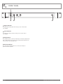
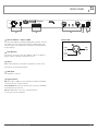
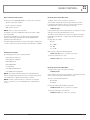
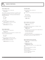
INSTALLATION AND OPERATION MANUAL
AMD SERIES
POWER AMPLIFIER
AMD2200P
IMPORTANT SAFETY INFORMATION
PRÉCAUTIONS DURANT UTILISATION
1. Read these instructions.
1. LISEZ ces instructions.
2. Keep these instructions.
2. Tenez ces instructions.
3. Heed all warnings.
3. Notez tous les avertissements.
4. Follow all instructions.
4. Suivez toutes les avertissements.
5. Do not use this apparatus near water.
5. N’utilisez pas ce produit près de l’eau (la piscine, la plage, le lac, etc.).
6. Clean only with dry cloth.
6. Nettoyez seulement avec une étoffe sèche.
7. Do not block any ventilation openings. Install in accordance with the
manufacturer’s instructions.
7. Ne bloquez aucuns troux de ventilation. Installez en accord avec
les instructions du manufacturier.
8. Do not install near any heat sources such as radiators, heat registers,
stoves, or other apparatus (including amplifiers) that produce heat.
8. N’installez près aucunes sources de chaleur comme radiateurs, registres
de chaleur, fours ou les autres équipements (y compris amplificateurs)
qui produisent la chaleur.
9. Do not defeat the safety purpose of the polarized or grounding-type plug.
A polarized plug has two blades with one wider than the other.
A grounding type plug has two blades and a third grounding prong.
The wide blade or the third prong are provided for your safety. If the
provided plug does not fit into your outlet, consult an electrician for
replacement of the obsolete outlet.
10. Protect the power cord from being walked on or pinched particularly
at plugs, convenience receptacles, and the point where they exit from
the apparatus.
11. Only use attachments/accessories specified by the manufacturer.
12. Use only with the cart, stand, tripod, bracket, or table specified by the
manufacturer, or sold with the apparatus. When a cart is used, use caution
when moving the cart/apparatus combination to avoid injury from tip-over.
13. Unplug this apparatus during lightning storms or when
unused for long periods of time.
14. Refer all servicing to qualified service personnel.
Servicing is required when the apparatus has been
damaged in any way, such as power-supply cord or plug
is damaged, liquid has been spilled or objects have fallen into the
apparatus, the apparatus has been exposed to rain or moisture, does
not operate normally, or has been dropped.
15. This appliance shall not be exposed to dripping or splashing water and
that no object filled with liquid such as vases shall be placed on the
apparatus.
16. Connect the equipment to an appropriate wall outlet that is readily
accessible.
17. The mains plug is used as the disconnect device and shall remain
readily accessible. If the mains plug is not readily accessible due to
mounting in a 19” rack, then the mains plug for the entire rack must
be readily accessible.
18. WARNING: To reduce the risk of fire or electric shock, do not expose this
apparatus to rain or moisture.
19. An appliance with a protective earth terminal should be connected to a
mains outlet with a protective earth connection.
9. Ne défaites pas le but de sécurité de la fiche polarisée ou base-type.
Une fiche polarisée a deux tranchants avec un plus large que l’autre.
Une fiche de base type a deux a deux tranchants et une troisième
pointe de base, le tranchant large ou la troisième pointe est fourni
pour votre sécurité. Si la fiche donnée ne conforme pas votre prise
de contact, consultez un électricien pour remplacement de la prise
de contact obsolète.
10. Protegez le cordon de secteur contre être marchée dessus ou pincez
en particulier aux fiches, aux douilles de convenance, et au point où ils
sortent de l’appareil.
11. Seulement utilisez attachements/accessoires spécifiés par le
manufacturier.
12. Utilisez seulement avec un chariot, un stand, un trépied, un support
ou une table indiquée par le manufacturier, ou vendue avec l’appareil.
Quand un chariot est utilisé, faites attention en déplaçant la combinaison
d’appareil/chariot pour éviter de se déséquilibrer.
13. Arrachez la fiche du dispositif durant éclair et orage ou
quand pas utilisé pour longues périodes de temps.
14. Référez au personnel qualifié de service pour toutes
réparations. La réparation est donnée quand le système
a été endommagé à n’importe façon, par exemple un fil ou une fiche
endommagé(e) de la source d’alimentation. Avoir été exposé à pluie ou
humidité, n’opère pas normalement, ou avoir été tombé.
15. L’appareil ne doit pas être exposé aux écoulements ou aux éclaboussures
et aucun objet ne contenant de liquide, tel qu’un vase, ne doit être placé
sur l’objet.
16. Branchez l’appareil à une source appropriée et faire que la prise à
débrancher soit facilement accessible.
17. La prise du secteur ne doit pas être obstruée ou doit être facilement
accessible pendant son utilisation. Pour être complètement déconnecté
de l’alimentation d’entrée, la prise doit être débranchée du secteur.
18. AVERTISSEMENT: Pour éviter le risque d’incendie ou de chocs électriques,
ne pas exposer cet appareil à la pluie ou à l’humidité.
19. Un appareil avec la borne de terre de protection doit être connecté au
secteur avec la connexiion de terre de protection.
PAGE 2
AMD2200P INSTALLATION AND OPERATION MANUAL
INTRODUCTION AND CONTENTS
AMD2200P
INTRODUCTION3
The AMD P series of power amplifiers from Australian Monitor
represent a quantum leap forward in connectivity, controllability &
flexibility in the constant voltage amplifier market. The AMD series
allows a contractor to integrate the power amplifier to a third
party control system for remote audio control or simply use the
AMD amplifiers as standard power amplifiers.
Australian Monitor AMD P series is the future of constant
voltage amplification.
FRONT PANEL
4
REAR PANEL
5
INSTALLATION6
RS232 PROTOCOL
7–8
COMMAND SUMMARY
9
DIMENSIONS10
SPECIFICATIONS11
Revision 1.0 May 2011
WARNING!
TO PREVENT FIRE OR SHOCK HAZARD, DO NOT USE THE PLUG WITH
AN EXTENSION CORD, RECEPTACLE OR OTHER OUTLET UNLESS THE BLADES
CAN BE FULLY INSERTED TO PREVENT BLADE EXPOSURE.
TO REDUCE THE RISK OF FIRE OR ELECTRIC SHOCK, DO NOT EXPOSE
THIS APPLIANCE TO RAIN OR MOISTURE.
TO PREVENT ELECTRICAL SHOCK, MATCH WIDE BLADE PLUG TO WIDE SLOT, FULLY INSERT.
CAUTION
RISK OF ELECTRIC SHOCK
DO NOT OPEN
The lightning flash with arrowhead symbol,
within an equilateral triangle, is intended
to alert the user to the presence of
uninsulated “dangerous voltage” within
the product’s enclosure that may be of
sufficient magnitude to constitute a risk
of electric shock to persons.
WARNING: TO REDUCE THE RISK
OF ELECTRIC SHOCK, DO NOT
REMOVE COVER (OR BACK).
NO USER SERVICEABLE PARTS INSIDE.
REFER SERVICING TO QUALIFIED
SERVICE PERSONNEL.
The exclamation point within an equilateral
triangle is intended to alert the user to
the presence of important operating and
maintenance (servicing) instructions in the
literature accompanying the appliance.
Rating plate and caution marking are marked on the back enclosure of the apparatus
AMD2200P INSTALLATION AND OPERATION MANUAL
PAGE 3
FRONT PANEL
1
2
3
4
1 Signal Indicator
The signal indicator will go blue when audio is present on that channel
of the amplifier.
2 Fault Indicator
The fault indicator will go red when a fault is present on that channel
of the amplifer.
3 Clip Indicator
The clip indicator will go red when an audio input is reaching the clipping stage.
If this is happening the input should reduced using the input attenuator at the
rear of the unit, or at the program source.
4 Control Indicator
The control indicator will flash whenever a control system adjusts a
parameter inside the amplifier.
PAGE 4
AMD2200P INSTALLATION AND OPERATION MANUAL
REAR PANEL
1
2
1 230 to 240V or 115V to 120V
The power input is NOT auto-switching. Australian Monitor should be contacted
if the voltage needs to be changed from its shipped configuration. The power
input also features a power switch, this is a hard power off and will shut down
the unit completely.
2 Amp Outputs:
The output for each channel can be either 100V Line, 70V Line or 4 Ohm low
impedence. Only one output type should be used at once.
3
4
5
Female XLR
PIN 2
HOT
(+)
PIN 1
GND
PIN 3
COLD
(–)
3 Inputs
Balanced line-level inputs on 3-pin XLR. Pin 1 Ground, Pin 2 Hot, Pin 3 Cold.
Input level trim for attenuating input signals.
4 USB Input
The USB input is for future use.
5 Logic Controls
VCA: When a RC1 or 500K pot is connected between a VCA pin and the GND,
connected audio can be remotely controlled.
Low Power Mode: When the low power mode pin is connected to the GND pin
the unit will enter low power mode.
RS232: The AMD Power P series can be controlled via RS232.
See page page 7 for more information.
AMD2200P INSTALLATION AND OPERATION MANUAL
PAGE 5
INSTALLATION
Unpacking
Cooling
Every Australian Monitor product is tested and inspected before leaving our
factory and should arrive in perfect condition.
The AMD2200P amplifier utilises fan forced air cooling, with air flowing from
right to left (viewed from the front).
When opening the carton check for any noticeable damage to your Australian
Monitor product. Please notify your Australian Monitor reseller immediately
should any damage be discovered.
Ensure adequate ventilation and/or heat extraction is provided when rack
mounting the amplifier. Installations with multiple AMD P series amplifiers or
other heat generating equipment with in the same rack will benefit from full
rack cooling, using conventional ducted cool-air fed through the rack base.
Should you ever need to re-ship the amplifier, always use the original
packaging carton and materials.
Mounting
The AMD2200P amplifier is one rack units high (1U) and will fit a standard
EIA 19 rack. A rack rear support bracket is supplied and must be must be
installed when rack mounting the amplifier. The rear support bracket should
be installed to the rack (rear rails) prior to mounting the amplifier. Failure to
mount or support the amplifier correctly may lead to chassis damage which is
not covered by warranty.
Typically amplifiers may be stacked directly on top of each other with no
need for spacing between units, unless installed in high ambient temperature
environments were a single rack unit space between amplifiers will assist
cooling further.
PAGE 6
For smaller installations or were rack cooling is not possible, ensure the rack
provides free air flow above and below the rack. Also avoid the use of rear
doors on the equipment rack.
Please consider the thermal dissipation figures provided later in this manual
when installing your AMD2200P amplifier.
Grounding
In the interests of safety, ensure the amplifier is connected to a suitable
grounded mains outlet and NEVER disconnect the earth pin on the
AC power cord.
AMD2200P INSTALLATION AND OPERATION MANUAL
RS232 PROTOCOL
Port & Protocol Information
Channel Input Cross Mix Level:
The RS232 port of the AMD2200P amplifier’s consists of three connections:
To adjust the volume control of an input cross mix level.
Transmit – Data from the amplifier
Receive – Data into the amplifier
GND – Ground connection
NOTE: there are no flow control connections
The baud rate of the port is 19200 and the data format is 8 bits, no parity
and 1 stop bit (8N1).
The protocol is an ASCII protocol – all characters in the string are ASCII
characters. A binary value spanning between hexadecimal 00 and FF is
transmitted as two ASCII characters.
All command strings start with the % character and end with a carriage return
– shown as <CR> in this document and equal to the ASCII value of 13 (0x0D)
Available Parameters
The following parameters can be externally controlled:
Channel Input Cross Mix Level
Channel Input Cross Mix Mute
*The Cross Mix commands allow any of the input channels to be mixed
to a particular output channel. In effect the 2-channel versions provide a
2x2 matrix and the 4 channel versions provide a 4x4 matrix.
%PCML:xyzz<CR>
In this command x represents the output channel to select (between 1 and 4)
and y represents the input channel (between 1 and 4).
The volume is represented by the zz section of the command. zz can range
between 00 (off) and E1 (225 = +12dB of gain). This allows half dB steps
throughout
the range where for example:
00 = Off
01 = -100dB
C9 = 0dB
E1 = +12dB
When a volume is adjusted the unit will reply with:
%PCML=xyzz<CR> where x, y and zz are as per above.
To request the current level of a source:
%PVAL:xy??<CR> where x and y are as per above.
Channel Output Level
Channel Output Mute
Low Power Mode
Channel Input Cross Mix Mute
Power Amplifier Fault Indication
To toggle the mute control of an input cross mix mute.
Power Amplifier Version Information
%PCMM:xyzz<CR>
NOTE: the Cross Mix commands allow any of the input channels to be
mixed to a particular output channel. In effect the 2-channel versions provide
a 2x2 matrix and the 4 channel versions provide a 4x4 matrix.
In this command x represents the output channel to select (between 1 and 4)
and the y represents the input channel (between 1 and 4)
NOTE: that in the 2 channel versions, if a command is accessed with
reference to channel 3 or 4, the command will be processed but will have
no effect.
00 = Unmuted
01 = Muted
The value of zz should either be 00 or 01.
If a mute flag is adjusted the unit will responded with:
%PCMM=xyzz<CR> where x, y and zz are as per above.
To request the current value of the mute flag:
AMD2200P INSTALLATION AND OPERATION MANUAL
%PCMM:xy??<CR> where x and y are as per above.
PAGE 7
RS232 PROTOCOL
Channel Output Level:
Low Power Mode
To adjust the volume control of an output channel.
To place the enable or disable “low power mode”
%PLVL:xyy<CR>
In this command x represents the output channel to select (between 1 and 4).
The volume is represented by the yy section of the command. yy can range
between 00 (off) and E1 (225 = +12dB of gain). This allows half dB steps
throughout the range where:
00 = Off
01 = -100dB
C9 = 0dB
E1 = +12dB
%PGRN:xx<CR>
In this command the xx represents whether the unit is in low power mode of
not.
00 = Normal Mode
01 = Low Power Mode
To request the current value:
%PGRN=??<CR>
When a volume is adjusted the unit will reply with:
%PLVL=xyy<CR> where x and yy are as per above.
To request the current level of a source:
%PLVL:x??<CR> where x is per above.
Power Amplifier Fault Indication
To poll the unit for its current fault status
%PAMP:x??<CR>
In this command x represents the channel to select (between 1 and 4).
The AMDXY00P will respond with.
%PAMP:xyy<CR>
Channel Output Mute
To toggle the mute control of an output channel.
%PMUT:xyy<CR>
In this command x represents the output channel to select (between 1 and 4).
The value of yy should either be 00 or 01.
00 = Unmuted
01 = Muted
In this command the yy represents whether the unit is in amplifier fault mode
00 = Amp is running in normal mode
01 = Amp is in thermal shutdown
02 = Amp is in fault shutdown
The PAMP command is a polled command, the AMD100/200 will not send
data regarding the amp status unless explicitly requested to do so.
If a mute flag is adjusted the unit will responded with:
%PMUT=xyy<CR> where x and yy are as per above.
To request the current value of the mute flag:
%PMUT:x??<CR> where x is as per above.
Power Amplifier Version Information
To poll the unit for its device and firmware information.
%PVER:??<CR>
The AMDXY00P will respond with.
%PVER:xy00P,aabbcccc<CR>
In this command xy can be either 21, 22, 41 or 42 to indicate the device
model.
aa represents the major firmware version number
(can range from 00 to FF)
bb represents the minor firmware version number
(can range from 00 to FF)
cccc represents the firmware revision number
(can range from 0000 to FFFF)
PAGE 8
AMD2200P INSTALLATION AND OPERATION MANUAL
COMMAND SUMMARY
Description CommandResponseNotes
Get input cross-mix level
%PCML:xy??<CR>
%PCML=xyzz<CR>
x ranges from 01 to 04
y ranges from 01 to 04
zz ranges from 00 to E1
Get input cross-mix mute
%PCMM:xy??<CR>
%PCMM=xyzz<CR>
x ranges from 01 to 04
y ranges from 01 to 04
zz ranges from 00 to 01
Set input cross-mix level
%PCML:xyzz<CR>
%PCML=xyzz<CR>
x ranges from 01 to 04
y ranges from 01 to 04
zz ranges from 00 to E1
Set input cross-mix mute
%PCMM:xyzz<CR>
%PCMM=xyzz<CR>
x ranges from 01 to 04
y ranges from 01 to 04
zz ranges from 00 to 01
Get output level
%PLVL:x??<CR>
%PLVL=xyy<CR>
x ranges from 01 to 04
yy ranges from 01 to E1
Get output mute
%PMUT:x??<CR>
%PMUT=xyy<CR>
x ranges from 01 to 04
yy ranges from 01 to 01
Set output level
%PLVL:xyy<CR>
%PLVL=xyy<CR>
x ranges from 01 to 04
yy ranges from 01 to E1
Set output mute
%PMUT:xyy<CR>
%PMUT=xyy<CR>
x ranges from 01 to 04
yy ranges from 01 to 01
Get green mode
x ranges from 00 to 01
%PGRN:??<CR>
%PGRN=xx<CR>
Set green mode
%PGRN:xx<CR>
%PGRN=yy<CR>
x ranges from 00 to 01
yy ranges from 00 to 01
Get version info
%PVER:??<CR>
%PVER=AMDxy00P, aabbcccc
xy is either 21,22,41 or 42
aa is the FW version major num
bb is the FW version minor num
cccc is the FW version revision
Get amp status
%PAMP:x??<CR>
%PAMP=xyy<CR>
x ranges from 01 to 04
yy ranges from 00 to 02
AMD2200P INSTALLATION AND OPERATION MANUAL
PAGE 9
482.00 mm (19.0”)
465.00 mm (18.3”)
44.00 mm
(1.75”)
32.00 mm
(1.25”)
DIMENSIONS
430.00 mm (16.9”)
438.00 mm (17.25”)
PAGE 10
AMD2200P INSTALLATION AND OPERATION MANUAL
SPECIFICATIONS
Frequency Response
Total Harmonic Distortion
Input Impedance
SpecificationConditions
70 Hz - 18 kHz, -3 dB Signal Input 2 dB below clip
< 0.6 %
Signal input 2 dB below clip
11 k ohms
Max Input
21 dBu
0 dBu
Gain pots adjusted accordingly
Gain pots at maximum
Crosstalk
> 70dB
1 kHz, maximum output
S/N Ratio
> 92 dB A-weighted, 20 Hz to 20 kHz
Power Output
4 ohm 70 V 100 V 200 W 200 W
200 W
28 Vrms
25 ohms
50 ohms
Power Consumption
Green Idle 1/8 power
1/3 power
12 W 20 W 92 W 204 W No USB or serial attached, 4 Ohm load
No USB or serial attached, 4 Ohm load
No USB or serial attached, 4 Ohm load
No USB or serial attached, 4 Ohm load
Thermal Dissipation
Green 12W (40.94 BTu/Hr
Idle 20W (68.24 BTu/Hr)
1/8 power 42W (143.30 BTu/Hr) Power Source Recommended Operating Temp Recommended Operating Humidity Dimensions (w x d x h) AC Mains (115-120 V 60Hz / 230-240 V 50Hz) 5 % to 95 %
430 mm x 438 mm x 44 mm
(16.9” x 17.25” x 1.75”)
11.5 kg (25.3 lbs)
Shipping Weight 13.5 kg (29.7 lbs)
AMD2200P INSTALLATION AND OPERATION MANUAL
Factory Configured
10° C to 45° C (50° F to 113° F)
Net Weight
Shipping Dimensions (w x d x h) Pink noise 12 dB crest factor, typical of
program music just before clip
Not including rack ears or rear panel connectors
540 mm x 530 mm x 140 mm
(21.3” x 20.9” x 5.5”)
PAGE 11
ENGINEERED BY AUSTRALIAN MONITOR
Address: 1 Clyde Street, Silverwater, Sydney NSW 2128 Australia. Private Bag 149, Silverwater NSW 1811 ABN 78 001 345 482
Website: www.australianmonitor.com.au International enquiries email: [email protected]
DISTRIBUTED IN AUSTRALIA AND NEW ZEALAND BY HILLS SVL www.hillssvl.com.au
NSW P: 02 9647 1411
E: [email protected]
QLD
ACT
P: 07 3852 1312
P: 02 6260 4544
E: [email protected] E: [email protected]
WA
P: 08 9204 0200
E: [email protected]
VIC
P: 03 9890 7477
E: [email protected]
SA
NZ
P: 08 8408 8300
P: 09 415 9426
E: [email protected] E: [email protected]