1
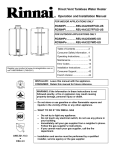
37AHB SERIES
HYDRONIC FURNACE
SIZES 045 THRU 090
Installation, Operation, and Maintenance Manual
Consumer Safety Information ................................ 2
Overview of the Rinnai Hydronic Furnace ............ 3
Model Number Nomenclature ................................ 3
Physical Data ......................................................... 4
Receiving & Checking Equipment ......................... 5
Installation
Clearances ..................................................... 5
Locating and Mounting ............................... 6-9
Plumbing ................................................. 10-13
Electrical Connections ............................ 14-16
Dip Switch Options....................................... 17
Thermostat Installation............................ 17-18
Start-Up Procedure ...................................... 19
Troubleshooting ...................................... 20-23
Sequence of Operation ................................... 24-26
Maintenance................................................... 26, 27
Selection Guide .............................................. 27, 28
Air Distribution Guide ..................................... 28, 29
Quick Reference Duct Sizing Chart .................... 30
Hydronic Furnace’s Specifications ....................... 31
Air Delivery and Performance Data ................ 32-51
Accessories .......................................................... 59
Wiring Diagrams ............................................. 60-62
Parts List ......................................................... 63-64
Limited Warranty ............................................. 65-66
To register your hydronic furnace or tankless water heater,
please visit www.rinnairegistration.com.
Quality Assurance
This product is manufactured in a
facility registered by UL to ISO 9001.
2100-536 Rev A
Consumer Safety Information
SAFETY DEFINITIONS
Indicates safety alerts. When this symbol is seen on the Hydronic Furnace and in all instructions and/or
manuals, be alert to the potential for personal injury. Recognize signal words DANGER, WARNING,
and CAUTION. These words are used with the safety alert symbol.
DANGER
Indicates an imminently hazardous situation which, if not avoided, will result in death or
serious injury.
WARNING
Indicates a potentially hazardous situation which, if not avoided, could result in death or
serious injury.
CAUTION
Indicates a potentially hazardous situation which, if not avoided, could result in minor or
moderate injury. It may also be used to alert against unsafe practices.
NOTICE
This is used to highlight important information which will aid in installation, improve
reliability or enhance operation.
SAFETY CONSIDERATIONS
Before any work is undertaken, it is imperative to
observe all precautions as stated in this manual, on
tags, and/or labels, together with any other safety
measures that may apply.
• Wear safety glasses and work gloves.
• When practical, objects to be brazed shall be
moved to a designated safe location or, if the
objects to be brazed cannot be readily moved, all
movable fire hazards in the vicinity shall be taken
to a safe place, or otherwise protected.
• Use quenching cloth for all brazing and un-brazing
operations.
• Suitable fire extinguishing equipment shall be
immediately available in the work area and shall
be maintained in a state of readiness for instant
use.
Read these installation instructions carefully and
adhere to all WARNINGS and CAUTIONS. Consult
local building codes, Occupational Safety & Health
Administration (OSHA) and National Electrical Code
(NEC) for special requirements.
WARNING
Before installing or servicing the Hydronic Furnace,
always turn off all power to unit. There may be more
than 1 disconnect switch. Electrical shock can cause
personal injury or death.
CAUTION
Failure to follow this caution may result in personal
injury. Sheet metal parts may have sharp edges or
burrs. Use care and wear appropriate protective
clothing.
NOTICE
Application of this Hydronic Furnace should be
indoors. Special attention should be given to unit
sizing and piping, filling, and purging.
Improper installation, modification, service,
maintenance, or use of Hydronic systems can cause
electrical shock, burns or other conditions which may
cause personal injury or property damage. Consult a
qualified installer, service agency, or your distributor
for information or support. The qualified installer or
agent must use factory authorized kits and/or
accessories when installing this product. Refer to the
appropriate Rinnai® literature for listing.
Read the entire instruction manual before starting the installation.
2
Rinnai Corporation Hydronic Furnace (37AHB) Manual
Overview of the Rinnai Hydronic Furnace (RHF)
INTRODUCTION:
The optimum in hydronic technology: the updated
Rinnai® multi-position Hydronic Furnaces offer a
unique solution for a wide variety of small and medium
sized residential and light commercial applications.
They are compact and ready to fit in tight spaces
which may include, but not limited to, attics,
basements, closets, crawlspaces, and utility rooms.
The 37AHB units are equipped with an intelligent
microprocessor control that allows for domestic hot
water priority and adapts to available hot water flow for
space heating by automatically regulating the pump
and blower sequence to maximize comfort.
These unique Hydronic Furnaces are designed to
work in combination with our line of Rinnai® tankless
products to deliver a wide variety of heating capacities
that cover the entire residential and light commercial
heating spectrum.
Because our units are designed specifically to the
Rinnai® tankless products, our stated capacities are
fine tuned and are based on the “Hydronic Furnace /
Tankless Water Heater” match set and NOT a given
water flow rate.
CODES AND STANDARDS:
It is the responsibility of the installer to follow all
national codes, standards and local ordinances, in
addition to instructions laid out in this manual. The
installation must comply with regulations of the local
building, heating, plumbing, and other codes. Where
local codes are not applicable, the installation must
comply with the national codes and any and all
authorities having jurisdiction.
The following is a suggested list of codes and
standards for the United States and Canada:
General Installation
Installation of Air Conditioning and Ventilating Systems
NFPA 91 (latest edition)
Duct Systems
Sheet Metal and Air Conditioning Contractors National
Association (SMACNA)
American Society of Heating, Refrigeration, and Air
Conditioning Engineers (ASHRAE)
2001 Fundamentals Handbook Chapter 34 or 2000
HVAC Systems and Equipment Handbook Chapters 9
and 16
US and CANADA: Air Conditioning Contractors
Association (ACCA) Manual D
Acoustical Lining and Fibrous Glass Duct
US and CANADA: current edition of SMACNA; NFPA
90B as tested by UL Standard 181 for Class I Rigid Air
Ducts
Electrical Connections
US: National Electrical Code (NEC) ANSI/NFPA 70
(latest edition)
CANADA: Canadian Electrical Code CSA C22.1
(latest edition)
Plumbing Systems:
US and CANADA: ICC International Plumbing Code
(IPC); Uniform Mechanical Code (UMC); Uniform
Plumbing Code (UPC)
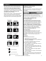
Model Number Nomenclature
37AH
B
045
08
K
A 5
Model
Multi-position
37AH - Multi-Speed Hydronic Furnace
5 = Yes
2 = No
Series
A - Unit with PSC Motor
B - Unit with ECM Technology
Engineering Digit
Nominal Heating
Capacity (BTU/h)
Cooling / Heating Air Flow Range (CFM)
045 = 45,000
060 = 60,000
075 = 75,000
090 = 90,000
08 = 800 (650-800)
12 = 1200 (650-1200)
14 = 1400 (1000-1600)
16 = 1600 (1200-1750)
Rinnai Corporation Hydronic Furnace (37AHB) Manual
Denotes minor change
(not present in sales or service
literature)
Voltage Code (V-Ph-HZ)
K = 115 - 1 - 60
L = 240 - 1 - 50 (export models)
3
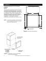
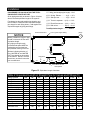
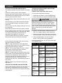
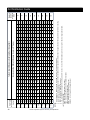
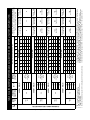
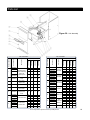
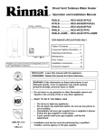
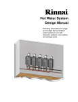
Table 1 - Physical Data
DIMENSIONS
A
UNIT SIZE
B
C
D
E
in.
mm
in.
mm
in.
mm
in.
mm
in.
mm
37AHB04508KA5
14
355.6
18
457.2
12
304.8
10 - 1/2
266.7
19
482.6
37AHB06012KA5
17 -1/2
444.5
18
457.2
16
406.4
16 - 11/16
423.9
19 - 1/4
489.0
37AHB07514KA5
21
533.4
18
457.2
20
508
18 - 11/16
474.7
19 - 1/2
495.3
37AHB09016KA5
24 - 1/2
622.3
18
457.2
24
609.6
21 - 1/8
536.6
19
482.6
C
B
1"
7/8” Dia. KO Thermostat Wire
Entry (Typ. for both sides)
34"
17 13/16"
Water Out
2 1/8"
17 13/16"
Water In
E
18 5/16"
1"
D
7/8” Dia. KO Supply
Power Wire Entry
(Typ. for both sides)
A
6"
1 3/8"
Figure 1
4
Rinnai Corporation Hydronic Furnace (37AHB) Manual
22"
Receiving and Checking Equipment
IDENTIFY UNIT
The unit model number and serial number are stamped
on the unit identification / name plate (located on the
top right side of unit). Check this information against
shipping papers and job requirements.
INSPECT SHIPMENT
Upon receipt of a 37 Series Hydronic Furnace the
packaging should be checked for peripheral signs of
transportation damage while unit is still in the shipping
package. If unit appears to be damaged or is torn
loose from its anchorage, the unit shall be immediately
examined by the receiving party before removal. If
damage is found, the receiving party must sign the
driver’s delivery receipt noting all damage (i.e. carton
damage and/or product damage) as well as contact the
last carrier immediately, preferably in writing,
requesting inspection by the carrier’s agent. All claim
papers MUST be forwarded to Rinnai® America
Corporation for processing. In general, upon receipt of
product, be sure to check all items against shipping list;
if items are found to be missing, it should be noted as
such on the driver’s delivery receipt; and the receiving
party shall also immediately notify the area
distributor. To prevent loss or damage, leave all parts
in original packages until installation.
Installation
The 37AHB Series Hydronic Furnace needs to be
installed and commissioned by a knowledgeable
qualified professional.
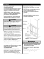
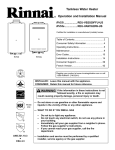
TOP/PLENUM
zero
NOTES:
BACK
zero
SIDE
zero
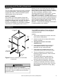
1. This Furnace is approved for up-flow, down-flow,
and horizontal configurations.
2. Clearance arrows do not change with Hydronic
Furnace orientation.
3. This Hydronic Furnace is for indoor
installation only.
FRONT
zero
SIDE
zero
SERVICING
24” (610 mm)
BOTTOM
zero
Figure 2: Minimum Clearance to Combustible
Construction
WARNING
4. Unit(s) shall be installed in such a way as to
ensure that the electrical components are
protected from any contact with water.
5. Unit(s) shall not be installed directly on any
combustible material other than wood flooring.
6. This unit is designed to be used with an air
distribution system (ductwork). Refer to section
the Air Distribution.
7. The installer shall provide ample space for
servicing and cleaning. Always comply with
minimum clearances as shown in Figure 2.
8. The 37AHB units are designed to be installed
vertically or horizontally on the floor; units may
also be hung from the ceiling or wall. Be sure to
allow appropriate clearances for wiring, piping,
and servicing.
Do not install this unit if the unit is damaged.
Do not install this unit if any part or all of unit has been
under water. Refer to the Receiving and Checking
Equipment section.
Rinnai Corporation Hydronic Furnace (37AHB) Manual
5
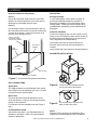
Installation
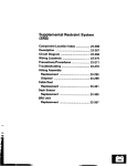
LOCATING AND MOUNTING THE HYDRONIC
FURNACE
General
The multi-position 37AHB Series Hydronic Furnaces
are shipped in packaged configuration. This means
that the units may be installed without assembly and/
or modifications when configured for bottom return air
inlet application; however, some modifications and
assembly are necessary if units are to be installed in
an application that requires side return air inlet
arrangement. For instructions on required
modifications and assembly refer to Figures 3 and 4.
NOTE: For side return application, obtain Side Filter
Rack” and “Bottom Fill Plate from your area
authorized Rinnai® distributor.
17 15/16"
17 3/4"
21 11/16"
1/8"
2 3/16"
3/8"
USE EXI STING SCREW HOLE
TO LOCATE FILTER RACK
Figure 4: Side Filter Rack Installation
Figure 3: Modification of Unit to Accommodate
Side Filter Rack Installation
6
Rinnai Corporation Hydronic Furnace (37AHB) Manual
Installation
Blower located below coil
section. Conditioned air is
discharged upward.
Blower located to the left of coil
section. Conditioned air is
discharged to the right.
Blower located to the right of
coil section. Conditioned air is
discharged to the left.
Blower located above coil
section. Conditioned air is
discharged downward.
Figure 5: Multi-Position Orientation
Upflow Installations
Downflow Installation
The 37AHB Hydronic Furnace is ready to install in the
up-flow position without modifications.
The 37AHB Hydronic Furnace is ready to install in the
down-flow position without assembly or modifications
when configured for bottom return air inlet installation.
If side return air inlet installation is desired refer to
Figures 3 and 4.
The unit MUST be supported on the bottom ONLY and
set on a field supplied supporting frame or plenum.
Supporting frame or plenum must be anchored to the
unit and to the floor or wall.
The 37AHB Furnaces are shipped without a bottom fill
plate. If side return installation is desired, the return
opening (Bottom) must be blanked off. If a bottom fill
plate is required, install only a factory authorized
bottom fill plate. Refer to the Rinnai Accessory list for
details. For side filter rack installation instructions
refer to Figures 3 and 4.
Horizontal Left and Right Installations
Without Cased Coil:
If a cased coil is NOT being installed, the cabinet can
be placed on either side for horizontal airflow as
shipped, when configured for bottom return air inlet
installation. If side return air inlet installation is desired
refer to Figures 3 and 4.
With Cased Coil (Field Supplied):
Refer to the manufacturer’s Cased Coil installation
instructions for details.
Rinnai Corporation Hydronic Furnace (37AHB) Manual
7
Installation
CLOSET INSTALLATION (RETURN AIR THRU
OPENING OR GRILL)
The 37AHB Hydronic Furnace can be installed in a
closet on a supporting stand or be mounted from the
closet wall using the closet as the return air plenum.
Unit should be high enough from the floor to provide
unimpeded return air flow into the bottom of the
cabinet.
Closet return air opening can be on the front (in closet
door), side (thru the wall) or a combination of both,
providing there is clearance on the sides between
unit’s cabinet and closet. Refer to ACCA Manual D or
SMACNA for sizing and free area recommendations.
NOTE: Local codes may limit application of systems
without a ducted return to single story dwellings.
IMPORTANT: When a 37AHB unit is matched with an
evaporative type (cased coil/condensing unit) split
system for cooling application and the system is
installed above a finished ceiling and/or an occupied
space, building codes may call for a secondary
insulated condensate pan (by others) to be installed
under the entire unit. In other instances, some local
codes may allow the running of a separate, secondary
condensate line in lieu of the required drain pan. It is
the responsibility of the installer to consult local codes
for compliance.
WARNING
It is the installer’s responsibility to use an appropriate
hanging method capable of supporting the unit’s
weight. Refer to the specification section of this
document for the respective unit’s installed weights.
SUSPENDED CABINET INSTALLATION
If the cabinet cannot be supported on a frame or
supported from the wall, it may be suspended.
Use metal strapping or threaded rod with angle iron
under cabinet for support. These supports MUST run
parallel with the length of the cabinet (see Figures 6
and 7).
NOTICE
For seismic hanging requirements, refer to local
codes.
Ensure that there is adequate room to remove service
and access panels after installing supporting brackets.
If an auxiliary drain pan is required, the support is to
be placed under the drain pan. In such installations
the unit will need to be supported on vibration isolators
(rubber or Styrofoam blocks).
1/4” THREADED ROD
(4 REQUIRED)
DOOR
ASSEMBLY
8” MIN FOR
DOOR REMOVAL
(2) HEX NUTS, (2) WASHERS & (2)
LOCK WASHERS REQ. PER ROD
SECURE ANGLE
IRON TO BOTTOM
OF CABINET WITH 3
#8 x 3/4” SCREWS
TYPCIAL FOR 2
SUPPORTS
USE 1” SQUARE, 1-1/4 x 1-1/4 x 1/4
ANGLE IRON OR EQUIVALENT
Figure 6: Horizontal Unit Suspension
8
Rinnai Corporation Hydronic Furnace (37AHB) Manual
Installation
Attachment Methods Using Straps
AIR SYSTEM
Method 1
Existing Ductwork
Use (4) #8 x 3/4 sheet metal screws for each strap.
Straps to be vertical against the unit’s sides and not
allowed to be pulled away from the sides.
It is the responsibility of the installer to inspect all
previously installed air distribution systems to
determine its suitability for the new heating and/or
cooling system. Existing ductwork may have to be
modified and/or insulated to provide satisfactory air
distribution.
Method 2
Fold all straps under the furnace and secure with (4)
#8 x 3/4 sheet metal screws (2 screws at the side and
2 screws at the bottom. (Care must be taken not to
drive the screw through the coil.)
1 INCH x 22 GAUGE
GALVANIZED STRAPS
TYPICAL FOR 4 STRAPS
RETURN AIR
OPENING
DOOR
ASSEMBLY
Ductwork Installation
Connect the supply-air duct over the outside of 3/4-in.
flange on the unit’s discharge side. Secure the duct to
the flange with proper fasteners for the type of duct
used. Support the duct independently.
Use flexible connectors (if desired between the
ductwork and the unit to prevent transmission of
vibration.
Use insulation with vapor barrier for ductwork passing
PROHIBITED INSTALLATIONS
Back
COIL
INTERFACE
AREA
BACK OF UNIT
Front
SUPPLY AIR OPENING
Figure 7: Horizontal Unit Suspension with Straps
DUCT CONNECTIONS
Figure 8: The air inlet is not allowed to be at
Supply Duct
The supply ductwork must be attached to the outside
of the flange on the air discharge end of unit. Flexible
connectors may be used if desired.
the front or back of the furnace
Return Duct
The return ductwork should be attached to the air
return side (bottom or side) of unit using sheet metal
screws or other fasteners.
For side return air inlet installation see the Figures 3
and 4.
FILTER INSTALLATION
Internal filter rack and a 1 inch disposable filter are
standard on all models. Refer to the Specifications
section for dimensions.
Figure 9: Do not position the furnace on its
back or with it face down.
NOTE:
Multiple Furnace configured for installation with a
single Rinnai Tankless Water Heater is prohibited.
Rinnai Corporation Hydronic Furnace (37AHB) Manual
9
Installation
PLUMBING
Mechanical Joining of Tubing:
Codes:
Where used, refer to the respective mechanical
system manufacturer’s installation instructions.
Observe all local sanitary codes when installing water
lines. The water supply mating connection to the
37AHB Hydronic Air-Handling Units are made via the
two (3/4 in. Dia. X 2-1/2 in. Long) copper stubs to the
front-left of the unit labeled “WATER IN” and “WATER
OUT” (see Figure 1). Mating connectors to be two
field supplied 3/4 in. FNPT-sweat ends or two fieldsupplied 3/4 in. SharkBite type FNPT-push fitting ends
or equivalent.
All associated hydronic piping MUST comply with ICC,
UPC and any other local codes or ordinances having
jurisdiction. USE POTABLE GRADE COPPER OR
OTHER PIPING MATERIALS. MATERIALS TO BE
LEAD FREE APPURTENANCES ONLY.
Tubing Insulation:
Any tube conveying fluid at a temperature greater than
that of the surrounding air releases heat.
Insulate all accessible hot water lines and associated
valves with material, such as expanded neoprene or
polyurethane 3/8-in. to 1⁄2-in. thick.
Match the pipe sleeve's inside diameter to the pipe’s
outside diameter for a snug fit. Place the pipe sleeve
so the seam will be face down on the pipe. Tape,
wire, or clamp insulation every foot or two to secure it
to the pipe. If taping is desired, use acrylic tape
instead of duct tape.
NOTE: Recommended piping, fittings, valves and
other appurtenances (exclusive of those indicted as
accessories that are available through Rinnai
distribution) called for in piping schematics to be fieldsupplied.
Copper Tubing Support:
Flow Sensor Installation:
(Required for Open Loop Systems)
•
1/2 in. to 3/4 in. tube: 5 feet maximum spacing
Care must be taken to ensure that the flow sensor is
not damaged due to excessive tightening. The torque
must not exceed the maximum limit stated below. The
installation should be checked to ensure that no
leaking is evident.
•
1 in. to 1-1/4 in. tube: 6 feet maximum spacing
•
1-1/2 in. to 2 in. tube: 8 feet maximum spacing
Mating connectors to be (2) 3/4” FNPT fittings (field
supplied).
Pipe-work/connector alignment is imperative (avoid
bending stress).
Polytetrafluoroethylene (PTFE) thread seal tape (teflon
tape), or equivalent, is recommended.
Tighten fittings to maximum torque of 15lb/ft (20Nm).
Soldering Copper Tubing:
The common method of joining copper tubing in
hydronic heating systems is soft soldering. Plumbing
codes do not allow solders containing lead to be used
for domestic water service. USE ONLY 95/5 tin/
antimony solder for all piping systems that incorporate
a domestic water supply.
Note: Precautions must be taken during soldering to
avoid debris or solder from lodging in piping
system.
10
Copper tubing must be properly supported to prevent
sagging or buckling. On horizontal runs with hard
temper tubing, the following maximum support spacing
is suggested:
The above suggested spacing does not account for
extra weight of piping components such as an
expansion tank, etc. When such components are
present the piping should be supported immediately
adjacent to the component.
On vertical runs, copper tubing should be supported at
each floor level or at a maximum of every 10 feet.
Thermal Expansion of Piping:
In all hydronic systems, piping undergoes temperature
swings as the system operates. This causes changes
in the length of the piping due to thermal expansion.
If the piping is rigidly mounted, this expansion can
cause annoying popping or squeaking sounds and in
extreme cases, the piping can even buckle.
To counter expansion movement, design piping
circuits with sufficient elbows, tees or expansion loops
(only used in large systems) or piping supports that
allow the tubing to expand and contract freely.
Another alternative is to install an expansion
compensator fitting capable of absorbing the
movement.
Rinnai Corporation Hydronic Furnace (37AHB) Manual
Installation
Hydraulic Resistance of Fittings, Valves, and Other
Devices:
Before the total hydraulic resistance of a piping circuit
can be found, the individual hydraulic resistances of all
fittings, valves, or other such components must be
determined. One approach is to consider each fitting,
valve, or other device as an equivalent length of
copper tube of the same pipe size (see Table 2).
By using the equivalent length of piping for all
components in the circuit, the circuit can be treated as
if it were a single piece of pipe having a length equal
to the sum of the actual pipe length, the total
equivalent lengths of all fittings, valves, or other
devices. Refer to Figure 10 and the associated
computation of equivalent lengths.
Pipe Sizing Considerations:
When selecting a pipe size for a given flow rate, the
resulting average flow velocity should be between 2
and 4 feet per second.
At water flow velocities of approximately 2 feet per
second, flowing water will carry air bubbles along a
vertical pipe. Average flow velocities of 2 feet per
second or higher can draw along air bubbles in a
downward flow. At the above stated velocities air
bubbles shall be routed to an air separator where they
can be collected and discharged from the system.
Use Taco 4900 series air separator, Model 49-075, or
equivalent (field supplied).
Average flow velocities higher than 4 feet per second
could cause flow noise and should be avoided.
Expansion Tanks:
All liquids used in hydronic heating systems expand
when heated. For all practical purposes, liquids are
incompressible. Any container completely filled with a
liquid and sealed from the atmosphere will experience
a rapid increase in pressure as the liquid is heated.
To prevent this from occurring, all modern hydronic
systems MUST be equipped with an expansion tank.
Refer to expansion tank manufacture’s instructions for
proper sizing and installation.
Rinnai Corporation Hydronic Furnace (37AHB) Manual
11
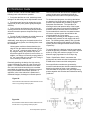
Installation
¾” Tubing (total straight pipe length)....68 ft.
PROCEDURE FOR CALCULATING THE TOTAL
EQUIVALENT LENGTH OF PIPE
(6) ¾” 90 deg. Elbows….……..6(2) = 12 ft.
Given piping assembly as shown in Figure 10 below,
what is the total equivalent length of the system?
(2) ¾” Side port tee……….…..2(3) = 6.0 ft.
(1) ¾” Taco air separator….1(0.3) = 0.3 ft.
First determine the total straight pipe lengths; next
refer to table 2 to determine the equivalent straight
pipe length for each fitting shown. Add together the
equivalent lengths of piping and fittings.
(1) ¾” Rinnai flow sensor.....1(3.2) = 3.2 ft.
(2) ¾” Ball valves….….….....2(2.2) = 4.4 ft.
Total Equivalent length……..……93.9 ft.
3/4 in. type M copper tubing
Rinnai Flow Sensor
NOTICE
FS
Where possible the length of pipe
should not exceed 150 feet total
equivalent length.
Any piping running through
unconditioned space MUST be
insulated to prevent heat loss,
and possible freezing of the line.
gauge
9 ft
4 ft
15 ft
3 ft
10 ft
5 ft
12 ft
Stickers indicating direction of
flow, (WATER IN, and WATER
OUT) are labeled on the outside
of the cabinet. DO NOT reverse
these lines, as this will cause the
unit to malfunction.
10 ft
ball valves
3 ft
3 ft
3 ft
3 ft
3 ft
cap
TACO Model 49-075
Air Separator
Figure 10 Equivalent Length Calculation
Table 2: Equivalent Length of Straight Pipe for Valves and Fittings (ft)
Fitting or Valve
90 deg. Elbow
45 deg. elbow
Straight thru tee
Side port tee
Reducer coupling
Gate valve
Globe valve
Angle valve
Ball valve
Swing check valve
Flow check valve
Butterfly valve
Rinnai Flow Sensor
3/8"
0.5
0.35
0.2
2.5
0.2
0.35
8.5
1.8
1.8
0.95
NA
NA
NA
1/2"
1
0.5
0.3
2
0.4
0.2
15
3.1
1.9
2
NA
1.1
NA
3/4"
2
0.75
0.4
3
0.5
0.25
20
4.7
2.2
3
83
2
3.2
1"
2.5
1
0.45
4.5
0.6
0.3
25
5.3
4.3
4.5
54
2.7
NA
1 1/4"
3
1.2
0.6
5.5
0.8
0.4
36
7.8
7
5.5
74
2
NA
1 1/2"
4
1.5
0.8
7
1
0.5
46
9.4
6.6
6.5
57
2.7
NA
2"
5.5
2
1
9
1.3
0.7
56
12.5
14
9
177
4.5
NA
2 1/2"
7
2.5
0.5
12
1
1
104
23
0.5
11
85
10
NA
3"
9
3.5
1
15
1.5
1.5
130
29
1
13
98
15.5
NA
Taco 49-075 Air
NA
NA
0.3
NA
NA
NA
NA
NA
NA
12
Rinnai Corporation Hydronic Furnace (37AHB) Manual
Installation
Piping Configuration
air bubbles.
When employing a Tankless Water Heater in a
combination hydronic hot water heating system, the
system is considered an Open Loop System; i.e. the
system must be configured to simultaneously deliver
both domestic hot water and space heating. By
definition, if the circuit is sealed off from the
atmosphere at all locations (as is true for most modern
hydronic systems) it is called a closed loop system.
Conversely If the circuit is open to the atmosphere at
any point, it is called an open loop system. Current
Rinnai tankless products are not certified for closed
loop applications. Furnaces may be used in closed
loop application only with the new Rinnai Condensing
Boilers. Refer to Boiler Manuals for more details.
STEP 1: CLOSE the air separator venting valve.
Open Loop System
If piping is done in accordance with the recommended
schematic diagram shown in Figure 11, the following
purge and priming procedure applies.
PURGING AND PRIMING THE SYSTEM:
The following procedure describes how the Rinnai®
system may be piped to eliminate the need for a
“purge cart” to fill the system and remove entrapped
STEP 2: CLOSE ball valve 3 (BV3);
STEP 3: OPEN drain valve 3 (DV3) to which a hose
MUST be connected and draining to a sink, drain or
outdoors.
STEP 4: CLOSE drain valves 1 & 2 (DV1 and DV 2)
and OPEN ball valve 2 (BV2).
STEP 5: OPEN cold water supply main valve (ball
valve 1 - BV1). The system will begin the prime/purge
process using the street pressure. Entrapped air
bubbles being pushed out of the system will be evident
by a slight vibration of the discharge hose connected
to drain valve 3 (DV3). The hose will stop vibrating
when laminar flow is achieved.
STEP 6: CLOSE drain valve 3 (DV3);
STEP 7: OPEN ball valve 3 (BV3). The system is now
purged, primed and ready to go.
STEP 8: OPEN the air separator venting valve.
Note: For an open loop system, use expansion tank
approved for potable water use only.
(BV)
(DV)
All piping to be 3/4 inch.
Field Supplied Ducting
Field Supplied
Evaporator Coil
Figure 11 - Typical Piping Arrangement For Direct Space Heating and Domestic Water Supply with Tankless
Water Heater. Open Loop
Rinnai Corporation Hydronic Furnace (37AHB) Manual
13
Installation
ELECTRICAL CONNECTIONS
side) follow steps 1 thru 7 below:
Line-Voltage Connections:
1. Remove and keep one screw and cover from the
Control Box.
U.S. INSTALLATIONS: Make all electrical connections
in accordance with National Electrical Code (NEC)
ANSI/NFPA 70 and all local codes or ordinances
having jurisdiction.
CANADIAN INSTALLATIONS: Make all electrical
connections in accordance with Canadian Electrical
Code CSA C22.1 and all authorities having
jurisdiction.
Check all factory wiring per unit wiring diagram and
inspect factory wiring connections to be sure none
were loosened in transit.
2. Remove and keep two screws holding Control Box
to casing of 37AHB unit (See Fig. 12.).
3. Remove wire tie from looped wires attached to
Control Box.
4. Before Control Box is reinstalled, remove the
scored piece of insulation from the desired side.
Remove two knockouts in the casing where the
Control Box is to be installed.
WARNING
Before installing or servicing system, always turn off
all power to system. There may be more than 1
disconnect switch. Electrical shock can cause
personal injury or death.
CAUTION
If a disconnect switch is to be mounted on the unit,
select a location where a drill or fastener will not be in
contact with electrical or hydronic components.
Electrical shock can cause personal injury or death.
NOTE: Prior to making any electrical connections,
ensure that supply voltage, frequency, and phase are
as specified on unit rating plate.
Check to ensure that the existing electrical service is
adequate to handle the additional load imposed by the
Hydronic Furnace. Refer to unit wiring diagram for
proper electrical connections.
All electrical connections MUST comply with NEC and
any other local codes or ordinances having
jurisdiction. USE COPPER WIRE ONLY. Provide
separate branch electric circuit with field supplied
disconnect switch.
Location of disconnect switch to be in clear site,
accessible and in close proximity to the unit.
Correct polarity MUST be maintained for 115 V wiring.
If polarity is incorrect unit will NOT operate.
Control Box Relocation:
The Control Box is factory installed in the blower
compartment upper left corner (see Figure 12); if
factory location of Control Box is suitable, proceed to
next section. To relocate the Control Box to an
alternate location (blower compartment upper right
14
Figure 12: Control Box Relocation
WARNING
Do NOT remove ground screw inside control box.
5. Secure Control Box to casing with the two screws
removed and kept from Step 2.
6. Reinstall two plastic plugs (from spare parts bag)
where indicated in openings on adjacent side of
Control Box.
7. Route Control Box wiring within unit away from hot
surfaces, sharp edges and rotating parts.
Rinnai Corporation Hydronic Furnace (37AHB) Manual
Installation
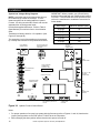
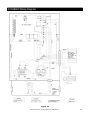
NOTES:
W
1. Connect Y1 terminal as
shown for proper operation.
R
C
Single Stage
Thermostat
(Available Accessory)
Y1
5 Wire
2. Rinnai thermostats require a
“C” terminal connection as
shown.
3. If any of the original wire, as
supplied, must be replaced,
use the same type or
equivalent wire.
G
Field 115, 208 / 230 Volt Wiring
3 Wire Heating Only
Field 24 Volt Wiring
Factory 24 Volt Wiring
HYDRONIC FURNACE
Junction Box
Factory 115 Volt Wiring
Y1
208 / 230 Volt
Single Phase
Y2
BLK
BLK
WHT
WHT
L1
W
PCB
G
L2
O
R
GND
Control Box
P3
115 Volt Fuse Disconnect
(Field Supplied)
C
24 Volt Terminal Block
Flow Sensor
(Packaged with Unit) FS
Condensing Unit
(Field Supplied)
GND
Disconnect
(Field Supplied)
24 Volt FS / WH Connector
Figure 13: Field Wiring Diagram
Electrical Connection to Control Box
1. Route the furnace power wires through aligned
holes in casing and Control Box and make field
wire connections in Control Box. Use best
practices for wire bushings, strain relief, etc.
Field wiring to the unit must be grounded and
conform to the National Electrical Code C22.1 Part
1 - latest edition. Use only UL listed conduit and
conduit connectors to connect supply wires to the
unit and provide appropriate grounding.
Grounding may also be accomplished by
grounding the control box per appropriate local
codes. Electric wires that are field installed shall
conform to the temperature limitation for 63° F
(35° C) rise when installed in accordance with
instructions. Refer to Table 4 for specific furnace
electrical data.
2. Route and secure field ground wire to ground
screw on Control Box.
3. Connect line voltage leads as shown in Figure 13.
4. Reinstall cover to Control Box. Ensure that wires
are not pinched between cover and edge of
Control Box.
WARNING
24V Control System Connections to Unit’s PrintedCircuit Board (PCB):
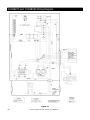
Refer to Figures 25 through 27 for factory wiring
details. For low voltage connections between the unit
and the thermostat, use No. 18 AWG color-coded,
insulated (63° F / 35°C minimum) wires. (Refer to
Figures 16 through 19.)
Low Voltage Connections:
These units use a grounded 24 volt AC low voltage
circuit and require at least a Single stage heating and
a Single stage cooling thermostat.
The “R” terminal is the hot terminal and the “C”
terminal is grounded.
“G” terminal is the fan input.
“Y1” terminal is the compressor Stage 1 input.
“Y2” terminal is the compressor Stage 2 input.
“O” terminal is the reversing valve input. The
reversing valve must be de-energized for heating
mode.
“R” terminal is 24 VAC hot.
“C” terminal is 24 VAC grounded.
“W” terminal is the heat input. This terminal also
energizes the emergency heat if configured for heat
pump.
Failure to follow this warning could result in a fire. Do
not use aluminum wire between the Hydronic Furnace
and the disconnect switch. USE COPPER WIRE
ONLY.
Rinnai Corporation Hydronic Furnace (37AHB) Manual
15
Installation
System Low Voltage Wiring Diagrams
NOTE: Local codes may require thermostat wiring to
be routed through conduit or raceways. In such
instances splices can be made inside the Hydronic
Furnace. All wiring must be NEC Class l and must be
separated from incoming power leads.
IMPORTANT: Where possible, use a Rinnai factory
authorized thermostat with the 37AHB series Hydronic
Furnaces. If a thermostat other than specified is used,
refer to the manufacturer’s installation instructions for
further details.
Provide field supplied disconnect. Refer to Table 4
(Specifications) for maximum fuse or circuit breaker
sizes.
Wire Gauge
Maximum Distance (feet)
20 gauge
45
18 gauge
60
16 gauge
100
14 gauge
160
12 gauge
250
Transformer is factory wired for 115v operation. (See
Figures 27 through 29.)
The secondary circuit of the transformer is protected
by a 3-amp fuse mounted on the printed-circuit board.
SW1 SET-UP SWITCH
AND HEATING BLOW
OFF DELAY
FLOW SENSOR
CONNECTIONS
115 VAC (L2)
NEUTRAL
CONNECTIONS
P3
P7
PUMP
CONNECTIONS
FLASH UPGRADE
CONNECTION
(FACTORY ONLY)
P4
u1
24 V THERMOSTAT
TERMINALS
115 VAC (L1) LINE
VOLTAGE
CONNECTION
AN1
STATUS LED LIGHT
OPERATING MODE
JUMPER (SHUNT)
FAN
PARK
TRANSFORMER 24 V
CONNECTIONS
FAN
CONNECTION
HEATING
P1
3 AMP FUSE
HUMIDIFIER CONNECTIONS
(DRY CONTACT) 24 VAC OR
115 VAC
FAN
CONNECTION
COOLING
Figure 14: Hydronic Furnace Control Board
Notes:
1. For proper operation of an open loop system with the flow sensor refer to Figures 11 and 14; Note that the
jumper (shunt) position on the PCB “point P7” MUST be in the FS position.
2. When changing the shunt position ensure that the unit’s power is turned off.
16
Rinnai Corporation Hydronic Furnace (37AHB) Manual
Installation
Dip Switch Options (Smart Operating System):
THERMOSTAT INSTALLATION:
The Rinnai® exclusive Smart Operating System is a
feature of your 37AHB series Hydronic Furnace’s
control system that is designed to allow the installer
(via DIP Switch – SW1) to configure the unit for single
or two stage, A/C or Heat pump systems with
selectable heat bower off delay.
Safety Considerations:
Refer to Figures 14 and 15 for the proper dip switch
setting to be used with the desired configuration.
When viewed with the Furnace in the upflow position,
the dip switch will be as shown below (upside down.
All wiring must conform to local and national electrical
codes. Improper wiring or installation may damage
thermostat.
WARNING
Before installing thermostat, turn off all power to unit.
There may be more than one power disconnect.
Electrical shock can cause personal injury or death.
INSTALLATION CONSIDERATIONS:
Air Conditioner Model:
2
3
4
O 1
N
2
3
4
SINGLE-STAGE HP
CONFIGURATION
TWO-STAGE A/C
CONFIGURATION
O 1
N
SINGLE-STAGE A/C
CONFIGURATION
(DEFAULT)
TWO-STAGE HP
CONFIGURATION
The Standard Model A/C thermostat may be wired
with or without connecting a common wire between
the indoor equipment and the thermostat. However, it
is recommended to use a common wire whenever
possible. Without a common wire this thermostat
becomes "power stealing." This means it will need to
steal a small amount of power from the equipment to
which it is connected. When "power stealing"
connection is used, the supplied 270 ohm resistor
must be connected at the indoor unit.
Heat Pump Model:
O 1
N
2
3
4
O 1
N
2
3
4
30 SECONDS OFF
DELAY (DEFAULT)
60 SECONDS OFF
DELAY
The Standard Model HP thermostat is not "power
stealing" and MUST have both ‘R’ and ‘C’ wires
connected to operate properly. This thermostat uses a
green LED to indicate auxiliary/emergency heat
operation.
Installation:
O 1
N
2
3
4
120 SECONDS OFF
DELAY
O 1
N
2
3
4
O 1
N
2
3
4
90 SECONDS OFF
DELAY
O 1
N
2
3
4
Figure 15: Dip Switch Positions
Key:
Switch is in the ON position.
Switch is in the OFF position.
Switch does not affect this setting.
Thermostat should be mounted
• approximately 5 ft. (1.5 m) from floor
• close to or in a frequently used room, preferably on
an inside partitioning wall
• on a section of wall without pipes or duct work.
Thermostat should NOT be mounted
• close to a window, on an outside wall, or next to a
door leading to the outside.
• exposed to direct light and heat from a lamp, sun,
fireplace, or other heat-radiating object which may
cause a false reading.
• close to or in direct airflow from supply registers
and return-air grilles
• In areas with poor air circulation, such as behind a
door or in an alcove
Refer to Figures 16 through 19 for thermostat wiring
diagram and thermostat installation instructions for
further details.
Rinnai Corporation Hydronic Furnace (37AHB) Manual
17
O 1
N
O 1
N
Installation
THERMOSTAT WIRING DIAGRAMS
HEAT/COOL & COOL ONLY
THERMOSTATS
SINGLE STAGE
HYDRONIC FURNACE
Y1
SINGLE SPEED
CONDENSING
UNIT
Y1
Shunt Jumper Options:
An additional feature of the 37AHB series is its
selectable operating sequence option; the 3-pin shunt
header (P7) allows the control to operate the proper
heating logic based on the following system
requirements:
FIRST STAGE HEAT/COOL
Y1
AUX HEATING
W
W
FAN
G
G
The 37AHB unit in Open Loop configuration:
O
“FS” Shunt selection: The “FS” logic sequence will
configure the unit for operation with all Rinnai®
Tankless Water Heaters; this logic monitors the ratio
of available flow for space heating (via Flow Sensor);
this status is then communicated to the PCB whose
operating characteristics is primarily determined by the
status of the Flow Sensor input (sequence allows
domestic priority).
Y2
24VAC HOT
R
R
24 VAC COMMON
C
C
C
Figure 16 Single Stage Hydronic Furnace w/ Single Stage A
HEAT PUMP THERMOSTATS
FIRST STAGE HEAT/COOL
Y1
SINGLE STAGE
HYDRONIC FURNACE
SINGLE STAGE
HEAT PUMP
Y1
Y1
WARNING
Y2
AUX HEATING
W
W
FAN
G
G
RVS COOLING
O
O
O
24VAC HOT
R
R
R
24 VAC COMMON
C
C
C
Figure 17 Single Stage Hydronic Furnace
w/ Single Stage Heat Pump
HEAT/COOL & COOL ONLY
THERMOSTATS
SINGLE STAGE
HYDRONIC FURNACE
TWO STAGE
CONDENSING
UNIT
FIRST STAGE HEAT/COOL
Y1
Y1
Y1
SECOND STAGE HEAT/COOL
Y2
Y2
Y2
AUX HEATING
W
W
FAN
G
G
Failure to follow this warning could result in an
electrical shock, fire, or death.
To minimize personal injury if an electrical fault should
occur, cabinet grounding MUST be an uninterrupted
ground and MUST comply with NEC, ANSI/NFPA 70
and all local codes having jurisdiction. The ground
may consist of electrical wire or metal conduit when
installed in accordance with existing electrical codes.
O
24VAC HOT
R
R
24 VAC COMMON
C
C
C
Figure 18 Single Stage Hydronic Furnace w/ Two Stage A/C
HEAT PUMP THERMOSTATS
SINGLE STAGE
HYDRONIC FURNACE
TWO STAGE
HEAT PUMP
FIRST STAGE HEAT/COOL
Y1
Y1
Y1
SECOND STAGE HEAT/COOL
Y2
Y2
Y2
AUX HEATING
W
W
FAN
G
G
RVS COOLING
O
O
O
24VAC HOT
R
R
R
24 VAC COMMON
C
C
C
Figure 19 Single Stage Hydronic Furnace
w/ Two Stage Heat Pump
18
Rinnai Corporation Hydronic Furnace (37AHB) Manual
Installation
START-UP PROCEDURE (HEATING ONLY):
The following conditions must be met prior to unit start
-up.
TROUBLESHOOTING BLOWER AND/OR PUMP
MOTOR AND CONTROLS
If blower and/or pump motor does not run:
Debris from soldering and/or other installation
activities can cause equipment failure. Ensure that all
associated lines and appurtenances are free of debris.
Turn off power and check the following:
Check to ensure that unit is secure.
2. Check 3 amp fuse on Printed Circuit Board (PCB).
1. Check that door switch is in the CLOSED position.
Check that blower wheel rotates freely within the scroll
housing.
Check all wiring to ensure that connections are tight.
Check all ductwork and pipe connections to ensure
proper seal.
Check to ensure that all packaging wraps are removed
from equipment.
Ensure that front access doors are properly installed.
Check to ensure proper connections to the appropriate
blower speed tap (Heat /Cool – High and Low). Refer
to Air Delivery and Capacity Charts and/or the
appropriate wiring diagram in this manual.
Perform all safety and start-up checks for Tankless
Water Heater as per manufacturer’s instructions.
Having verified all preceding checks, the Furnace’s
Start-Up Procedure is as follows:
STEP 1: Purge and fill system; follow appropriate
purging procedure as laid out in this manual in section
titled “Purging and Priming the System”.
CAUTION
High voltage is at all times present at motor.
Disconnect power to the Hydronic Furnace before
removing or replacing or servicing motor. Wait at
least 5 min after disconnecting power before opening
motor. Failure to follow this CAUTION could result in
minor personal injury or product and property
damage.
3. Check for 24 VAC between COM and 24 VAC on
PCB. If no voltage is present, check transformer.
4. Check all connections for kinks which could cause
loose connections. Ensure connections are secure.
5. Verify that approximately 120 VAC is present
across L1 and L2 (refer to wiring diagrams).
If system still fails to start, refer to Figures 20 through
23 for additional help.
TABLE 2.1: BLOWER MOTOR TROUBLESHOOTING
POSSIBLE
CAUSES
CORRECTIVE ACTION
Blown fuse
Turn off motor. Replace
fuse
Incorrect
voltage
Verify motor voltage
matches system voltage
Improper
connections
Turn off motor. Verify
connections
Blower wheel
obstruction
Verify blower wheel is not in
contact with the blower
housing. Readjust blower
wheel position on motor
shaft.
Motor does
not come up
to full speed
Not applied
properly
Check speed taps as per
wiring diagram.
Motor stalls
during
operation
Overload
motor
Check for duct blockage
and/or verify that ducting
system is not restrictive.
SYMPTOM
STEP 2: Turn on power supply to Furnace. Caution:
blower and/or circulator may start to operate if
thermostat is on and a call is present.
STEP 3: Turn thermostat on and switch system to the
heating mode. The thermostat shall be set higher than
the actual room temperature; this will cause the
circulator to energize and initiate the heating cycle. (If
the pump does not start, or the Furnace is not
producing heat, refer to the Troubleshooting Section in
this manual).
STEP 4: Program room thermostat as desired by
homeowner.
START-UP PROCEDURE (COOLING SYSTEM)
Refer to field supplied evaporator coil and outdoor unit
manufacturer’s Installation Instructions for system
hook-up, start-up instructions and refrigerant charging
method details.
Motor fails to
start
Motor vibrates
or is
Loose or
excessively
defective fan
noisy
Rinnai Corporation Hydronic Furnace (37AHB) Manual
Turn off motor. Tighten fan
set screw or replace fan.
19
Installation
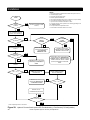
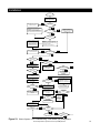
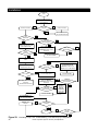
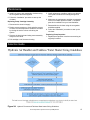
NOTES:
1
2
3
4
5
6
7
8
START
SYSTEM
PURGED
NO
Pipe system between Tankless Water Heater and Hyronic Furnace ‡
Leak check piping system
Purge and prime plumbing system
Perform required electrical work
Check system operation with power to condensing unit off (if installed)
Control board is sometimes refered to as 'PCB'
Hyronic Furnace is sometimes refered to as 'RHF'
Typical for all check, ensure system is in the following operating mode:
AC / SINGLE STAGE
RETURN TO PURGE & PRIME
STEPS ‡
9 For Amp loads refer to specification sheet
10 Thermostat is sometimes refered to as 'T'STAT'
YES
WITH DOOR SWITCH CLOSED
(SET SYSTEM IN HEATING
MODE - CALL FOR HEAT)
YES
NO
IS 'LED' RAPID
FLASH
CONSISTENT
NO
YES
NO
CHECK BREAKER AND POWER
SUPPLY
IS POWER
SUPPLY OK
YES
IS 'LED'
RAPIDLY
FLASHING
IS 'LED' ON
STEADY 'LED' FLASH - NORMAL
OPERATION OR STAND-BY
MODE AWAITING
THERMOSTAT CALL
DOMESTIC HOT WATER
DEMAND PRESENT –SYSTEM
ON HOLD - SEARCH MODE
NO
INCONSISTENT RAPID FLASH (PULSATING
PUMP OPERATION)– WRONG SHUNT
POSITION - REFER TO FIG.14 HYDRONIC
FURNACE CONTROL BOARD, JUMPER
(SHUNT) POSITION'P7' TO BE IN 'FS'
MODE
YES
RECTIFY SUPPLY VOLTAGE
PROBLEM(S) ANDRETURN TO
START
CHECK VOLTAGE ACROSS'L1'
AND 'L2'
NO
VAC = 115V +/-
CHECK SYSTEM WIRING
AGAINST WIRING DIAGRAM RECTIFY PROBLEM(S)
CHECK FOR LOOSE OR
BROKEN WIRE
YES
CHECK DOOR SWITCH, IF
DEFECTIVE, REPLACE SAME
AND RETURN TO START
NO
L1/L2 = 115V +/-
YES
GO TO 24 VOLTS
TROUBLESHOOTING CHART
NO
IS 'LED' ON
YES
‡ Refer to plumbing section in this manual
Figure 20: Hydronic Furnace Start-Up and ‘LED’ Troubleshooting - Flow Sensor (FS Configuration)
20
Rinnai Corporation Hydronic Furnace (37AHB) Manual
Installation
(
)
START
WITH DOOR SWITCH CLOSED
(SET SYSTEM IN HEATING
MODE; CALL FOR HEAT)
NO
GO TO RHF START-UP & 'LED'
TROUBLESHOOTING
IS 'LED' ON
YES
PULSING FLASH WITH PUMP AND FAN
ENERGIZED (associated with contactor
clicking sound) - WRONG SHUNT POSITION
FOR OPERATING MODE - REFER TO
FIG.14; CHANGE SHUNT POSITION AND
RETURN TO START
YES
STEADY 'LED'
FLASH
NORMAL OPERATION OR
STAND-BY MODE (AWAITING
THERMOSTAT CALL)
NO
'LED' FLASH
CODE
TO ISOLATE CAUSE: ENSURE
THAT SYSTEM IS PURGED AND
ALL FAUCETS AND OTHER
WATER CONSUMING
EQUIPMENT IS OFF (FLOW TO
RHF SHOULD BE ≥ 1 GPM)
RAPID FLASH - PUMP NOT ENERGIZED CAUSES:
1. SEARCH MODE (INSUFFICIENT FLOW);
2. NO POWER TO PUMP ;
3. NO POWER TO FLOW SENSOR
NO
GO TO CIRCULATING PUMP
115 v TROUBLESHOOTING
YES
STEADY 'LED'
FLASH
YES
FAN
ENERGIZED
YES
FAN AMP DRAW
NORMAL
NO
ADJUST THERMOSTAT SET
TEMPERATURE HIGHER THAN
ROOM TEMPERATURE
FAN
ENERGIZED
YES
NO
CHECK CAPACITOR; IF
DEFECTIVE, REPLACE
COMPONENT AND RE-CHECK
AMP DRAW
FAN AMP DRAW
NORMAL
YES
NO
YES
CHECK FAN MOTOR; IF
DEFECTIVE REPLACE
COMPONENT
NO
CHECK FOR LOOSE OR BROKEN
WIRES
YES
CHECK VOLTS ACROSS 'FAN'
CONNECTIONS ON PCB ('COOLHI' AND 'N4')
NO
FAN MOTOR
ENERGIZED
YES
VAC = 115V +/-
CONNECT FAN DIRECTLY TO
115 VAC POWER SUPPLY
(1) RECTIFY WIRING PROBLEM(S)
(2) CHECK MOTOR AND
CAPACITOR; IF DEFECTIVE,
REPLACE FAULTY COMPONENT(S)
RETURN TO START
NO
CHECK CAPACITOR; IF
DEFECTIVE REPLACE
COMPONENT AND RE-CHECK
AMP DRAW
PROBLEM(S) WITH 24V TO PCB
- GO TO 24V
TROUBLESHOOTING CHART
YES
FAN AMP DRAW
NORMAL
NO
NO
FAN AMP DRAW
NORMAL
CHECK FAN
MOTOR; IF
DEFECTIVE
REPLACE
COMPONENT
AND RE-CHECK
AMP DRAW
YES
RETURN TO START
RECONNECT WIRES AND
CONFIRM THAT WIRING IS AS
PER WIRING DIAGRAMS
CONTACT TECH.
SUPPORT
NO
SYSTEM
WORKING
YES
YES
FINISH
SYSTEM
WORKING
NO
Figure 21: Blower System 115V Troubleshooting - Flow Sensor (FS) Configuration
Rinnai Corporation Hydronic Furnace (37AHB) Manual
21
Installation
START
WITH DOOR SWITCH CLOSED
(SET SYSTEM IN HEATING MODE
-CALL FOR HEAT)
YES
YES
STEADY 'LED' FLASH
RAPID 'LED' FLASH
IS 'LED' ON
NO
GO TO RFH START-UP &
'LED' TROUBLESHOOTING
YES
PUMP
ENERGIZED
PUMP AMP
DRAW NORMAL
NO
ADJUST THERMOSTAT SET
TEMPERATURE HIGHER THAN
ROOM TEMPERATURE
PUMP
ENERGIZED
YES
NO
CHECK CAPACITOR; IF
DEFECTIVE, REPLACE
COMPONENT AND RE-CHECK
AMP DRAW
PUMP AMP
DRAW NORMAL
NO
YES
REPLACE PUMP MOTOR AND
RETURN TO START
NO
CHECK FOR LOOSE OR BROKEN
WIRES
YES
CHECK VOLTS ACROSS 'PUMP'
CONNECTIONS ON PCB
NO
PUMP MOTOR
ENERGIZED
YES
VAC = 115V +/-
CONNECT PUMP DIRECTLY TO
115 VAC POWER SUPPLY
(1) RECTIFY WIRING PROBLEM(S)
(2) CHECK MOTOR AND
CAPACITOR; IF DEFECTIVE,
REPLACE FAULTY COMPONENT(S)
RETURN TO START
NO
CHECK CAPACITOR; IF
DEFECTIVE REPLACE
COMPONENT AND RE-CHECK
AMP DRAW
PROBLEM(S) WITH 24V TO PCB
- GO TO 24V
TROUBLESHOOTING CHART
YES
PUMP AMP
DRAW NORMAL
NO
NO
PUMP AMP
DRAW NORMAL
CHECK PUMP
MOTOR; IF
DEFECTIVE
REPLACE
COMPONENT
AND RE-CHECK
AMP DRAW
YES
RETURN TO START
RECONNECT WIRES AND
CONFIRM THAT WIRING IS AS
PER WIRING DIAGRAMS
CONTACT TECH.
SUPPORT
NO
SYSTEM
WORKING
YES
YES
FINISH
SYSTEM
WORKING
NO
Figure 22: Circulating Pump 115V Troubleshooting - Flow Sensor (FS) Configuration
22
Rinnai Corporation Hydronic Furnace (37AHB) Manual
YES
Installation
START
WITH DOOR SWITCH CLOSED
(SET SYSTEM IN HEATING
MODE -CALL FOR HEAT)
NO
YES
GO TO HYDRONIC FURNACE START UP
AND 'LED' TROUBLESHOOTING
IS 'LED' ON
24V BETWEEN THERMOSTAT AND PCB
CHECK TRANSFORMER FOR
CORRECT VOLTAGES
PRI:VAC = 115V +/SEC: VAC = 24V +/-
NO
(1) CHECK FOR WIRING PROBLEM(S)
(2) CHECK TRANSFORMER; IF DEFECTIVE,
REPLACE FAULTY COMPONENT
NO
(1) CHECK FOR WIRING PROBLEM(S)
(2) CHECK FUSE; IF DEFECTIVE,
REPLACE FAULTY COMPONENT
YES
CHECK 3 AMP
FUSE; IS FUSE
INTACT
YES
CHECK T'STAT FOR CONTINUITY
WITH OHM METER BETWEEN
'R' AND 'W'
NO
IS THERE
CONTINUITYAT
T'STAT
ENSURE THAT T'STAT IS IN
HEATING MODE AND RECHECK
FOR CONTINUITY
YES
CHECK FOR WIRING
PROBLEM(S) AND REPAIR OR
REPLACE AND RETURN TO
START
CHECK FOR 24 V ACROSS
'WH/FS' PINS
YES
IS THERE
CONTINUITYAT
T'STAT
NO
NO
CHECK PCB; IF DEFECTIVE
REPLACE COMPONENT AND
RETURN TO START
VAC = 24V +/-
CHECK THERMOSTAT; IF
DEFECTIVE REPLACE
COMPONENT
YES
NO
CONTACT TECH. SUPPORT
SYSTEM
WORKING
YES
FINISH
24V BETWEEN CONDENSING UNIT AND PCB
If a condensing unit and cased coil set is used in conjunction with the Rinnai Hydronic Furnace for cooling,
refer to air conditioning manufacturer's instructions for hook-up and troubleshooting details.
Figure 23: 24V Troubleshooting - Flow Sensor (FS) Configuration
Rinnai Corporation Hydronic Furnace (37AHB) Manual
23
Sequence of Operation
SEQUENCE OF OPERATION:
Single-Stage Heat-Pump (HP) Cooling Demand:
NOTE: Furnace control must be grounded for proper
operation; control is grounded through green
wire routed to control box screw.
When the thermostat calls for cooling (Y and O), the
control waits for the 1 second cooling on delay period
and energizes the COOL_HI blower tap.
STANDBY MODE:
When the thermostat removes the call for cooling (Y
and O), the control de-energizes the COOL_HI blower
tap after a cooling off delay period of 30 seconds.
All control outputs are off and the control is waiting for
a thermostat demand. The control initiates action
when a thermostat call is received.
COOLING MODE:
Single-Stage Air-Conditioning (A/C) Cooling
Demand:
When the thermostat calls for cooling (Y), the control
energizes the COOL_HI blower tap after a 1 second
on delay period.
When the thermostat removes the call for cooling (Y),
the control de-energizes the COOL_HI blower tap after
a cooling off delay period of 30 seconds.
A call for cooling has priority over a thermostat blower
demand.
If a call for heat (W) exists with a call for cooling, the
call for heat shall proceed as normal except the blower
remains energized on the COOL_HI speed tap. If the
call for cool goes away while a call for heat exists, the
cooling off delay is canceled and the blower operation
reverts to the heat cycle.
Two-Stage A/C Cooling Demand:
When the thermostat calls for cooling (Y), the control
waits for a 1 second cooling on delay period and
energizes the COOL_LO blower tap. If a 2nd stage
cooling (Y2) call is sensed, the control de-energizes
the COOL_LO blower tap and energizes the COOL_HI
blower tap after a 1 second delay.
When the thermostat removes the call for 2nd stage
cooling (Y2), the control de-energizes the COOL_HI
blower tap and energizes the COOL_LO blower tap.
When the thermostat removes the call for cooling (Y),
the control de-energizes the COOL_LO blower tap
after a cooling off delay period of 30 seconds.
If a call for heat (W) exists with a call for 2nd stage
cooling, the call for heat shall proceed as normal
except the blower remains energized on the COOL_HI
speed. If the call for cool goes away while a call for
heat exists, the cooling off delay is canceled and the
blower operation reverts to the heat cycle.
24
A call for cooling has priority over a thermostat blower
demand.
If a call for emergency heat (W) exists with a call for
cooling, the call for heat shall proceed as normal
except the blower remains energized on the COOL_HI
speed tap. If the call for cool goes away while a call
for emergency heat exists, the cooling off delay is
canceled and the blower operation reverts to the heat
cycle.
Two-Stage HP Cooling Demand:
When the thermostat calls for cooling (Y and O), the
control waits for the 1 second cooling on delay period
and energizes the COOL_LO blower tap. If a second
stage cooling (Y2) call is sensed, the control deenergizes the COOL_LO blower tap and energizes the
COOL_HI blower tap after the 1 second delay.
When the thermostat removes the call for 2nd stage
cooling (Y2), the control de-energizes the COOL_HI
blower tap and energizes the COOL_LO blower tap.
When the thermostat removes the call for cooling (Y),
the control de-energizes the COOL_LO blower tap
after a cooling off delay period of 30 seconds.
If a call for emergency heat (W) exists with a call for
2nd stage cooling, the call for heat shall proceed as
normal except the blower remains energized on the
COOL_HI speed. If the call for cool goes away while a
call for emergency heat exists, the 2nd stage cooling
off delay is canceled and the blower operation reverts
to the heat cycle.
HEATING MODE:
Heating Operation: Air-Conditioning (A/C) Mode Configured for Flow Sensor (FS) Input:
Circulating Pump Operation:
On a call for heating, terminal “W” of the thermostat is
energized. The control monitors the FS input and
energizes the circulating pump if the FS signal is
present.
Rinnai Corporation Hydronic Furnace (37AHB) Manual
Sequence of Operation
If the FS signal is NOT present, the control will
energize the circulating pump for 60 seconds in an
attempt to activate the Flow Sensor (FS). If the FS
signal does not become active during the time, the
control will de-energize the circulating pump for 60
seconds and then start another 60 seconds with the
circulating pump energized to try to activate the Flow
Sensor. Sequential attempts to activate the Flow
Sensor will use 60 second, 120 second and 180
second de-energized periods for the circulating pump.
The de-energized period will circle back to the original
60 second off period following sequential unsuccessful
energized attempt to activate the Flow Sensor. During
this time the Status LED will rapidly flash, indicating
that a heat demand is present, but not being satisfied
because of the state of the FS input signal.
Heat Blower ON Delay:
The control waits for 25 seconds after the circulator
pump is energized (and FS signal is present) and then
energizes the indoor blower heat speed and the
humidifier output.
If the thermostat demand for heat is removed, the
control de-energizes the circulating pump, and runs
the heat speed blower and humidifier through the
selected blower off delay as defined by the dip switch
settings in Figure 15.
Steady Heat:
Control inputs are continuously monitored to ensure
the call for heat remains.
If the thermostat demand for heat is removed, control
operation proceeds to the operation described in “Heat
Blower ON delay” section above.
If the FS input becomes absent during steady state
heating, the sequence in “Circulating Pump Operation”
section above will become active and the blower off
delay will run.
If the FS input signal returns within the same heating
demand period (W), the control will begin jogging the
circulator pump as described in “Circulating pump
Operation” section, normal heating operation will
resume.
Heat Blower OFF Delay:
When the heating thermostat demand (W) is removed,
the control de-energizes the circulating pump and then
de-energizes the indoor blower motor and humidifier
after a delay time as defined by the dip switch settings
in Figure 15.
Blower timing begins when the thermostat is satisfied.
The control returns to standby when the blower off
time is complete.
If the thermostat call for heat returns before the blower
off delay is complete, the control re-energizes the
circulating pump and resumes a normal heating
sequence.
Heating Operation: Heat-Pump (HP) Mode Configured for Flow Sensor (FS) Input:
Single-Stage HP Demand - Call for Heat:
The thermostat calls for heat by connecting (Y and R).
The control will proceed to the Heat Blower ON Delay
when a single stage heat demand exists.
The Heat Pump is the primary source of heating in this
mode.
Blower ON Delays:
The control waits for 1 second and then energizes the
COOL_HI tap if and the humidifier output. If the
thermostat demand for heat is removed, the control
runs the COOL_HI tap and humidifier through a fixed
30 second blower off delay.
Steady Heat:
Control inputs are continuously monitored to ensure
the call for heat remains.
If the thermostat demand for heat is removed, control
operation proceeds to the operation described in the
“Blower On and Off Delays” section.
The Heat Pump is the primary source of heating in this
mode.
Second Stage HP Demand – Call for Heat:
After the control enters into a Steady Heat mode, the
second stage heating demand (Y2) input is monitored.
If a (Y2) demand is sensed, the COOL_HI blower
speed will be energized. If the (Y2) demand becomes
absent, the COOL_HI blower speed will immediately
be de-energized and the COOL_LO blower speed will
again be energized.
Heat-Pump Emergency Heat Demand:
The Emergency Heat (W) input is continually
monitored, and is a higher priority than single or 2stage heating demands. If the Flow Sensor (FS) input
signal is present with a call for emergency heat (W),
the circulator pump will immediately be energized.
Rinnai Corporation Hydronic Furnace (37AHB) Manual
25
Sequence of Operation
If the FS input signal remains (indicating that there is
adequate hot water flow) the circulator pump will
remain energized, the HEAT blower speed and HUM
outputs will then be energized. If the emergency heat
demand (W) is removed, the HEAT blower speed will
immediately be de-energized and the blower will return
to the appropriate speed based on any remaining
thermostat demand.
If the FS signal is NOT present, the control will
energize the circulating pump for 60 seconds in an
attempt to activate the Flow Sensor (FS). If the FS
signal does not become active during the time, the
control will de-energize the circulating pump for 60
seconds and then start another 60 seconds with the
circulating pump energized to try to activate the Flow
Sensor. Sequential attempts to activate the Flow
Sensor will use 60 second, 120 second and 180
second de-energized periods for the circulating pump.
The de-energized period will circle back to the original
60 second off period following sequential unsuccessful
energized attempt to activate the Flow Sensor. During
this time the Status LED will rapidly flash, indicating
that a heat demand is present, but not being satisfied
because of the state of the FS input signal.
Heat Blower OFF Delay:
When the heating thermostat demand is removed, the
control immediately de-energizes the circulating pump
and then de-energizes the indoor blower motor and
humidifier after a fixed 30 second blower off delay.
Blower timing begins when the thermostat is satisfied.
The control returns to standby when the blower off
time is complete.
If the thermostat call for emergency heat returns
before the blower off delay is complete, the control
resumes an emergency heating sequence as defined.
Off Season Circulation Timer
All Rinnai® Hydronic Furnace models are equipped
with a circulation timer. It is normal operation for these
models to automatically run the circulation pump for a
period of two minutes intermittently every six hours if
there has not been a call for heat within the said six
hours.
The unit also incorporates the unique feature of
learning the household schedule to determine the best
six hour intervals (periods of least flow interruption) to
run the circulator timer.
If the FS input signal again becomes present within
the same emergency heating demand (W), the pump
will begin jogging (as described in the above
paragraph), normal emergency heating operation will
resume.
Maintenance
Repairs should be performed by a qualified service
technician. The appliance should be inspected
annually by a qualified service technician. Verify
proper operation after servicing.
The supply and return air ducts should be inspected at
least annually for blockages or damage.
MOTORS
CLEANING
It is important that compartments, filter, and circulating
air passage ways of the appliance be kept clean.
Clean as follows:
1. Turn off and disconnect electrical power. Allow to
cool.
2. Replace the air filter. (Should be done at least
quarterly. Refer to the Specifications section for
sizes.)
3. Use pressurized air to remove dust from the
components.
4. Use soft dry cloth to wipe cabinet.
26
SUPPLY AND RETURN AIR DUCT SYSTEMS
Both the fan and pump motors are permanently
lubricated and do not need periodic lubrication. Keep
free of dust and dirt by cleaning annually.
INTEGRAL CIRCULATOR PUMP
Replacing Pump Motor Assembly:
1. Disconnect the electrical supply.
2. Reduce system pressure to 0 psi and allow system
to return to room temperature. Isolate the circulator
by closing the service valves or draining the system.
3. Remove the body bolts and swing motor assembly
away from the volute.
Rinnai Corporation Hydronic Furnace (37AHB) Manual
Maintenance
4. Install new motor, and reassemble circulator using
the new gasket and bolts supplied.
5. Follow the “installation” procedure to start up the
circulator.
Replacing Pump Cartridge Assembly:
1. Disconnect the electrical supply.
2. Reduce system pressure to 0 psi and allow system
to return to room temperature. Isolate the circulator
by closing the service valves or draining the
system.
3. Remove the body bolts and swing motor assembly
away from the volute.
4. Pull cartridge out of the motor housing.
5. Install replacement cartridge, making sure that the
cover plate is between the cartridge flange and
motor.
6. Make sure the replacement cartridge corresponds
to the full circulator product number. A complete
parts list is available from your local distributor.
7. Reassemble the circulator using the new gasket
and bolts supplied.
8. Follow the “Installation” procedure to start up the
circulator.
Replacing Pump Capacitor:
1. Replacement capacitor must have same rating as
originally furnished.
Selection Guide
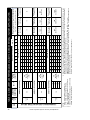
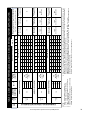
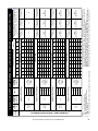
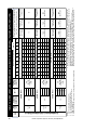
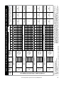
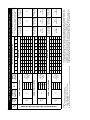
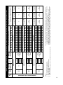
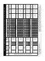
Figure 24: Hydronic Furnace and Tankless Water heater Sizing Guidelines
Rinnai Corporation Hydronic Furnace (37AHB) Manual
27
Selection Guide
GENERAL UNIT SELECTION PROCEDURE (WITH
EXAMPLE)
I.
Define hot water load for the total required
domestic hot water usage:
To help with the sizing and selection of your new
Rinnai Tankless Water Heater (TWH), refer to our
Website at: http://www.rinnai.us or contact Rinnai’s
Application Engineering Department at: 800-621-9419
As an example let us assume that the selected Rinnai
Tankless Water Heater for your whole house solution
is the REU-KA2530FFUD-US (RC80HPi) and your
calculated heat gain and heat loss values are as
stated in section II.
Determining cooling and heating
requirements for the given structure:
The ACCA's Manual J Residential Load Calculation
method is the established trade standard, approved by
ANSI, for the correct sizing and selection of Heating,
Ventilation, Air-Conditioning and Refrigeration
(HVACR) equipment in residential homes. Refer to
Manual J latest edition; the text in question offers an
all-inclusive new approach to ensure that Indoor Air
Quality (IAQ) systems are as efficient, safe, and
healthy as possible. Visit the Air Conditioning
Contractors of America website at: http://
www.acca.org or contact a qualified HVACR
contractor for further assistance.
pressure required. From the given example, note the
Wet Coil Pressure Drop (from the field supplied
Evaporative Cased Coil Installation Instructions), and
the Filter Pressure Drop. Determine both static
pressures at 1200 CFM:
Wet Coil Pressure Drop……0.21 in. WC (From Coil
Manufacturer’s Installation Instructions).
External Static Pressure…...0.2 in. WC (Ductwork
etc.)
Filter Pressure Drop………..0.0 in. WC
(0.0 inches if the included Rinnai filter is used; 0.08 if
another filter is used. Refer to the filter’s
manufacturer’s instructions).
II.
Assumptions:
Required Cooling Capacity ……….……..34,500 Btuh
(Total Capacity)
Required Heating Capacity…………..…..58,000 Btuh
Evaporator Air Quantity………………..…1200 CFM
Calculated Ductwork ESP………….…….0.2 in. WC
Electrical Characteristics…………………15-1-60
III.
Determine total external static pressure (ESP)
at design conditions:
Before using the Air Delivery and Capacity Charts
(Table 5.0 thru 5.17), determine the total static
Total Static Pressure..….... 0.49 in. WC
IV. Select unit based on required cooling
capacity airflow:
For an initial selection, choose a unit size that will
provide the required airflow. Refer to Tables 5.3 - Air
Delivery and Capacity Chart. Note that at 0.5 ESP the
37AHB06012KA5 unit will deliver 1225 cfm when
configured for HIGH Speed (Tap 1).
V.
Select heating capacity of unit to provide the
requisite design condition:
From the nominal capacity section of said table; the
37AHB060 units (Table 5.3), note that the unit
37AHB06012KA5 (as selected above) when matched
with the REU-KA2530FFUD (RC80HPi) TWH will
provide 58.1 MBH (58,100 Btuh) at an entering water
temperature (to Hydronic furnace) of 150 OF.
VI. Select unit that corresponds to power source
available:
Refer to Model Number Nomenclature; note that the
eleventh digit denotes the voltage code; therefore the
“K” model (37AHB06012KA5) unit is the unit that
should be selected for the above stated hypothetical
conditions. This unit is designed to operate at
115/120v -1ph - 60hz.
Air Distribution Guide
HIGH VELOCITY DUCT SYSTEMS:
A high velocity air delivery system employs higher air
velocities and static than that requisite for a
conventional ducting system. Specifically, the design
of such system requires a compromise between
smaller duct sizes and increased fan pressure.
28
The updated Rinnai Hydronic Furnace (with ECM
technology) will sustain total external static pressures
(ESP) of up to 1.0 in. w. g.; still, it is incumbent upon
the designer to devise a system that will work within
the parameters hereafter set forth in this manual. To
satisfy the above, and to take maximum advantage of
the increased available pressure of said Rinnai
Rinnai Corporation Hydronic Furnace (37AHB) Manual
Air Distribution Guide
Hydronic Furnace, He/ She should adhere to the
following basic rules whenever possible.
1. Duct joints shall be, as a rule, sealed to prevent
leakage of air which may cause objectionable sound.
2. Round ducts are favored to rectangular (on the
supply side) as they offer greater rigidity and higher
efficiency.
3. Fitting selection and placement should also be
carefully studied as the correct fitting and its location
will avoid excessive pressure drops and likely noise
problems.
4. Figures 25 and 26 illustrate the critical distance as
regards high velocity ducting system design.
Additionally, when laying out the header section for a
typical high velocity system, the following factor must
be considered:
Unless space conditions dictate otherwise, the
take-off from the header should be made using a
90 o tee or 90 o conical tee rather than a 45 o tee.
By using 90o fittings, the pressure drop to the
branch throughout the system is more uniform. In
addition, two fittings are normally required when a
45 o tee is used and only one when a 90 o fitting is
used, resulting in lower first cost.
Practically speaking, the design of a high velocity
system is basically the same as a low velocity duct
system. If concerns about noise were not a factor,
duct runs could be sized according to the smallest
permissible duct diameter which would be governed
only by the available external static pressure. In
opposition, since noise reduction is paramount in
residential designs, the designer must take special
care to ensure that all duct sizes are compatible with
velocity limits that are associated with both the
discharge and return sides of the planned system.
To all intents and purposes, duct sizing calculations
are based on fan performance and air side accessory
pressure drop data that are provided by original
equipment manufacturers. The importance of
ensuring that the total pressure drop of the longest
circulation path does not exceed the available static
pressure and that velocities does not exceed the
recommended limits cannot be overstated as these
will ensure a quieter system that will deliver the
required capacity to a given space.
It is absolutely overriding for the designer to verify
available static pressure for both supply and return
ducts. The following tables (tables 3 and 4) provide
information about duct sizing (specific to hi-velocity
system) and the redesigned 37AHB series furnaces
respectively.
To employ table 3 the designer must have generated
at least the following information: total system required
airflow (in CFM), and maximum number of 3 inch
diameter supply legs based on 50 CFM per leg.
Table 4 “Specification Sheet” summarizes the
performance and other technical characteristics of the
37AHB series furnaces and their subsystems.
Some specification numbers are generated by
numerical methods and are therefore statistical means
based on the testing of three or more samples.
Use both tables in conjunction with good engineering
practice together with all codes and ordinances having
jurisdiction.
Figure 25:
Recommended Critical Distance between Elbows and 90O
Tees for a Typical High Velocity System.
Figure 26:
Recommended Critical Distance between Elbows and 90O
Conical Tees for a Typical High Velocity System.
Rinnai Corporation Hydronic Furnace (37AHB) Manual
29
30
1700 1600 1500 1400 1300 1200 1100 1050 1000
34
2300 2200 2100 2000 1900 1800 1700 1600 1500 1400 1300 1200 1100 1000
46
NOL
MAF
NOL
44
32
42
30
23
40
28
22
38
26
21
36
24
20
34
22
19
950
12
32
21
18
900
11
30
20
17
850
10
500
28
19
950
16
800
9
450
26
18
900
15
750
24
17
850
14
700
22
16
800
13
650
20
15
750
12
600
5
MAF
24
13
550
6
26
14
600
7
NOL
15
650
4
8
1300 1200 1150 1100 1050 1000
16
700
5
250
MAF
17
750
6
200
300
18
800
7
250
350
NOL
850
8
300
3
400
900
9
350
4
150
2
MAF
10
400
5
200
3
11
450
6
250
100
NOL
500
7
300
150
560
MAF
8
350
3
2
8
NOL
400
4
150
100
420
5
200
1
MAF
6
250
2
2
6
300
3
50
NOL
100
320
4
100
1
MAF
50
4
150
1
NOL
200
2
210
2
MAF
50
3
75
NOL
100
140
MAF
18
900
14
700
11
550
4
200
17
850
13
650
10
500
3
150
16
800
12
600
9
450
15
750
11
550
8
400
Maximum Airflow (CFM) with Maximum Number of 3" flex legs
Table 3: Quick Reference Hi‐Velocity Duct Sizing Chart
14
700
10
500
7
350
13
650
9
450
6
300
12
600
8
400
5
250
11
550
7
350
10
500
6
300
9
450
NOTES:
1. Calculations are based on airflow of 50 CFM for each 3 inch diameter flexible leg.
2. Calculations assume system is equipped with a standard add-on evaporative coil and allows for approximately 120 equivalent length of return ducting.
3. MAF – Maximum airflow (CFM).
4. NOL – Number of 3” diameter flexible legs.
5. If a more detailed duct sizing method is required, refer to one or more of the referenced documents or any other industry recognized standard.
LIST OF REFERENCES:
ACCA - Manual D (Residential Duct Systems)
ACCA - Flexible Duct Performance & Installation Standards
ASHRAE Handbook-Fundamentals
HRAI - Residential Air System Design Manual
SMACNA - HVAC System Duct Design Manual
16
14
12
10
8
7
6
5
4
Rigid Trunk Duct Diameter (inches)
320
250
200
175
140
120
100
90
60
Maximum Equivalent Duct Length (Feet)
Air Distribution Guide
Rinnai Corporation Hydronic Furnace (37AHB) Manual
Table 4: Hydronic Furnace’s Specifications
UNIT MODELS
Trade Name
RATING AND PERFORMANCE
Nominal Output Capacity (BTU/h) †
Air Side Temperature Rise Rate in oF
( 68ºF Entering Air @ 150ºF Entering Water)
External Static Pressure
Nominal Airflow (CFM)
37AHB04508KA5 37AHB06012KA5 37AHB07514KA5 37AHB09016KA5
AHB45
AHB60
AHB75
AHB90
Descriptor (Typ.)
45,000
60,000
75,000
90,000
Heat Speed
50
50
50
50
(in. W.C.)
Heating
Cooling Range
0 to 1.0
800 ‡
650 - 800
0 to 1.0
1200 ‡
650 - 1200
0 to 1.0
1400 ‡
1000 - 1600
0 to 1.0
1600 ‡
1200 - 1750
ELECTRICAL
Power Supply
Minimum Circuit Ampacity
Max. Rating of Overcurrent Protective Device
Maximum Fuse or CKT BKR Size
Transformer (24V)
V - HZ - PH
MCA
MOP (Calculated)
Amps
Printed Circuit Board
PCB
115-60-1
9.6
12.43
16.2
13.6
18
23.7
15
20
25
40 VA (Primary: 120 VAC / Secondary: 24 VAC)
INTEGRAL (with connections for A/C system, UV lamp, Humidifier, and
electronic air cleaner)
9.6
13.6
15
CONTROLS
Available Unit Configurations
Safety Door Switch
Blower Off Delay
Cool / Heat Blower On Delay
INDOOR BLOWER MOTOR
Type
Motor HP
Motor (Full Load Amps)
Run Capacitor
Volts-PH-HZ
CIRCULATING PUMP
Type
Volts-PH-HZ
Motor (Full Load Amps/Locked Rotor Amps)
Pump Motor HP
Run Capacitor
Maximum Working Pressure
Min/Max Fluid Temperature
HYDRONIC HEATING COIL
Coil Construction
Rows...Fins/In
Total Face Area
Approximate Internal Volume
PIPING CONNECTIONS - (QTY)
Type
Supply Diameter
Return Diameter
RETURN-AIR FILTERS
Filter Type (Throwaway)
UNIT WEIGHT
Shipping
Installed (with water)
A/C or HP
Single or Two Stage
FS or WH
Rated Voltage
Resistive Load
HTG/CLG
Varies
FLA
mfd/volts
Dip Switch Selectable (SW1)
Dip Switch Selectable (SW1)
Shunt Selectable (P-7)
125 VAC
21 Amp
Dip-switch Selectable/Fixed 30 Sec
Cool: 1 second / Heat: 25 seconds (see Sequence of Operations)
1/2
6.2
DIRECT DRIVE MOTOR (ECM)
1/2
3/4
6.2
8.5
N/A
115-1-60
1
11.5
N/A
mfd/volts
PSI
ºF (ºC)
Wet Rotor
115-1-60
1.8 / 2.6
1/8
14/250
125
120 (49) / 160 (71)
Sq. Ft.
3/8" OD copper tubes, aluminum fins, galvanized steel frame
2…16
2…16
3…14
3…15
2.3
2.6
2.8
3.3
FLA/LRA
Gallons
0.47
0.53
1.02
20 X 20 X 1
(2) 12 X 20 X 1
Copper Stubs
(1) 3/4
(1) 3/4
Inches
Inches
Inches ††
0.86
12 X 20 X 1
16 X 20 X 1
lbs
92
109
118
136
lbs
107
127
138
159
Rinnai is continually updating and improving products. Therefore, specifications are subject to change without prior notice.
†
Tested in accordance with ANSI/ASHRAE Standard 37-Latest edition.
Side intake filter to be (1) 20”x20”x1” typical for all models.
‡
Airflows shown are nominal (blower speeds are factory set). For air delivery
other than stated, refer to Air Delivery & Performance table.
Air filter pressure drop for non-standard filters must not exceed 0.08 in. wg.
†† Required filter sizes shown are based on the larger of the AHRI (Air
Conditioning & Refrigeration Institute) rated cooling airflow or the heating
airflow velocity of 300 ft/min for throwaway type or 450 ft/min for highcapacity type.
Rinnai Corporation Hydronic Furnace (37AHB) Manual
31
UNIT
SIZE
Rinnai Corporation Hydronic Furnace (37AHB) Manual
TAP 5
(L)
TAP 4
(M)
TAP 3
(H)
ECM
SPEED
TAP
EWT (OF)
160
150
140
160
150
140
1.5
160
150
140
130
120
AHB45 + RC98HPi(e)
2.0
130
120
AHB45 + RC98HPi(e)
2.0
130
120
AHB45 + RC98HPi(e)
SUPPORTS
COOLING CAP.
RANGE (TONS)
56.7
49.7
42.1
35.8
30.1
803
58.4
50.2
44.4
37.6
32.2
921
58.9
50.9
44.1
36.7
31.6
948
0
54.2
47.5
40.3
34.2
28.7
768
56.5
48.6
43.0
36.4
31.1
891
57.2
49.4
42.8
35.7
30.7
921
0.1
52.2
45.8
38.8
33.0
27.7
740
54.8
47.1
41.7
35.3
30.2
864
55.4
47.8
41.4
34.5
29.7
891
0.2
50.2
44.1
37.4
31.7
26.7
712
53.0
45.6
40.3
34.1
29.2
836
53.9
46.6
40.4
33.6
28.9
868
0.3
0.5
0.6
819
50.9
44.0
38.1
31.7
27.3
795
49.4
42.7
37.0
30.8
26.5
50.0
42.9
38.0
32.2
27.5
788
48.7
41.9
37.0
31.3
26.8
768
48.1
42.2
35.8
30.4
25.5
682
46.0
40.4
34.2
29.1
24.4
652
44.3
38.9
33.0
28.0
23.5
628
AIRFLOW (CFM)
51.5
44.3
39.2
33.1
28.4
812
AIRFLOW (CFM)
52.3
45.2
39.1
32.6
28.0
841
AIRFLOW (CFM)
0.4
42.1
36.9
31.3
26.6
22.3
596
47.1
40.4
35.8
30.3
25.9
742
48.0
41.4
35.9
29.9
25.7
772
0.7
External Static Pressure (ESP)
40.1
35.2
29.9
25.4
21.3
569
44.3
38.1
33.7
28.5
24.4
699
43.6
37.6
32.6
27.2
23.4
701
0.8
38.2
33.5
28.4
24.1
20.3
541
37.7
32.4
28.6
24.2
20.8
594
37.0
32.0
27.7
23.1
19.9
596
0.9
in. W.C.
36.0
31.6
26.8
22.7
19.1
510
35.5
30.5
27.0
22.8
19.5
559
35.2
30.4
26.4
22.0
18.9
567
1.0
16
20
TBD
See Note
16 6.
TBD
See Note
20 6.
TBD
See 13
Note 6.
TBD
See 16
Note 6.
TBD
See Note
6.
20
Minimum Legs @ Optimal Legs @ Maximum legs @
60 CFM/Leg
50 CFM/Leg
40 CFM/Leg
TBD
See Note
13 6.
Minimum Legs @ Optimal Legs @ Maximum legs @
60 CFM/Leg
50 CFM/Leg
40 CFM/Leg
13
Minimum Legs @ Optimal Legs @ Maximum legs @
60 CFM/Leg
50 CFM/Leg
40 CFM/Leg
Number of 3" Diameter Branch Legs applicable to High
Velocity Systems Only. Used only if methods other
than Table 3 is used to determine duct sizes.
6. Number of 3” diameter legs specified in table above is for rating point only (i.e. at External Static Pressure of 0.5 in. wc. and
speed TAP3, TAP1, TAP2 , TAP2 for AHB45, AHB60, AHB75, AHB90 respectively). Final leg count is to be determined by
the installing contractor and is to be based on the following formula:
NUMBER OF LEGS = TOTAL AVAILABLE CFM (AT THE SPECIFIC ESP) / DESIRED CFM per LEG (40, 50, or 60 CFM)
Example: Given the design point for AHB045 of 0.8 ESP, Low fan speed (Tap5). From table 5.0, available CFM is 569 and
the desired CFM per leg is 50 CFM.
Therefore, Number of Legs = 569/50 = 11.38 rounded down to 11.
NET
HEATING
CAPACITY
(MBH)
NET
HEATING
CAPACITY
(MBH)
NET
HEATING
CAPACITY
(MBH)
NOMINAL
HEATING
CAPACITY
TABLE 5.0: AIR DELIVERY AND PERFORMANCE DATA (BOTTOM OR SIDE RETURN w/ FACTORY SUPPLIED FILTER)
NOTES:
1. EWT - Entering Water Temperature (F).
2. CFM - Airflow in (Cubic Feet per Minute).
3. Legs - 3 inch diameter flexible ducts to diffusers.
4. 1 MBH = 1000 BTU/H.
5. Shaded box represents rating point; refer to wiring
diagram for factory set speed taps.
37AHB04508KA5 + REU-KA3237FFUD (WD)-US
32
Rinnai Corporation Hydronic Furnace (37AHB) Manual
33
UNIT
SIZE
TAP 5
(L)
TAP 4
(M)
TAP 3
(H)
ECM
SPEED
TAP
EWT (OF)
160
150
140
160
150
140
1.5
160
150
140
130
120
AHB45 + RC80HPi(e)
2.0
130
120
AHB45 + RC80HPi(e)
2.0
130
120
AHB45 + RC80HPi(e)
SUPPORTS
COOLING CAP.
RANGE (TONS)
55.0
49.0
41.1
35.3
31.2
803
58.7
52.1
45.8
37.2
31.8
921
59.3
52.3
46.0
37.4
31.4
948
0
52.6
46.8
39.3
33.8
29.8
768
56.7
50.4
44.3
36.0
30.8
891
57.6
50.8
44.7
36.3
30.5
921
0.1
50.7
45.1
37.8
32.6
28.7
740
55.0
48.9
42.9
34.9
29.9
864
55.7
49.1
43.2
35.2
29.5
891
0.2
48.7
43.4
36.4
31.3
27.7
712
53.2
47.3
41.6
33.8
28.9
836
54.3
47.9
42.1
34.3
28.7
868
0.3
0.5
0.6
819
51.2
45.2
39.7
32.3
27.1
795
49.7
43.9
38.6
31.4
26.3
50.2
44.6
39.2
31.8
27.2
788
48.9
43.4
38.2
31.0
26.5
768
46.7
41.6
34.9
30.0
26.5
682
44.6
39.7
33.3
28.7
25.3
652
43.0
38.3
32.1
27.6
24.4
628
AIRFLOW (CFM)
51.7
45.9
40.4
32.8
28.1
812
AIRFLOW (CFM)
52.6
46.4
40.8
33.2
27.8
841
AIRFLOW (CFM)
0.4
40.8
36.3
30.5
26.2
23.2
596
47.3
42.0
36.9
30.0
25.6
742
48.3
42.6
37.4
30.5
25.6
772
0.7
External Static Pressure (ESP)
38.9
34.7
29.1
25.0
22.1
569
44.5
39.5
34.7
28.2
24.2
699
43.8
38.7
34.0
27.7
23.2
701
0.8
37.0
33.0
27.7
23.8
21.0
541
37.8
33.6
29.5
24.0
20.5
594
37.3
32.9
28.9
23.5
19.7
596
0.9
in. W.C.
34.9
31.1
26.1
22.5
19.8
510
35.6
31.6
27.8
22.6
19.3
559
35.5
31.3
27.5
22.4
18.8
567
1.0
16
20
TBD
See Note
16 6.
TBD
See Note
20 6.
TBD
See Note
13 6.
TBD
See Note
16 6.
TBD
See Note
20 6.
Minimum Legs @ Optimal Legs @ Maximum legs @
60 CFM/Leg
50 CFM/Leg
40 CFM/Leg
TBD
See Note
13 6.
Minimum Legs @ Optimal Legs @ Maximum legs @
60 CFM/Leg
50 CFM/Leg
40 CFM/Leg
13
Minimum Legs @ Optimal Legs @ Maximum legs @
60 CFM/Leg
50 CFM/Leg
40 CFM/Leg
Number of 3" Diameter Branch Legs applicable to High
Velocity Systems Only. Used only if methods other
than Table 3 is used to determine duct sizes.
6. Number of 3” diameter legs specified in table above is for rating point only (i.e. at External Static Pressure of 0.5 in. wc. and
speed TAP3, TAP1, TAP2 , TAP2 for AHB45, AHB60, AHB75, AHB90 respectively). Final leg count is to be determined by
the installing contractor and is to be based on the following formula:
NUMBER OF LEGS = TOTAL AVAILABLE CFM (AT THE SPECIFIC ESP) / DESIRED CFM per LEG (40, 50, or 60 CFM)
Example: Given the design point for AHB045 of 0.8 ESP, Low fan speed (Tap5). From table 5.0, available CFM is 569 and
the desired CFM per leg is 50 CFM.
Therefore, Number of Legs = 569/50 = 11.38 rounded down to 11.
NET
HEATING
CAPACITY
(MBH)
NET
HEATING
CAPACITY
(MBH)
NET
HEATING
CAPACITY
(MBH)
NOMINAL
HEATING
CAPACITY
TABLE 5.1: AIR DELIVERY AND PERFORMANCE DATA (BOTTOM OR SIDE RETURN w/ FACTORY SUPPLIED FILTER)
NOTES:
1. EWT - Entering Water Temperature (F).
2. CFM - Airflow in (Cubic Feet per Minute).
3. Legs - 3 inch diameter flexible ducts to diffusers.
4. 1 MBH = 1000 BTU/H.
5. Shaded box represents rating point; refer to wiring
diagram for factory set speed taps.
37AHB04508KA5 + REU-KA2530FFUD(WD)-US
UNIT
SIZE
Rinnai Corporation Hydronic Furnace (37AHB) Manual
TAP 5
(L)
TAP 4
(ML)
TAP 2
(MH)
TAP 1
(H)
ECM
SPEED
TAP
EWT (OF)
160
150
140
160
150
140
160
150
140
1.5
160
150
140
130
120
AHB60 + RC98HPi(e)
2.0
130
120
AHB60 + RC98HPi(e)
2.5
130
120
AHB60 + RC98HPi(e)
3.0
130
120
AHB60 + RC98HPi(e)
SUPPORTS
COOLING CAP.
RANGE (TONS)
NET
HEATING
CAPACITY
(MBH)
NET
HEATING
CAPACITY
(MBH)
NET
HEATING
CAPACITY
(MBH)
NET
HEATING
CAPACITY
(MBH)
NOMINAL
HEATING
CAPACITY
0.1
0.2
0.3
0.5
0.6
AIRFLOW (CFM)
0.4
0.7
0.8
0.9
in. W.C.
70.8
62.9
54.2
46.8
39.9
69.6
61.8
53.3
46.0
39.3
68.2
60.6
52.2
45.1
38.5
65.8
58.4
50.4
43.5
37.1
61.2
53.9
47.4
44.6
34.3
844
64.6
57.8
50.0
42.6
36.2
971
68.8
61.3
52.1
44.5
38.7
58.8
51.7
45.4
42.8
32.9
810
62.7
56.0
48.5
41.4
35.1
942
67.6
60.3
51.2
43.8
38.0
53.3
56.4
60.7
54.1
46.0
39.3
34.1
984
59.0
52.6
44.7
38.2
33.2
54.4
48.6
42.0
35.9
30.5
817
52.2
46.6
40.3
34.4
29.2
784
50.6
44.6
39.2
36.9
28.4
698
48.3
42.5
37.3
35.1
27.0
665
45.4
40.0
35.1
33.1
25.5
626
AIRFLOW (CFM)
56.4
50.4
43.6
37.2
31.6
847
AIRFLOW (CFM)
62.6
55.8
47.5
40.5
35.2
42.2
37.1
32.6
30.7
23.6
581
50.0
44.7
38.6
33.0
28.0
751
57.2
51.0
43.4
37.0
32.2
955
62.8
55.7
48.0
41.5
35.4
38.7
34.0
29.9
28.2
21.7
533
47.6
42.5
36.8
31.4
26.6
715
56.2
50.1
42.6
36.3
31.6
937
59.6
52.9
45.6
39.4
33.6
36.6
32.2
28.3
26.6
20.5
504
45.3
40.5
35.0
29.9
25.3
680
54.4
48.5
41.2
35.2
30.6
908
55.1
48.9
42.2
36.4
31.1
33.8
29.8
26.1
24.6
18.9
466
42.7
38.2
33.0
28.2
23.9
642
41.4
36.9
31.3
26.8
23.3
690
47.8
42.4
36.6
31.6
26.9
889
1.0
24
30
24
TBD
See Note 6.
30
TBD
See Note 6.
TBD
See Note
24 6.
TBD
See Note
30 6.
TBD
See Note
20 6.
TBD
See Note
24 6.
TBD
See Note
30 6.
Minimum Legs @ Optimal Legs @ Maximum legs @
60 CFM/Leg
50 CFM/Leg
40 CFM/Leg
TBD
See Note
20 6.
Minimum Legs @ Optimal Legs @ Maximum legs @
50 CFM/Leg
60 CFM/Leg
40 CFM/Leg
20
TBD
See Note 6.
Minimum Legs @ Optimal Legs @ Maximum legs @
60 CFM/Leg
50 CFM/Leg
40 CFM/Leg
20
Minimum Legs @ Optimal Legs @ Maximum legs @
60 CFM/Leg
50 CFM/Leg
40 CFM/Leg
Number of 3" Diameter Branch Legs applicable to High
Velocity Systems Only. Used only if methods other
than Table 3 is used to determine duct sizes.
6. Number of 3” diameter legs specified in table above is for rating point only (i.e. at External Static Pressure of 0.5
in. wc. and speed TAP3, TAP1, TAP2 , TAP2 for AHB45, AHB60, AHB75, AHB90 respectively). Final leg count is
to be determined by the installing contractor and is to be based on the following formula:
NUMBER OF LEGS = TOTAL AVAILABLE CFM (AT THE SPECIFIC ESP) / DESIRED CFM per LEG (40, 50, or 60 CFM)
Example: Given the design point for AHB045 of 0.8 ESP, Low fan speed (Tap5). From table 5.0, available CFM is
569 and the desired CFM per leg is 50 CFM. Therefore, Number of Legs = 569/50 = 11.38 rounded down to 11.
46.9
41.2
38.8
29.8
734
58.6
52.4
45.3
38.6
32.8
880
64.2
57.3
48.7
41.6
36.1
49.6
43.6
41.0
31.6
777
60.6
54.2
46.9
40.0
34.0
911
66.1
58.9
50.1
42.8
37.2
64.3
57.1
49.2
42.5
36.3
AIRFLOW (CFM)
67.0
59.5
51.3
44.3
37.8
1148 1128 1103 1072 1045 1012
72.2
64.1
55.2
47.7
40.7
1343 1318 1296 1270 1248 1225 1197 1168 1109 1025
0
External Static Pressure (ESP)
TABLE 5.2: AIR DELIVERY AND PERFORMANCE DATA (BOTTOM OR SIDE RETURN w/ FACTORY SUPPLIED FILTER)
NOTES:
1. EWT - Entering Water Temperature (F).
2. CFM - Airflow in (Cubic Feet per Minute).
3. Legs - 3 inch diameter flexible ducts to diffusers.
4. 1 MBH = 1000 BTU/H.
5. Shaded box represents rating point; refer to wiring diagram for factory set speed taps.
37AHB06012KA5 + REU-KA3237FFUD(WD)-US
34
Rinnai Corporation Hydronic Furnace (37AHB) Manual
35
UNIT
SIZE
TAP 5
(L)
TAP 4
(ML)
TAP 2
(MH)
TAP 1
(H)
ECM
SPEED
TAP
EWT (OF)
160
150
140
160
150
140
160
150
140
1.5
160
150
140
130
120
AHB60 + RC80HPi(e)
2.0
130
120
AHB60 + RC80HPi(e)
2.5
130
120
AHB60 + RC80HPi(e)
3.0
130
120
AHB60 + RC80HPi(e)
SUPPORTS
COOLING CAP.
RANGE (TONS)
NET
HEATING
CAPACITY
(MBH)
NET
HEATING
CAPACITY
(MBH)
NET
HEATING
CAPACITY
(MBH)
NET
HEATING
CAPACITY
(MBH)
NOMINAL
HEATING
CAPACITY
0.1
0.2
0.3
0.5
0.6
AIRFLOW (CFM)
0.4
0.7
0.8
0.9
in. W.C.
69.1
62.6
53.8
46.5
40.3
68.0
61.5
52.9
45.7
39.6
66.6
60.3
51.8
44.8
38.8
64.3
58.1
50.0
43.2
37.4
59.6
55.1
46.8
39.7
33.3
844
63.8
58.6
49.6
41.9
35.0
971
66.9
60.5
52.1
44.5
37.9
57.2
52.9
44.9
38.1
32.0
810
61.9
56.9
48.1
40.6
34.0
942
65.7
59.4
51.2
43.7
37.3
51.8
54.9
59.0
53.3
45.9
39.2
33.4
984
57.3
51.9
44.7
38.2
32.5
53.6
49.3
41.7
35.2
29.5
817
51.5
47.3
40.0
33.8
28.3
784
49.3
45.6
38.7
32.8
27.6
698
47.0
43.4
36.9
31.2
26.3
665
44.2
40.9
34.7
29.4
24.7
626
AIRFLOW (CFM)
55.6
51.1
43.2
36.5
30.5
847
AIRFLOW (CFM)
60.9
55.1
47.4
40.5
34.5
41.0
37.9
32.2
27.3
22.9
581
49.3
45.3
38.3
32.4
27.1
751
55.6
50.3
43.4
37.0
31.5
955
61.3
55.4
47.6
41.2
35.7
37.6
34.8
29.6
25.0
21.0
533
47.0
43.2
36.5
30.8
25.8
715
54.6
49.4
42.5
36.3
31.0
937
58.2
52.6
45.2
39.1
33.9
35.6
32.9
28.0
23.7
19.9
504
44.7
41.1
34.7
29.3
24.5
680
52.9
47.8
41.2
35.2
30.0
908
53.8
48.6
41.8
36.2
31.3
32.9
30.4
25.8
21.9
18.4
466
42.2
38.8
32.8
27.7
23.1
642
40.2
36.4
31.3
26.8
22.8
690
46.6
42.2
36.3
31.4
27.2
889
1.0
24
30
TBD
24 6.
See Note
TBD
30 6.
See Note
TBD
24
See Note
6.
TBD
30
See Note
6.
TBD
See Note
20 6.
TBD
See Note
24 6.
TBD
See Note
30 6.
Minimum Legs @ Optimal Legs @ Maximum legs @
60 CFM/Leg
50 CFM/Leg
40 CFM/Leg
TBD
20
See Note
6.
Minimum Legs @ Optimal Legs @ Maximum legs @
60 CFM/Leg
50 CFM/Leg
40 CFM/Leg
TBD
20 6.
See Note
Minimum Legs @ Optimal Legs @ Maximum legs @
60 CFM/Leg
50 CFM/Leg
40 CFM/Leg
20
Minimum Legs @ Optimal Legs @ Maximum legs @
60 CFM/Leg
50 CFM/Leg
40 CFM/Leg
Number of 3" Diameter Branch Legs applicable to High
Velocity Systems Only. Used only if methods other
than Table 3 is used to determine duct sizes.
6. Number of 3” diameter legs specified in table above is for rating point only (i.e. at External Static Pressure of 0.5
in. wc. and speed TAP3, TAP1, TAP2 , TAP2 for AHB45, AHB60, AHB75, AHB90 respectively). Final leg count is
to be determined by the installing contractor and is to be based on the following formula:
NUMBER OF LEGS = TOTAL AVAILABLE CFM (AT THE SPECIFIC ESP) / DESIRED CFM per LEG (40, 50, or 60 CFM)
Example: Given the design point for AHB045 of 0.8 ESP, Low fan speed (Tap5). From table 5.0, available CFM is
569 and the desired CFM per leg is 50 CFM. Therefore, Number of Legs = 569/50 = 11.38 rounded down to 11.
47.9
40.7
34.5
29.0
734
57.8
53.1
44.9
37.9
31.7
880
62.5
56.5
48.7
41.6
35.4
50.7
43.1
36.5
30.7
777
59.8
55.0
46.5
39.3
32.8
911
64.3
58.1
50.1
42.8
36.4
62.8
56.8
48.8
42.2
36.6
AIRFLOW (CFM)
65.5
59.2
50.9
44.0
38.1
1148 1128 1103 1072 1045 1012
70.4
63.7
54.8
47.4
41.0
1343 1318 1296 1270 1248 1225 1197 1168 1109 1025
0
External Static Pressure (ESP)
TABLE 5.3: AIR DELIVERY AND PERFORMANCE DATA (BOTTOM OR SIDE RETURN w/ FACTORY SUPPLIED FILTER)
NOTES:
1. EWT - Entering Water Temperature (F).
2. CFM - Airflow in (Cubic Feet per Minute).
3. Legs - 3 inch diameter flexible ducts to diffusers.
4. 1 MBH = 1000 BTU/H.
5. Shaded box represents rating point; refer to wiring diagram for factory set speed taps.
37AHB06012KA5 + REU-KA2530FFUD(WD)-US
UNIT
SIZE
Rinnai Corporation Hydronic Furnace (37AHB) Manual
TAP 4
(L)
TAP 3
(ML)
TAP 2
(MH)
TAP 1
(H)
ECM
SPEED
TAP
EWT (OF)
160
150
140
160
150
140
130
160
150
140
2.5
160
150
140
130
120
AHB75 + RC98HPi(e)
3.0
130
120
AHB75 + RC98HPi(e)
3.5
120
AHB75 + RC98HPi(e)
4.0
130
120
AHB75 + RC98HPi(e)
SUPPORTS
COOLING CAP.
RANGE (TONS)
NET
HEATING
CAPACITY
(MBH)
NET
HEATING
CAPACITY
(MBH)
NET
HEATING
CAPACITY
(MBH)
NET
HEATING
CAPACITY
(MBH)
NOMINAL
HEATING
CAPACITY
0.1
0.2
0.3
0.5
0.6
AIRFLOW (CFM)
0.4
0.7
0.8
0.9
in. W.C.
1.0
88.0
78.6
67.7
58.8
49.3
86.4
77.1
66.5
57.7
48.4
84.7
75.7
65.2
56.6
47.4
81.5
72.8
62.7
54.5
45.6
80.2
71.6
61.7
53.6
44.9
AIRFLOW (CFM)
83.3
74.3
64.1
55.6
46.6
78.8
70.4
60.7
52.7
44.1
77.4
69.1
59.6
51.7
43.3
75.5
67.5
58.1
50.5
42.3
74.1
66.1
57.0
49.5
41.5
87.4
78.1
68.5
58.2
50.1
85.5
76.3
67.0
56.9
49.0
83.5
74.6
65.4
55.6
47.8
80.1
71.5
62.7
53.3
45.9
78.2
69.9
61.3
52.1
44.8
AIRFLOW (CFM)
81.9
73.2
64.2
54.5
46.9
76.3
68.2
59.8
50.8
43.7
70.6
63.0
55.3
46.9
40.4
72.6
64.8
56.9
48.3
41.6
70.2
62.7
55.0
46.7
40.2
88.9
78.9
69.9
59.0
50.1
86.9
77.2
68.4
57.7
49.0
84.3
74.9
66.3
56.0
47.6
79.6
70.7
62.6
52.9
44.9
82.1
73.7
64.5
53.3
47.4
78.9
70.8
62.0
51.2
45.5
73.9
76.6
71.4
64.1
56.1
46.4
41.2
68.1
61.1
53.5
44.2
39.3
65.8
59.0
51.7
42.7
38.0
979
63.0
56.5
49.5
40.9
36.3
937
74.5
66.1
58.6
49.4
42.0
59.6
53.5
46.8
38.7
34.4
887
71.8
63.7
56.4
47.7
40.5
55.7
50.0
43.8
36.2
32.2
829
70.1
62.2
55.1
46.5
39.5
52.2
46.9
41.0
33.9
30.1
777
67.9
60.3
53.4
45.1
38.3
TBD
See Note
28 6.
TBD
See Note
35 6.
28
35
TBD
See Note
28 6.
TBD
See Note
35 6.
TBD
See Note
23 6.
TBD
See Note
28 6.
TBD
See Note
35 6.
Minimum Legs @ Optimal Legs @ Maximum legs @
60 CFM/Leg
50 CFM/Leg
40 CFM/Leg
TBD
See Note
23 6.
Minimum Legs @ Optimal Legs @ Maximum legs @
50 CFM/Leg
40 CFM/Leg
60 CFM/Leg
23
Minimum Legs @ Optimal Legs @ Maximum legs @
50 CFM/Leg
40 CFM/Leg
60 CFM/Leg
TBD
See Note
23 6.
Minimum Legs @ Optimal Legs @ Maximum legs @
60 CFM/Leg
50 CFM/Leg
40 CFM/Leg
Number of 3" Diameter Branch Legs applicable to High
Velocity Systems Only. Used only if methods other
than Table 3 is used to determine duct sizes.
6. Number of 3” diameter legs specified in table above is for rating point only (i.e. at External Static Pressure of 0.5
in. wc. and speed TAP3, TAP1, TAP2 , TAP2 for AHB45, AHB60, AHB75, AHB90 respectively). Final leg count is
to be determined by the installing contractor and is to be based on the following formula:
NUMBER OF LEGS = TOTAL AVAILABLE CFM (AT THE SPECIFIC ESP) / DESIRED CFM per LEG (40, 50, or 60 CFM)
Example: Given the design point for AHB045 of 0.8 ESP, Low fan speed (Tap5). From table 5.0, available CFM is
569 and the desired CFM per leg is 50 CFM. Therefore, Number of Legs = 569/50 = 11.38 rounded down to 11.
66.3
58.1
48.0
42.7
68.7
60.2
49.7
44.2
77.0
68.4
60.6
51.2
43.4
AIRFLOW (CFM)
82.0
72.8
64.5
54.4
46.2
1222 1174 1140 1100 1063 1014
91.6
81.3
72.0
60.8
51.6
1391 1350 1320 1281 1245 1209 1170 1131 1090 1064 1031
89.5
80.0
70.2
59.6
51.3
1561 1524 1490 1456 1428 1396 1364 1330 1230 1265 1224
89.8
80.2
69.1
60.0
50.3
1700 1666 1635 1604 1576 1543 1518 1492 1465 1430 1402
0
External Static Pressure (ESP)
TABLE 5.4: AIR DELIVERY AND PERFORMANCE DATA (BOTTOM OR SIDE RETURN w/ FACTORY SUPPLIED FILTER)
NOTES:
1. EWT - Entering Water Temperature (F).
2. CFM - Airflow in (Cubic Feet per Minute).
3. Legs - 3 inch diameter flexible ducts to diffusers.
4. 1 MBH = 1000 BTU/H.
5. Shaded box represents rating point; refer to wiring diagram for factory set speed taps.
37AHB07514KA5 + REU-KA3237FFUD(WD)-US
36
Rinnai Corporation Hydronic Furnace (37AHB) Manual
37
UNIT
SIZE
TAP 4
(L)
TAP 3
(ML)
TAP 2
(MH)
TAP 1
(H)
ECM
SPEED
TAP
EWT (OF)
160
150
140
160
150
140
130
160
150
140
2.5
160
150
140
130
120
AHB75 + RC80HPi(e)
3.0
130
120
AHB75 + RC80HPi(e)
3.5
120
AHB75 + RC80HPi(e)
4.0
130
120
AHB75 + RC80HPi(e)
SUPPORTS
COOLING CAP.
RANGE (TONS)
NET
HEATING
CAPACITY
(MBH)
NET
HEATING
CAPACITY
(MBH)
NET
HEATING
CAPACITY
(MBH)
NET
HEATING
CAPACITY
(MBH)
NOMINAL
HEATING
CAPACITY
0.1
0.2
0.3
0.5
0.6
AIRFLOW (CFM)
0.4
0.7
0.8
0.9
in. W.C.
1.0
90.1
80.6
70.2
60.1
50.3
88.4
79.1
68.9
58.9
49.3
86.7
77.6
67.6
57.8
48.4
83.4
74.6
65.0
55.6
46.6
82.1
73.4
63.9
54.7
45.8
AIRFLOW (CFM)
85.2
76.2
66.4
56.8
47.6
80.7
72.2
62.8
53.8
45.0
79.2
70.8
61.7
52.8
44.2
77.3
69.2
60.2
51.5
43.2
75.8
67.8
59.1
50.5
42.3
87.8
78.6
68.8
59.3
51.3
85.8
76.8
67.2
58.0
50.2
83.9
75.1
65.7
56.7
49.0
80.4
72.0
63.0
54.3
47.0
78.6
70.3
61.5
53.1
45.9
AIRFLOW (CFM)
82.3
73.6
64.4
55.6
48.1
76.6
68.6
60.0
51.8
44.8
70.9
63.4
55.5
47.9
41.4
72.9
65.2
57.1
49.2
42.6
70.5
63.1
55.2
47.6
41.2
84.6
73.8
64.2
56.1
48.2
82.7
72.2
62.7
54.8
47.1
80.3
70.1
60.9
53.2
45.7
75.7
66.1
57.5
50.2
43.1
84.2
73.2
64.1
54.7
47.6
80.9
70.3
61.5
52.5
45.7
75.8
78.6
73.3
63.7
55.7
47.5
41.4
69.9
60.7
53.2
45.4
39.5
67.5
58.6
51.3
43.8
38.1
979
64.6
56.1
49.1
41.9
36.5
937
70.9
61.9
53.8
47.0
40.4
61.1
53.1
46.5
39.7
34.5
887
68.3
59.6
51.8
45.3
38.9
57.1
49.6
43.5
37.1
32.3
829
66.7
58.2
50.6
44.2
38.0
53.6
46.5
40.7
34.8
30.3
777
64.6
56.4
49.0
42.8
36.8
TBD
See Note
28 6.
TBD
See Note
35 6.
28
35
TBD
See Note
28 6.
TBD
See Note
35 6.
23
TBD
See Note 6.
28
TBD
See Note 6.
35
TBD
See Note 6.
Minimum Legs @ Optimal Legs @ Maximum legs @
60 CFM/Leg
50 CFM/Leg
40 CFM/Leg
TBD
See Note
23 6.
Minimum Legs @ Optimal Legs @ Maximum legs @
50 CFM/Leg
40 CFM/Leg
60 CFM/Leg
23
Minimum Legs @ Optimal Legs @ Maximum legs @
50 CFM/Leg
40 CFM/Leg
60 CFM/Leg
TBD
See Note
23 6.
Minimum Legs @ Optimal Legs @ Maximum legs @
60 CFM/Leg
50 CFM/Leg
40 CFM/Leg
Number of 3" Diameter Branch Legs applicable to High
Velocity Systems Only. Used only if methods other
than Table 3 is used to determine duct sizes.
6. Number of 3” diameter legs specified in table above is for rating point only (i.e. at External Static Pressure of 0.5
in. wc. and speed TAP3, TAP1, TAP2 , TAP2 for AHB45, AHB60, AHB75, AHB90 respectively). Final leg count is
to be determined by the installing contractor and is to be based on the following formula:
NUMBER OF LEGS = TOTAL AVAILABLE CFM (AT THE SPECIFIC ESP) / DESIRED CFM per LEG (40, 50, or 60 CFM)
Example: Given the design point for AHB045 of 0.8 ESP, Low fan speed (Tap5). From table 5.0, available CFM is
569 and the desired CFM per leg is 50 CFM. Therefore, Number of Legs = 569/50 = 11.38 rounded down to 11.
65.9
57.7
49.2
42.8
68.3
59.8
51.0
44.4
73.3
64.0
55.6
48.6
41.7
AIRFLOW (CFM)
78.0
68.1
59.2
51.7
44.4
1222 1174 1140 1100 1063 1014
87.1
76.1
66.1
57.8
49.6
1391 1350 1320 1281 1245 1209 1170 1131 1090 1064 1031
89.9
80.5
70.4
60.8
52.6
1561 1524 1490 1456 1428 1396 1364 1330 1230 1265 1224
91.9
82.2
71.6
61.3
51.3
1700 1666 1635 1604 1576 1543 1518 1492 1465 1430 1402
0
External Static Pressure (ESP)
TABLE 5.5: AIR DELIVERY AND PERFORMANCE DATA (BOTTOM OR SIDE RETURN w/ FACTORY SUPPLIED FILTER)
NOTES:
1. EWT - Entering Water Temperature (F).
2. CFM - Airflow in (Cubic Feet per Minute).
3. Legs - 3 inch diameter flexible ducts to diffusers.
4. 1 MBH = 1000 BTU/H.
5. Shaded box represents rating point; refer to wiring diagram for factory set speed taps.
37AHB07514KA5 + REU-KA2530FFUD(WD)-US
UNIT
SIZE
Rinnai Corporation Hydronic Furnace (37AHB) Manual
TAP 4
(L)
TAP 3
(ML)
TAP 2
(MH)
TAP 1
(H)
ECM
SPEED
TAP
EWT (OF)
160
150
140
160
150
140
130
160
150
140
3.0
160
150
140
130
120
AHB90 + RC98HPi(e)
3.5
130
120
AHB90 + RC98HPi(e)
4.0
120
AHB90 + RC98HPi(e)
5.0
130
120
AHB90 + RC98HPi(e)
SUPPORTS
COOLING CAP.
RANGE (TONS)
NET
HEATING
CAPACITY
(MBH)
NET
HEATING
CAPACITY
(MBH)
NET
HEATING
CAPACITY
(MBH)
NET
HEATING
CAPACITY
(MBH)
NOMINAL
HEATING
CAPACITY
0.1
0.2
0.3
0.5
0.6
AIRFLOW (CFM)
0.4
0.7
0.8
0.9
in. W.C.
1.0
92.1
80.2
69.6
62.0
90.5
78.8
68.4
61.0
88.6
77.2
67.0
59.7
87.0
75.7
65.8
58.6
96.7
85.3
74.3
64.5
57.4
94.8
83.6
72.8
63.2
56.3
92.8
81.9
71.3
61.9
55.1
86.6
76.4
66.6
57.8
51.5
82.4
72.7
63.3
55.0
48.9
76.1
67.1
58.5
50.8
45.2
88.7
77.3
69.1
57.5
96.9
86.7
75.6
67.6
56.2
94.4
84.5
73.6
65.8
54.7
91.1
81.5
71.1
63.5
52.8
88.8
79.5
69.3
61.9
51.5
AIRFLOW (CFM)
93.3
83.4
72.8
65.0
54.1
86.8
77.7
67.7
60.5
50.3
83.8
75.0
65.3
58.4
48.6
82.4
73.8
64.3
57.5
47.8
77.9
69.7
60.7
54.3
45.1
94.1
83.9
73.6
63.4
53.5
91.7
81.7
71.7
61.7
52.1
89.1
79.4
69.6
60.0
50.7
84.4
75.2
66.0
56.8
48.0
81.6
72.7
63.8
55.0
46.4
AIRFLOW (CFM)
87.2
77.7
68.2
58.7
49.6
79.5
70.9
62.2
53.6
45.2
77.1
68.7
60.3
51.9
43.8
75.1
66.9
58.7
50.6
42.7
93.0
82.7
72.5
63.1
53.0
89.7
79.8
70.0
60.9
51.2
84.7
87.5
81.4
72.3
63.4
55.2
46.4
78.6
69.9
61.3
53.3
44.8
75.3
67.0
58.7
51.1
42.9
72.7
64.7
56.7
49.3
41.5
69.9
62.2
54.5
47.5
39.9
67.2
59.7
52.4
45.6
38.3
63.2
56.2
49.3
42.9
36.0
951
72.3
64.4
56.5
48.7
41.1
TBD
See Note
32 6.
TBD
See Note
40 6.
32
40
32
TBD
See Note 6.
40
TBD
See Note 6.
TBD
See Note
27 6.
TBD
See Note
32 6.
TBD
See Note
40 6.
Minimum Legs @ Optimal Legs @ Maximum legs @
50 CFM/Leg
40 CFM/Leg
60 CFM/Leg
27
TBD
See Note 6.
Minimum Legs @ Optimal Legs @ Maximum legs @
60 CFM/Leg
50 CFM/Leg
40 CFM/Leg
27
Minimum Legs @ Optimal Legs @ Maximum legs @
60 CFM/Leg
50 CFM/Leg
40 CFM/Leg
TBD
See Note
27 6.
Minimum Legs @ Optimal Legs @ Maximum legs @
60 CFM/Leg
50 CFM/Leg
40 CFM/Leg
Number of 3" Diameter Branch Legs applicable to High
Velocity Systems Only. Used only if methods other
than Table 3 is used to determine duct sizes.
6. Number of 3” diameter legs specified in table above is for rating point only (i.e. at External Static Pressure of 0.5
in. wc. and speed TAP3, TAP1, TAP2 , TAP2 for AHB45, AHB60, AHB75, AHB90 respectively). Final leg count is
to be determined by the installing contractor and is to be based on the following formula:
NUMBER OF LEGS = TOTAL AVAILABLE CFM (AT THE SPECIFIC ESP) / DESIRED CFM per LEG (40, 50, or 60 CFM)
Example: Given the design point for AHB045 of 0.8 ESP, Low fan speed (Tap5). From table 5.0, available CFM is
569 and the desired CFM per leg is 50 CFM. Therefore, Number of Legs = 569/50 = 11.38 rounded down to 11.
75.3
66.0
57.5
48.3
77.8
68.2
59.4
49.9
1400 1351 1317 1275 1225 1183 1134 1095 1053 1011
96.8
86.2
75.7
65.2
55.0
1573 1530 1490 1448 1417 1372 1327 1293 1253 1221 1175
101.7 99.1
91.0
79.3
70.9
58.9
1777 1732 1694 1650 1630 1592 1553 1517 1464 1441 1361
AIRFLOW (CFM)
106.9 104.4 102.6 100.5 98.6
94.3
82.1
71.3
63.5
1934 1889 1857 1818 1784 1750 1715 1680 1568 1491 1377
0
External Static Pressure (ESP)
TABLE 5.6: AIR DELIVERY AND PERFORMANCE DATA (BOTTOM OR SIDE RETURN w/ FACTORY SUPPLIED FILTER)
NOTES:
1. EWT - Entering Water Temperature (F).
2. CFM - Airflow in (Cubic Feet per Minute).
3. Legs - 3 inch diameter flexible ducts to diffusers.
4. 1 MBH = 1000 BTU/H.
5. Shaded box represents rating point; refer to wiring diagram for factory set speed taps.
37AHB09016KA5 + REU-KA3237FFUD(WD)-US
38
Rinnai Corporation Hydronic Furnace (37AHB) Manual
39
UNIT
SIZE
TAP 4
(L)
TAP 3
(ML)
TAP 2
(MH)
TAP 1
(H)
ECM
SPEED
TAP
EWT (OF)
160
150
140
160
150
140
130
160
150
140
3.0
160
150
140
130
120
AHB90 + RC80HPi(e)
3.5
130
120
AHB90 + RC80HPi(e)
4.0
120
AHB90 + RC80HPi(e)
5.0
130
120
AHB90 + RC80HPi(e)
SUPPORTS
COOLING CAP.
RANGE (TONS)
NET
HEATING
CAPACITY
(MBH)
NET
HEATING
CAPACITY
(MBH)
NET
HEATING
CAPACITY
(MBH)
NET
HEATING
CAPACITY
(MBH)
NOMINAL
HEATING
CAPACITY
0.1
0.2
0.3
0.5
0.6
AIRFLOW (CFM)
0.4
0.7
0.8
0.9
in. W.C.
1.0
90.5
79.0
69.7
60.0
89.0
77.7
68.6
59.0
87.1
76.0
67.1
57.8
94.5
83.9
73.2
64.6
55.6
92.6
82.2
71.7
63.3
54.5
AIRFLOW (CFM)
96.3
85.5
74.6
65.9
56.7
90.7
80.5
70.3
62.0
53.4
84.6
75.1
65.6
57.9
49.8
80.5
71.4
62.4
55.0
47.4
74.3
66.0
57.6
50.8
43.7
88.1
77.1
67.1
58.0
96.7
86.2
75.4
65.6
56.7
94.2
84.0
73.5
63.9
55.2
90.9
81.0
70.9
61.7
53.3
88.6
79.0
69.1
60.2
52.0
AIRFLOW (CFM)
93.0
82.9
72.6
63.2
54.6
86.6
77.2
67.5
58.8
50.8
83.6
74.5
65.2
56.7
49.0
82.2
73.3
64.2
55.8
48.3
77.7
69.3
60.6
52.7
45.6
95.2
85.2
74.3
64.2
55.6
92.7
83.0
72.3
62.5
54.1
90.1
80.7
70.3
60.8
52.6
85.4
76.4
66.6
57.6
49.8
82.6
73.9
64.4
55.7
48.2
AIRFLOW (CFM)
88.2
78.9
68.8
59.5
51.5
80.5
72.0
62.8
54.3
47.0
78.0
69.8
60.8
52.6
45.5
76.0
68.0
59.3
51.3
44.3
93.7
85.0
73.1
63.2
54.4
90.4
82.0
70.5
61.0
52.5
85.3
88.2
82.0
74.4
63.9
55.3
47.6
79.2
71.8
61.7
53.4
46.0
75.9
68.8
59.2
51.2
44.1
73.3
66.5
57.2
49.5
42.5
70.5
63.9
55.0
47.6
40.9
67.7
61.4
52.8
45.7
39.3
63.7
57.7
49.6
42.9
37.0
951
73.1
65.4
57.0
49.3
42.7
TBD
See Note
32 6.
TBD
See Note
40 6.
32
40
TBD
See Note
32 6.
TBD
See Note
40 6.
TBD
See Note
27 6.
TBD
See Note
32 6.
TBD
See Note
40 6.
Minimum Legs @ Optimal Legs @ Maximum legs @
60 CFM/Leg
50 CFM/Leg
40 CFM/Leg
TBD
See Note
27 6.
Minimum Legs @ Optimal Legs @ Maximum legs @
50 CFM/Leg
40 CFM/Leg
60 CFM/Leg
27
Minimum Legs @ Optimal Legs @ Maximum legs @
40 CFM/Leg
60 CFM/Leg
50 CFM/Leg
TBD
See Note
27 6.
Minimum Legs @ Optimal Legs @ Maximum legs @
60 CFM/Leg
50 CFM/Leg
40 CFM/Leg
Number of 3" Diameter Branch Legs applicable to High
Velocity Systems Only. Used only if methods other
than Table 3 is used to determine duct sizes.
6. Number of 3” diameter legs specified in table above is for rating point only (i.e. at External Static Pressure of 0.5
in. wc. and speed TAP3, TAP1, TAP2 , TAP2 for AHB45, AHB60, AHB75, AHB90 respectively). Final leg count is
to be determined by the installing contractor and is to be based on the following formula:
NUMBER OF LEGS = TOTAL AVAILABLE CFM (AT THE SPECIFIC ESP) / DESIRED CFM per LEG (40, 50, or 60 CFM)
Example: Given the design point for AHB045 of 0.8 ESP, Low fan speed (Tap5). From table 5.0, available CFM is
569 and the desired CFM per leg is 50 CFM. Therefore, Number of Legs = 569/50 = 11.38 rounded down to 11.
77.4
66.5
57.6
49.5
80.0
68.7
59.5
51.2
1400 1351 1317 1275 1225 1183 1134 1095 1053 1011
97.9
87.6
76.3
66.0
57.1
1573 1530 1490 1448 1417 1372 1327 1293 1253 1221 1175
101.4 98.9
90.4
79.1
68.9
59.5
1777 1732 1694 1650 1630 1592 1553 1517 1464 1441 1361
104.4 102.0 100.2 98.1
92.7
80.9
71.4
61.4
1934 1889 1857 1818 1784 1750 1715 1680 1568 1491 1377
0
External Static Pressure (ESP)
TABLE 5.7: AIR DELIVERY AND PERFORMANCE DATA (BOTTOM OR SIDE RETURN w/ FACTORY SUPPLIED FILTER)
NOTES:
1. EWT - Entering Water Temperature (F).
2. CFM - Airflow in (Cubic Feet per Minute).
3. Legs - 3 inch diameter flexible ducts to diffusers.
4. 1 MBH = 1000 BTU/H.
5. Shaded box represents rating point; refer to wiring diagram for factory set speed taps.
37AHB09016KA5 + REU-KA2530FFUD(WD)-US
UNIT
SIZE
Rinnai Corporation Hydronic Furnace (37AHB) Manual
TAP 5
(L)
TAP 4
(M)
TAP 3
(H)
ECM
SPEED
TAP
EWT (OF)
160
150
140
160
150
140
1.5
160
150
140
130
120
AHB45 +V53i
2.0
130
120
AHB45 +V53i
2.0
130
120
AHB45 +V53i
SUPPORTS
COOLING CAP.
RANGE (TONS)
NET
HEATING
CAPACITY
(MBH)
NET
HEATING
CAPACITY
(MBH)
NET
HEATING
CAPACITY
(MBH)
NOMINAL
HEATING
CAPACITY
57.7
51.7
45.2
38.4
32.3
803
60.6
54.6
47.0
40.5
33.9
921
61.1
54.9
47.9
41.0
34.5
948
0
55.2
49.5
43.3
36.7
30.9
768
58.7
52.8
45.5
39.2
32.8
891
59.4
53.4
46.6
39.8
33.6
921
0.1
51.2
45.8
40.1
34.1
28.7
712
55.0
49.6
42.7
36.7
30.8
836
55.9
50.3
43.9
37.5
31.6
868
0.3
0.5
0.6
819
52.8
47.4
41.4
35.4
29.8
795
51.2
46.1
40.2
34.4
29.0
51.9
46.7
40.2
34.6
29.0
788
50.6
45.5
39.2
33.7
28.3
768
49.0
43.9
38.4
32.6
27.5
682
46.9
42.0
36.7
31.2
26.2
652
45.2
40.4
35.4
30.0
25.3
628
AIRFLOW (CFM)
53.5
48.1
41.4
35.7
29.9
812
AIRFLOW (CFM)
54.2
48.7
42.5
36.3
30.6
841
AIRFLOW (CFM)
0.4
42.8
38.4
33.6
28.5
24.0
596
48.8
44.0
37.9
32.6
27.3
742
49.8
44.7
39.0
33.4
28.1
772
0.7
40.9
36.6
32.0
27.2
22.9
569
46.0
41.4
35.7
30.7
25.7
699
45.2
40.6
35.5
30.3
25.5
701
0.8
38.9
34.8
30.5
25.9
21.8
541
39.1
35.2
30.3
26.1
21.9
594
38.4
34.5
30.1
25.8
21.7
596
0.9
in. W.C.
36.7
32.8
28.7
24.4
20.5
510
36.8
33.1
28.5
24.6
20.6
559
36.5
32.8
28.7
24.5
20.7
567
1.0
16
20
TBD
See Note
16 6.
TBD
See Note
20 6.
TBD
See Note
13 6.
TBD
See Note
16 6.
TBD
See Note
20 6.
Minimum Legs @ Optimal Legs @ Maximum legs @
60 CFM/Leg
40 CFM/Leg
50 CFM/Leg
TBD
See Note
13 6.
Minimum Legs @ Optimal Legs @ Maximum legs @
60 CFM/Leg
50 CFM/Leg
40 CFM/Leg
13
Minimum Legs @ Optimal Legs @ Maximum legs @
60 CFM/Leg
50 CFM/Leg
40 CFM/Leg
Number of 3" Diameter Branch Legs applicable to High
Velocity Systems Only. Used only if methods other
than Table 3 is used to determine duct sizes.
6. Number of 3” diameter legs specified in table above is for rating point only (i.e. at External Static Pressure of 0.5
in. wc. and speed TAP3, TAP1, TAP2 , TAP2 for AHB45, AHB60, AHB75, AHB90 respectively). Final leg count is
to be determined by the installing contractor and is to be based on the following formula:
NUMBER OF LEGS = TOTAL AVAILABLE CFM (AT THE SPECIFIC ESP) / DESIRED CFM per LEG (40, 50, or 60 CFM)
Example: Given the design point for AHB045 of 0.8 ESP, Low fan speed (Tap5). From table 5.0, available CFM is
569 and the desired CFM per leg is 50 CFM. Therefore, Number of Legs = 569/50 = 11.38 rounded down to 11.
53.2
47.6
41.7
35.4
29.8
740
56.9
51.2
44.1
38.0
31.8
864
57.4
51.6
45.1
38.5
32.5
891
0.2
External Static Pressure (ESP)
TABLE 5.8: AIR DELIVERY AND PERFORMANCE DATA (BOTTOM OR SIDE RETURN w/ FACTORY SUPPLIED FILTER)
NOTES:
1. EWT - Entering Water Temperature (F).
2. CFM - Airflow in (Cubic Feet per Minute).
3. Legs - 3 inch diameter flexible ducts to diffusers.
4. 1 MBH = 1000 BTU/H.
5. Shaded box represents rating point; refer to wiring diagram for factory set speed taps.
37AHB04508KA5 + REU-VB2020FFUD-US
40
Rinnai Corporation Hydronic Furnace (37AHB) Manual
41
UNIT
SIZE
TAP 5
(L)
TAP 4
(M)
TAP 3
(H)
ECM
SPEED
TAP
EWT (OF)
160
150
140
160
150
140
1.5
160
150
140
130
120
AHB45 + R75-LSi(e)
2.0
130
120
AHB45 + R75-LSi(e)
2.0
130
120
AHB45 + R75-LSi(e)
SUPPORTS
COOLING CAP.
RANGE (TONS)
NET
HEATING
CAPACITY
(MBH)
NET
HEATING
CAPACITY
(MBH)
NET
HEATING
CAPACITY
(MBH)
NOMINAL
HEATING
CAPACITY
54.7
48.7
41.7
36.1
29.0
803
57.8
52.3
45.8
38.3
31.7
921
59.3
52.9
46.4
38.5
32.1
948
0
52.3
46.6
39.9
34.5
27.7
768
55.9
50.6
44.3
37.1
30.6
891
57.6
51.4
45.1
37.4
31.2
921
0.1
48.5
43.2
37.0
32.0
25.7
712
52.4
47.5
41.6
34.8
28.7
836
54.3
48.4
42.5
35.2
29.4
868
0.3
0.5
0.6
819
51.2
45.7
40.1
33.3
27.7
795
49.7
44.4
38.9
32.3
26.9
49.4
44.7
39.2
32.8
27.1
788
48.2
43.6
38.2
31.9
26.4
768
46.4
41.4
35.4
30.7
24.6
682
44.4
39.6
33.9
29.3
23.5
652
42.7
38.1
32.6
28.2
22.6
628
AIRFLOW (CFM)
50.9
46.1
40.4
33.8
27.9
812
AIRFLOW (CFM)
52.6
46.9
41.2
34.1
28.5
841
AIRFLOW (CFM)
0.4
40.6
36.2
31.0
26.8
21.5
596
46.5
42.1
36.9
30.9
25.5
742
48.3
43.1
37.8
31.3
26.1
772
0.7
38.7
34.5
29.6
25.6
20.5
569
43.8
39.7
34.8
29.1
24.0
699
43.8
39.1
34.3
28.5
23.7
701
0.8
36.8
32.8
28.1
24.3
19.5
541
37.2
33.7
29.6
24.7
20.4
594
37.3
33.3
29.2
24.2
20.2
596
0.9
in. W.C.
34.7
30.9
26.5
22.9
18.4
510
35.1
31.7
27.8
23.3
19.2
559
35.5
31.6
27.8
23.0
19.2
567
1.0
16
20
TBD
See Note
16 6.
TBD
See Note
20 6.
TBD
See Note
13 6.
TBD
See Note
16 6.
TBD
See Note
20 6.
Minimum Legs @ Optimal Legs @ Maximum legs @
60 CFM/Leg
50 CFM/Leg
40 CFM/Leg
TBD
See Note
13 6.
Minimum Legs @ Optimal Legs @ Maximum legs @
60 CFM/Leg
50 CFM/Leg
40 CFM/Leg
13
Minimum Legs @ Optimal Legs @ Maximum legs @
60 CFM/Leg
50 CFM/Leg
40 CFM/Leg
Number of 3" Diameter Branch Legs applicable to High
Velocity Systems Only. Used only if methods other
than Table 3 is used to determine duct sizes.
6. Number of 3” diameter legs specified in table above is for rating point only (i.e. at External Static Pressure of 0.5
in. wc. and speed TAP3, TAP1, TAP2 , TAP2 for AHB45, AHB60, AHB75, AHB90 respectively). Final leg count is
to be determined by the installing contractor and is to be based on the following formula:
NUMBER OF LEGS = TOTAL AVAILABLE CFM (AT THE SPECIFIC ESP) / DESIRED CFM per LEG (40, 50, or 60 CFM)
Example: Given the design point for AHB045 of 0.8 ESP, Low fan speed (Tap5). From table 5.0, available CFM is
569 and the desired CFM per leg is 50 CFM. Therefore, Number of Legs = 569/50 = 11.38 rounded down to 11.
50.4
44.9
38.4
33.3
26.7
740
54.2
49.1
43.0
35.9
29.7
864
55.7
49.7
43.6
36.2
30.2
891
0.2
External Static Pressure (ESP)
TABLE 5.9: AIR DELIVERY AND PERFORMANCE DATA (BOTTOM OR SIDE RETURN w/ FACTORY SUPPLIED FILTER)
NOTES:
1. EWT - Entering Water Temperature (F).
2. CFM - Airflow in (Cubic Feet per Minute).
3. Legs - 3 inch diameter flexible ducts to diffusers.
4. 1 MBH = 1000 BTU/H.
5. Shaded box represents rating point; refer to wiring diagram for factory set speed taps.
37AHB04508KA5 + REU-VB2528FFUD(WD)-US
UNIT
SIZE
Rinnai Corporation Hydronic Furnace (37AHB) Manual
TAP 5
(L)
TAP 4
(M)
TAP 3
(H)
ECM
SPEED
TAP
EWT (OF)
160
150
140
160
150
140
1.5
160
150
140
130
120
AHB45 + R94-LSi(e)
2.0
130
120
AHB45 + R94-LSi(e)
2.0
130
120
AHB45 + R94-LSi(e)
SUPPORTS
COOLING CAP.
RANGE (TONS)
NET
HEATING
CAPACITY
(MBH)
NET
HEATING
CAPACITY
(MBH)
NET
HEATING
CAPACITY
(MBH)
NOMINAL
HEATING
CAPACITY
53.6
47.5
42.0
36.2
29.5
803
57.0
50.8
43.8
38.2
31.9
921
58.0
51.4
45.2
38.4
31.7
948
0
51.3
45.4
40.1
34.6
28.2
768
55.2
49.2
42.3
37.0
30.8
891
56.4
49.9
43.9
37.3
30.8
921
0.1
47.5
42.1
37.2
32.1
26.1
712
51.8
46.1
39.7
34.7
28.9
836
53.1
47.1
41.4
35.1
29.0
868
0.3
0.5
0.6
819
50.1
44.4
39.0
33.2
27.4
795
48.6
43.1
37.9
32.2
26.6
48.8
43.5
37.4
32.7
27.3
788
47.6
42.4
36.5
31.9
26.6
768
45.5
40.3
35.6
30.7
25.0
682
43.5
38.5
34.1
29.4
23.9
652
41.9
37.1
32.8
28.3
23.0
628
AIRFLOW (CFM)
50.3
44.8
38.6
33.7
28.1
812
AIRFLOW (CFM)
51.5
45.6
40.1
34.0
28.1
841
AIRFLOW (CFM)
0.4
39.8
35.2
31.1
26.8
21.9
596
45.9
40.9
35.2
30.8
25.7
742
47.2
41.9
36.8
31.3
25.8
772
0.7
38.0
33.6
29.7
25.6
20.9
569
43.3
38.6
33.2
29.0
24.2
699
42.9
38.0
33.4
28.4
23.4
701
0.8
36.1
32.0
28.3
24.4
19.8
541
36.8
32.8
28.2
24.7
20.6
594
36.5
32.3
28.4
24.1
19.9
596
0.9
in. W.C.
34.0
30.1
26.6
23.0
18.7
510
34.6
30.8
26.6
23.2
19.3
559
34.7
30.7
27.0
23.0
19.0
567
1.0
16
20
TBD
See Note
16 6.
TBD
See Note
20 6.
TBD
See Note
13 6.
TBD
See Note
16 6.
TBD
See Note
20 6.
Minimum Legs @ Optimal Legs @ Maximum legs @
60 CFM/Leg
50 CFM/Leg
40 CFM/Leg
TBD
See Note
13 6.
Minimum Legs @ Optimal Legs @ Maximum legs @
60 CFM/Leg
50 CFM/Leg
40 CFM/Leg
13
Minimum Legs @ Optimal Legs @ Maximum legs @
60 CFM/Leg
50 CFM/Leg
40 CFM/Leg
Number of 3" Diameter Branch Legs applicable to High
Velocity Systems Only. Used only if methods other
than Table 3 is used to determine duct sizes.
6. Number of 3” diameter legs specified in table above is for rating point only (i.e. at External Static Pressure of 0.5
in. wc. and speed TAP3, TAP1, TAP2 , TAP2 for AHB45, AHB60, AHB75, AHB90 respectively). Final leg count is
to be determined by the installing contractor and is to be based on the following formula:
NUMBER OF LEGS = TOTAL AVAILABLE CFM (AT THE SPECIFIC ESP) / DESIRED CFM per LEG (40, 50, or 60 CFM)
Example: Given the design point for AHB045 of 0.8 ESP, Low fan speed (Tap5). From table 5.0, available CFM is
569 and the desired CFM per leg is 50 CFM. Therefore, Number of Legs = 569/50 = 11.38 rounded down to 11.
49.4
43.7
38.7
33.3
27.1
740
53.5
47.7
41.0
35.9
29.9
864
54.5
48.3
42.5
36.1
29.8
891
0.2
External Static Pressure (ESP)
TABLE 5.10: AIR DELIVERY AND PERFORMANCE DATA (BOTTOM OR SIDE RETURN w/ FACTORY SUPPLIED FILTER)
NOTES:
1. EWT - Entering Water Temperature (F).
2. CFM - Airflow in (Cubic Feet per Minute).
3. Legs - 3 inch diameter flexible ducts to diffusers.
4. 1 MBH = 1000 BTU/H.
5. Shaded box represents rating point; refer to wiring diagram for factory set speed taps.
37AHB04508KA5 + REU-VB2735FFUD(WD)-US
42
Rinnai Corporation Hydronic Furnace (37AHB) Manual
43
UNIT
SIZE
TAP 5
(L)
TAP 4
(ML)
TAP 2
(MH)
TAP 1
(H)
ECM
SPEED
TAP
EWT (OF)
160
150
140
160
150
140
160
150
140
1.5
160
150
140
130
120
AHB60 + V53i
2.0
130
120
AHB60 + V53i
2.5
130
120
AHB60 + V53i
3.0
130
120
AHB60 + V53i
SUPPORTS
COOLING CAP.
RANGE (TONS)
NET
HEATING
CAPACITY
(MBH)
NET
HEATING
CAPACITY
(MBH)
NET
HEATING
CAPACITY
(MBH)
NET
HEATING
CAPACITY
(MBH)
NOMINAL
HEATING
CAPACITY
0.1
0.2
0.3
0.5
0.6
AIRFLOW (CFM)
0.4
0.7
0.8
0.9
66.2
59.8
51.9
44.1
36.6
65.1
58.8
51.0
43.4
36.0
63.8
57.6
50.0
42.5
35.3
61.5
55.6
48.2
41.0
34.0
56.5
50.9
45.4
39.0
33.1
844
61.8
55.2
48.1
41.2
34.9
971
64.3
57.4
49.6
42.3
35.5
54.2
48.9
43.5
37.5
31.8
810
60.0
53.5
46.7
40.0
33.9
942
63.2
56.4
48.7
41.5
34.9
49.1
52.0
56.7
50.6
43.7
37.3
31.3
984
55.1
49.2
42.5
36.2
30.4
52.0
46.4
40.5
34.7
29.4
817
49.9
44.5
38.8
33.3
28.2
784
46.7
42.1
37.5
32.3
27.4
698
44.5
40.1
35.7
30.8
26.1
665
41.9
37.8
33.6
29.0
24.6
626
AIRFLOW (CFM)
53.9
48.1
41.9
36.0
30.5
847
AIRFLOW (CFM)
58.5
52.3
45.1
38.5
32.3
38.9
35.0
31.2
26.9
22.8
581
47.8
42.7
37.2
31.9
27.0
751
53.5
47.8
41.2
35.2
29.5
955
58.6
53.0
46.0
39.1
32.4
35.7
32.2
28.6
24.7
20.9
533
45.5
40.6
35.4
30.4
25.7
715
52.5
46.9
40.5
34.5
29.0
937
55.7
50.3
43.6
37.1
30.8
33.7
30.4
27.1
23.3
19.8
504
43.3
38.6
33.7
28.9
24.5
680
50.9
45.4
39.2
33.4
28.1
908
51.5
46.5
40.3
34.3
28.5
31.2
28.1
25.0
21.6
18.3
466
40.9
36.5
31.8
27.3
23.1
642
38.7
34.5
29.8
25.4
21.4
690
44.6
40.3
35.0
29.7
24.7
889
1.0
24
30
24
TBD
See Note 6.
30
TBD
See Note 6.
TBD
See Note
24 6.
TBD
See Note
30 6.
TBD
See Note
20 6.
TBD
See Note
24 6.
TBD
See Note
30 6.
Minimum Legs @ Optimal Legs @ Maximum legs @
60 CFM/Leg
50 CFM/Leg
40 CFM/Leg
TBD
See Note
20 6.
Minimum Legs @ Optimal Legs @ Maximum legs @
50 CFM/Leg
40 CFM/Leg
60 CFM/Leg
20
TBD
See Note 6.
Minimum Legs @ Optimal Legs @ Maximum legs @
60 CFM/Leg
50 CFM/Leg
40 CFM/Leg
20
Minimum Legs @ Optimal Legs @ Maximum legs @
60 CFM/Leg
50 CFM/Leg
40 CFM/Leg
Number of 3" Diameter Branch Legs applicable to High
Velocity Systems Only. Used only if methods other
than Table 3 is used to determine duct sizes.
6. Number of 3” diameter legs specified in table above is for rating point only (i.e. at External Static Pressure of 0.5
in. wc. and speed TAP3, TAP1, TAP2 , TAP2 for AHB45, AHB60, AHB75, AHB90 respectively). Final leg count is
to be determined by the installing contractor and is to be based on the following formula:
NUMBER OF LEGS = TOTAL AVAILABLE CFM (AT THE SPECIFIC ESP) / DESIRED CFM per LEG (40, 50, or 60 CFM)
Example: Given the design point for AHB045 of 0.8 ESP, Low fan speed (Tap5). From table 5.0, available CFM is
569 and the desired CFM per leg is 50 CFM. Therefore, Number of Legs = 569/50 = 11.38 rounded down to 11.
44.3
39.4
33.9
28.8
734
56.0
50.0
43.6
37.4
31.6
880
60.1
53.6
46.3
39.5
33.2
46.9
41.8
35.9
30.5
777
58.0
51.8
45.1
38.7
32.8
911
61.8
55.2
47.6
40.6
34.1
60.1
54.3
47.1
40.0
33.2
AIRFLOW (CFM)
62.7
56.6
49.1
41.7
34.7
1148 1128 1103 1072 1045 1012
67.4
60.9
52.8
44.9
37.3
1343 1318 1296 1270 1248 1225 1197 1168 1109 1025
0
External Static Pressure (ESP) in. W.C.
TABLE 5.11: AIR DELIVERY AND PERFORMANCE DATA (BOTTOM OR SIDE RETURN w/ FACTORY SUPPLIED FILTER)
NOTES:
1. EWT - Entering Water Temperature (F).
2. CFM - Airflow in (Cubic Feet per Minute).
3. Legs - 3 inch diameter flexible ducts to diffusers.
4. 1 MBH = 1000 BTU/H.
5. Shaded box represents rating point; refer to wiring diagram for factory set speed taps.
37AHB06012KA5 + REU-VB2020FFUD-US
UNIT
SIZE
Rinnai Corporation Hydronic Furnace (37AHB) Manual
TAP 5
(L)
TAP 4
(ML)
TAP 2
(MH)
TAP 1
(H)
ECM
SPEED
TAP
EWT (OF)
160
150
140
160
150
140
160
150
140
1.5
160
150
140
130
120
AHB60 + R75-LSi(e)
2.0
130
120
AHB60 + R75-LSi(e)
2.5
130
120
AHB60 + R75-LSi(e)
3.0
130
120
AHB60 + R75-LSi(e)
SUPPORTS
COOLING CAP.
RANGE (TONS)
NET
HEATING
CAPACITY
(MBH)
NET
HEATING
CAPACITY
(MBH)
NET
HEATING
CAPACITY
(MBH)
NET
HEATING
CAPACITY
(MBH)
NOMINAL
HEATING
CAPACITY
0.1
0.2
0.3
0.5
0.6
AIRFLOW (CFM)
0.4
0.7
0.8
0.9
in. W.C.
73.3
64.3
54.6
48.6
39.2
72.1
63.2
53.7
47.8
38.5
70.6
61.9
52.6
46.8
37.7
68.1
59.7
50.8
45.1
36.4
60.4
54.3
47.3
39.0
33.0
844
63.9
56.9
49.1
42.6
35.5
971
68.9
60.5
53.0
44.8
38.0
58.0
52.1
45.4
37.5
31.7
810
62.0
55.2
47.7
41.3
34.5
942
67.7
59.4
52.1
44.0
37.4
52.6
55.6
60.7
53.3
46.7
39.5
33.5
984
59.1
51.9
45.4
38.4
32.6
53.8
47.9
41.3
35.8
29.9
817
51.6
46.0
39.7
34.4
28.7
784
50.0
44.9
39.1
32.3
27.3
698
47.6
42.8
37.3
30.8
26.0
665
44.8
40.3
35.1
29.0
24.5
626
AIRFLOW (CFM)
55.8
49.7
42.9
37.1
31.0
847
AIRFLOW (CFM)
62.7
55.1
48.2
40.8
34.6
41.6
37.4
32.6
26.9
22.7
581
49.5
44.0
38.0
32.9
27.5
751
57.3
50.3
44.1
37.3
31.7
955
65.0
56.9
48.4
43.0
34.7
38.2
34.3
29.9
24.7
20.9
533
47.1
41.9
36.2
31.4
26.2
715
56.2
49.4
43.2
36.6
31.1
937
61.7
54.1
46.0
40.9
32.9
36.1
32.4
28.2
23.3
19.7
504
44.8
39.9
34.4
29.8
24.9
680
54.5
47.9
41.9
35.4
30.1
908
57.0
50.0
42.5
37.8
30.4
33.4
30.0
26.1
21.6
18.2
466
42.3
37.6
32.5
28.2
23.5
642
41.4
36.4
31.8
26.9
22.9
690
49.4
43.3
36.8
32.8
26.4
889
1.0
24
30
24
TBD
See Note 6.
30
TBD
See Note 6.
TBD
See Note
24 6.
TBD
See Note
30 6.
TBD
See Note
20 6.
TBD
See Note
24 6.
TBD
See Note
30 6.
Minimum Legs @ Optimal Legs @ Maximum legs @
60 CFM/Leg
50 CFM/Leg
40 CFM/Leg
TBD
See Note
20 6.
Minimum Legs @ Optimal Legs @ Maximum legs @
50 CFM/Leg
40 CFM/Leg
60 CFM/Leg
20
TBD
See Note 6.
Minimum Legs @ Optimal Legs @ Maximum legs @
60 CFM/Leg
50 CFM/Leg
40 CFM/Leg
20
Minimum Legs @ Optimal Legs @ Maximum legs @
60 CFM/Leg
50 CFM/Leg
40 CFM/Leg
Number of 3" Diameter Branch Legs applicable to High
Velocity Systems Only. Used only if methods other
than Table 3 is used to determine duct sizes.
6. Number of 3” diameter legs specified in table above is for rating point only (i.e. at External Static Pressure of 0.5
in. wc. and speed TAP3, TAP1, TAP2 , TAP2 for AHB45, AHB60, AHB75, AHB90 respectively). Final leg count is
to be determined by the installing contractor and is to be based on the following formula:
NUMBER OF LEGS = TOTAL AVAILABLE CFM (AT THE SPECIFIC ESP) / DESIRED CFM per LEG (40, 50, or 60 CFM)
Example: Given the design point for AHB045 of 0.8 ESP, Low fan speed (Tap5). From table 5.0, available CFM is
569 and the desired CFM per leg is 50 CFM. Therefore, Number of Legs = 569/50 = 11.38 rounded down to 11.
47.2
41.1
34.0
28.7
734
57.9
51.6
44.5
38.6
32.2
880
64.3
56.5
49.5
41.8
35.5
50.0
43.5
35.9
30.4
777
60.0
53.4
46.1
40.0
33.3
911
66.2
58.1
50.9
43.0
36.6
66.6
58.4
49.6
44.1
35.6
AIRFLOW (CFM)
69.4
60.8
51.7
46.0
37.1
1148 1128 1103 1072 1045 1012
74.7
65.5
55.7
49.5
39.9
1343 1318 1296 1270 1248 1225 1197 1168 1109 1025
0
External Static Pressure (ESP)
TABLE 5.12: AIR DELIVERY AND PERFORMANCE DATA (BOTTOM OR SIDE RETURN w/ FACTORY SUPPLIED FILTER)
NOTES:
1. EWT - Entering Water Temperature (F).
2. CFM - Airflow in (Cubic Feet per Minute).
3. Legs - 3 inch diameter flexible ducts to diffusers.
4. 1 MBH = 1000 BTU/H.
5. Shaded box represents rating point; refer to wiring diagram for factory set speed taps.
37AHB06012KA5 + REU-VB2528FFUD(WD)-US
44
Rinnai Corporation Hydronic Furnace (37AHB) Manual
45
UNIT
SIZE
TAP 5
(L)
TAP 4
(ML)
TAP 2
(MH)
TAP 1
(H)
ECM
SPEED
TAP
EWT (OF)
160
150
140
160
150
140
160
150
140
1.5
160
150
140
130
120
AHB60 + R94-LSi(e)
2.0
130
120
AHB60 + R94-LSi(e)
2.5
130
120
AHB60 + R94-LSi(e)
3.0
130
120
AHB60 + R94-LSi(e)
SUPPORTS
COOLING CAP.
RANGE (TONS)
NET
HEATING
CAPACITY
(MBH)
NET
HEATING
CAPACITY
(MBH)
NET
HEATING
CAPACITY
(MBH)
NET
HEATING
CAPACITY
(MBH)
NOMINAL
HEATING
CAPACITY
0.1
0.2
0.3
0.5
0.6
AIRFLOW (CFM)
0.4
0.7
0.8
0.9
in. W.C.
72.0
62.5
54.5
47.4
38.9
70.8
61.5
53.6
46.6
38.3
69.3
60.3
52.5
45.7
37.5
66.9
58.1
50.6
44.0
36.2
59.7
54.2
46.2
39.9
34.4
844
63.4
56.6
48.9
42.3
35.6
971
67.9
61.9
54.0
45.6
38.6
57.3
52.0
44.4
38.2
33.0
810
61.5
54.9
47.4
41.0
34.5
942
66.8
60.9
53.1
44.8
38.0
51.9
55.0
59.9
54.6
47.6
40.2
34.1
984
58.2
53.1
46.3
39.1
33.1
53.4
47.6
41.1
35.6
29.9
817
51.2
45.7
39.4
34.1
28.7
784
49.4
44.8
38.2
33.0
28.5
698
47.0
42.7
36.4
31.4
27.1
665
44.3
40.2
34.3
29.6
25.5
626
AIRFLOW (CFM)
55.3
49.4
42.6
36.9
31.0
847
AIRFLOW (CFM)
61.8
56.4
49.2
41.5
35.2
41.1
37.3
31.8
27.4
23.7
581
49.0
43.8
37.8
32.7
27.5
751
56.5
51.5
44.9
37.9
32.1
955
63.8
55.4
48.3
42.0
34.5
37.7
34.2
29.2
25.2
21.7
533
46.7
41.7
36.0
31.1
26.2
715
55.5
50.6
44.1
37.2
31.5
937
60.6
52.6
45.8
39.9
32.8
35.7
32.4
27.6
23.8
20.5
504
44.4
39.7
34.2
29.6
24.9
680
53.7
49.0
42.7
36.1
30.6
908
56.0
48.6
42.4
36.8
30.3
33.0
29.9
25.5
22.0
19.0
466
41.9
37.4
32.3
28.0
23.5
642
40.8
37.2
32.5
27.4
23.2
690
48.5
42.2
36.7
32.0
26.3
889
1.0
24
30
TBD
24 6.
See Note
TBD
30 6.
See Note
TBD
See Note
24 6.
TBD
See Note
30 6.
TBD
See Note
20 6.
TBD
See Note
24 6.
TBD
See Note
30 6.
Minimum Legs @ Optimal Legs @ Maximum legs @
60 CFM/Leg
50 CFM/Leg
40 CFM/Leg
TBD
See Note
20 6.
Minimum Legs @ Optimal Legs @ Maximum legs @
50 CFM/Leg
40 CFM/Leg
60 CFM/Leg
TBD
20 6.
See Note
Minimum Legs @ Optimal Legs @ Maximum legs @
60 CFM/Leg
50 CFM/Leg
40 CFM/Leg
20
Minimum Legs @ Optimal Legs @ Maximum legs @
60 CFM/Leg
50 CFM/Leg
40 CFM/Leg
Number of 3" Diameter Branch Legs applicable to High
Velocity Systems Only. Used only if methods other
than Table 3 is used to determine duct sizes.
6. Number of 3” diameter legs specified in table above is for rating point only (i.e. at External Static Pressure of 0.5
in. wc. and speed TAP3, TAP1, TAP2 , TAP2 for AHB45, AHB60, AHB75, AHB90 respectively). Final leg count is
to be determined by the installing contractor and is to be based on the following formula:
NUMBER OF LEGS = TOTAL AVAILABLE CFM (AT THE SPECIFIC ESP) / DESIRED CFM per LEG (40, 50, or 60 CFM)
Example: Given the design point for AHB045 of 0.8 ESP, Low fan speed (Tap5). From table 5.0, available CFM is
569 and the desired CFM per leg is 50 CFM. Therefore, Number of Legs = 569/50 = 11.38 rounded down to 11.
47.2
40.2
34.7
29.9
734
57.5
51.3
44.3
38.3
32.2
880
63.4
57.8
50.5
42.6
36.1
49.9
42.6
36.7
31.7
777
59.5
53.1
45.8
39.7
33.4
911
65.3
59.5
51.9
43.8
37.1
65.4
56.8
49.5
43.0
35.4
AIRFLOW (CFM)
68.1
59.2
51.6
44.9
36.9
1148 1128 1103 1072 1045 1012
73.3
63.7
55.5
48.3
39.7
1343 1318 1296 1270 1248 1225 1197 1168 1109 1025
0
External Static Pressure (ESP)
TABLE 5.13: AIR DELIVERY AND PERFORMANCE DATA (BOTTOM OR SIDE RETURN w/ FACTORY SUPPLIED FILTER)
NOTES:
1. EWT - Entering Water Temperature (F).
2. CFM - Airflow in (Cubic Feet per Minute).
3. Legs - 3 inch diameter flexible ducts to diffusers.
4. 1 MBH = 1000 BTU/H.
5. Shaded box represents rating point; refer to wiring diagram for factory set speed taps.
37AHB06012KA5 + REU-VB2735FFUD(WD)-US
UNIT
SIZE
Rinnai Corporation Hydronic Furnace (37AHB) Manual
TAP 4
(L)
TAP 3
(ML)
TAP 2
(MH)
TAP 1
(H)
ECM
SPEED
TAP
EWT (OF)
160
150
140
160
150
140
130
160
150
140
2.5
160
150
140
130
120
AHB75 + R75-LSi(e)
3.0
130
120
AHB75 + R75-LSi(e)
3.5
120
AHB75 + R75-LSi(e)
4.0
130
120
AHB75 + R75-LSi(e)
SUPPORTS
COOLING CAP.
RANGE (TONS)
NET
HEATING
CAPACITY
(MBH)
NET
HEATING
CAPACITY
(MBH)
NET
HEATING
CAPACITY
(MBH)
NET
HEATING
CAPACITY
(MBH)
NOMINAL
HEATING
CAPACITY
0.1
0.2
0.3
0.5
0.6
AIRFLOW (CFM)
0.4
0.7
0.8
0.9
in. W.C.
1.0
90.2
80.5
70.3
60.7
49.3
88.6
79.0
69.0
59.5
48.4
86.9
77.5
67.7
58.4
47.5
83.6
74.6
65.1
56.2
45.7
82.2
73.4
64.0
55.3
44.9
AIRFLOW (CFM)
85.4
76.2
66.5
57.4
46.6
80.8
72.1
62.9
54.3
44.1
79.3
70.8
61.8
53.4
43.3
77.5
69.1
60.3
52.1
42.3
75.9
67.8
59.1
51.1
41.5
86.2
76.8
67.2
57.7
47.7
84.2
75.1
65.7
56.4
46.6
82.3
73.4
64.2
55.2
45.6
78.9
70.4
61.6
52.9
43.7
77.1
68.8
60.2
51.7
42.7
AIRFLOW (CFM)
80.7
72.0
63.0
54.1
44.7
75.2
67.0
58.7
50.4
41.6
69.5
62.0
54.2
46.6
38.5
71.5
63.8
55.8
47.9
39.6
69.2
61.7
54.0
46.4
38.3
84.2
75.3
65.5
56.5
46.5
82.3
73.6
64.1
55.2
45.5
79.9
71.4
62.2
53.6
44.1
75.4
67.4
58.7
50.6
41.6
81.5
72.6
64.1
55.7
45.9
78.3
69.7
61.6
53.5
44.1
73.4
76.1
70.9
63.1
55.7
48.5
39.9
67.7
60.2
53.2
46.2
38.1
65.3
58.1
51.3
44.6
36.8
979
62.5
55.6
49.1
42.7
35.2
937
70.5
63.1
54.9
47.3
39.0
59.2
52.7
46.5
40.4
33.3
887
68.0
60.8
52.9
45.6
37.5
55.3
49.2
43.5
37.8
31.1
829
66.4
59.3
51.6
44.5
36.6
51.8
46.1
40.7
35.4
29.2
777
64.3
57.5
50.0
43.1
35.5
TBD
28 6.
See Note
TBD
35 6.
See Note
28
35
TBD
See Note
28 6.
TBD
See Note
35 6.
TBD
See Note
23 6.
TBD
See Note
28 6.
TBD
See Note
35 6.
Minimum Legs @ Optimal Legs @ Maximum legs @
60 CFM/Leg
50 CFM/Leg
40 CFM/Leg
TBD
See Note
23 6.
Minimum Legs @ Optimal Legs @ Maximum legs @
50 CFM/Leg
40 CFM/Leg
60 CFM/Leg
23
Minimum Legs @ Optimal Legs @ Maximum legs @
60 CFM/Leg
50 CFM/Leg
40 CFM/Leg
TBD
23 6.
See Note
Minimum Legs @ Optimal Legs @ Maximum legs @
60 CFM/Leg
50 CFM/Leg
40 CFM/Leg
Number of 3" Diameter Branch Legs applicable to High
Velocity Systems Only. Used only if methods other
than Table 3 is used to determine duct sizes.
6. Number of 3” diameter legs specified in table above is for rating point only (i.e. at External Static Pressure of 0.5
in. wc. and speed TAP3, TAP1, TAP2 , TAP2 for AHB45, AHB60, AHB75, AHB90 respectively). Final leg count is
to be determined by the installing contractor and is to be based on the following formula:
NUMBER OF LEGS = TOTAL AVAILABLE CFM (AT THE SPECIFIC ESP) / DESIRED CFM per LEG (40, 50, or 60 CFM)
Example: Given the design point for AHB045 of 0.8 ESP, Low fan speed (Tap5). From table 5.0, available CFM is
569 and the desired CFM per leg is 50 CFM. Therefore, Number of Legs = 569/50 = 11.38 rounded down to 11.
65.3
57.7
50.2
41.3
67.7
59.8
52.0
42.8
73.0
65.2
56.8
49.0
40.3
AIRFLOW (CFM)
77.6
69.4
60.4
52.1
42.9
1222 1174 1140 1100 1063 1014
86.8
77.5
67.5
58.2
47.9
1391 1350 1320 1281 1245 1209 1170 1131 1090 1064 1031
88.3
78.7
68.8
59.1
48.8
1561 1524 1490 1456 1428 1396 1364 1330 1230 1265 1224
92.1
82.2
71.7
61.9
50.3
1700 1666 1635 1604 1576 1543 1518 1492 1465 1430 1402
0
External Static Pressure (ESP)
TABLE 5.14: AIR DELIVERY AND PERFORMANCE DATA (BOTTOM OR SIDE RETURN w/ FACTORY SUPPLIED FILTER)
NOTES:
1. EWT - Entering Water Temperature (F).
2. CFM - Airflow in (Cubic Feet per Minute).
3. Legs - 3 inch diameter flexible ducts to diffusers.
4. 1 MBH = 1000 BTU/H.
5. Shaded box represents rating point; refer to wiring diagram for factory set speed taps.
37AHB07514KA5 + REU-VB2528FFUD(WD)-US
46
Rinnai Corporation Hydronic Furnace (37AHB) Manual
47
UNIT
SIZE
TAP 4
(L)
TAP 3
(ML)
TAP 2
(MH)
TAP 1
(H)
ECM
SPEED
TAP
EWT (OF)
160
150
140
160
150
140
130
160
150
140
2.5
160
150
140
130
120
AHB75 + R94LSi(e)
3.0
130
120
AHB75 + R94LSi(e)
3.5
120
AHB75 + R94LSi(e)
4.0
130
120
AHB75 + R94LSi(e)
SUPPORTS
COOLING CAP.
RANGE (TONS)
NET
HEATING
CAPACITY
(MBH)
NET
HEATING
CAPACITY
(MBH)
NET
HEATING
CAPACITY
(MBH)
NET
HEATING
CAPACITY
(MBH)
NOMINAL
HEATING
CAPACITY
0.1
0.2
0.3
0.5
0.6
AIRFLOW (CFM)
0.4
0.7
0.8
0.9
in. W.C.
1.0
88.0
78.6
67.7
58.9
49.3
86.4
77.2
66.4
57.8
48.4
84.7
75.7
65.2
56.7
47.4
81.5
72.8
62.7
54.5
45.6
80.2
71.6
61.7
53.6
44.9
AIRFLOW (CFM)
83.3
74.4
64.0
55.7
46.6
78.8
70.4
60.6
52.7
44.1
77.4
69.1
59.5
51.8
43.3
75.5
67.5
58.1
50.5
42.3
74.1
66.2
56.9
49.5
41.5
86.5
77.5
67.2
57.7
48.0
84.6
75.8
65.7
56.4
46.9
82.7
74.1
64.2
55.1
45.8
79.3
71.0
61.6
52.9
44.0
77.5
69.4
60.2
51.6
42.9
AIRFLOW (CFM)
81.1
72.6
63.0
54.1
45.0
75.5
67.6
58.7
50.4
41.9
69.9
62.6
54.3
46.6
38.7
71.8
64.3
55.8
47.9
39.8
69.5
62.3
54.0
46.3
38.5
82.6
73.0
64.1
53.3
44.3
80.8
71.4
62.7
52.1
43.3
78.4
69.3
60.8
50.6
42.0
74.0
65.4
57.4
47.8
39.7
80.3
71.7
62.4
53.4
45.0
77.2
68.9
59.9
51.3
43.2
72.3
75.0
69.9
62.4
54.3
46.4
39.1
66.7
59.5
51.8
44.3
37.3
64.4
57.5
50.0
42.7
36.0
979
61.6
55.0
47.8
40.9
34.5
937
69.2
61.1
53.7
44.7
37.1
58.3
52.1
45.3
38.7
32.6
887
66.7
58.9
51.7
43.1
35.7
54.5
48.7
42.3
36.2
30.5
829
65.1
57.5
50.5
42.0
34.9
51.1
45.6
39.7
33.9
28.6
777
63.1
55.7
48.9
40.7
33.8
TBD
See Note
28 6.
TBD
See Note
35 6.
28
35
TBD
See Note
28 6.
TBD
See Note
35 6.
TBD
See Note
23 6.
TBD
See Note
28 6.
TBD
See Note
35 6.
Minimum Legs @ Optimal Legs @ Maximum legs @
60 CFM/Leg
50 CFM/Leg
40 CFM/Leg
TBD
See Note
23 6.
Minimum Legs @ Optimal Legs @ Maximum legs @
50 CFM/Leg
40 CFM/Leg
60 CFM/Leg
23
Minimum Legs @ Optimal Legs @ Maximum legs @
60 CFM/Leg
50 CFM/Leg
40 CFM/Leg
TBD
See Note
23 6.
Minimum Legs @ Optimal Legs @ Maximum legs @
60 CFM/Leg
50 CFM/Leg
40 CFM/Leg
Number of 3" Diameter Branch Legs applicable to High
Velocity Systems Only. Used only if methods other
than Table 3 is used to determine duct sizes.
6. Number of 3” diameter legs specified in table above is for rating point only (i.e. at External Static Pressure of 0.5
in. wc. and speed TAP3, TAP1, TAP2 , TAP2 for AHB45, AHB60, AHB75, AHB90 respectively). Final leg count is
to be determined by the installing contractor and is to be based on the following formula:
NUMBER OF LEGS = TOTAL AVAILABLE CFM (AT THE SPECIFIC ESP) / DESIRED CFM per LEG (40, 50, or 60 CFM)
Example: Given the design point for AHB045 of 0.8 ESP, Low fan speed (Tap5). From table 5.0, available CFM is
569 and the desired CFM per leg is 50 CFM. Therefore, Number of Legs = 569/50 = 11.38 rounded down to 11.
64.6
56.1
48.0
40.5
66.9
58.2
49.8
42.0
71.6
63.3
55.5
46.2
38.4
AIRFLOW (CFM)
76.2
67.3
59.1
49.2
40.8
1222 1174 1140 1100 1063 1014
85.1
75.2
66.0
54.9
45.6
1391 1350 1320 1281 1245 1209 1170 1131 1090 1064 1031
88.6
79.4
68.9
59.1
49.1
1561 1524 1490 1456 1428 1396 1364 1330 1230 1265 1224
89.8
80.2
69.1
60.1
50.3
1700 1666 1635 1604 1576 1543 1518 1492 1465 1430 1402
0
External Static Pressure (ESP)
TABLE 5.15: AIR DELIVERY AND PERFORMANCE DATA (BOTTOM OR SIDE RETURN w/ FACTORY SUPPLIED FILTER)
NOTES:
1. EWT - Entering Water Temperature (F).
2. CFM - Airflow in (Cubic Feet per Minute).
3. Legs - 3 inch diameter flexible ducts to diffusers.
4. 1 MBH = 1000 BTU/H.
5. Shaded box represents rating point; refer to wiring diagram for factory set speed taps.
37AHB07514KA5 + REU-VB2735FFUD(WD)-US
UNIT
SIZE
Rinnai Corporation Hydronic Furnace (37AHB) Manual
TAP 4
(L)
TAP 3
(ML)
TAP 2
(MH)
TAP 1
(H)
ECM
SPEED
TAP
EWT (OF)
160
150
140
160
150
140
130
160
150
140
3.0
160
150
140
130
120
AHB90 + R75-LSi(e)
3.5
130
120
AHB90 + R75-LSi(e)
4.0
120
AHB90 + R75-LSi(e)
5.0
130
120
AHB90 + R75-LSi(e)
SUPPORTS
COOLING CAP.
RANGE (TONS)
NET
HEATING
CAPACITY
(MBH)
NET
HEATING
CAPACITY
(MBH)
NET
HEATING
CAPACITY
(MBH)
NET
HEATING
CAPACITY
(MBH)
NOMINAL
HEATING
CAPACITY
0.1
0.2
0.3
0.5
0.6
AIRFLOW (CFM)
0.4
0.7
0.8
0.9
in. W.C.
1.0
97.1
85.5
72.6
62.0
95.5
84.0
71.4
61.0
93.5
82.3
69.9
59.7
91.7
80.7
68.6
58.6
90.0
79.2
67.3
57.5
97.9
88.2
77.6
65.9
56.3
95.9
86.4
76.0
64.6
55.2
89.5
80.6
70.9
60.3
51.5
85.1
76.7
67.5
57.3
49.0
78.6
70.8
62.3
52.9
45.2
94.2
82.9
69.5
59.7
92.1
81.1
68.0
58.4
89.7
79.0
66.2
56.9
96.3
86.6
76.2
63.9
54.9
94.0
84.5
74.4
62.3
53.5
AIRFLOW (CFM)
98.6
88.6
78.1
65.4
56.2
91.8
82.5
72.6
60.9
52.3
88.6
79.6
70.1
58.7
50.5
87.2
78.4
69.0
57.8
49.7
82.4
74.0
65.2
54.6
46.9
89.7
77.7
67.1
56.5
97.2
87.3
75.7
65.4
55.0
94.5
84.8
73.5
63.5
53.5
89.5
80.4
69.7
60.2
50.7
86.6
77.8
67.4
58.2
49.0
AIRFLOW (CFM)
92.5
83.0
72.0
62.2
52.3
84.4
75.8
65.7
56.7
47.7
81.8
73.4
63.6
55.0
46.3
79.7
71.5
62.0
53.6
45.1
97.3
88.0
75.8
66.2
54.4
93.9
85.0
73.2
63.8
52.5
88.6
91.5
85.1
77.0
66.4
57.9
47.6
82.2
74.4
64.1
55.9
46.0
78.8
71.3
61.4
53.6
44.1
76.1
68.9
59.3
51.7
42.5
73.2
66.2
57.0
49.8
40.9
70.2
63.6
54.8
47.8
39.3
66.1
59.8
51.5
44.9
37.0
951
76.7
68.9
59.7
51.6
43.4
TBD
See Note
32 6.
TBD
See Note
40 6.
32
40
TBD
32
See Note
6.
TBD
40
See Note
6.
TBD
See Note
27 6.
TBD
See Note
32 6.
TBD
See Note
40 6.
Minimum Legs @ Optimal Legs @ Maximum legs @
60 CFM/Leg
50 CFM/Leg
40 CFM/Leg
TBD
27
See Note
6.
Minimum Legs @ Optimal Legs @ Maximum legs @
50 CFM/Leg
40 CFM/Leg
60 CFM/Leg
27
Minimum Legs @ Optimal Legs @ Maximum legs @
60 CFM/Leg
50 CFM/Leg
40 CFM/Leg
TBD
See Note
27 6.
Minimum Legs @ Optimal Legs @ Maximum legs @
60 CFM/Leg
50 CFM/Leg
40 CFM/Leg
Number of 3" Diameter Branch Legs applicable to High
Velocity Systems Only. Used only if methods other
than Table 3 is used to determine duct sizes.
6. Number of 3” diameter legs specified in table above is for rating point only (i.e. at External Static Pressure of 0.5
in. wc. and speed TAP3, TAP1, TAP2 , TAP2 for AHB45, AHB60, AHB75, AHB90 respectively). Final leg count is
to be determined by the installing contractor and is to be based on the following formula:
NUMBER OF LEGS = TOTAL AVAILABLE CFM (AT THE SPECIFIC ESP) / DESIRED CFM per LEG (40, 50, or 60 CFM)
Example: Given the design point for AHB045 of 0.8 ESP, Low fan speed (Tap5). From table 5.0, available CFM is
569 and the desired CFM per leg is 50 CFM. Therefore, Number of Legs = 569/50 = 11.38 rounded down to 11.
80.2
69.1
60.2
49.5
82.8
71.3
62.2
51.2
1400 1351 1317 1275 1225 1183 1134 1095 1053 1011
102.7 99.8
92.2
79.9
69.0
58.1
1573 1530 1490 1448 1417 1372 1327 1293 1253 1221 1175
107.5 104.8 102.5 99.8
96.6
85.1
71.3
61.2
1777 1732 1694 1650 1630 1592 1553 1517 1464 1441 1361
AIRFLOW (CFM)
110.4 107.9 106.0 103.8 101.9 99.9
99.5
87.5
74.4
63.5
1934 1889 1857 1818 1784 1750 1715 1680 1568 1491 1377
0
External Static Pressure (ESP)
TABLE 5.16: AIR DELIVERY AND PERFORMANCE DATA (BOTTOM OR SIDE RETURN w/ FACTORY SUPPLIED FILTER)
NOTES:
1. EWT - Entering Water Temperature (F).
2. CFM - Airflow in (Cubic Feet per Minute).
3. Legs - 3 inch diameter flexible ducts to diffusers.
4. 1 MBH = 1000 BTU/H.
5. Shaded box represents rating point; refer to wiring diagram for factory set speed taps.
37AHB09016KA5 + REU-VB2528FFUD(WD)-US
48
Rinnai Corporation Hydronic Furnace (37AHB) Manual
49
UNIT
SIZE
TAP 4
(L)
TAP 3
(ML)
TAP 2
(MH)
TAP 1
(H)
ECM
SPEED
TAP
EWT (OF)
160
150
140
160
150
140
130
160
150
140
3.0
160
150
140
130
120
AHB90 + R94LSi(e)
3.5
130
120
AHB90 + R94LSi(e)
4.0
120
AHB90 + R94LSi(e)
5.0
130
120
AHB90 + R94LSi(e)
SUPPORTS
COOLING CAP.
RANGE (TONS)
NET
HEATING
CAPACITY
(MBH)
NET
HEATING
CAPACITY
(MBH)
NET
HEATING
CAPACITY
(MBH)
NET
HEATING
CAPACITY
(MBH)
NOMINAL
HEATING
CAPACITY
0.1
0.2
0.3
0.5
0.6
AIRFLOW (CFM)
0.4
0.7
0.8
0.9
in. W.C.
1.0
93.0
81.8
70.4
59.3
91.4
80.4
69.2
58.3
89.5
78.7
67.8
57.1
87.8
77.3
66.5
56.0
96.7
86.2
75.8
65.3
55.0
94.8
84.4
74.3
64.0
53.9
92.8
82.7
72.7
62.6
52.8
86.7
77.2
67.9
58.5
49.2
82.4
73.4
64.6
55.6
46.8
76.1
67.8
59.6
51.3
43.2
90.2
79.1
67.8
57.6
88.2
77.4
66.3
56.4
96.1
85.9
75.3
64.5
54.9
92.8
82.9
72.7
62.3
53.0
90.5
80.9
70.9
60.8
51.7
AIRFLOW (CFM)
95.0
84.9
74.4
63.8
54.2
88.4
79.0
69.3
59.3
50.5
85.3
76.2
66.9
57.3
48.7
84.0
75.0
65.8
56.4
47.9
79.3
70.9
62.1
53.2
45.3
96.3
85.3
75.4
65.5
54.3
93.8
83.1
73.4
63.8
52.9
91.2
80.7
71.3
62.0
51.4
86.4
76.5
67.6
58.8
48.7
83.6
74.0
65.4
56.8
47.1
AIRFLOW (CFM)
89.2
79.0
69.8
60.7
50.3
81.4
72.1
63.7
55.4
45.9
78.9
69.9
61.7
53.7
44.4
76.9
68.1
60.1
52.3
43.3
94.4
85.0
74.1
63.2
54.5
91.1
82.0
71.5
61.0
52.6
86.0
88.8
82.6
74.4
64.8
55.3
47.7
79.8
71.8
62.6
53.4
46.1
76.5
68.8
60.0
51.2
44.2
73.8
66.5
57.9
49.4
42.6
71.0
63.9
55.7
47.6
41.0
68.2
61.4
53.5
45.7
39.4
64.1
57.7
50.3
42.9
37.0
951
74.0
65.5
57.9
50.3
41.7
TBD
See Note
32 6.
TBD
See Note
40 6.
32
40
TBD
See Note
32 6.
TBD
See Note
40 6.
TBD
See Note
27 6.
TBD
See Note
32 6.
TBD
See Note
40 6.
Minimum Legs @ Optimal Legs @ Maximum legs @
60 CFM/Leg
50 CFM/Leg
40 CFM/Leg
TBD
See Note
27 6.
Minimum Legs @ Optimal Legs @ Maximum legs @
50 CFM/Leg
40 CFM/Leg
60 CFM/Leg
27
Minimum Legs @ Optimal Legs @ Maximum legs @
60 CFM/Leg
50 CFM/Leg
40 CFM/Leg
TBD
See Note
27 6.
Minimum Legs @ Optimal Legs @ Maximum legs @
60 CFM/Leg
50 CFM/Leg
40 CFM/Leg
Number of 3" Diameter Branch Legs applicable to High
Velocity Systems Only. Used only if methods other
than Table 3 is used to determine duct sizes.
6. Number of 3” diameter legs specified in table above is for rating point only (i.e. at External Static Pressure of 0.5
in. wc. and speed TAP3, TAP1, TAP2 , TAP2 for AHB45, AHB60, AHB75, AHB90 respectively). Final leg count is
to be determined by the installing contractor and is to be based on the following formula:
NUMBER OF LEGS = TOTAL AVAILABLE CFM (AT THE SPECIFIC ESP) / DESIRED CFM per LEG (40, 50, or 60 CFM)
Example: Given the design point for AHB045 of 0.8 ESP, Low fan speed (Tap5). From table 5.0, available CFM is
569 and the desired CFM per leg is 50 CFM. Therefore, Number of Legs = 569/50 = 11.38 rounded down to 11.
77.4
67.5
57.6
49.7
79.9
69.7
59.5
51.3
1400 1351 1317 1275 1225 1183 1134 1095 1053 1011
99.1
87.7
77.5
67.4
55.8
1573 1530 1490 1448 1417 1372 1327 1293 1253 1221 1175
103.5 100.9 98.7
92.5
81.1
69.5
59.1
1777 1732 1694 1650 1630 1592 1553 1517 1464 1441 1361
AIRFLOW (CFM)
106.9 104.4 102.6 100.5 98.6
95.2
83.7
72.1
60.7
1934 1889 1857 1818 1784 1750 1715 1680 1568 1491 1377
0
External Static Pressure (ESP)
TABLE 5.17: AIR DELIVERY AND PERFORMANCE DATA (BOTTOM OR SIDE RETURN w/ FACTORY SUPPLIED FILTER)
NOTES:
1. EWT - Entering Water Temperature (F).
2. CFM - Airflow in (Cubic Feet per Minute).
3. Legs - 3 inch diameter flexible ducts to diffusers.
4. 1 MBH = 1000 BTU/H.
5. Shaded box represents rating point; refer to wiring diagram for factory set speed taps.
37AHB09016KA5 + REU-VB2735FFUD(WD)-US
UNIT
SIZE
Rinnai Corporation Hydronic Furnace (37AHB) Manual
TAP 5
(L)
TAP 4
(M)
TAP 3
(H)
ECM
SPEED
TAP
O
EWT ( F)
160
150
140
160
150
140
1.5
160
150
140
130
120
AHB45 + R98LSi(e)/ASME
2.0
130
120
AHB45 + R98LSi(e)/ASME
2.0
130
120
AHB45 + R98LSi(e)/ASME
SUPPORTS
COOLING CAP.
RANGE (TONS)
NET
HEATING
CAPACITY
(MBH)
NET
HEATING
CAPACITY
(MBH)
NET
HEATING
CAPACITY
(MBH)
NOMINAL
HEATING
CAPACITY
60.8
53.5
45.4
38.5
32.3
803
62.8
54.0
47.7
40.4
34.6
921
63.3
54.7
47.4
39.4
29.3
948
0
58.1
51.2
43.4
36.8
30.9
768
60.8
52.2
46.1
39.1
33.4
891
61.5
53.1
46
38.3
29.3
921
0.1
53.9
47.4
40.2
34.1
28.6
712
57.0
49.0
43.3
36.7
31.4
836
57.9
50.1
43.4
36.1
29.3
868
0.3
0.5
0.6
54.7
47.3
40.9
34.1
29.3
819
53.1
45.9
39.7
33.1
29.3
795
53.7
46.2
40.8
34.6
29.6
788
52.4
45.0
39.8
33.7
28.8
768
51.6
45.4
38.5
32.7
27.4
682
49.4
43.4
36.8
31.2
26.2
652
47.5
41.8
35.5
30.1
25.3
628
AIRFLOW (CFM)
55.4
47.6
42.0
35.6
30.5
812
AIRFLOW (CFM)
56.1
48.5
42
35
29.3
841
AIRFLOW (CFM)
0.4
45.1
39.7
33.7
28.5
24.0
596
50.6
43.5
38.4
32.6
27.9
742
51.5
44.5
38.6
32.1
29.3
772
0.7
43.1
37.9
32.2
27.2
22.9
569
47.7
41.0
36.2
30.7
26.2
699
46.8
40.4
35.0
29.2
29.3
701
0.8
40.9
36.0
30.6
25.9
21.8
541
40.5
34.8
30.8
26.1
22.3
594
39.8
34.4
29.8
24.8
29.3
596
0.9
38.6
34.0
28.8
24.4
20.5
510
38.1
32.8
28.9
24.5
21.0
559
37.8
32.7
28.3
23.6
29.3
567
1.0
TBD
See Note 6.
Minimum Legs @
60 CFM/Leg
TBD
See Note 6.
Minimum Legs @
60 CFM/Leg
13
Minimum Legs @
60 CFM/Leg
TBD
See Note 6.
Optimal Legs @
50 CFM/Leg
TBD
See Note 6.
Optimal Legs @
50 CFM/Leg
16
Optimal Legs @
50 CFM/Leg
TBD
See Note 6.
Maximum Legs @
40 CFM/Leg
TBD
See Note 6.
Maximum Legs @
40 CFM/Leg
20
Maximum Legs @
40 CFM/Leg
Number of 3" diameter branch legs applicable to High
Velocity Systems only. Uded only if methods other than
Table 3 is used to determine duct sizes.
6. Number of 3” diameter legs specified in table above is for rating point only (i.e. at External Static Pressure of 0.5
in. wc. and speed TAP3, TAP1, TAP2 , TAP2 for AHB45, AHB60, AHB75, AHB90 respectively). Final leg count is
to be determined by the installing contractor and is to be based on the following formula:
NUMBER OF LEGS = TOTAL AVAILABLE CFM (AT THE SPECIFIC ESP) / DESIRED CFM per LEG (40, 50, or 60 CFM)
Example: Given the design point for AHB045 of 0.8 ESP, Low fan speed (Tap5). From table 5.0, available CFM is
569 and the desired CFM per leg is 50 CFM. Therefore, Number of Legs = 569/50 = 11.38 rounded down to 11.
56.0
49.3
41.8
35.4
29.8
740
58.9
50.7
44.7
37.9
32.4
864
59.5
51.4
44.5
37.1
29.3
891
0.2
External Static Pressure (ESP) in. W.C.
TABLE 5.18: AIR DELIVERY AND PERFORMANCE DATA (BOTTOM OR SIDE RETURN w/ FACTORY SUPPLIED FILTER)
NOTES:
1. EWT - Entering Water Temperature (F).
2. CFM - Airflow in (Cubic Feet per Minute).
3. Legs - 3 inch diameter flexible ducts to diffusers.
4. 1 MBH = 1000 BTU/H.
5. Shaded box represents rating point; refer to wiring diagram for factory set speed taps.
37AHB04508KA5 + REU-VA3237FFU(W)-US/ASME
50
Rinnai Corporation Hydronic Furnace (37AHB) Manual
51
UNIT
SIZE
TAP 5
(L)
TAP 4
(M)
TAP 3
(H)
ECM
SPEED
TAP
O
EWT ( F)
160
150
140
160
150
140
1.5
160
150
140
130
120
AHB45 + R63LSe2
2.0
130
120
AHB45 + R63LSe2
2.0
130
120
AHB45 + R63LSe2
SUPPORTS
COOLING CAP.
RANGE (TONS)
NET
HEATING
CAPACITY
(MBH)
NET
HEATING
CAPACITY
(MBH)
NET
HEATING
CAPACITY
(MBH)
NOMINAL
HEATING
CAPACITY
57.4
51.4
44.9
38.2
32.2
803
60.2
54.2
46.6
40.2
33.7
921
59.6
54.5
46.6
40.1
34.4
948
0
54.9
49.2
42.9
36.5
30.8
768
58.2
52.4
45.1
38.9
32.6
891
57.9
53
45.2
38.9
33.5
921
0.1
50.9
45.6
39.8
33.8
28.5
712
54.6
49.2
42.3
36.5
30.6
836
54.6
49.9
42.6
36.7
31.5
868
0.3
0.5
0.6
51.5
47.1
40.2
34.6
29.8
819
50.0
45.7
39.1
33.6
28.9
795
51.5
46.4
39.9
34.4
28.8
788
50.2
45.2
38.8
33.6
28.1
768
48.8
43.7
38.1
32.4
27.3
682
46.6
41.7
36.5
31.0
26.1
652
44.9
40.2
35.1
29.8
25.2
628
AIRFLOW (CFM)
53.0
47.8
41.1
35.5
29.7
812
AIRFLOW (CFM)
52.9
48.4
41.3
35.5
30.6
841
AIRFLOW (CFM)
0.4
42.6
38.2
33.3
28.3
23.9
596
48.5
43.7
37.5
32.4
27.1
742
48.5
44.4
37.9
32.6
28.0
772
0.7
40.7
36.4
31.8
27.0
22.8
569
45.7
41.1
35.4
30.5
25.6
699
44.1
40.3
34.4
29.6
25.5
701
0.8
38.7
34.6
30.2
25.7
21.7
541
38.8
34.9
30.0
26.0
21.7
594
37.5
34.3
29.3
25.2
21.7
596
0.9
36.5
32.6
28.5
24.2
20.4
510
36.5
32.9
28.3
24.4
20.4
559
35.6
32.6
27.9
24.0
20.6
567
1.0
TBD
See Note 6.
Minimum Legs @
60 CFM/Leg
TBD
See Note 6.
Minimum Legs @
60 CFM/Leg
13
Minimum Legs @
60 CFM/Leg
TBD
See Note 6.
Optimal Legs @
50 CFM/Leg
TBD
See Note 6.
Optimal Legs @
50 CFM/Leg
16
Optimal Legs @
50 CFM/Leg
TBD
See Note 6.
Maximum Legs @
40 CFM/Leg
TBD
See Note 6.
Maximum Legs @
40 CFM/Leg
20
Maximum Legs @
40 CFM/Leg
Number of 3" diameter branch legs applicable to High
Velocity Systems only. Uded only if methods other than
Table 3 is used to determine duct sizes.
6. Number of 3” diameter legs specified in table above is for rating point only (i.e. at External Static Pressure of 0.5
in. wc. and speed TAP3, TAP1, TAP2 , TAP2 for AHB45, AHB60, AHB75, AHB90 respectively). Final leg count is
to be determined by the installing contractor and is to be based on the following formula:
NUMBER OF LEGS = TOTAL AVAILABLE CFM (AT THE SPECIFIC ESP) / DESIRED CFM per LEG (40, 50, or 60 CFM)
Example: Given the design point for AHB045 of 0.8 ESP, Low fan speed (Tap5). From table 5.0, available CFM is
569 and the desired CFM per leg is 50 CFM. Therefore, Number of Legs = 569/50 = 11.38 rounded down to 11.
52.9
47.4
41.4
35.2
29.7
740
56.4
50.8
43.7
37.8
31.6
864
56
51.3
43.8
37.7
32.4
891
0.2
External Static Pressure (ESP) in. W.C.
TABLE 5.19: AIR DELIVERY AND PERFORMANCE DATA (BOTTOM OR SIDE RETURN w/ FACTORY SUPPLIED FILTER)
NOTES:
1. EWT - Entering Water Temperature (F).
2. CFM - Airflow in (Cubic Feet per Minute).
3. Legs - 3 inch diameter flexible ducts to diffusers.
4. 1 MBH = 1000 BTU/H.
5. Shaded box represents rating point; refer to wiring diagram for factory set speed taps.
37AHB04508KA5 + REU-VA2024WD(A)-UC
UNIT
SIZE
Rinnai Corporation Hydronic Furnace (37AHB) Manual
TAP 5
(L)
TAP 4
(M)
TAP 3
(H)
ECM
SPEED
TAP
O
EWT ( F)
160
150
140
160
150
140
1.5
160
150
140
130
120
AHB45 + R50LSi
2.0
130
120
AHB45 + R50LSi
2.0
130
120
AHB45 + R50LSi
SUPPORTS
COOLING CAP.
RANGE (TONS)
NET
HEATING
CAPACITY
(MBH)
NET
HEATING
CAPACITY
(MBH)
NET
HEATING
CAPACITY
(MBH)
NOMINAL
HEATING
CAPACITY
58.1
52.1
45.6
38.6
32.6
803
61.1
55.0
47.3
40.7
34.1
921
61.3
55.4
48.6
42
35.5
948
0
55.6
49.9
43.6
36.9
31.1
768
59.1
53.2
45.8
39.4
33.0
891
59.6
53.8
47.2
40.8
34.5
921
0.1
51.5
46.2
40.4
34.2
28.9
712
55.4
49.9
42.9
37.0
31.0
836
56.1
50.7
44.5
38.4
32.5
868
0.3
0.5
0.6
53.0
47.8
42.0
36.3
30.7
819
51.4
46.4
40.8
35.2
29.8
795
52.3
47.1
40.5
34.9
29.2
788
50.9
45.9
39.5
34.0
28.4
768
49.3
44.3
38.7
32.8
27.7
682
47.2
42.3
37.0
31.4
26.4
652
45.4
40.8
35.7
30.2
25.5
628
AIRFLOW (CFM)
53.8
48.5
41.7
35.9
30.1
812
AIRFLOW (CFM)
54.4
49.1
43.1
37.2
31.5
841
AIRFLOW (CFM)
0.4
43.1
38.7
33.8
28.7
24.2
596
49.2
44.3
38.1
32.8
27.5
742
49.9
45.1
39.6
34.2
28.9
772
0.7
41.2
36.9
32.3
27.4
23.1
569
46.4
41.7
35.9
30.9
25.9
699
45.3
40.9
35.9
31.0
26.2
701
0.8
39.1
35.1
30.7
26.0
21.9
541
39.4
35.5
30.5
26.3
22.0
594
38.5
34.8
30.6
26.4
22.3
596
0.9
36.9
33.1
29.0
24.5
20.7
510
37.1
33.4
28.7
24.7
20.7
559
36.7
33.1
29.1
25.1
21.2
567
1.0
TBD
See Note 6.
Minimum Legs @
60 CFM/Leg
TBD
See Note 6.
Minimum Legs @
60 CFM/Leg
13
Minimum Legs @
60 CFM/Leg
TBD
See Note 6.
Optimal Legs @
50 CFM/Leg
TBD
See Note 6.
Optimal Legs @
50 CFM/Leg
16
Optimal Legs @
50 CFM/Leg
TBD
See Note 6.
Maximum Legs @
40 CFM/Leg
TBD
See Note 6.
Maximum Legs @
40 CFM/Leg
20
Maximum Legs @
40 CFM/Leg
Number of 3" diameter branch legs applicable to High
Velocity Systems only. Uded only if methods other than
Table 3 is used to determine duct sizes.
6. Number of 3” diameter legs specified in table above is for rating point only (i.e. at External Static Pressure of 0.5
in. wc. and speed TAP3, TAP1, TAP2 , TAP2 for AHB45, AHB60, AHB75, AHB90 respectively). Final leg count is
to be determined by the installing contractor and is to be based on the following formula:
NUMBER OF LEGS = TOTAL AVAILABLE CFM (AT THE SPECIFIC ESP) / DESIRED CFM per LEG (40, 50, or 60 CFM)
Example: Given the design point for AHB045 of 0.8 ESP, Low fan speed (Tap5). From table 5.0, available CFM is
569 and the desired CFM per leg is 50 CFM. Therefore, Number of Legs = 569/50 = 11.38 rounded down to 11.
53.5
48.0
42.0
35.6
30.0
740
57.3
51.6
44.4
38.2
32.0
864
57.6
52
45.7
39.4
33.3
891
0.2
External Static Pressure (ESP) in. W.C.
TABLE 5.20: AIR DELIVERY AND PERFORMANCE DATA (BOTTOM OR SIDE RETURN w/ FACTORY SUPPLIED FILTER)
NOTES:
1. EWT - Entering Water Temperature (F).
2. CFM - Airflow in (Cubic Feet per Minute).
3. Legs - 3 inch diameter flexible ducts to diffusers.
4. 1 MBH = 1000 BTU/H.
5. Shaded box represents rating point; refer to wiring diagram for factory set speed taps.
37AHB04508KA5 + REU-VA2019FFUD
52
Rinnai Corporation Hydronic Furnace (37AHB) Manual
53
UNIT
SIZE
TAP 5
(L)
TAP 4
(M)
TAP 3
(H)
ECM
SPEED
TAP
O
EWT ( F)
160
150
140
160
150
140
1.5
160
150
140
130
120
AHB45 + V53e
2.0
130
120
AHB45 + V53e
2.0
130
120
AHB45 + V53e
SUPPORTS
COOLING CAP.
RANGE (TONS)
NET
HEATING
CAPACITY
(MBH)
NET
HEATING
CAPACITY
(MBH)
NET
HEATING
CAPACITY
(MBH)
NOMINAL
HEATING
CAPACITY
55.0
49.0
41.1
35.3
31.2
803
58.7
52.1
45.8
37.2
31.8
921
59.3
52.3
46
37.4
31.4
948
0
52.6
46.8
39.3
33.8
29.8
768
56.7
50.4
44.3
36.0
30.8
891
57.6
50.8
44.7
36.3
30.5
921
0.1
48.7
43.4
36.4
31.3
27.7
712
53.2
47.3
41.6
33.8
28.9
836
54.3
47.9
42.1
34.3
28.7
868
0.3
0.5
0.6
51.2
45.2
39.7
32.3
27.1
819
49.7
43.9
38.6
31.4
26.3
795
50.2
44.6
39.2
31.8
27.2
788
48.9
43.4
38.2
31.0
26.5
768
46.7
41.6
34.9
30.0
26.5
682
44.6
39.7
33.3
28.7
25.3
652
43.0
38.3
32.1
27.6
24.4
628
AIRFLOW (CFM)
51.7
45.9
40.4
32.8
28.1
812
AIRFLOW (CFM)
52.6
46.4
40.8
33.2
27.8
841
AIRFLOW (CFM)
0.4
40.8
36.3
30.5
26.2
23.2
596
47.3
42.0
36.9
30.0
25.6
742
48.3
42.6
37.4
30.5
25.6
772
0.7
38.9
34.7
29.1
25.0
22.1
569
44.5
39.5
34.7
28.2
24.2
699
43.8
38.7
34.0
27.7
23.2
701
0.8
37.0
33.0
27.7
23.8
21.0
541
37.8
33.6
29.5
24.0
20.5
594
37.3
32.9
28.9
23.5
19.7
596
0.9
34.9
31.1
26.1
22.5
19.8
510
35.6
31.6
27.8
22.6
19.3
559
35.5
31.3
27.5
22.4
18.8
567
1.0
TBD
See Note 6.
Minimum Legs @
60 CFM/Leg
TBD
See Note 6.
Minimum Legs @
60 CFM/Leg
13
Minimum Legs @
60 CFM/Leg
TBD
See Note 6.
Optimal Legs @
50 CFM/Leg
TBD
See Note 6.
Optimal Legs @
50 CFM/Leg
16
Optimal Legs @
50 CFM/Leg
TBD
See Note 6.
Maximum Legs @
40 CFM/Leg
TBD
See Note 6.
Maximum Legs @
40 CFM/Leg
20
Maximum Legs @
40 CFM/Leg
Number of 3" diameter branch legs applicable to High
Velocity Systems only. Uded only if methods other than
Table 3 is used to determine duct sizes.
6. Number of 3” diameter legs specified in table above is for rating point only (i.e. at External Static Pressure of 0.5
in. wc. and speed TAP3, TAP1, TAP2 , TAP2 for AHB45, AHB60, AHB75, AHB90 respectively). Final leg count is
to be determined by the installing contractor and is to be based on the following formula:
NUMBER OF LEGS = TOTAL AVAILABLE CFM (AT THE SPECIFIC ESP) / DESIRED CFM per LEG (40, 50, or 60 CFM)
Example: Given the design point for AHB045 of 0.8 ESP, Low fan speed (Tap5). From table 5.0, available CFM is
569 and the desired CFM per leg is 50 CFM. Therefore, Number of Legs = 569/50 = 11.38 rounded down to 11.
50.7
45.1
37.8
32.6
28.7
740
55.0
48.9
42.9
34.9
29.9
864
55.7
49.1
43.2
35.2
29.5
891
0.2
External Static Pressure (ESP) in. W.C.
TABLE 5.21: AIR DELIVERY AND PERFORMANCE DATA (BOTTOM OR SIDE RETURN w/ FACTORY SUPPLIED FILTER)
NOTES:
1. EWT - Entering Water Temperature (F).
2. CFM - Airflow in (Cubic Feet per Minute).
3. Legs - 3 inch diameter flexible ducts to diffusers.
4. 1 MBH = 1000 BTU/H.
5. Shaded box represents rating point; refer to wiring diagram for factory set speed taps.
37AHB04508KA5 + REU-VAM1620W
UNIT
SIZE
Rinnai Corporation Hydronic Furnace (37AHB) Manual
TAP 5
(L)
TAP 4
(ML)
TAP 2
(MH)
TAP 1
(H)
ECM
SPEED
TAP
O
EWT ( F)
160
150
140
160
150
140
160
150
140
1.5
160
150
140
130
120
AHB60 + R98LSi(e)/ASME
2.0
130
120
AHB60 + R98LSi(e)/ASME
2.5
130
120
AHB60 + R98LSi(e)/ASME
3.0
130
120
AHB60 + R98LSi(e)/ASME
SUPPORTS
COOLING CAP.
RANGE (TONS)
NET
HEATING
CAPACITY
(MBH)
NET
HEATING
CAPACITY
(MBH)
NET
HEATING
CAPACITY
(MBH)
NET
HEATING
CAPACITY
(MBH)
NOMINAL
HEATING
CAPACITY
0.1
0.2
0.3
0.5
0.6
AIRFLOW (CFM)
0.4
0.7
0.8
0.9
68.8
61.8
52.0
45.0
39.2
67.2
60.4
50.8
44.0
38.3
AIRFLOW (CFM)
70.1
63.0
53.0
45.8
39.9
45.0
47.5
54.3
61.6
46.9
49.5
56.6
64.2
34.8
65.6
67.6
36.2
58.3
60.1
810
50.4
52.0
844
43.9
45.2
942
70.6
71.8
37.2
62.8
63.9
971
53.4
54.4
38.4
46.1
46.9
40.1
55.8
49.2
43.1
40.8
31.5
734
61.2
54.5
47.1
41.0
34.8
880
67.1
59.7
50.8
43.8
38.1
63.3
56.4
47.9
41.3
36.0
61.6
54.8
46.6
40.2
817
56.9
50.6
43.7
38.1
32.3
784
54.6
48.6
41.9
36.5
31.0
53.1
46.8
41.0
38.8
30.0
698
50.6
44.6
39.0
36.9
28.6
665
47.6
42.0
36.7
34.8
26.9
626
AIRFLOW (CFM)
59.0
52.5
45.3
39.5
33.5
847
AIRFLOW (CFM)
65.4
58.2
49.5
42.7
37.2
44.2
39.0
34.1
32.3
24.9
581
52.3
46.5
40.2
35.0
29.7
751
59.8
53.2
45.2
39.0
34.0
955
65.6
58.9
49.6
42.9
37.4
40.5
35.7
31.3
29.6
22.9
533
49.8
44.3
38.3
33.3
28.2
715
58.6
52.2
44.4
38.3
33.3
937
62.3
56.0
47.1
40.7
35.5
38.3
33.8
29.6
28.0
21.6
504
47.3
42.1
36.4
31.7
26.9
680
56.8
50.6
43.0
37.1
32.3
908
57.6
51.7
43.5
37.6
32.8
35.4
31.2
27.3
25.9
20.0
466
44.7
39.8
34.4
29.9
25.4
642
43.2
38.4
32.7
28.2
24.5
690
49.9
44.9
37.8
32.7
28.4
889
1.0
TBD
See Note 6.
Minimum Legs @
60 CFM/Leg
TBD
See Note 6.
Minimum Legs @
60 CFM/Leg
TBD
See Note 6.
Minimum Legs @
60 CFM/Leg
20
Minimum Legs @
60 CFM/Leg
TBD
See Note 6.
Optimal Legs @
50 CFM/Leg
TBD
See Note 6.
Optimal Legs @
50 CFM/Leg
TBD
See Note 6.
Optimal Legs @
50 CFM/Leg
24
Optimal Legs @
50 CFM/Leg
TBD
See Note 6.
Maximum Legs @
40 CFM/Leg
TBD
See Note 6.
Maximum Legs @
40 CFM/Leg
TBD
See Note 6.
Maximum Legs @
40 CFM/Leg
30
Maximum Legs @
40 CFM/Leg
Number of 3" diameter branch legs applicable to High
Velocity Systems only. Uded only if methods other than
Table 3 is used to determine duct sizes.
6. Number of 3” diameter legs specified in table above is for rating point only (i.e. at External Static Pressure of 0.5
in. wc. and speed TAP3, TAP1, TAP2 , TAP2 for AHB45, AHB60, AHB75, AHB90 respectively). Final leg count is
to be determined by the installing contractor and is to be based on the following formula:
NUMBER OF LEGS = TOTAL AVAILABLE CFM (AT THE SPECIFIC ESP) / DESIRED CFM per LEG (40, 50, or 60 CFM)
Example: Given the design point for AHB045 of 0.8 ESP, Low fan speed (Tap5). From table 5.0, available CFM is
569 and the desired CFM per leg is 50 CFM. Therefore, Number of Legs = 569/50 = 11.38 rounded down to 11.
59.1
52.1
45.6
43.1
33.4
777
63.4
56.4
48.7
42.4
36.0
911
69.0
61.4
52.2
45.0
39.2
35.0
71.3
64.1
53.9
46.6
40.6
40.8
72.8
65.4
55.0
47.6
41.5
984
74.0
66.5
56.0
48.4
42.2
1148 1128 1103 1072 1045 1012
75.4
67.8
57.0
49.3
43.0
1343 1318 1296 1270 1248 1225 1197 1168 1109 1025
0
External Static Pressure (ESP) in. W.C.
TABLE 5.22: AIR DELIVERY AND PERFORMANCE DATA (BOTTOM OR SIDE RETURN w/ FACTORY SUPPLIED FILTER)
NOTES:
1. EWT - Entering Water Temperature (F).
2. CFM - Airflow in (Cubic Feet per Minute).
3. Legs - 3 inch diameter flexible ducts to diffusers.
4. 1 MBH = 1000 BTU/H.
5. Shaded box represents rating point; refer to wiring diagram for factory set speed taps.
37AHB06012KA5 + REU-VA3237FFU(W)-US/ASME
54
Rinnai Corporation Hydronic Furnace (37AHB) Manual
55
UNIT
SIZE
TAP 5
(L)
TAP 4
(ML)
TAP 2
(MH)
TAP 1
(H)
ECM
SPEED
TAP
O
EWT ( F)
160
150
140
160
150
140
160
150
140
1.5
160
150
140
130
120
AHB60 + R63LSe2
2.0
130
120
AHB60 + R63LSe2
2.5
130
120
AHB60 + R63LSe2
3.0
130
120
AHB60 + R63LSe2
SUPPORTS
COOLING CAP.
RANGE (TONS)
NET
HEATING
CAPACITY
(MBH)
NET
HEATING
CAPACITY
(MBH)
NET
HEATING
CAPACITY
(MBH)
NET
HEATING
CAPACITY
(MBH)
NOMINAL
HEATING
CAPACITY
0.1
0.2
0.3
0.5
0.6
AIRFLOW (CFM)
0.4
0.7
0.8
0.9
72.5
64.7
56.7
48.6
40.7
71.3
63.6
55.8
47.8
40.0
69.9
62.4
54.6
46.9
39.2
67.4
60.1
52.7
45.2
37.8
41.0
47.8
53.6
59.4
42.8
49.8
55.9
61.9
34.8
65.9
67.9
36.3
58.6
60.4
810
51.2
52.8
844
43.9
45.3
942
37.1
971
69.3
61.9
53.4
45.6
38.2
38.2
70.5
63.0
54.3
46.4
38.9
53.8
48.6
43.3
37.2
31.5
734
61.5
54.8
47.8
41.0
34.6
880
65.9
58.8
50.7
43.3
36.3
62.2
55.5
47.9
40.9
34.3
60.4
54.0
46.6
39.8
33.3
817
57.1
50.9
44.4
38.1
32.2
784
54.8
48.8
42.6
36.5
30.9
51.2
46.2
41.2
35.4
30.0
698
48.8
44.0
39.2
33.7
28.6
665
45.9
41.5
36.9
31.7
26.9
626
AIRFLOW (CFM)
59.2
52.7
46.0
39.5
33.3
847
AIRFLOW (CFM)
64.2
57.3
49.4
42.2
35.4
984
42.6
38.5
34.3
29.4
25.0
581
52.5
46.7
40.8
35.0
29.6
751
58.7
52.4
45.2
38.6
32.3
955
64.3
57.3
50.2
43.1
36.1
39.1
35.3
31.4
27.0
22.9
533
50.0
44.5
38.9
33.3
28.1
715
57.6
51.4
44.3
37.9
31.7
937
61.0
54.5
47.7
40.9
34.2
36.9
33.4
29.7
25.5
21.7
504
47.5
42.3
37.0
31.7
26.8
680
55.8
49.8
43.0
36.7
30.8
908
56.4
50.3
44.1
37.8
31.6
34.2
30.9
27.5
23.6
20.0
466
44.9
40.0
34.9
29.9
25.3
642
42.4
37.9
32.6
27.9
23.4
690
48.9
43.6
38.2
32.8
27.4
889
1.0
TBD
See Note 6.
Minimum Legs @
60 CFM/Leg
TBD
See Note 6.
Minimum Legs @
60 CFM/Leg
TBD
See Note 6.
Minimum Legs @
60 CFM/Leg
20
Minimum Legs @
60 CFM/Leg
TBD
See Note 6.
Optimal Legs @
50 CFM/Leg
TBD
See Note 6.
Optimal Legs @
50 CFM/Leg
TBD
See Note 6.
Optimal Legs @
50 CFM/Leg
24
Optimal Legs @
50 CFM/Leg
TBD
See Note 6.
Maximum Legs @
40 CFM/Leg
TBD
See Note 6.
Maximum Legs @
40 CFM/Leg
TBD
See Note 6.
Maximum Legs @
40 CFM/Leg
30
Maximum Legs @
40 CFM/Leg
Number of 3" diameter branch legs applicable to High
Velocity Systems only. Uded only if methods other than
Table 3 is used to determine duct sizes.
6. Number of 3” diameter legs specified in table above is for rating point only (i.e. at External Static Pressure of 0.5
in. wc. and speed TAP3, TAP1, TAP2 , TAP2 for AHB45, AHB60, AHB75, AHB90 respectively). Final leg count is
to be determined by the installing contractor and is to be based on the following formula:
NUMBER OF LEGS = TOTAL AVAILABLE CFM (AT THE SPECIFIC ESP) / DESIRED CFM per LEG (40, 50, or 60 CFM)
Example: Given the design point for AHB045 of 0.8 ESP, Low fan speed (Tap5). From table 5.0, available CFM is
569 and the desired CFM per leg is 50 CFM. Therefore, Number of Legs = 569/50 = 11.38 rounded down to 11.
57.0
51.5
45.8
39.4
33.4
777
63.7
56.7
49.5
42.5
35.9
911
67.8
60.5
52.2
44.6
37.4
65.9
58.8
51.5
44.2
37.0
AIRFLOW (CFM)
68.7
61.3
53.7
46.1
38.5
1148 1128 1103 1072 1045 1012
73.9
65.9
57.8
49.6
41.5
1343 1318 1296 1270 1248 1225 1197 1168 1109 1025
0
External Static Pressure (ESP) in. W.C.
TABLE 5.23: AIR DELIVERY AND PERFORMANCE DATA (BOTTOM OR SIDE RETURN w/ FACTORY SUPPLIED FILTER)
NOTES:
1. EWT - Entering Water Temperature (F).
2. CFM - Airflow in (Cubic Feet per Minute).
3. Legs - 3 inch diameter flexible ducts to diffusers.
4. 1 MBH = 1000 BTU/H.
5. Shaded box represents rating point; refer to wiring diagram for factory set speed taps.
37AHB06012KA5 + REU-VA2024WD(A)-UC
UNIT
SIZE
Rinnai Corporation Hydronic Furnace (37AHB) Manual
TAP 5
(L)
TAP 4
(ML)
TAP 2
(MH)
TAP 1
(H)
ECM
SPEED
TAP
O
EWT ( F)
160
150
140
160
150
140
160
150
140
1.5
160
150
140
130
120
AHB60 + R50LSi
2.0
130
120
AHB60 + R50LSi
2.5
130
120
AHB60 + R50LSi
3.0
130
120
AHB60 + R50LSi
SUPPORTS
COOLING CAP.
RANGE (TONS)
NET
HEATING
CAPACITY
(MBH)
NET
HEATING
CAPACITY
(MBH)
NET
HEATING
CAPACITY
(MBH)
NET
HEATING
CAPACITY
(MBH)
NOMINAL
HEATING
CAPACITY
0.1
0.2
0.3
0.5
0.6
AIRFLOW (CFM)
0.4
0.7
0.8
0.9
73.8
67.4
58.4
49.9
42.8
72.6
66.2
57.4
49.1
42.1
71.2
64.9
56.3
48.1
41.2
68.6
62.6
54.3
46.4
39.8
42.5
49.3
55.4
61.5
44.3
51.4
57.8
64.1
36.1
68.0
70.1
37.6
60.7
62.6
810
52.9
54.6
844
45.4
46.8
942
38.4
971
71.6
64.0
55.2
47.2
39.6
39.6
72.9
65.1
56.2
48.0
40.3
55.7
50.2
44.7
38.6
32.7
734
63.6
56.7
49.5
42.4
35.9
880
68.1
60.8
52.5
44.8
37.6
64.3
57.4
49.5
42.3
35.5
62.5
55.8
48.2
41.2
34.5
817
59.0
52.7
45.9
39.4
33.3
784
56.6
50.5
44.1
37.8
32.0
53.0
47.8
42.5
36.7
31.1
698
50.5
45.5
40.5
34.9
29.6
665
47.5
42.8
38.1
32.9
27.9
626
AIRFLOW (CFM)
61.2
54.6
47.6
40.8
34.6
847
AIRFLOW (CFM)
66.4
59.3
51.2
43.7
36.7
984
44.1
39.8
35.4
30.5
25.9
581
54.2
48.4
42.2
36.2
30.6
751
60.6
54.2
46.7
40.0
33.5
955
65.4
59.7
51.8
44.3
37.9
40.5
36.5
32.4
28.0
23.8
533
51.6
46.1
40.2
34.5
29.2
715
59.5
53.1
45.9
39.2
32.9
937
62.1
56.7
49.2
42.0
36.0
38.3
34.5
30.7
26.5
22.5
504
49.1
43.8
38.2
32.8
27.7
680
57.7
51.5
44.4
38.0
31.9
908
57.4
52.4
45.4
38.8
33.3
35.4
31.9
28.4
24.5
20.8
466
46.4
41.4
36.1
31.0
26.2
642
43.8
39.1
33.8
28.9
24.2
690
49.8
45.4
39.4
33.7
28.8
889
1.0
TBD
See Note 6.
Minimum Legs @
60 CFM/Leg
TBD
See Note 6.
Minimum Legs @
60 CFM/Leg
TBD
See Note 6.
Minimum Legs @
60 CFM/Leg
20
Minimum Legs @
60 CFM/Leg
TBD
See Note 6.
Optimal Legs @
50 CFM/Leg
TBD
See Note 6.
Optimal Legs @
50 CFM/Leg
TBD
See Note 6.
Optimal Legs @
50 CFM/Leg
24
Optimal Legs @
50 CFM/Leg
TBD
See Note 6.
Maximum Legs @
40 CFM/Leg
TBD
See Note 6.
Maximum Legs @
40 CFM/Leg
TBD
See Note 6.
Maximum Legs @
40 CFM/Leg
30
Maximum Legs @
40 CFM/Leg
Number of 3" diameter branch legs applicable to High
Velocity Systems only. Uded only if methods other than
Table 3 is used to determine duct sizes.
6. Number of 3” diameter legs specified in table above is for rating point only (i.e. at External Static Pressure of 0.5
in. wc. and speed TAP3, TAP1, TAP2 , TAP2 for AHB45, AHB60, AHB75, AHB90 respectively). Final leg count is
to be determined by the installing contractor and is to be based on the following formula:
NUMBER OF LEGS = TOTAL AVAILABLE CFM (AT THE SPECIFIC ESP) / DESIRED CFM per LEG (40, 50, or 60 CFM)
Example: Given the design point for AHB045 of 0.8 ESP, Low fan speed (Tap5). From table 5.0, available CFM is
569 and the desired CFM per leg is 50 CFM. Therefore, Number of Legs = 569/50 = 11.38 rounded down to 11.
59.0
53.2
47.3
40.8
34.6
777
65.8
58.7
51.2
43.9
37.2
911
70.0
62.5
54.0
46.1
38.7
67.1
61.2
53.1
45.3
38.8
AIRFLOW (CFM)
69.9
63.8
55.3
47.3
40.5
1148 1128 1103 1072 1045 1012
75.2
68.6
59.5
50.9
43.6
1343 1318 1296 1270 1248 1225 1197 1168 1109 1025
0
External Static Pressure (ESP) in. W.C.
TABLE 5.24: AIR DELIVERY AND PERFORMANCE DATA (BOTTOM OR SIDE RETURN w/ FACTORY SUPPLIED FILTER)
NOTES:
1. EWT - Entering Water Temperature (F).
2. CFM - Airflow in (Cubic Feet per Minute).
3. Legs - 3 inch diameter flexible ducts to diffusers.
4. 1 MBH = 1000 BTU/H.
5. Shaded box represents rating point; refer to wiring diagram for factory set speed taps.
37AHB06012KA5 + REU-VA2019FFUD
56
Rinnai Corporation Hydronic Furnace (37AHB) Manual
57
UNIT
SIZE
TAP 4
(L)
TAP 3
(ML)
TAP 2
(MH)
TAP 1
(H)
ECM
SPEED
TAP
O
EWT ( F)
160
150
140
160
150
140
160
150
140
130
2.5
160
150
140
130
120
AHB75 + R98LSi(e)/ASME
3.0
120
AHB75 + R98LSi(e)/ASME
3.5
130
120
AHB75 + R98LSi(e)/ASME
4.0
130
120
AHB75 + R98LSi(e)/ASME
SUPPORTS
COOLING CAP.
RANGE (TONS)
NET
HEATING
CAPACITY
(MBH)
NET
HEATING
CAPACITY
(MBH)
NET
HEATING
CAPACITY
(MBH)
NET
HEATING
CAPACITY
(MBH)
NOMINAL
HEATING
CAPACITY
0.1
0.2
0.3
0.5
0.6
AIRFLOW (CFM)
0.4
0.7
0.8
0.9
1.0
87.7
78.3
67.4
58.5
49.1
86.1
76.9
66.2
57.4
48.1
84.5
75.4
64.9
56.3
47.2
81.2
72.5
62.5
54.2
45.4
79.9
71.4
61.4
53.3
44.7
AIRFLOW (CFM)
83
74.1
63.8
55.3
46.4
78.6
70.1
60.4
52.4
43.9
77.1
68.9
59.3
51.4
43.1
75.3
67.2
57.9
50.2
42.1
73.8
65.9
56.8
49.2
41.3
66.7
77.4
87.7
68.3
79.3
89.8
85.8
75.7
65.2
57.8
48.6
83.8
73.9
63.7
56.5
47.5
80.3
70.9
61.1
54.2
45.6
78.5
69.3
59.7
53.0
44.5
AIRFLOW (CFM)
82.2
72.5
62.5
55.4
46.6
76.5
67.5
58.2
51.6
43.4
70.8
62.5
53.8
47.7
40.1
72.8
64.2
55.4
49.1
41.3
70.4
62.2
53.6
47.5
39.9
86.6
76.9
84.0
74.6
79.3
70.4
62.3
52.6
76.7
68.1
60.3
50.9
43.3
AIRFLOW (CFM)
81.6
72.5
64.1
54.2
44.7
51.1
61.7
70.5
78.6
53.2
64.3
73.4
81.8
45.4
73.6
66.1
57.8
47.8
42.5
71.1
63.8
55.9
46.2
41.1
67.9
60.9
53.3
44.1
39.2
65.5
58.8
51.5
42.6
62.7
56.3
49.3
40.8
36.2
937
74.2
65.9
58.3
49.2
41.9
59.4
53.3
46.6
38.6
34.3
887
71.5
63.5
56.2
47.5
40.3
55.5
49.8
43.6
36.1
32.1
829
69.8
61.9
54.8
46.3
39.4
52.0
46.7
40.9
33.8
30.0
777
67.6
60.0
53.1
44.9
38.2
TBD
See Note 6.
Minimum Legs @
60 CFM/Leg
TBD
See Note 6.
Minimum Legs @
60 CFM/Leg
27
Minimum Legs @
60 CFM/Leg
TBD
See Note 6.
Minimum Legs @
60 CFM/Leg
TBD
See Note 6.
Optimal Legs @
50 CFM/Leg
TBD
See Note 6.
Optimal Legs @
50 CFM/Leg
32
Optimal Legs @
50 CFM/Leg
TBD
See Note 6.
Optimal Legs @
50 CFM/Leg
TBD
See Note 6.
Maximum Legs @
40 CFM/Leg
TBD
See Note 6.
Maximum Legs @
40 CFM/Leg
40
Maximum Legs @
40 CFM/Leg
TBD
See Note 6.
Maximum Legs @
40 CFM/Leg
Number of 3" diameter branch legs applicable to High
Velocity Systems only. Uded only if methods other than
Table 3 is used to determine duct sizes.
6. Number of 3” diameter legs specified in table above is for rating point only (i.e. at External Static Pressure of 0.5
in. wc. and speed TAP3, TAP1, TAP2 , TAP2 for AHB45, AHB60, AHB75, AHB90 respectively). Final leg count is
to be determined by the installing contractor and is to be based on the following formula:
NUMBER OF LEGS = TOTAL AVAILABLE CFM (AT THE SPECIFIC ESP) / DESIRED CFM per LEG (40, 50, or 60 CFM)
Example: Given the design point for AHB045 of 0.8 ESP, Low fan speed (Tap5). From table 5.0, available CFM is
569 and the desired CFM per leg is 50 CFM. Therefore, Number of Legs = 569/50 = 11.38 rounded down to 11.
76.3
68.5
60.0
49.6
44.1
37.9
88.5
91.2
66.0
55.8
46.1
47.3
78.6
81.0
68.0
57.5
47.4
979
69.6
48.9
1222 1174 1140 1100 1063 1014
58.8
71.7
50.0
60.6
51.5
1391 1350 1320 1281 1245 1209 1170 1131 1090 1064 1031
59.2
49.7
60.6
50.9
1561 1524 1490 1456 1428 1396 1364 1330 1230 1265 1224
89.5
79.9
68.8
59.7
50.1
1700 1666 1635 1604 1576 1543 1518 1492 1465 1430 1402
0
External Static Pressure (ESP) in. W.C.
TABLE 5.25: AIR DELIVERY AND PERFORMANCE DATA (BOTTOM OR SIDE RETURN w/ FACTORY SUPPLIED FILTER)
NOTES:
1. EWT - Entering Water Temperature (F).
2. CFM - Airflow in (Cubic Feet per Minute).
3. Legs - 3 inch diameter flexible ducts to diffusers.
4. 1 MBH = 1000 BTU/H.
5. Shaded box represents rating point; refer to wiring diagram for factory set speed taps.
37AHB07514KA5 + REU-VA3237FFU(W)-US/ASME
UNIT
SIZE
Rinnai Corporation Hydronic Furnace (37AHB) Manual
TAP 4
(L)
TAP 3
(ML)
TAP 2
(MH)
TAP 1
(H)
ECM
SPEED
TAP
O
EWT ( F)
160
150
140
160
150
140
160
150
140
130
3.0
160
150
140
130
120
AHB90 + R98LSi(e)/ASME
3.5
120
AHB90 + R98LSi(e)/ASME
4.0
130
120
AHB90 + R98LSi(e)/ASME
5.0
130
120
AHB90 + R98LSi(e)/ASME
SUPPORTS
COOLING CAP.
RANGE (TONS)
NET
HEATING
CAPACITY
(MBH)
NET
HEATING
CAPACITY
(MBH)
NET
HEATING
CAPACITY
(MBH)
NET
HEATING
CAPACITY
(MBH)
NOMINAL
HEATING
CAPACITY
0.1
0.2
0.3
0.5
0.6
AIRFLOW (CFM)
0.4
0.7
0.8
0.9
1.0
99
87.3
76
66
58.8
57.8
97.3
85.8
74.7
64.9
56.6
95.3
84
73.2
63.6
55.5
54.5
91.7
80.9
70.4
61.2
53.4
89.9
79.3
69.0
60.0
AIRFLOW (CFM)
93.5
82.5
71.8
62.4
52.3
88.1
77.6
67.6
58.7
48.8
82.2
72.5
63.1
54.8
46.4
78.1
68.9
60.0
52.1
42.9
72.2
63.6
55.4
48.1
85.4
96.2
87.3
89.6
100.9 98.3
93.7
83.2
70.6
59.8
49.1
90.4
80.2
68.1
57.7
47.4
88.2
78.3
66.4
56.3
46.2
AIRFLOW (CFM)
92.5
82.1
69.7
59.1
48.5
86.1
76.5
64.9
55.0
45.1
83.1
73.8
62.6
53.1
43.6
81.8
72.6
61.6
52.2
42.9
77.3
68.6
58.2
49.3
40.5
86.9
77.5
84.4
75.3
80.0
71.3
62.6
53.9
77.4
69.0
60.5
52.1
44.0
AIRFLOW (CFM)
82.6
73.7
64.6
55.7
45.5
75.4
67.2
59.0
50.8
42.9
73.0
65.2
57.2
49.2
41.5
71.2
63.5
55.7
48.0
40.5
68.5
61.1
53.6
46.1
39.0
57.8
66.4
75.6
85.1
59.9
68.8
78.3
88.2
48.6
80.3
71.3
62.6
54.6
45.9
77.1
68.5
60.2
52.4
44.1
74.5
66.2
58.1
50.6
42.5
71.4
63.4
55.7
48.5
40.8
68.9
61.2
53.8
46.9
39.4
66.3
58.9
51.7
45.1
37.9
63.7
56.6
49.7
43.3
36.4
59.9
53.2
46.7
40.7
TBD
See Note 6.
Minimum Legs @
60 CFM/Leg
TBD
See Note 6.
Minimum Legs @
60 CFM/Leg
29
Minimum Legs @
60 CFM/Leg
TBD
See Note 6.
Minimum Legs @
60 CFM/Leg
TBD
See Note 6.
Optimal Legs @
50 CFM/Leg
TBD
See Note 6.
Optimal Legs @
50 CFM/Leg
35
Optimal Legs @
50 CFM/Leg
TBD
See Note 6.
Optimal Legs @
50 CFM/Leg
TBD
See Note 6.
Maximum Legs @
40 CFM/Leg
TBD
See Note 6.
Maximum Legs @
40 CFM/Leg
44
Maximum Legs @
40 CFM/Leg
TBD
See Note 6.
Maximum Legs @
40 CFM/Leg
Number of 3" diameter branch legs applicable to High
Velocity Systems only. Uded only if methods other than
Table 3 is used to determine duct sizes.
6. Number of 3” diameter legs specified in table above is for rating point only (i.e. at External Static Pressure of 0.5
in. wc. and speed TAP3, TAP1, TAP2 , TAP2 for AHB45, AHB60, AHB75, AHB90 respectively). Final leg count is
to be determined by the installing contractor and is to be based on the following formula:
NUMBER OF LEGS = TOTAL AVAILABLE CFM (AT THE SPECIFIC ESP) / DESIRED CFM per LEG (40, 50, or 60 CFM)
Example: Given the design point for AHB045 of 0.8 ESP, Low fan speed (Tap5). From table 5.0, available CFM is
569 and the desired CFM per leg is 50 CFM. Therefore, Number of Legs = 569/50 = 11.38 rounded down to 11.
82.9
73.7
64.7
56.4
47.4
34.2
89.2
91.7
66.1
56.9
47.0
50.4
79.6
81.8
68.0
58.5
48.0
951
69.8
49.4
1400 1351 1317 1275 1225 1183 1134 1095 1053 1011
60.1
71.8
50.7
61.8
52.1
1573 1530 1490 1448 1417 1372 1327 1293 1253 1221 1175
72.5
74.1
76.0
61.4
50.4
62.8
51.5
64.4
52.9
1777 1732 1694 1650 1630 1592 1553 1517 1464 1441 1361
101
89.4
77.8
67.6
60.2
1934 1889 1857 1818 1784 1750 1715 1680 1568 1491 1377
0
External Static Pressure (ESP) in. W.C.
TABLE 5.26: AIR DELIVERY AND PERFORMANCE DATA (BOTTOM OR SIDE RETURN w/ FACTORY SUPPLIED FILTER)
NOTES:
1. EWT - Entering Water Temperature (F).
2. CFM - Airflow in (Cubic Feet per Minute).
3. Legs - 3 inch diameter flexible ducts to diffusers.
4. 1 MBH = 1000 BTU/H.
5. Shaded box represents rating point; refer to wiring diagram for factory set speed taps.
37AHB09016KA5 + REU-VA3237FFU(W)-US/ASME
58
Accessories
6. Flow Sensor
FIELD SUPPLIED ACCESSORIES
1. Humidifier (HUM)
Connect an auxiliary 2.5 FLA, 2.5 LRA @ 115 VAC
max Humidifier (if required). Connections are
made via the “HUM” quick connects. The humidifier
output is on whenever a heating demand is being
satisfied. The contacts of this output are isolated to
allow field personnel to apply 24 VAC or 115 VAC
to one terminal and the humidifier load to the other.
2. Electronic Air Cleaner (EAC)
Connect an auxiliary Electronic Air Cleaner (if
required); rating shall be max 1.0 Amp @ 115
VAC. This output is energized whenever any of the
four blower speeds are energized. Connections
are made via 0.250 x 0.032” male quick connect
terminals labeled "EAC" and "N3".
3. UV Lamp
Connect an auxiliary UV lamp (if required); rating
shall be max 1.0 Amp @ 115 VAC. This output is
energized whenever any of the four blower speeds
are energized. Connections are made via 0.250 x
0.032” male quick connect terminals labeled "UV"
and "N2"
4. Filter Rack & Bottom Fill Plates
Refer to Figures 3 and 4 in this manual and the
table below:
Part
Bottom Fill Plate
Bottom Fill Plate
Bottom Fill Plate
Bottom Fill Plate
Side Filter Rack
Model
37AHB045
37AHB060
37AHB075
37AHB090
37AHB
Part Number
603000011
603000012
603000013
603000014
603000015
5. Thermostats
Refer to the plumbing section of this manual for
installation instructions. The sensor is packaged
with the hydronic furnace in the literature bag
affixed between the filter and filter retention wire.
Part
Sensor, Flow Actuated
Part Number
603000010
7. Anti-scald Thermostatic Temperature Control
Valve
Anti-scald thermostatic temperature control valves
are an important part of domestic water plumbing
because they eliminate the scalding and cold water
shocks that can occur in a shower when a toilet is
flushed or a faucet is turned on. In an Open Loop
system (dual function – space heating and
domestic water heating), an anti-scald valve should
be installed when the Tankless Water heater set
thermostat is above 120°F (49°C); refer to local
codes and/or all authority having jurisdiction. For
recommended piping configuration refer to Figure
11. Anti-Scald valve shall be thermostatically
controlled and meet at least the following
specifications:
• Dual certification ASSE 1016-T and ASSE 1017
• IAPMO Approved
• CSA Approved
Constant water temperature under different
operating conditions.
An approved anti-scald/anti-chill thermostatic
temperature control valve is available through the
Rinnai® Accessory Program.
Part
Thermostatic Mixing Valve
Part Number
603000016
The Standard Model thermostat is an electronic
24 vac, programmable, manual changeover
wall
-mount thermostat. This thermostat uses two set
points to maintain and control room temperature in
both the heating and air conditioning modes. The
thermostat is designed to maintain +/-2°F accuracy.
No batteries are required; temperature, blower,
mode, and installer configuration settings are
preserved with power off.
Part
AC Thermostat
Heat Pump Thermostat
Part Number
603000018
603000021
Rinnai Corporation Hydronic Furnace (37AHB) Manual
59
37AHB045 Wiring Diagram
Figure 27
60
Rinnai Corporation Hydronic Furnace (37AHB) Manual
37AHB060 Wiring Diagram
Figure 28
Rinnai Corporation Hydronic Furnace (37AHB) Manual
61
37AHB075 and 37AHB090 Wiring Diagram
Figure 29
62
Rinnai Corporation Hydronic Furnace (37AHB) Manual
Parts List
Figure 30: Unit Assembly
UNIT ASSEMBLY
1
2
608000025
Complete Blower
608000026
Assembly-See
608000027 blower assembly
section for
individual parts
608000028
609000018
3
607000011
4
607000010
5
6
7
8
Filter Retention
Wire
3/4” Pump
Adaptor Set
Hydronic Pump
X
9
X
X
X
X
X
2
2
2
X
X
X
X
X
609000052
High Voltage
Compartment
Cover
X
X
X
X
X
10
2
2
Control Panel
Front Cover
X
11
12
X
13
X
X
Lower Front Fill
X
X
X
Lower Front
Service Door
14
X
X
X
15
609000028
609000029
609000030
609000031
609000032
609000033
609000034
609000035
609000036
609000037
609000038
609000039
609000040
609000041
609000042
609000043
607000012
607000013
607000014
607000015
609000044
609000045
609000046
609000047
37AHB090
37AHB075
37AHB060
37AHB045
Description
MODEL
Part Number
Balloon Number
37AHB090
37AHB075
X
609000019
609000020
609000021
609000022
609000023
609000024
609000025
609000026
609000027
37AHB060
37AHB045
Description
MODEL
Part Number
Balloon Number
UNIT ASSEMBLY
X
X
Lower Front
Fill Panel
X
X
X
X
Upper Front
Fill Panel
X
X
X
X
Upper Front
Service Door
X
X
X
X
Top Fill
X
X
X
X
Water Coil
X
X
Coil
Attachment
Bracket
609000048 Coil Support
Rinnai Corporation Hydronic Furnace (37AHB) Manual
X
X
X
X
X
63
Parts List
605000012
(size 075)
605000013
(size 090)
Description
605000011
(sizes 045, 060)
1
2
3
4
Part Number
Balloon Number
CONTROL PANEL
X
X
X
X
X
X
X
X
X
X
X
X
605000010 Control Board
605000015
Transformer
605000014
Door Switch
605000018 Pump Capacitor
5
1
1
6
2
3
4
5
7
8
6
7
8
609000053
609000054
609000055
609000056
609000057
608000017
608000018
608000019
608000020
609000058
605000025
605000027
605000028
609000059
608000021
608000022
608000023
608000024
605000030
605000031
Figure 32: Blower Assembly
64
Rinnai Corporation Hydronic Furnace (37AHB) Manual
608000013
(size 090)
608000012
(size 075)
608000011
(size 060)
608000010
(size 045)
4
BLOWER ASSEMBLY
BLOWER
Description
2
Part Number
3
Balloon Number
Figure 31: Control Panel
X
X
Blower
Housing
Left Blower
X
X
X
X
X
X
X
Diffuser
Right Blower
1/2 HP Motor
3/4 HP Motor
1 HP Motor
Motor Mount
X
X
X
X
X
X
X
X
X
X
X
X
Blower
Wheel
X
X
X
X
X
X
X
Fan Motor
Harness
X
X
X
X
Limited Warranty
Warranty Information
The installer is responsible for the correct installation of your Hydronic Furnace.
Please complete the information below to keep for your records:
Purchased from: _________________________________________________________________
Address: _____________________________
Phone: _________________________________
_____________________________
Date of Purchase: __________________________________
Model No.: ________________________________________
Serial No.: ________________________________________
Installed by: ___________________________ Installer’s License No.: _____________________
Address: _____________________________
Phone: _________________________________
Date of Installation: __________________________________
To register your hydronic furnace or tankless water heater, please visit www.rinnairegistration.com. For
those without internet access, please call 1-866-RINNAI1 (745-6241).
Limited Warranty
What is covered?
This Warranty covers any defects in materials or workmanship when the product is installed and operated according to Rinnai
written installation instructions, subject to the terms within this Limited Warranty document. Rinnai’s hydronic furnace should
be installed by a state qualified or licensed contractor. Improper installation may void this Warranty. This Warranty extends to
the original purchaser, but only while the product remains at the site of the original installation. This Warranty only extends
through the first installation of the product and terminates if the product is moved or reinstalled at a new location.
How long does coverage last?
Item
Period of Coverage
(from date of purchase)
Parts
5 Years *
Reasonable Labor
1 Year *
* In order to receive full warranty coverage on the furnace when connected to any other type or brand of product
other than a Rinnai tankless water heater, the flow rate through the furnace must not exceed a maximum of 5
GPM.
Rinnai Corporation Hydronic Furnace (37AHB) Manual
65
Limited Warranty
What will Rinnai do?
Rinnai will repair or replace the covered product or any part or component that is defective in materials or workmanship as set
forth. Labor will only be covered when the furnace is connected to a Rinnai tankless water heater. Rinnai will pay reasonable
labor charges associated with the repair or replacement of any such part or component. All repair parts must be genuine
Rinnai parts. All repairs or replacements must be performed by an individual or servicing company that is properly trained,
state qualified or licensed to do the type of repair.
Replacement of the product may be authorized by Rinnai only. Rinnai does not authorize any person or company to assume
for it any obligation or liability in connection with the replacement of the product. If Rinnai determines that repair of a product is
not possible, Rinnai will replace the product with a comparable product at Rinnai’s discretion. If a component or product
returned to Rinnai is found to be free of defects in material or workmanship, or damaged by improper installation or damaged
during return shipping, the warranty claim for product, parts and labor may be denied.
How do I get service?
You must contact a state qualified/licensed contractor or authorized service provider for the repair of a product under this
Warranty. For the name of a qualified/authorized service provider please contact your place of purchase, visit the Rinnai
website (www.rinnai.us), call Rinnai at 1-800-621-9419 or write to Rinnai at 103 International Drive, Peachtree City, Georgia
30269.
Proof of purchase is required to obtain warranty service. You may show proof of purchase with a dated sales receipt, or by
registering within 30 days of purchasing the product. To register your hydronic furnace or tankless water heater, please visit
www.rinnairegistration.com. For those without internet access, please call 1-866-RINNAI1 (745-6241). Receipt of Registration
by Rinnai will constitute proof-of-purchase for this product. However, Registration is not necessary in order to validate this
Warranty.
What is not covered?
This Warranty does not cover any failures or operating difficulties due to the following:
•
•
•
•
•
•
•
•
accident, abuse, or misuse
alteration
misapplication
force majeure
improper installation (such as but not limited to inadequate water quality, condensate damage, or absence of a drain pan
under the appliance)
improper maintenance (such as but not limited to scale build-up, or freeze damage)
incorrect sizing
any other causes other than defects in materials or workmanship
This Warranty does not apply to any product whose serial number or manufacture date has been defaced. This Warranty does
not cover any product used in an application that uses chemically treated water.
Limitation on warranties
No one is authorized to make any other warranties on behalf of Rinnai America Corporation. Except as expressly provided
herein, there are no other warranties, expressed or implied, including, but not limited to warranties of merchantability or fitness
for a particular purpose, which extend beyond the description of the warranty herein and further Rinnai shall not be liable for
indirect, incidental, special, consequential or other similar damages that may arise, including lost profits, damage to person or
property, loss of use, inconvenience, or liability arising from improper installation, service or use. Some states do not allow the
exclusion or limitation of incidental or consequential damages, so the above limitation may not apply to you.
Any implied warranties of merchantability and fitness arising under state law are limited in duration to the period of coverage
provided by this limited Warranty, unless the period provided by state law is less. Some states do not allow limitations on how
long an implied Warranty lasts, so the above limitation may not apply to you.
This Warranty gives you specific legal rights, and you may also have other rights which vary from state to state.
66
Rinnai Corporation Hydronic Furnace (37AHB) Manual
Notes
Rinnai Corporation Hydronic Furnace (37AHB) Manual
67