1
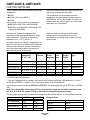
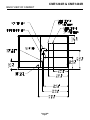
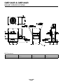
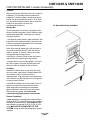
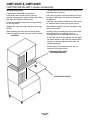
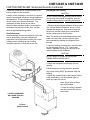
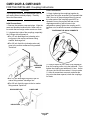
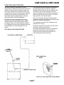
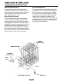
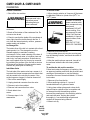
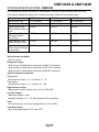
CME1202R & CME1402R INTRODUCTION To the owner or user: This service manual is intended to provide you and the maintenance or service technician with the information needed to install, start up, clean, maintain and service this ice system. Table of Contents FOR THE INSTALLER . . . . . . . . . . . . . . . . . . . . . . . . . . . . . . . . . . . . . . . page 2 BACK VIEW OF CABINET . . . . . . . . . . . . . . . . . . . . . . . . . . . . . . . . . . . . . page 3 ERC401 SPECIFICATIONS . . . . . . . . . . . . . . . . . . . . . . . . . . . . . . . . . . . page 4 FOR THE INSTALLER: Location & Assembly . . . . . . . . . . . . . . . . . . . . . . . . . . . page 5 FOR THE INSTALLER: Location & Assembly . . . . . . . . . . . . . . . . . . . . . . . . . . . page 6 FOR THE INSTALLER: Scotsman Remote Condenser . . . . . . . . . . . . . . . . . . . . . . page 7 FOR THE INSTALLER: Coupling Instructions . . . . . . . . . . . . . . . . . . . . . . . . . . . page 8 FOR THE ELECTRICIAN . . . . . . . . . . . . . . . . . . . . . . . . . . . . . . . . . . . . . page 9 FOR THE PLUMBER . . . . . . . . . . . . . . . . . . . . . . . . . . . . . . . . . . . . . . . . page 10 FINAL CHECK LIST . . . . . . . . . . . . . . . . . . . . . . . . . . . . . . . . . . . . . . . . page 11 INITIAL START UP . . . . . . . . . . . . . . . . . . . . . . . . . . . . . . . . . . . . . . . . . page 12 FREEZING CYCLE OPERATION . . . . . . . . . . . . . . . . . . . . . . . . . . . . . . . . . page 14 HARVEST CYCLE - HOT GAS BYPASS . . . . . . . . . . . . . . . . . . . . . . . . . . . . . page 15 COMPONENT DESCRIPTION . . . . . . . . . . . . . . . . . . . . . . . . . . . . . . . . . . . page 16 CLEANING . . . . . . . . . . . . . . . . . . . . . . . . . . . . . . . . . . . . . . . . . . . . . page 19 SYSTEM SPECIFICATIONS: CME1202 . . . . . . . . . . . . . . . . . . . . . . . . . . . . . . page 21 SYSTEM SPECIFICATIONS: CME1402 . . . . . . . . . . . . . . . . . . . . . . . . . . . . . . page 22 ADJUSTMENTS . . . . . . . . . . . . . . . . . . . . . . . . . . . . . . . . . . . . . . . . . . page 23 SERVICE DIAGNOSIS: Water . . . . . . . . . . . . . . . . . . . . . . . . . . . . . . . . . . . page 24 SERVICE DIAGNOSIS: Electrical and/or Adjustments . . . . . . . . . . . . . . . . . . . . . . page 25 SERVICE DIAGNOSIS: Refrigeration and/or Mechanical . . . . . . . . . . . . . . . . . . . . . page 26 SERVICE DIAGNOSIS: Bin Ice Level Control . . . . . . . . . . . . . . . . . . . . . . . . . . . page 27 REMOVAL AND REPLACEMENT . . . . . . . . . . . . . . . . . . . . . . . . . . . . . . . . . page 28 REFRIGERATION SERVICE . . . . . . . . . . . . . . . . . . . . . . . . . . . . . . . . . . . . page 31 LIQUID CHARGING . . . . . . . . . . . . . . . . . . . . . . . . . . . . . . . . . . . . . . . . page 32 Parts Lists and Wiring Diagrams are located in the center of this manual, printed on yellow paper. Note this symbol when it appears in the manual. It indicates a potential hazard. This manual was printed on recycled paper. Keep this manual for future reference. January 1995 Page 1 CME1202R & CME1402R FOR THE INSTALLER These machines will fit the following Scotsman ice storage bins: • BH900 • BH1000 (with bin top KBT21) • BH1360 A remote condenser and precharged tubing kit are required to assemble this ice system. The normal finish for the machine is enamel sandalwood. An optional stainless steel panel kit (SPKCMS48) can be field installed. It contains a stainless steel top, left side panel, an overlay right side panel, and front panels. and will stack onto the following ice machines: • CME1402 or CME1202 (use KSCMS48) • MCM1462 or CMS1402B or CMS1202B (with stacking kit KSCMS48) Scotsman reserves the right to make design changes and/or improvements at any time. Specifications and designs are subject to change without notice. Scotsman Ice Systems are designed and manufactured with the highest regard for safety and performance. They meet or exceed the standards of U.L., N.S.F., and C.U.L. Scotsman assumes no liability or responsibility of any kind for products manufactured by Scotsman that have been altered in any way, including the use of any parts and/or other components not specifically approved by Scotsman. Model Number Dimensions (without bin) W" x D" x H" CME1402RE-3A 48 x 243⁄8 x 271⁄2 208-230/60/3 15.5 20 336 oz. Remote Air CME1402RE-32A 48 x 243⁄8 x 271⁄2 208-230/60/1 22.9 30 336 oz. Remote Air 208-230/60/3 14.4 20 336 oz. Remote Air CME1202RE-32A 48 x 243⁄8 x 271⁄2 208-230/60/1 20.9 30 336 oz. Remote Air CME1202RE-3A CME1202RE-6A 48 x 243⁄8 243⁄8 x Basic Electrical 271⁄ 2 Minimum Maximum Refrigerant Condenser Circuit Fuse Charge** Type Ampacity* Size+ R-404A 271⁄ 336 oz. Remote Air 48 x x 2 230/50/1 * Minimum Circuit Ampacity is used to determine wire size and type per the National Electric Code. + Or HACR type circuit breakers. ** The unit is shipped with the charge in the receiver and, beginning with May 1996 production, 112 oz in the Scotsman ERC401 condenser. For re-charging purposes, see the table below. Use Scotsman remote condenser RCE1401 or ERC401. Use precharged tubing kit RTE25 (25’) or RTE40 (40"). Note: This refrigeration system may NOT be connected to a condenser circuit that had been used in a R-12, R-22 or R-502 system. Doing so will void the refrigeration system warranty. This ice system (except remote condenser) is designed to be installed indoors, in a controlled environment. Air Temperature Water Temperature Water Pressure Voltage MINIMUM MAXIMUM 500F. 400F. 20 psi -5% 1000F. 1000F. 80 psi +10% Charging Table Condenser Model ERC401 RCE1401 MAC 7G June 1996 Page 2 Total System Charge 448 oz 448 oz 336 oz CME1202R & CME1402R BACK VIEW OF CABINET June 1996 Page 3 CME1202R & CME1402R ERC401 SPECIFICATIONS 23 13⁄16" 19 7⁄8" ERC Dimensions A B F G 43 3⁄8" 10 3⁄4" 21 3⁄4" 16 5⁄8" June 1996 Page 4 CME1202R & CME1402R FOR THE INSTALLER: Location & Assembly Location: After uncrating and inspection, the unit is ready for installation. It is important that the machine be installed in a location where it has enough space around it to be accessible for service. Try to avoid hot, dirty and crowded locations. Be sure that the location for the machine is within the environmental limitations. ICE MACHINE AND BIN ASSEMBLY Storage Bin: Tip the storage bin on its back, using parts of the carton to protect the exterior finish. Install the legs packed with the BH900. If stacking use a heavy duty leg kit (KLP6). 1. Arrange for proper electric, water and drain. See instructions for the plumber and for the electrician. 2. After mounting the legs position the ice storage bin in the selected location: Note: Allow enough space to the left and back to service the machine. Do NOT push the bin into position, instead, lift it there. Pushing a bin may damage the legs and leg mounts. Level the bin in both the front to rear and side to side directions by adjusting the leg levelers. 3. Inspect the bin top mounting gasket. It must be flat, with no gaps, to provide a good water seal when the cuber is installed on top of the bin. Ice Maker: Install the modular cuber on top of the bin using care to be sure a good seal is made between the two cabinets. Use of a mechanical lift is recommended. Align the holes in the bottom rear of the cabinet to mate with the two mounting holes on the top rear of the bin. Use bolts and straps found on the back of the ice machine to secure the ice machine to the bin. When alignment and leveling are completed, tighten the bolts to secure the mounting straps. Remove the front panel, and remove the evaporator shipping brackets and hardware. Remote Condenser: A new condenser coil designed for the machine’s capacity MUST be used. Because of the possibility of mineral oil contamination, coils and line sets that had been connected to R-12, R-502 or R-22 units MAY NOT BE CONNECTED TO THIS SYSTEM. Doing so voids the refrigeration system warranty. June 1996 Page 5 SHIPPING BRACKETS CME1202R & CME1402R FOR THE INSTALLER: Location & Assembly Stacking Instructions A stacking kit, KSCMS48, is required to interconnect the ice level controls, seal the freezing compartments, support the bin with heavy duty legs, and retain the front panels. (The top removed from the lower ice maker will no longer have any function.) Add a strip of gasket (from the stacking kit) to the top edge of the bottom ice machines evaporator compartment. Follow the installation instructions of the stacking kit, but in general: Install the panel retaining bracket onto the bottom ice machine before placing the upper unit on it. Replace the original bin legs with heavy duty legs (KLP6). Place additional gasket onto the top edges of the bottom ice machine. When stacking two units, remove the top panel and the evaporator cover from the lower ice maker. Carefully lift the uncrated top unit onto the bottom one and align the two cabinets. Use of a mechanical lift is recommended for this step. STACKING At the back of the two ice makers, bolt the upper ice maker cabinet to the lower ice maker cabinet using the mounting straps and bolts from the hardware package. Add the relay kit to interconnect the two ice machine’s bin control circuits. STAINLESS STEEL PANEL RETAINING BRACKET EVAPORATOR COVER June 1996 Page 6 CME1202R & CME1402R FOR THE INSTALLER: Scotsman Remote Condenser Locate the condenser as near as possible to the interior location of the ice maker. Precharged Line Routing CAUTION Location of the condenser is limited by the specific length of precharged refrigerant tubing supplied for the application. The pre-charged tubing connects the ice maker to the remote condenser. The condenser must be above the ice maker. Do not connect precharged tubing until all routing and forming of the tubing is complete. See the coupling instructions for connecting instructions. 1. Each set of precharged refrigerant lines consists of a 3/8 inch diameter liquid line, and a 1/2 inch diameter discharge line. Both ends of each line have quick connect couplings, the end without access valves goes to the ice maker. Select the best available location, protecting the condenser from extremes of dirt, dust, and sun. Meet all applicable building codes. Roof Attachment: Install and attach the remote condenser unit to the roof of the building, using the methods and practices of construction that conform to the local building codes, including having a roofing contractor secure the condenser to the roof. Note: The openings in the building ceiling or wall, listed in the next step, are the minimum sizes recommended for passing the refrigerant lines through. 2. Have the roofing contractor cut a minimum hole for the refrigerant lines of 1.75". Check local codes, a separate hole may be required for the electrical power to the condenser. CAUTION DO NOT KINK OR CRIMP REFRIGERANT TUBING WHEN INSTALLING IT. 3. Route the refrigerant lines through the roof opening. REFRIGERANT CONNECTIONS Follow straight line routing whenever possible. Any excess tubing MUST be retained within the building. 4. Spiral any excess length of pre charged tubing inside the building. Use a horizontal spiral to avoid any traps in the lines. Note: Spiral need not be as tight as illustrated. 5. Have the roofing contractor seal the holes in the roof per local codes. LOCATE CONDENSER NO LOWER THAN ICE MACHINE TYPICAL INSTALLATION June 1996 Page 7 CME1202R & CME1402R FOR THE INSTALLER: Coupling Instructions Final Connections: CAUTION The couplings on the sets of precharged lines are self sealing when installed properly. Carefully follow the instructions: Initial Connections: 1. Remove the protector caps and plugs. Wipe the seats and threaded surfaces with a clean cloth to be certain that no foreign matter remains on them. 3. Begin tightening the couplings together by hand, then using two wrenches (it is important that ONLY the nut on the precharged lines be turned, the other parts of the couplings must NOT be allowed to turn or the process will tear out the diaphragms and they will be loose in the refrigeration system) tighten the coupling until it bottoms out or a definite increase in resistance is felt. TIGHTENING THE QUICK CONNECTS 2. Lubricate the inside of the couplings, especially the O-Rings with refrigerant oil. • The 1/2 inch discharge line (schrader valve end) goes to the remote condenser fitting marked “discharge line”. • The 3/8 inch liquid line (schrader valve end) goes to the remote condenser fitting marked “liquid line”. SCHRADER VALVES • The 1/2 inch discharge line goes to the ice 4. Using a marker or pen, mark a line lengthwise from the coupling union nut to the bulkhead. Then tighten the coupling and additional 1/4 turn. As the nut turns, the line will show when 1/4 turn is made. 5. After all connections are made, and after the king valve has been opened, check the couplings for leaks. maker fitting marked “discharge line”. • The 3/8 inch liquid line goes to the ice maker fitting marked “liquid line.” DISCHARGE LINE LIQUID LINE INSULATION June 1996 Page 8 CME1202R & CME1402R FOR THE ELECTRICIAN See the ice machine nameplate for current requirements to determine wire and fuse size to be used for electrical hookup. When the cuber and the remote condenser are connected, each must be grounded to the other using the ground screws provided in the respective junction boxes. The cuber then requires a solid chassis to chassis earth ground wire. See Wiring Diagram. Be certain the cuber is connected to its own electrical circuit and individually fused. Voltage variation should not exceed ten percent of the nameplate rating, even under starting conditions. Low voltages can cause erratic operation and may be responsible for serious damage to the ice maker. FOLLOW ALL APPLICABLE CODES The Scotsman remote condenser is designed to be powered from the ice machine. There is a separate electrical junction box at the back of the ice maker for the remote condenser. Wire the remote condenser to the ice maker in accordance with local and national electric codes. All outdoor wiring must be in rain proof conduit. Note: If connecting to another UL listed remote condenser, follow the instuctions provided with that product for electrical connections. The condenser fan motor will run whenever the compressor is running. Electrical connections are made at the rear of the ice maker, inside the junction box. All external wiring should conform to the national, state and local electrical code requirements. Usually an electrical permit and services of a licensed electrician will be required. ELECTRICAL CONNECTIONS HAND DISCONNECT SWITCH INTERCONNECTING WIRES POWER SUPPLY GROUND SCREW REMOTE CONNECTION DETAIL OF JUNCTION BOX, 3 PHASE SHOWN June 1996 Page 9 CME1202R & CME1402R FOR THE PLUMBER The recommended water supply line is a 3/8-inch O.D. copper tubing with a minimum operating pressure of 20 PSIG and a maximum of 80 PSIG. Connect to cold water supply line with standard plumbing fittings, with shut off valve installed in an accessible place between the water supply and the cuber. In some cases a plumber will be required. Water Limitations: An ice machine is a food manufacturing plant, it takes in a raw material, water, and turns it into a food product, ice. The purity of the water is very important in obtaining pure ice and in maximizing product life. It is generally better to filter the water, although there is no one filter that will cure all water problems. A good filter combined with a polyphosphate feeder gives about the best overall performance. POTABLE WATER SUPPLY DRAIN Connections: All drains are gravity type and must have a minimum of 1/4-inch fall per foot on horizontal runs. The drains to be installed to conform with the local plumbing code. Install a vertical open vent on drain line high point to insure good draining. The ideal drain receptacle is a trapped and vented floor drain. Recommended bin drain is 3/4 inch O.D. RIGID tubing and should be vented and run separately. Insulation for high humidity areas is recommended. The ice machine sump drain is 3/4" FPT. There must be a vent at this connection for proper sump draining. Recommended drain is 3/4 inch O.D. RIGID tubing and should be run separately. Insulation for high humidity areas is recommended. SUMP DRAIN MUST BE VENTED 3/4" FPT HAND SHUT OFF VALVE OPTIONAL FILTER 3/8" MALE FLARE VENT BIN DRAIN AIR GAP BETWEEN DRAIN LINES AND BUILDING DRAIN WATER SUPPLY AND DRAIN CONNECTION June 1996 Page 10 CME1202R & CME1402R FINAL CHECK LIST 1. Is the cabinet in a room where ambient temperatures are within the minimum and maximum temperatures specified? 2. Is there clearance at the left and back sides of the cabinet for service access? 3. Has water supply pressure been checked to insure a minimum of 20 PSIG and a maximum of 80 PSIG operating pressure? 4. Is the cabinet level? 5. Check that any shipping material has been removed from inside the cabinet. FINAL INSTALLATION 6. Check that the reservoir is properly secured to the bottom of the evaporator plates. 7. Have all electrical, water and drain connections been properly made? 8. Is the water supply line shut off valve installed and electrical wiring properly connected? 9. Check all refrigerant lines and conduit lines, to guard against vibration or rubbing and possible failure. PRECHARGED LINES CONNECTED 10. Have the bin and cabinet been wiped clean? 11. Has the Manufacturers Registration form been properly filled out? Check for correct model and serial numbers from Serial nameplate, then mail to the SCOTSMAN factory. 12. Has the owner/user been given the Service Manual and instructed how to operate and maintain the ice maker? LEVEL ASSEMBLY SUMP DRAIN HAND SHUT OFF VALVE 13. Has the owner been given the name and telephone number of the authorized SCOTSMAN Service Agency serving him? OPTIONAL FILTER BIN DRAIN June 1996 Page 11 CME1202R & CME1402R INITIAL START UP Before Start Up: FRONT VIEW OF TIMER 1. Check that both the ICE-OFF-WASH rocker switch and the COMPRESSOR ON-OFF toggle switch are in the OFF position. 2. Switch on the electrical power. Electrical power must be supplied to the ice machine for 4 hours before starting the compressor for the first time. The crankcase heater will now heat the compressor’s oil. The oil is warmed to evaporate any refrigerant that may have collected in it. If there is refrigerant in the oil when the compressor starts, the oil will foam and will not lubricate the compressor properly, shortening its life. ACTUATOR BUTTON MICROSWITCH CAM HARVEST PORTION Do NOT start the compressor for the first time unless the dome of the compressor is warm. Start Up 1. Remove front panels by removing screws at the base and pulling out. 2. Remove two screws and the control box cover. FREEZE PORTION 3. OPEN the water supply line shut off valve. 4. Open the “king” valve on the receiver. 5. Inside the control box is the shaft of the timer and switch assembly. Rotate the shaft of the timer clockwise until the actuator arm on the microswitch drops off outer cam into cam slot. See “Front View of Timer”. CONTROL BOX 6. Move the ICE-OFF-WASH to the ICE position. 7. Check the water fill cycle: For several minutes the inlet water valve will be open and water will flow into the reservoir. Near the end of the fill cycle water should be draining thru the reservoir drain. If at the end of the fill cycle the reservoir is not full, repeat step 5. Check that the sump covers are snapped in place. Check that the water distributors are properly seated at the top of the evaporators and that water is flowing over all cube cells. CUBE SIZE CONTROL Note: Some water spray from the evaporators is normal when the machine is new. The spray will quit after a few cycles. 8. When the sump has filled, move the compressor ON-OFF toggle switch, to the ON position. TIMER ICE/OFF/WASH BIN ICE LEVEL SWITCH June 1996 Page 12 CME1202R & CME1402R INITIAL START UP 9. Check operation of the freezing cycle: Ice will begin to form from the top of the evaporators down. After the first cycle, freezing time will range between 12 and 15 minutes. Longer time for temperatures above 70oF. and shorter time required when temperatures are below 70oF. Average complete cycle time is about 14 minutes. CUBE SIZE DIAGRAM JUST RIGHT 10. After an ice harvest, check Cube Size. There is just enough water available in the reservoir to make one full sized batch of cubes. As the water level drops, the water pump may pick up some air at the end of the freezing cycle so some bubbles in the pump discharge hose at the end of freeze is normal. If the water pump runs out of water before the end of freeze, the cube size control may be set too cold, or the water system may be leaking water. When the cubes are the correct size, they will be connected together vertically, and drop off in strips. The batch weight will be about 13.5 to 14.5 lb. Note: if the cubes at the bottom rows of some evaporators are smaller than others, the size difference does not affect capacity or performance. However, there should be ice in all cells. If not, contact the Factory. Compare cube size to the "Cube Size Diagram" TOO SMALL To adjust the cube size, locate cube size control in the front of the control box, and rotate the adjustment screw one eighth of a turn: • COUNTER Clockwise for SMALLER ice cubes • Clockwise for LARGER ice cubes CAMS Observe size of the ice in the next ice cube harvest and repeat adjustment until correct ice cube is achieved. ADJUSTMENT OF THE TIMER 11. Check Harvest Time. There must be enough time in harvest to defrost all the cubes but not an excessive amount that will waste capacity. The length of the harvest cycle is determined by the timer cam positions. SET SCREW If needed, adjust the harvest time so there are about 15 seconds of harvest time left after the last cube has fallen from the evaporators. Because harvest time varies with the water and air temperatures at the ice machine, colder air and water will result in faster ice making but require longer harvest cycles. Do NOT adjust harvest time too short or the unit will not harvest all the ice. The harvest time is set by: loosening the set screw on the cam, rotating the shaft to open or close the distance between the high part of the cams, and re tightening the set screw. More of an opening between the cams high areas=more harvest time. An adjustment of the cube size may be needed after the harvest time has been changed, so check the cube size again. 12. Check Bin Ice Level Control. When the unit is in the harvest cycle, place something solid against the transducer socket (located in the base to the left of the evaporators). The machine will switch off at the END OF THE HARVEST CYCLE, and will restart when the object is removed. The control has a Full and a Partial position. At Full, the machine will switch off when ice is 8" from the transducer socket. The control will not work on bins taller than 8’. Note: Even when full the unit will make a batch of ice if switched off and then on. 13. Replace all covers, panels and screws. 14. Fill out the Warranty Registration and Customer Evaluation form. Explain to the user the maintenance requirements of the ice machine. Inform the user of the name and telephone number of the local SCOTSMAN Distributor or service agency. June 1996 Page 13 CME1202R & CME1402R FREEZING CYCLE OPERATION Water from the sump assembly is pumped to the water distributor system at the top of each evaporator plate. From the water distributor the water cascades by gravity over all cells of the plate and to the sump assembly below. At the beginning of the freezing cycle, the electrical circuit is completed to the compressor and the water pump. The water pump operates continuously, through both the freezing cycle and the harvest cycle. Low Temperature Freeze: When the outside air temperature is low, the Head Pressure Regulator will close off the liquid line to the receiver, causing liquid refrigerant to back up into the condenser until the head pressure builds up to 240 PSIG. While this is occurring, the head pressure regulator passes discharge gas into the receiver to keep the refrigerant flowing. During the freezing cycle, the hot gas solenoid valve is CLOSED and the water inlet solenoid valve is CLOSED. When the ice cubes are partially formed, the cube size control will sense the temperature at which it is preset to CLOSE. This will complete the electrical circuit to the timer. The timer then controls the remainder of the freezing cycle. The timer will keep the ice maker operating in the freezing cycle for a selected length of time. This will give the ice cubes time to fully form. after that selected length of time, the timer will switch the ice maker into the harvest cycle, through the contacts of the timer assembly microswitch. WATER DISTRIBUTION INLET WATER VALVE DRAIN RESERVOIR WATER SCHEMATIC REFRIGERATION SCHEMATIC June 1996 Page 14 CME1202R & CME1402R HARVEST CYCLE - HOT GAS BYPASS When the timer switches the ice maker into the harvest cycle, high pressure, high temperature gas refrigerant being discharged from the compressor is diverted from the condenser through the hot gas solenoid valve into each evaporator plate. During this cycle, the refrigerant bypasses the condenser. In the electrical circuit, both the compressor and the water pump are operating and the hot gas solenoid valve is energized and OPEN and the water inlet solenoid valve is OPEN. Pump Down Cycle: When the ice level control is open at the end of the harvest cycle, power is removed from the liquid line valve coil, and the pump down cycle begins. The compressor will continue to run until the pump down control, sensing low side pressure, opens at 15 PSIG. The finished ice cubes are released from the sides of each evaporator plate by the warming effect of the hot gas condensing in each evaporator plate and the water cascading over the ice cubes. The released ice cubes drop into the ice storage bin below. At the end of the harvest cycle, the timer cam will push the actuator arm to the microswitch IN. If the ice level control is still CLOSED, a whole new cycle will begin. If the ice level control is OPEN, the ice maker will begin to shut OFF. WATER DISTRIBUTION INLET WATER VALVE RESERVOIR DRAIN WATER SCHEMATIC REFRIGERATION SCHEMATIC June 1996 Page 15 CME1202R & CME1402R COMPONENT DESCRIPTION Cube Size Control Timer - Timer & Switch Assembly This reverse acting thermostat controls the length of the freezing cycle. It is sensing the temperature of the suction line. When the suction line gets cold enough, the cube size control closes (on temperature fall) and starts the timer. A change in either ambient air or incoming water temperature will affect the efficiency of the refrigeration system, and this will vary the length of time it takes the evaporator to reach the temperature at which the cube size control is preset to close. See CUBE SIZE ADJUSTMENT BEFORE attempting to adjust the control. The function of the timer begins when activated by the cube size control. The outer surface, or large diameter lobe of the timer cam, determines the timer cycle for finish freezing of the ice cubes, while the inner surface, or small diameter lobe, determines the time cycle for the harvest cycle. Relay The multi-function, three pole, double throw, plug-in relay is installed directly into a receptacle on the printed circuit board in the control box. The relay functions in part to by-pass the bin thermostat control to prevent the ice maker from shutting OFF, when the bin thermostat opens during the freezing cycle. The bypass action serves to ensure full-sized ice cubes with each harvest cycle. When the microswitch button is pushed in there is power connected to the coil of the relay, and the unit is in the freeze cycle. When the microswitch button is released, the power to the relay is stopped, and the unit goes into harvest. The microswitch is actuated by a cam assembly directly connected to the timer motor. One complete rotation of the cam will take eight minutes. Harvest is preset at three and one half minutes, but is adjustable. High Pressure Safety Control This is a manual reset control that shuts down the ice maker, should the discharge pressure ever reach 450 PSIG. Located below the control box. Low Pressure Control (Pump Down) This pressure control connects power to the compressor contactor coil. Its Cut In is 35 PSIG and its Cut Out is 15 PSIG. Located below the control box. CONTROL BOX CUBE SIZE CONTROL RELAY TIMER & SWITCH Hi Pressure Reset, Push to Reset June 1996 Page 16 CME1202R & CME1402R COMPONENT DESCRIPTION Bin Level Control This electronic control uses sound waves to measure the distance between the bottom of the ice machine and the top of the ice in the bin. It is designed to control the machine’s ice production to maintain that distance. The control is adjustable so that the ice machine will maintain a certain height of ice. When set at FULL it will not allow the machine to fill the bin any closer to the ice machine than about 8", and it will not work if the distance to the bottom of the bin is greater than 8 feet. BIN ICE LEVEL SELECTOR SWITCH Because it uses sound waves, a slight “ticking” sound can be heard coming from the bottom of the machine. There are three parts to the control, the transducer, the circuit board, and the ice level control switch. ICE/OFF/WASH SWITCH THE USER CAN SELECT THE AMOUNT OF ICE TO BE MAINTAINED IN THE BIN. SOUND WAVES FULL PARTIAL June 1996 Page 17 CME1202R & CME1402R COMPONENT DESCRIPTION Water Inlet Solenoid Valve Hot Gas Solenoid Valve The water inlet solenoid valve fills the sump assembly with water and excess water overflows out the standpipe and down the drain. This action fills and rinses the sump during each harvest cycle. The flow rate is 1 g.p.m. The hot gas solenoid valve functions only during the harvest cycle, to divert the hot discharge gas from the compressor, by passing the condenser, for direct flow in the evaporator plates to release ice cubes from the ice cube molds. The hot gas solenoid valve is installed in a branch of the discharge line. When the harvest cycle begins the energized solenoid coil lifts the valve stem within the valve body, to cause the hot discharge gas to be diverted to the evaporators. Water Distribution System The water distribution system evenly supplies water to all cells of the evaporator plates. The water pump pumps water from the sump up the vertical tygon tube to the tee. From there water is channeled through the water manifold to the water distributors, above each evaporator plate, and from six holes within each distributor, water flows to the cells of each side of the evaporator plates. Gravity flow returns the unfrozen excess portion of water to the sump reservoir for recirculation. WATER DISTRIBUTORS SUMP STAND PIPE OPTIONAL WATER FILTER HAND VALVE SUMP PUMP COMPONENT LOCATION June 1996 Page 18 DRAIN CAP CME1202R & CME1402R CLEANING A Scotsman Ice System represents a sizable investment of time and money in any company’s business. In order to receive the best return for that investment, it MUST receive periodic maintenance. Maintenance and Cleaning should be scheduled at a minimum of twice per year. CLEANING: ICE MAKER 1. Remove screws and the front panel. 10. Move the ICE-OFF-WASH switch to the OFF (center) position. 2. Switch the compressor switch to OFF. Switch the ICE-OFF-WASH rocker switch to OFF. 11. Remove the cap and drain the cleaning solution from the sump. Replace the drain cap. 3. Remove the control box cover, and rotate the shaft of the timer and switch assembly CLOCKWISE advancing to the freezing cycle. (Beginning of the higher part of the cam against the microswitch). 12. Rotate the shaft of the timer and switch assembly CLOCKWISE to the harvest position (low part of the cam against microswitch). Move the ICE-OFF-WASH switch to the ICE position to start the Harvest cycle. 4. Open the ice storage bin door and discard all the ice. If after completing this procedure one or more evaporator plates does not have a full flow of water for each vertical column of cubes, shut down the operation and remove and clean all water distributor manifolds. Reinstall the water distributor manifolds. 5. Remove the hose clamp, rubber cap and drain all the water from the sump assembly into the bin. Replace the rubber cap and hose clamp. 6. Mix 24 ounces of Scotsman Ice Machine Cleaner with 2 gallons of warm (950F. - 1150F.) water. 7. Pour the cleaning solution into the reservoir until full. 8. Move the master switch to the WASH position. Note: The ice making portion of the water system should be sanitized after cleaning by repeating steps 2-12 and substituting a sanitizing solution for the cleaning solution. 13. Move the compressor switch to the ON position to start the ice making process. CAUTION 9. Let the unit operate for 30 minutes. During the wash cycle, if the machine runs out of solution, mix 2 more gallons of solution per step 6, refill the sump and continue the wash cycle for the remainder of the 30 minutes. Scotsman Ice Machine Cleaner contains acids. These compounds may cause burns. If swallowed, DO NOT induce vomiting. Give large amounts of water or milk. Call Physician immediately. In case of external contact, flush with water. KEEP OUT OF THE REACH OF CHILDREN. DO NOT use ice produced from the cleaning solution. Be sure none remains in the bin. 14. Check the next ice cube harvest to be certain that the ice cubes are clear and the acid taste is gone. 15. Add hot water to the bin to melt the ice. 16. Replace all panels. June 1996 Page 19 CME1202R & CME1402R CLEANING Remote Condenser To remove scale: 1. Shut off the ice machine. 1. Mix a cleaning solution of 4 ounces of Scotsman Ice Machine Cleaner to 4 pints of hot (950 F. to 1100F.) water. The fan blade can cause personal injury. Disconnect power before beginning to clean condenser. Scotsman Ice Machine Cleaner contains acids. These compounds may cause burns. If swallowed, DO NOT induce vomiting. Give large amounts of water or milk. Call Physician immediately. In case of external contact, flush with water. KEEP OUT OF THE REACH OF CHILDREN. 2. Remove dirt and debris that might be under the condenser. 3. Brush off the bottom of the condenser fins. Do not use a wire brush. 4. Check to see that the inside of the condenser is clean; light should be visible through the fins. If not, clean the internal parts by vacuum, pressure washer and/or coil cleaner. Ice Storage Bin The interior liner of the bin is in contact with a food grade product: ice. The storage bin must be cleaned regularly to maintain a sanitary environment. Once a week cleaning of the door & frame with soap and water, a hot water rinse and and air dry is a basic procedure. Scale that may form on the plastic liner of a bin may be removed by scrubbing the surface of the line with a mixture of Scotsman Ice Machine Cleaner and hot water. Remove any scale prior to sanitizing. Inlet Water Valve 2. Remove all ice from the bin. 3. Using rubber gloves, dip a nylon scouring pad into the cleaning solution, and scrub the scale off of the liner. 4. After the scale has been removed, rinse all of the surfaces inside the bin with clean, potable water. To sanitize the bin and ice machine: The inlet side of the water valve has a screen in it to protect the internal components from debris that may be carried to the valve by the water. If the screen becomes clogged, it must be cleaned off. Follow local codes for frequency of sanitizing. Use an approved sanitizer and follow the directions and warnings of that sanitizer or use the following instructions for use of household bleach, if it meets local codes: 1. Shut off the water supply. 1. Remove all ice from the bin. 2. Unplug electrical connector from the valve. 2. Mix a sanitizing solution of 1 ounce of household bleach to 2 gallons of water. 3. Dismount valve from cabinet. 3. Using clean rubber gloves and a clean cloth, wipe all interior surfaces of the ice machine and ice storage bin with the sanitizing solution. Immerse any small parts in the sanitizing solution and wash the parts, flushing the solution thoroughly in, over and through all parts and surfaces of the parts being cleaned. 4. Remove inlet connection from valve. 5. Brush debris from sceen. 6. Reverse steps 1-4 to reassemble. 4. Allow to air dry. SCREEN INLET WATER VALVE June 1996 Page 20 CME1202R & CME1402R SYSTEM SPECIFICATIONS: CME1202 The following numbers are a guideline to field operation There will be some variation from unit to unit. The numbers heading the columns are: Condenser air temp./Cabinet air temp./Water temp. Typical Cycle Time Standard Harvest Time* 0/70/55 16 - 17 minutes 90/90/70 17 - 18 minutes 110/90/80 19 - 20 minutes 3 1⁄2 minutes 3 1⁄2 minutes 3 1⁄2 minutes Typical Freeze Cycle 36 PSIG 35 PSIG Suction Pressure, End of Cycle Typical Freeze Cycle 250 PSIG 260 PSIG Discharge Pressure, End of Cycle 78 PSIG 100 PSIG Typical Harvest Cycle Suction Pressure, Peak Typical Air Cooled 140 PSIG 185 -190 PSIG Harvest Cycle Discharge Pressure, Min * See page 13 for harvest time optimization instructions. Typical Harvest Ice Weight • 13.5 to 14.5 lb. Refrigerant Charge: • 336 ounces of R-404A when connected to a MAC 7G condenser • 448 ounces of R-404A when connected to a RCE1401 condenser • 448 ounces of R-404A when connected to a ERC401 condenser. Typical Compressor Amp Draw Single phase • 5 minutes into freeze: 14 - 15 Harvest: 17 - 18 Three phase • 5 minutes into freeze: 8 - 9 Harvest: 10 - 10.8 High Pressure Cut Out • High pressure safety, Manual reset, cut out at 450 PSIG Ice Level Control • Maximum Range = 8 feet • Partial Fill Setting: = 21" - 22" from the base of the ice machine Timer • 1 revolution takes 10 minutes (changed from 8 in June 1996) Cube Size Control • Cut In adjustable between 0oF. and +250F. June 1996 Page 21 39 PSIG 305 PSIG 125 PSIG 225 PSIG CME1202R & CME1402R SYSTEM SPECIFICATIONS: CME1402 The following numbers are a guideline to field operation. There will be some variation from unit to unit. The numbers heading the columns are: Condenser air temp./Cabinet air temp./Water temp. Typical Cycle Time Standard Harvest Time* 0/70/55 15 - 17 minutes 90/90/70 16 - 17 minutes 110/90/80 18 - 19 minutes 3 1⁄2 minutes 3 1⁄2 minutes 3 1⁄2 minutes Typical Freeze Cycle 35 PSIG 31-35 PSIG Suction Pressure, End of Cycle Typical Freeze Cycle 265 PSIG 270 PSIG Discharge Pressure, End of Cycle 80 PSIG 90-95 PSIG Typical Harvest Cycle Suction Pressure, Peak Typical Air Cooled 155 PSIG 180- 200 PSIG Harvest Cycle Discharge Pressure, Min * See page 13 for harvest time optimization instructions. Typical Harvest Ice Weight • 13.5 to 14.5 lb. Refrigerant Charge: • 336 ounces of R-404A when connected to a MAC 7G condenser • 448 ounces of R-404A when connected to a RCE1401 condenser • 448 ounces of R-404A when connected to a ERC401 condenser. Typical Compressor Amp Draw Single phase • 5 minutes into freeze: 15 - 16 Harvest: 22 - 23 Three phase • 5 minutes into freeze: 9 - 10 Harvest: 13 - 14 High Pressure Cut Out • High pressure safety, Manual reset, cut out at 450 PSIG Ice Level Control • Maximum Range = 8 feet • Partial Fill Setting = 21" - 22" from the base of the ice machine Timer • 1 revolution takes 10 minutes (changed from 8 in June 1996) Cube Size Control • Cut In adjustable between 0oF. and +250F. June 1996 Page 22 36 PSIG 310 PSIG 110 PSIG 235 PSIG CME1202R & CME1402R ADJUSTMENTS MICROSWITCH Electrical power present in the control box can cause personal injury. Disconnect power before beginning to adjust timer. CLOSE UP VIEW OF TIMER SWITCH ACTUATOR CAM Adjustment Of The Timer & Switch Assembly One complete revolution of the cam on the timer takes eight minutes. The harvest time set at the factory is three and a half minutes. It. is important that the length of the harvest cycle allow enough time for all the ice cubes to fall from the evaporator. Too short of a time will cause the evaporator to freeze up and stop ejecting ice into the bin. Too much time wastes ice making capacity, energy and water. Adjustment of the harvest cycle may require a corresponding adjustment of the cube size control. Rotating the shaft of the timer cam clockwise will allow putting the machine into either the freezing cycle or harvest cycle, as required in the cleaning instructions. To Adjust The Timer & Switch Assembly: The length of the harvest cycle can be changed by loosening the set screw on the cam, and then rotating the shaft so that the opening between the cams change. More of an opening between the cams = more harvest time. The harvest time may be reduced if not needed. This will yield more ice per day. TIMER CAM ADJUSTING TIMER June 1996 Page 23 CME1202R & CME1402R SERVICE DIAGNOSIS: Water SYMPTOM No ice is made Cubes are not uniform in shape Long Freeze Cycle Makes thick ice/freezes up Cubes too large Low Capacity Unit runs out of water POSSIBLE CAUSE Inlet water valve will not open or is dirty No water being pumped over evaporators. Water inlet valve leaks thru at high rate Water distributors are dirty Inlet water valve leaks through See electrical/adjustment Water inlet valve restricted Low water pressure Sump covers out of position Inlet water valve leaks through See electrical/adjustment Incoming water very warm Lack of water Reservoir leaks Inlet water valve restricted Short harvest cycle Water pressure too low June 1996 Page 24 PROBABLE FIX Clean inlet screen, check coil, replace valve if required Check pump motor, replace pump if motor will not run. No water in reservoir, check inlet water valve, check reservoir for leak. Replace inlet water valve Clean water system Replace inlet water valve See electrical/adjustment Clean or replace valve Check water filter or supply Re-position sump covers Replace inlet water valve See electrical/adjustment Check water temperature to building See unit runs out of water Repair leak Clean or replace valve Adjust timer Check supply CME1202R & CME1402R SERVICE DIAGNOSIS: Electrical and/or Adjustments SYMPTOM Machine does not operate Makes thick ice/freezes up Runs, makes no ice Long freeze cycle Cubes too small Cubes too large Compressor cycles on and off on pump down control Compressor will not run Unit cycles on and off anytime in any cycle POSSIBLE CAUSE No power High pressure control open High temperature cut out open P. C. Board Open PROBABLE FIX Reconnect power Reset, check machine Hot gas valve leaks thru, replace Replace board Master switch open Timer contacts open Bin ice level control holding machine off Harvest Cycle too short Test/replace Replace timer See page 27 Adjust timer for longer harvest cycle Low water pressure Hot gas valve defective Sump covers out of position Cubes too small Check water filter or supply Replace hot gas valve Re-position sump covers Adjust cube size Cube size control stuck open Pump problem or water leak in reservoir Water inlet valve either lets in no water or leaks through Timer stuck Relay does not energize; unit stuck in harvest Water inlet valve leaks through Water temperature too high Cube size set wrong Cubes size control stuck closed Water inlet valve leaks through Replace cube size control Check water system and pump Replace inlet water valve Replace timer Replace relay Replace inlet water valve Advise user Adjust cube size Replace cube size control Replace inlet water valve and adjust cube size control Low refrigerant charge Locate leak, repair, replace drier, evacuate and weigh in nameplate charge. Liquid line valve or drier restricted Check and replace TXV restricted Check and replace Head pressure control valve not Check/replace head pressure working (low condensing temp.) control valve Low pressure control will not close Check pump down control for proper operation Contactor coil open Check/replace contactor Compressor windings open Check replace compressor Loose connection in PC board Replace PC board June 1996 Page 25 CME1202R & CME1402R SERVICE DIAGNOSIS: Refrigeration and/or Mechanical SYMPTOM Poor harvest Unit cycles off during freeze or harvest Low capacity POSSIBLE CAUSE Hot gas valve does not open PROBABLE FIX Check for power to the coil, check for not opening, replace Head pressure control valve does Replace head pressure control not maintain enough head valve. pressure. Hi temperature switch opens and Hot gas valve leaks thru, replace it closes High head pressure, from dirty condenser, faulty fan motor Non condensable gas in the system Extreme hot location Overcharge of refrigerant Hot gas valve leaks thru Unit shuts off before bin is full Compressor cycles on and off Liquid and discharge lines are in contact with each other Bin Ice level control is set to “Partial” Low pressure control opening and closing Compressor overheats Frost on compressor Some frost will not hurt TXV meters too much refrigerant June 1996 Page 26 Clean condenser, repair fan motor Purge system, evacuate and weigh in nameplate charge Relocate the cabinet Evacuate and weigh in nameplate charge At the end of the freeze cycle there should be frost on the evaporator end of the hot gas tubes, if not replace the hot gas valve Separate and insulate them Move bin Ice level rocker switch to “Full”. Check low side pressure, liquid line valve must open and low side pressure raise over 35 PSIG before pump down control will close to run compressor TXV not letting enough refrigerant into evaporators, adjust or replace TXV Mechanical fault with compressor, replace compressor Do nothing Replace TXV CME1202R & CME1402R SERVICE DIAGNOSIS: Bin Ice Level Control CONDITION DETERMINE CAUSE A. Listen for a ticking sound from Ice Machine does not run, it transducer. has power to it, the high pressure control is closed, the on/off switch is set to ON (the compressor will not operate until the liquid line valve opens, but the pump should be working if there is no ice in the bin). B. Remove front panel(s), twist transducer 1/4 turn and pull out. DO NOT UNPLUG with power connected. Examine the transducer, the inside must be clean and dry. C. Check power to bin level control board. D. Disconnect electrical power and test ice machine circuit by attaching a jumper wire between bin thermostat posts on circuit board part no. 12-1912-01 (the circuit board with the timer on it). Reconnect power. E. Transducer or ice level board assembly defective. Machine runs, makes ice, switches on and off, but ice level cannot be controlled. Indicator light is out or flickers, board may seem to be off PARTIAL VIEW OF CIRCUIT BOARD 12-1912-01 If the inside of the transducer (above screen) was wet, replace it. Set bin level to FULL and aim at an object about 1-3 feet away. Machine should restart, if not go to D. Should be 12 volts from transformer, if not replace transformer. If there is power go to D. If machine does not start go back to machine circuit. If machine starts, disconnect electrical power, remove jumper wire and reconnect electrical power. Then go to E. Replace transducer. Set bin level to FULL and aim at an object about 1-3 feet away. Machine should restart. If not, replace the board. Replace ice level switch Ice level switch may be defective. On boards with a light, check by moving switch & watching light. Check connection to ice level switch Repair or replace harness to switch PLUG - IN RELAY TIMER PROBABLE CORRECTION If no noise, go to C. If there is a noise, check for a light on the board (models built after 4/93). If there is a light on, check relay contacts N.O. and COM. The contacts should be CLOSED. If closed, go to D. If not, replace the board. If light is off, or prior model, go to B. Electrical Shock Hazard Can Cause Personal Injury. Disconnect Power Before Servicing. Bin Thermostat Posts at Line Voltage. BIN THERMOSTAT POSTS MENTIONED IN “B” ABOVE June 1996 Page 27 Sonar Sonar is Scotsman's ultrasonic device for measuring ice level and switching the ice machine on and off. It consists of a control board, transducer, level selector switch and transformer. Sonar Service Diagnosis Step 1. Determine if it's a bin control problem. – Machine will not switch on Reset high pressure cut out Jump the two posts on the circuit board marked "bin thermostat". If the machine starts, the sonar system needs to be checked out. – If the machine does not start, something else is wrong. Sonar Service Diagnosis Step 2: If it is a sonar problem, check the board. – 12 volts to board. If not, check the transformer. When ice is called for, the relay contacts are CLOSED. – Check the relay on the board. COM to NO should be closed. If they are open, REPLACE THE BOARD - NOT THE TRANSDUCER Sonar Service Diagnosis Step 3. If the red light is NOT ON – Check the selector switch and harness. Jump out the two outside pins on the board where the selector switch harness plugs on. The indicator light should come on and the machine should start. Sonar Service Diagnosis Step 4: If the red light is not on, and jumping the two outside pins does not work, check the transducer. – – CME1202 or CME1402: Twist and pull the transducer UP to remove it. CME865 and CME1002: Twist and pull the transducer DOWN to remove it. Sonar Service Diagnosis Transducer – – Check “Ticking” sound is normal Examine the screen and face of the transducer. If the screen is dirty, clean it. If the face of the transducer is wet, dry it and try it again. If the face of the transducer is wrinkled, replace the transducer - NOT THE BOARD. Sonar Service Diagnosis Transducer Check Switch power on and check the transducer against a hard, flat surface. Try a NEW transducer, if that does not fix the machine, replace the BOARD, but re-use the original transducer. – It is VERY UNLIKELY that BOTH the transducer and the BOARD have failed at the same time. Sonar Service Diagnosis Check Transducer Resistor (green and white wires) - should be about 260-270 ohms. CME1202R & CME1402R REMOVAL AND REPLACEMENT Cube Size Control To remove the cube size control: Electrical Shock Hazard. Electrical shock can cause personal injury. Disconnect power before beginning to service components. 1. Remove front panel. 2. Remove cover from control box. 3. Trace capillary tube, from the cube size control to the refrigerant suction line. NOTCH IN BACK OF CONTROL BOX Water Distributor Tubes And Manifold Tubes To remove the water distributor tube and manifold tube: 1. Remove the front panel. 2. Slide the water distributor tube to the front about 1/8-inch along the top of the evaporator plate, until the water distributor tube can be unsnapped from the flexible notch and lifted upward. WATER DISTRIBUTOR CUBE SIZE CONTROL REPLACEMENT OF THE CUBE SIZE CONTROL 4. Remove the coiled capillary tube bulb from the tube well on the suction line. 5. Remove electrical leads from the cube size control. 6. Remove screws and pull the capillary tube through the notch in the back of the control box. Remove the cube size control. To replace the cube size control, reverse the removal procedure. 3. Unsnap and disconnect water distributor tubes from the water manifold section. To replace the water distributor tubes and manifold tubes, reverse the removal procedure. BE SURE the notches in the water manifold tubes properly engage the alignment keys in the tee. BE SURE the water distributor tube is securely fastened at the notch at both sides of the evaporator plate. Check identical attachment for the left water distributor tube and notch; also, that the distributor/manifold connections at the top center of each evaporator plate is snug against the top of the plate. June 1996 Page 28 CME1202R & CME1402R REMOVAL AND REPLACEMENT Inlet Water Solenoid Valve Assembly To remove the inlet water solenoid valve assembly: Electrical Shock Hazard. Electrical shock can cause personal injury. Disconnect power before beginning to service components. 1. Shut OFF water supply to machine. 2. Loosen and remove outlet water line from the inlet water solenoid valve assembly. 3. Remove screws and pull the water solenoid valve out to gain access. INLET WATER VALVE Water Pump 1. Remove front panel. 2. Unplug water pump electrical connection. 3. Drain water reservoir. 4. Use corbin clamp pliers to loosen and slide corbin clamps on hoses away from pump. 5. Remove screws retaining pump to bracket. 6. Pull pump out of ice machine. 7. Reverse to reassemble. REMOVAL OF THE INLET WATER VALVE 8. Replace front panel. 8. Reconnect electrical power. Transducer 4. Pull electrical cord from solenoid coil terminals. 1. Disconnect electrical power BEFORE removing transducer. 5. Remove inlet water fitting from the water solenoid valve. To replace the inlet water valve assembly, reverse the removal procedures. 2. Remove the front panel and locate the transducer socket. Bin Ice Level Control Circuit Board 3. Twist inner portion of transducer counter-clockwise and push up gently. 1. Disconnect Electrical Power before removing circuit board. 4. Unplug transducer and remove from the machine. 2. Remove front panel. 5. Reverse steps 1-4 to reassemble. 3. Remove control box cover. 4. Remove wires from circuit board connections. 5. Unlock circuit board fasteners by twisting 1/2 turn. 6. Pull circuit board of off fastener posts. 7. Reverse to reassemble, refer to wiring diagram as needed. June 1996 Page 29 CME1202R & CME1402R REMOVAL AND REPLACEMENT Thermostatic Expansion Valve Hot Gas or Liquid Line Valve. 1. Before replacing this valve, be certain that the valve is the cause of the problem, and cannot be adjusted. 1. Before replacing this valve, be certain that the valve is the cause of the problem. 2. Remove the front panel. 3. Discharge and recover the refrigerant. 3. Discharge and recover the refrigerant. 4. Unplug the coil of the valve. 4. Locate the TXV bulb (on the suction line), remove the clamps and bulb from the tube. 5. With the refrigeration system open, unsweat the valve from the tubing. 5. With the refrigeration system open, unsweat the TXV from the tubing. 6. Place the new valve in position. 2. Remove the front panel. 6. Place the new TXV in position. 7. Wrap the new TXV body with heat sink material. Do not get any moisture in the valve. 8. Carefully braze the valve to the tubing. Examine the joints, if they look good proceed to the next step, if not, re-do them. 9. Install a new dryer, and braze it in place also. 10. Reattach the TXV bulb to the suction line in the same place as the old one. 11. Evacuate the system to 300 microns. 12. Weigh or measure the nameplate charge into the receiver. 13. If the machine has been off on the breaker there may be refrigerant trapped in the oil of the compressor, so do not restart until the compressor has been warmed by the crankcase heater for 4 hours. If the compressor was warm throughout the replacement process, the ice machine may be restarted without waiting to re-warm the compressor. 7. Wrap the new valve body with heat sink material. Do not get any moisture in the valve. 8. Carefully braze the valve to the tubing. Examine the joints, if they look good proceed to the next step, if not, re-do them. 9. Install a new dryer, and braze it in place also. 10. Plug the power cord back onto the coil. 11. Evacuate the system to 300 microns. 12. Weigh or measure the nameplate charge into the receiver. 13. If the machine has been off on the breaker there may be refrigerant trapped in the oil of the compressor, so do not restart until the compressor has been warmed by the crankcase heater for 4 hours. If the compressor was warm throughout the replacement process, the ice machine may be restarted without waiting to re-warm the compressor. June 1996 Page 30 CME1202R & CME1402R REFRIGERATION SERVICE This ice machine uses R-404A refrigerant and polyolester oil. Do NOT Pressure-Temperature Chart for R-404A use mineral oil in this refrigeration system. VAPOR VAPOR • R-404A is a "Near Azeotrope" so liquid charging is required: See the TEMP. PRESS. TEMP. PRESS. next page. • When the system is serviced, a special liquid line drier is required. It is (DEG F) (PSIG) DEG F) (PSIG) -20 17 70 146 included with replacement compressors. -18 18 72 150 • R-404A is not compatible with mineral oil, so these ice machines use 20 74 155 Polyolester oil. Polyolester oil absorbs water very easily. When one of -16 -14 21 76 161 these refrigeration systems is opened for service, it must be re-sealed -12 23 78 166 as soon as possible (15 minutes maximum). -10 24 80 171 • Special leak detection equipment is required to locate small refrigerant -8 26 82 177 leaks. Usually a leak detector capable of detecting a Halongenated -6 28 84 182 refrigerant or HFC-134A will work. Check with the leak detector -4 29 86 188 manufacturer if in doubt. -2 31 88 194 Access Valves: To use the access valves: 0 33 90 200 2 35 92 206 • Remove the cap from the stem, use a 3/16" allen wrench to check 4 37 94 212 that the valve is CLOSED. The remove the core cap. 6 39 96 219 • Close the valve and replace the caps when the job is finished. 8 41 98 225 The valve must be closed and the caps must be on or the valve 10 43 100 232 will leak. 12 46 102 239 General Information: 14 48 104 246 Work on the refrigeration system should only be done when it is certain 16 50 106 253 that the system needs repair. 18 53 108 260 20 55 110 268 • Refrain from checking refrigeration pressures without reason. 22 58 112 275 Visual inspection of the water system, observation of the ice 60 114 283 formation, amp draw, voltage, and other techniques will lead to proper 24 26 63 116 291 diagnosis. 28 66 118 299 • If gauges must be used, don’t always check the high side pressure. If 30 69 120 307 the condenser is clean and seems to be operating correctly, it most 32 72 122 316 likely is. 34 75 124 324 • If gauges must be used, use very short hoses to minimize refrigerant 36 78 126 333 discharged into the air. 38 81 128 342 • Refrigerant should not be added except as a way to determine the 40 85 130 351 proper operation of the product. If the system was low on refrigerant, 42 88 132 360 there is a leak, and it must be found and repaired. 44 91 134 370 46 95 136 379 • This system has a critical charge, it must be recharged with the 48 99 138 389 correct amount of refrigerant as listed on the nameplate of the ice 50 102 140 399 machine, or performance will suffer. 52 106 142 409 • Anytime the refrigeration system has been opened, the dryer should 54 110 144 420 be replaced. Note: Only a HFC type dryer can be used. 56 114 146 430 • When brazing the tubing connections to components such as the 58 118 148 441 TXV, the component must be protected by heat sink material. 60 123 150 452 Recover, reclaim or recycle refrigerant. The method chosen is up to 62 127 152 464 the service company. Any refrigerant placed into a Scotsman ice machine 64 132 154 475 must meet ARI spec 700-93. Reclaim programs are available through 66 136 156 487 most refrigerant wholesalers. 68 141 158 499 June 1996 Page 31 CME1202R & CME1402R LIQUID CHARGING Instructions for R-404A In preparation for charging, the low side hose should have a sight glass, and/or a restrictor device (such as a "Charge Faster") installed in it for metering liquid into the low side of the system. 1. After a thorough evacuation to at least 200 microns, shut off the manifold valves and switch off the vacuum pump. 2. Place a drum of R-404A onto an electronic scale. 3. Attach the charging hose to the drum. 4. Open the valve on the drum and purge the charging hose. 5. Zero out the scale. 6. Shut the low side access valve at the ice machine. 7. Open the discharge manifold valve full open. 8. Watch the scale, when the correct charge is shown, shut the manifold valve. Note: If all of the charge will not "go in" the discharge side: A. Shut the discharge access valve at the ice machine. B. Switch the machine on. C. Open the low side access valve at the ice machine. Hose Connection Schematic for Liquid Charging D. Open the low side manifold valve and observe the sight glass to be certain that only gas is flowing into the system. E. When the proper charge is indicated on the scale, shut off the manifold valve(s). Allen Wrench 9. Shut off the valve on the refrigerant drum. 10. Re-open the manifold valves until all liquid has flowed out of the hoses. 11. Shut the low side access valve on the ice machine. Torque Stem to 6-8 ft. lb. 12. Remove hoses from ice machine and replace Torque Stem Cap to 8-12 ft. lb. all caps. Torque Core Cap to 7-12 ft. lb. Access Valves Note: There are no valve cores in this valve. June 1996 Page 32