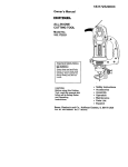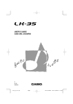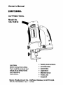
1
Owner's Manual
I:RRFTSMRN®
CUTTING TOOL
Model No.
183.172510
• Safety Instructions
• Accessories
CAUTION:
Before using this Cutting
Tool, read this manual and
follow all its Safety Rules
and Operating
Instructions,
•
•
•
•
•
Assembly
Operation
Maintenance
Parts List
Espanol
Sears, Roebuck and Co., Hoffman Estates, IL 60179 USA
Part. No, 183172510001
Rev, 1
11114/01
SECTION
PAGE
SECTION
PAGE
Warranty ........................................
Product Specifications ......................
Power Tool Safety ............................
Cutting Tool Safety ...........................
Electrical Requirements & Safety ........
Accessories ....................................
2
2
3
4
5
6
Carton Contents ..............................
Know Your Cutting Tool ....................
Assembly & Operation ......................
Maintenance ...................................
Repair Parts ...................................
Parts & Service Availability ................
6, 7
8
9 - 17
17
18 - 22
23
FULL ONE YEAR WARRANTY
If this Cutting Tool fails due to a defect in material or workmanship
purchase, Sears will at its option repair or replace it free of charge.
Return this Cutting
replacement.
Tool to a Sears
Service
Center
for repair,
within
one year of date of
or to place
of purchase
for
This warranty gives you specific legal rights, and you may also have other rights which may vary
from state to state.
Sears, Roebuck and Co., Dept. 817 WA, Hoffman Estates, IL 60179
IA WARNING I
:
Some dust created by power sanding, sawing, grinding, drilling and other construction activities contains
chemicals known (to the State of California) to cause cancer, birth defects or other reproductive harm. Some
examples of these chemicals are:
•
Lead from lead-based paints
•
Crystalline silica from bricks, cement and other masonry products
•
Arsenic and chromium from chemically treated lumber
Your risk from these exposures varies, depending on how often you do this type of work. To reduce your
exposure to these chemicals, work in a well ventilated area and work with approved safety equipment such as
those dust masks that are specially designed to filter out microscopic particles.
Motor Rating ......................
Amperes ...........................
Speed (no load) ..................
120V, 60Hz, AC
4.0 Amperes
30000 RPM
Motor Horsepower ......
Weight .....................
113HP (Maximum Developed)
3.75 kg
IA WARNING I
To avoid electrical hazards, fire hazards or damage to the spiral cutter, use proper circuit protection.
This cutting tool is wired at the factory for 110-120 Volt operation. It must be connected to a 110-120 Volt 115
Ampere time delay fuse or curcuit breaker. To avoid shock or fire, replace power cord immediately if it is worn, cut
or damaged in any way.
Before using your cutting tool, it is critical that you read and understand these safety rules. Failure to follow these
rules could result in serious injury to you or damage to the cutting tool.
2
IA WARNINGJ
Before using your cutting tool, it is critical that you read and understand these safety rules.
Failure to follow these rules could result in serious injury to you or damage to the cutting tool.
15. REMOVE ADJUSTING KEYS AND WRENCHES.
Form the habit of checking to see that keys and
adjusting wrenches are removed from the tool before
turning "ON".
Good safety practices are a combination of common
sense, staying alert and understanding how to use your
power tool. To avoid mistakes that could cause serious
injury, do not plug in your cutting tool until you have read
and understood the following safety rules:
1.
16. NEVER LEAVE TOOL RUNNING UNATTENDED.
TURN THE POWER "OFF". Do not leave the tool
before it comes to a complete stop.
READ and become familiar with this entire Owner's
Manual. LEARN the tool's applications, limitations and
possible hazards.
17. NEVER STAND ON TOOL. Serious injury could
occur if the tool is tipped or if the cutting tool is
unintentionally contacted.
2. IA WARNING I
Lock for this symbol that identifies important safety
precautions. It means CAUTION! BECOME ALERT!
YOUR SAFETY IS INVOLVEDI
.
18. DO NOT OVER REACH.
balance at all times.
19. MAINTAIN TOOLS WITH CARE. Keep tools sharp
and clean for most efficient and safest performance.
Follow instructions for lubricating and changing
accessones.
KEEP GUARDS IN PLACE and in working order.
4.
DO NOT USE IN A DANGEROUS ENVIRONMENT
such as damp or wet locations or exposure to rain.
Keep work area well lighted.
5.
DO NOT use power tools in the presence of
flammable liquids or gases.
6.
KEEP WORK AREA CLEAN. Cluttered areas and
workbenches invite accidents.
7.
KEEP CHILDREN AWAY. All visitors should be kept
at a safe distance from the work area.
8.
DO NOT FORCE THE TOOL. It will do the job better
and safer at the rate for which it was designed.
9.
USE THE RIGHT TOOL. Do not force the tool or
attachment to do a job for which it is not designed.
Keep proper footing and
20. CHECK FOR DAMAGED PARTS. Before further use
of the tool, a guard or other part that is damaged
should be carefully checked to ensure it will operate
properly and perform its intended function. Check for
alignment of moving parts, binding of moving parts,
mounting and any other conditions that may affect its
safe operation. A guard or other part that is damaged
should be properly repaired or replaced.
21. MAKE WORKSHOP CHILD PROOF with padlocks,
master switches or by removing starter keys.
22. DO NOT operate the tool if you are under the
influence of any drugs, alcohol or medication that
could impair your ability to use the to01 safely.
10. WEAR PROPER APPAREL. DO NOT wear loose
clothing, gloves, neckties, rings, bracelets or other
jewelry that may get caught in moving parts. Non-slip
footwear is recommended. Wear protective hair
covering to contain long hair.
23. USE DUST COLLECTION SYSTEM wherever
possible. Dust generated from certain materials can
be hazardous to your health and in some cases, a fire
hazard. Always operate the power tool in a well
ventilated area with adequate dust removal.
11. WEAR A FACE MASK OR DUST MASK. Sawing,
cutting, drilling and sanding operations produce
hazardous dust.
24. ALWAYS WEAR EYE PROTECTION.
Any power
your eyes which could cause
permanent eye damage. ALWAYS
tool can throw foreign objects into
wear safety goggles (not glasses)
that comply with ANSI safety
standard Z87.1. Everyday glasses have only impact
resistant lenses. They ARE NOT safety glasses.
Safety goggles are available at Sears.
12. DISCONNECT TOOLS FROM THE POWER
SOURCE before servicing and when changing
accessories such as blades, bits, cutters, etc.
13. REDUCE THE RISK OF UNINTENTIONAL
STARTING. Make sure the switch is in the "OFF"
position before plugging into the power source.
IA WARNING
I
14. USE ONLY RECOMMENDED ACCESSORIES.
Consult the Owner's Manual for recommended
accessories. The use of improper accessories may
cause injury to you or damage to the tool.
Glasses or goggles not in compliance with ANSI
Z87.1 could cause serious injury when they break.
SAVETHESEINSTRUCTIONS
3
FOR REFERENCE
IA
WARNING]
For your safety, do not plug in your cutting tool or try
to use any accessory until it is completely assembled
and installed according to these instructions, and
until you have read and understood this Owner's
Manual.
11. NEVER HOLD THE WORKPIECE IN ONE HAND
while operating the tool with the other hand.
Failure to follow these safety rules will result in risk of
serious injury,
13. NEVER START THE TOOL WHEN THE BIT IS
TOUCHING THE WORKPIECE. The bit may catch
the workpiece causing loss of control.
1.
2.
3.
,
.
6.
.
.
12, NEVER PLACE HANDS IN THE PATH OF THE
CUTTER AND UNDER THE WORKPIECE.
WEAR EYE PROTECTION. This high speed tool will
throw particles from the workpiece during operation,
Make sure safety glasses have side shields.
14. ALWAYS HOLD THE TOOL WITH TWO HANDS
DURING START-UP AND OPERATION. When
starting, motor torque will cause the tool to twist.
USE FACE OR DUST MASK along with safety
goggles if cutting or routing operation is dusty. Make
sure work area is well ventilated,
USE HEARING PROTECTION,
extended periods of operation.
15. TURN OFF ALL CIRCUIT BREAKERS AND
REMOVE ALL FUSES in the work area when cutting
into walls or blind areas,
particularly during
16, ALWAYS HOLD THE TOOL BYTHE INSULATED
GRIPPING SURFACES ON THE BODY OF THE
NEVER USE DULL OR DAMAGED BITS. Damaged
bits can break without warning. Dull bits may
overload the motor, cut slowly and are difficult to
control. They will also overheat and possibly break.
TOOL where there is any possibility of the cutting bit
contacting hidden electrical wires or the cord of the
tool, Contact with "live" wires will make exposed
metal parts of the tool "live" causing an electrical
shock to the operator.
ALWAYS MAKE SURE THE WORKPIECE IS FREE
OF NAILS AND OTHER FOREIGN OBJECTS, If the
bit strikes a nail it will jump sideways and possibly
break,
17. WHEN CUTTING DRYWALL ELECTRICAL OUTLET
OPENINGS using the outlet as a guide, always cut in
a counter clockwise direction. The natural tendency
of the tool to pull to the left will cause a "hugging"
action toward the outlet box, resulting in a neater cut.
DO NOT USE THIS TOOL FOR DRILLING HOLES.
It is NOT intended to be used as a drill.
18. NEVER LAY THE TOOL DOWN UNTIL THE
CUTTING BIT COMES TO A COMPLETE STOP. A
spinning bit can come in contact with the surface and
pull it out of your control.
ALLOW CLEARANCE UNDER WORKPIECE for bit
to travel. Never place workpiece on hard surfaces
such as concrete etc. The bit may jump or break
when contacting a surface other than the one being
cut.
19. NEVER TOUCH THE CUTTING BIT IMMEDIATELY
AFTER USE. The bit will be too hot to be handled
with bare hands and will burn your fingers.
ALWAYS SET THE DEPTH GUIDE TO THE
APPROPRIATE DEPTH. Use tool with the depth
guide fiat against the work surface for better control of
the tool.
9,
20. ALWAYS RE-TIGHTEN COLLET AND ALL
ADJUSTMENTS before starting the tool after a cutting
bit or accessory has been changed. Loose bits and
adjustments can cause unexpected shifting of the tool,
resulting in loss of control and injury from the bit or
cutting tool being thrown.
NEVER USE THE TOOL WITHOUT THE SOLE
PLATE, PRECISION HANDLE OR ROUTER BASE
attached and appropriately adjusted.
10. ALWAYS CLAMP WORKPIECE TO HOLD IT
STEADYWHEN CUTTING. This will free both hands
for operating the tool,
SAVE THESE INSTRUCTIONS
4
FOR REFERENCE
DIo]Ill :t Ill=Ill _l_-tnllW:lllll[o] _
[€llJla] =111_1:1."]I;[e] =_I::):t 1:1_ _.1[el _[e(e] t._e]._!
Make sure your extension cord is in good condition.
When using an extension cord, be sure to use one heavy
enough to carry the current the tool will draw. An
undersized cord will cause a drop in line voltage resulting
in loss of power and overheating. The table below shows
the correct size to use according to cord length and
nameplate ampere rating. If in doubt, use the next heavier
gauge. The smaller the gauge number the heavier the
cord.
This cutting tool is double insulated to protect you from
electrical shock.
IA WARNING
I
Double insulated tools are equipped with a polarized
plug (one blade is wider than the other). This plug will
fit into a polarized outlet only one way. If the plug
does not fit fully into the outlet, reverse the plug. If it
still does not fit, contact a qualified electrician to
install a polarized outlet. Do not alter the plug in any
way. Double insulation eliminates the need for the three
wire grounded power cord and grounded power supply
system.
Be sure your extension cord is properly wired and in
good condition. Always replace a damaged extension
cord or have it repaired by a qualified electrician before
using it. Protect your extension cord from sharp objects,
excessive heat and damp or wet areas.
Avoid body contact with grounded surfaces such as
pipes, radiators, ranges and refrigerators.
There is an
increased risk of electric shock if your body is grounded.
Use a separate electrical circuit for your power tools.
This circuit must not be less than 14 gauge wire and
should be protected with either a 15 Ampere time delay
fuse or circuit breaker. Before connecting the power tool
to the power source, make sure the switch is in the OFF
position and the power source is the same as indicated on
the nameplate. Running at lower voltage will damage the
motor.
Do not expose power tools to rain or wet conditions.
Water entering a power tool will increase the risk of
electric shock.
Do not abuse the cord. Never use the cord to carry
the tool or pull the plug from the outlet. Keep cord
away from heat, oil, sharp edges and moving parts.
Replace damaged cords immediately. Damaged cords
increase the risk of electric shock.
IA
WARNINGJ
Repair or replace damaged or worn extension cords
immediately.
When operating a power tool outdoors, use an
outdoor extension cord marked "W-A" or "W". These
cords are rated for outdoor use and reduce the risk of
electric shock.
Select the appropriate extension cord gauge and length
using the chart below.
MINIMUM GAUGE (AWG) EXTENSION CORDS
(120 Volt use only)
Ampe_ Rating
Total length in _et
Not
More Than
More Than
25'
50'
100'
150'
0
6
18
16
16
14
6
10
18
16
14
12
10
12
16
16
14
12
12
16
14
12
N_Appli_ble
IA WARNING
I
Always make sure the receptacle is polarized. If you
are not sure, have a qualified electrician check the
receptacle,
[,AwAR.,.G]
Keep the extension cord clear of the working area.
Position the cord so it will not get caught on the
workpiece, tools or any other obstructions while you
are working with the power tool.
5
r:Io_e]::_"!,._
AVAILABLE
[A
ACCESSORIES
UNPACKING AND CHECKING
WARNING]
[,A WARNING
CARTON CONTENTS
I
Use only accessories recommended for this cutting
tool. Follow instructions that accompany
accessories. Use of improper accessories may cause
injury to the operator or damage to the cutting tool.
If any part is missing or damaged, do not plug the
cutting tool into the power source until the missing or
damaged part is replaced and assembly is complete.
Visit your Sears Hardware Department or see the Sears
Power and Hand Tool Catalog for an assortment of
accessories recommended for use with this cutting tool:
Carefully unpack the cutting tool and all its parts.
Compare against the "Cutting Tool Components" chart
below.
NOTE: See Page 7 for illustration of parts.
•
•
IA WARNING I
•
1/8"Cutting Bits
118"Hobby Rotary Tool Accessories
Cutters
Polishers
;_ Sanders
Grinders
Most ¼" Shank Router Bits
To avoid fire or toxic reaction, never use gasoline,
naphtha, acetone, lacquer thinner or similar highly
volatile solvents to clean the cutting tool.
CUTTING
KEY
A
B
C
D
E
IA WARNING I
Use only accessories designed for this cutting tool to
avoid severe injury or tool damage.
Do not use any accessory unless you have completely
read the instructions or Owner's Manual for that
accessory.
F
G
H
I
J
K
L
M
6
TOOL
COMPONENTS
DESCRIPTION
Cutting Tool
Precision Handle with Sole Plate
Freehand Sole Plate Attachment
Circle Cutter Attachment (Optional)
Circle Cutter Installation Adapter
(Part of Circle Cutter attachment)
Router Base Attachment (Optional)
1/8" Collet Sleeve
1/4" Collet Sleeve
Lateral Style Drywall Cutter
Collet Wrench
Collet Wrench Holder
Owner's Manual
Carrying Case
QTY
1
1
1
1
1
1
1
1
1
1
1
1
I
A
G
H
L
B
__
E
M
C
D
j
K
Items D, E and F are optional attachments and must
NOTE:
be
purchased separately
I
NOTE: Optional Circle Cutting
Attachment Sold Separately.
©
Motor
Housing
Locking
Knob
Motor
Housing
Locking
Knob
Mounting
Bracket
Mounting
Bracket
Circle
Knob
Mounting
Insert
PivotPoint
Knob
Sole Plate
- Mounting
Disc
Motor
Housing
Adjusting Knobs
Locking
Knob
Locking
Knob
Precision
Handle
Bevel
Knobs
Router
Base
Sole
Plate
I Attachment
NOTE: Optional
Sold Router
Separately.
Base
8
[A, WARNING]
Remove the plug from the power
assembly, changing accessories
making adjustments. This safety
prevent accidental starting of the
result in serious injury.
source before
or cutters and
action will help
tool which could
INSTALLING CUTTING BITS - cont'd
.
Insert new cutting bit (4) into the collet.
[_,
WARNING
I
Insert the bit all the way into the collet and then
pull it back between 1/16"and 1/s'. This creates an
air space between the motor shaft and the bit to
help prevent overheating the bit.
ON / OFF SWITCH
This cutting tool is equipped with a sliding ON / OFF
switch (1) located on the side of the tool (see Fig 1)
Before tightening the collet on the bit, make sure
the flutes (spiral portion) of the bit are completely
visible outside the collet. Clamping the collet on
the bit flutes will result in broken bits and possible
injury.
.
6.
When bit is properly placed in the collet, depress the
shaft locking button and turn the coilet nut clockwise
by hand as far as possible.
Securely tighten collet nut using the wrench.
Fig. 1
1.
To turn the tool ON, slide the switch up.
2.
To turn the tool OFF, slide the switch down.
INSTALLING
CUTTING BITS
WARNING I
Cutting bit and router bit cutting surfaces are
extremely sharp. Handle with caution.
4
2
To insert a cutting bit, use the collet wrench which is in the
wrench holder attached to the power cord.
.
Depress the shaft locking button (1) and rotate the
collet lock nut (2) clockwise with the other hand until
the locking button drops into place, preventing the
shaft from turning (see Fig. 2).
2.
While continuing to hold the shaft locking button IN,
use the collet wrench (3) to turn the collet nut counter
clockwise. Loosen the collet nut 2 or three turns.
3.
Remove bit if one is already installed in the tool.
Fig. 2
9
CHANGING COLLET INSERT
INSTALLING FREEHAND SOLE PLATE - cont'd
The cutting bits for this tool are locked into place with a
collet nut (1) and collet (see Fig. 3). The tool is
assembled at the factory with a 1/8"collet (2) which is used
to hold the cutting bit. An additional ¼" collet (3) is
supplied for holding SMALL router bits with a ¼" shank.
.
2
,
Remove accessory locking knob (_i) from the base of
the cutting tool motor housing (see Fig. 4). Slide
freehand sole plate mounting bracket (2) onto the
bottom of motor housing (3) until the mounting hole
(4) lines up with the hole in the motor housing.
NOTE: The tab on the side of the sole plate mounting
band must be inserted into the matching slot in the
motor housing.
Re-insert accessory locking knob into the motor
housing and securely tighten.
3
Fig. 3
To change from one collet size to the other:
1.
Remove bit from the tool.
2.
Continue turning the toilet nut counter clockwise until
it can be removed from the motor shaft (4).
.
Pull the collet out of the motor shaft and replace it with
the other one.
NOTE: Each collet is the same on both ends, so either
end can be inserted into the motor shaft.
4.
Re-install the collet nut and slightly tighten it by hand.
5.
Install the new bit as outlined in INSTALLING
CUTTING BITS on Page 9.
Fig. 4
ADJUSTING FREEHAND SOLE PLATE
.
NOTE: Tightening the collet nut without a bit in the collet
will cause the collet hole to become smaller and make
installing bits difficult. When storing the tool with no bit
installed, leave collet nut loose.
;1='|=1=1:r_'l_ll] k._,o]III=1I'J IF-II I
INSTALLING
FREEHAND SOLE PLATE
The freehand sole plate is designed for basic freehand
cutting with the cutting bit. It is ideally suited for cutting
electrical outlet holes in drywall
Adjust freehand sole plate depth by loosening the
depth gauge knob (5) and sliding the sole plate (6) in
or out as required (see Fig. 5).
NOTE: Set the depth gauge so the cutting bit
protrudes beyond the sole plate lie" more than the
thickness of the material being cut. For example, if
you are cutting 518"drywall, the bit should protrude %"
beyond the sole plate.
2.
Securely tighten depth gauge knob.
3,
Before starting to cut you should re-check bit depth,
make sure sole plate is at right angles to the bit and
securely tightened. Re-check the collet to make sure
the bit is securely fastened.
[A WARNING I
Do NOT use the freehand sole plate with router bits.
Limited control with this accessory could cause you
to loose control and increase the chance of serious
injuy,
lO
Fig. 5
PRACTICE CUTS USING FREEHAND SOLE PLATE
IA WARNING
I
Have you read "POWER TOOL SAFETY",
"CUTTING TOOL SAFETY" and "ELECTRICAL
SAFETY" on pages 3, 4 and 5 of this Manual?
not, please do it now before you operate this
curing tool. Your safety depends on itl
6.
Turn the switch ON.
When the motor is up to full speed, slowly tip the tool
to an upright position, letting the bit cut into the
workpiece (see Fig. 7). Once the tool has reached the
upright position and the bit has cut through the
workpiece, slowly move the tool in a clockwise
direction using slow steady pressure to make the cut.
NOTE: Except for cutting around outlet boxes in
drywall, always cut in a clockwise direction.
,
If
Every time you use the curing tool you should
verity the following:
1. CuRing tool cord is not damaged.
2. Bit is correct type for the material being cut.
3. Bit is sharp, in good condition, properly
installed and securely tightened.
4. Safety glasses and dust mask are being worn.
8.
When cut is complete, turn the tool OFF, wait until it
comes to a complete stop and remove it from the
workpiece.
Failure to adhere to these safety rules can greatly
increase your chances of injury.
!
PRACTICE CUTS USING FREEHAND SOLE PLATE
Before attempting to work on an actual project, take the
time to make a few practice cuts with your cutting tool.
Use some scraps of material that are the same material as
used in your actual project.
1.
Draw a pattern similar to your first project on a scrap
piece of material.
Fig. 7
2.
Install freehand sole plate as shown in Fig. 4.
IA
3.
Install cutting bit in the collet as shown in Fig. 2.
Do not attempt curing around outlet boxes in drywall
until:
4.
Adjust depth of freehand sole plate as shown in Fig. 5.
,
Rest the edge of the sole plate on the workpiece with
the bit at an angle of about 45 ° (see Fig. 6).
NOTE: DO NOT let the bit contact the workpiece until
switch is turned ON and the tool is up to full speed.
[A
WARNING]
DANGER
]
1.
All electricity in the vicinity of electric wires has
been disconnected by either turning the breaker
OFF or removing the fuses.
2.
You have read the instructions on the following
page entitled "CUTTING OUTLET OPENINGS IN
DRYWALL".
CUTTING TIPS
Before turning the tool switch ON, make sure you
hold the tool firmly with both hands. Starting
torque will cause the tool to twist.
The rotating cutting action of the bit will cause a slight pull
to the left when cutting. Natural variations in the structure
of wood will cause the bit to "wander". This tendency will
be magnified when applying too much pressure to the bit.
Slower cutting gives you better control. Excessive
pressure or fast cutting will increase bit temperature and
shorten the life of the bit.
When cutting a hole in a vertical surface, avoid ending the
cut at the bottom of the hole. Always start and end the cut
at the "top" so the cut-out part will not drop onto the
rotating bit. Always turn the tool OFF before removing it
from the workpiece.
Fig. 6
11
CUTTING OUTLET OPENINGS IN DRYWALL
IA
DANGER
CUTTING OUTLET OPENINGS IN DRYWALL - cont'd
I
Do not attempt to use this tool to make cut-outs
around any fixture or opening which has live electrical
wires or on any wall which may have electrical wiring
behind it. If a live wire is contacted, the bit could
conduct the electric current to the tool, creating an
electrocution hazard for the operator. Turn OFF
breakers or remove fuses to disconnect the electric
circuit in the area of work. Always hold the tool by its
insulated housing when working in areas where there
is a possibility of contacting electric wires. Always
wear eye protection when operating this tool.
6.
Move the bit slowly to the right until you feel and hear
the bit contacting the inside of the box.
7.
Pull the bit out far enough to slip it over the edge of
the box. Once the bit is outside the box, push it back
to full depth beside the outside edge of he box.
,
g,
1.
,
Before installing drywall, push the electrical wires to
the back of the box as far as possible so they will not
be cut by the bit when cutting the opening.
Before fastening the drywall sheet over the electrical
box, mark the sheet as close as possible to the center
of the box opening. Mark should be on the side of the
drywall facing you.
,
When fastening the drywall in place, do not place nails
or screws closer than 12" from the box. This will
prevent the drywall from becoming deformed under
pressure.
,
Insert cutting bit and install freehand sole plate as
outlined on Pages 9 & 10 of this Owner's Manual.
Adjust dept of cut so the bit will protrude 118"beyond
the thickness of the drywall.
.
Move the tool upward while applying slight pressure
toward the center of the box. When you feel the bit
reach the top right hand corner of the box, move the
tool to the left while applying slight pressure
downward toward the center of the box.
Continue moving the tool around the box in a counter
clockwise direction while maintaining slight pressure
toward the center of the box. When the box cut-out is
complete. Turn the tool OFF and remove it from the
cut-out.
10. Completed electrical box cut-out will be accurately
and neatly cut (see Fig. 9).
\
Hold the tool firmly with both hands and turn it ON.
Plunge the bit through the drywall at the mark
indicating the center of the box. See Fig. 8 for cutting
pattern.
Fig. 9
NOTE: Always move the cutting bit in a counter
clocl_Niee direction around the outlet box. The natural
tendency of the cutting bit to move to the left will make it
easier to cut close to the box,
Fig. 8
12
ADJUSTING FREEHAND SOLE PLATE - Cont'd
I"J_ =[_[_[o]_IIV:I_Ie]I:
INSTALLING
PRECISION HANDLE
The precision handle is designed for use when precision
control over the tool movement is desired. The
comfortable handle can be used with either the right or left
hand.
.
2.
Remove accessory locking knob (1) from the base of
the cutting tool motor housing (see Fig. 10). Slide
precision handle mounting bracket (2) onto the bottom
of motor housing (3) until the mounting hole (4) lines
up with the hole in the motor housing.
NOTE: The tab on the side of the precision handle
mounting bracket must be inserted into the matching
slot in the motor housing.
NOTE: Optional Circle Cutting
Attachment Sold Separately.
INSTALLING CIRCLE CUTTER
The circle cutter accessory is ideal for precision cutting of
circles. This circle cutter can be attached to either the
freehand sole plate orthe precision handle sole plate. For
purposes of illustration, the circle cutter is shown with the
freehand sole plate.
Re-insert accessory locking knob into the motor
housing and securely tighten.
.
2.
.
Place circle cutter mounting hole (3) over the
externally threaded circle cutter mounting insert.
NOTE: Make sure pointed pivot pin (4) is pointing
away from the tool.
.
Screw the internally threaded circle cutter mounting
disc (5) onto the externally threaded circle cutter
mounting insert and hand tighten.
NOTE: Do not over tighten the circle cutter mounting
plastic parts. Hand tighten only.
.
Adjust the circle cutting radius by loosening pivot point
knob (6), sliding it to the correct circle radius and retightening in the desired location.
NOTE: Check circle cutter radius setting by measuring
from the pivot point to the outside of the cutting bit.
.
3.
SOLE PLATE
Adjust precision handle sole plate depth, by loosening
the depth gauge knob (5) and sliding the sole plate (6)
in or out as required (see Fig. 11).
NOTE: Set the depth gauge so the cutting bit
protrudes beyond the sole plate 1/8"more than the
thickness of the material being cut. For example, if
you are cutting 3/4"pine, the bit should protrude 7/8"
beyond the sole plate.
Insert the externally threaded circle cutter mounting
insert (1) into the bottom of the sole plate (2) (see
Fig. 12).
NOTE: Make sure the molded "D" in the mounting
insert is inserted into the matching "D" in the sole
plate.
.
Fig. 10
ADJUSTING FREEHAND
Install freehand sole plate on the tool as illustrated on
Page 10 of this Owner's Manual
Securely tighten depth gauge knob.
Before starting to cut you should re-check bit depth,
make sure sole plate is at right angles to the bit and
securely tightened. Re-check the collet to make sure
the bit is securely fastened.
2
13
31
Fig. 12
CIRCLE CUTTER OPERATION
CIRCLE CUTTER OPERATION - cont'd
5.
IA WARNING I
Unplug the tool from the power source before
changing accessories, changing bits and making
adjustments.
,
Before turning the tool ON, check to make sure bit
and all accessory fasteners are securely tightened.
1.
Mark the center of the circle you wish to cut on the
workpiece and drill a 6 mm or 1Sly" pilot hole,
2.
Adjust cutting bit depth to 1/8" longer that the thickness
of the material being cut.
,
4.
7,
Adjust the circle cutting radius by loosening pivot point
knob, sliding it to the correct circle radius and retightening in the desired location.
NOTE: Check circle cutter radius setting by measuring
from the pivot point to the outside of the spiral bit.
Turn the switch ON.
When the motor is up to full speed, slowly tip the tool
and circle cutter assembly to an upright position,
letting the bit cut into the workpieca (see Fig. 14). Be
careful to keep the pivot point located at the center of
the circle to be cut. Once the tool has reached the
upright position and the bit has cut through the
workpiece, slowly move the tool in a clockwise
direction using slow steady pressure to make the cut.
Continue to cut the circle, keeping the tool upright and
rotating around the circle cutter pivot point.
When cut is complete, turn the to01 OFF, wait until it
comes to a complete stop and remove it from the
workpiece.
Rest the edge of the sole plate on the workpiece with
the bit at an angle of about 450 (see Fig. 13). Insert
the circle cutter pivot point into the pilot hole drilled at
the canter of the circle.
NOTE: DO NOT let the bit contact the workpiece
before switch is turned ON and the tool is up to full
speed.
Fig. 14
Fig. 13
14
I_olUjll_l:Y:!,:']:l
SETTING ROUTER DEPTH
NOTE: Optional Router Base
Attachment Sold Separately.
Depth of cutting is controlled by sliding the router base up
and down in the adjusting sleeves.
The router accessory converts your cutting tool into a
small hobby router that is capable of handling small ¼"
shank router bits as well as the cutting bit. The tilting base
is ideal for bevel cutting.
I_
WARNING
1.
Loosen both height adjusting knobs (1) by turning
them counter clockwise (see Fig. 16).
2.
Slide router base (2) up or down to obtain the desired
depth of cut.
3.
Re-tighten height adjusting knobs when the desired
cut depth is reached.
I
Unplug the tool from the power source before
changing accessories, changing bits and making
adjustments,
Before turning the tool ON, check to make sure the bit
and all accessory fasteners are securely tightened,
ROUTER ACCESSORY INSTALLATION
1.
.
Remove any accessory already installed on the tool.
Remove accessory locking knob (1) from the base of
the cutting tool motor housing (see Fig. 15). Depress
the motor shaft locking button (2) on the back of the
motor housing (see inset).
NOTE: Rotate the collet nut while holding down on the
motor shaft locking button until the button drops into
the hole in the motor shaft.
Fig. 16
SETTING ROUTER BASE BEVEL
3.
4.
Slide router accessory mounting bracket (3) onto the
bottom of motor housing (4) until the mounting hole
(5) lines up with the hole in the mounting bracket.
Bevel cutting with the cutting bit can be done with the
muter base tilted to the desired angle.
NOTES:
The raised hole in the mounting bracket will slide over
the motor shaft locking button only if the button is fully
depressed and engaged in the motor shaft.
1.
Loosen both bevel adjusting knobs (3) by turning them
counter clockwise at least 2 turns (see Fig. 17).
2.
Tilt router base (2) to the desired angle.
The tab on the reverse side of the router base
mounting band must be inserted into the matching slot
in the motor housing.
3.
Re-tighten both height adjusting knobs.
4.
Check bevel angle between router base and spiral
cutter to ensure they are at correct angle.
Re-insert accessory locking knob into the motor
housing and securely tighten.
Fig. 15
,
15
Check router depth of cut and re-set the depth if
required.
NOTE: Depth of cut will usually have to be increased
after tilting the router base for bevel cutting.
Fig. 17
FREEHAND CUTTING AND ROUTING
CUTTING STRAIGHT LINE WITH STRAIGHT EDGE
When the router base accessory is installed on the cutting
tool, it will function as a small router to be used for
freehand cutting of irregular shaped patterns. You can cut
patterns out of the workpiece with the cutting bit or route
patterns into the workpiece with small router bits.
To cut a straight line, you can use a straight edge
template to guide the router base.
FREEHAND CUTTING
2.
Draw a parallel second line approximately 2 _/e"back
into the workpiece (away from the cutting line),
3.
Clamp the straight edge onto the larger portion of the
workpiece that is to be clamped while cutting.
1.
2.
,
Adjust the cutting bit depth to lie" longer than the
thickness of the material being cut.
Draw a line on the workpiece where you wish to make
the cut (see Fig. 19).
Turn the switch ON while firmly holding the tool.
,
3.
When starting the cut inside the workplace, place the
bit at an angle to allow the bit to out its way into the
workpiece (see Page 11 Fig. 6).
4.
Use the two height adjusting knobs to guide the bit
through the workpiece.
FREEHAND ROUTING
Place the fiat side of the router base against the
straight edge with the bit near the start of the cutting
line.
NOTE: Check bit location to ensure cut will be made
in the correct location.
5.
Turn the switch ON while firmly holding the tool.
6.
Slide the router plate against the straight edge while
making the cut.
Use the router base with small router bits to perform
various freehand routing projects (sea Fig. 18).
1.
Remove 1/8"collet and insert I/4"¢ollet (see Page 10
Fig. 3).
2.
Install router bit and securely tighten.
3.
Adjust router base height to the correct routing depth.
4.
Turn the switch ON making sure the router bit is not
touching anything.
5.
Holding the tool by the two height adjusting knobs,
carefully lower the bit onto the workpieca and guide
the bit around the desired pattern.
Fig. 19
Fig. 18
16
:(o]e|l_.-_
cu'rrlNG
:r.,T."]
CURVED LINE WITH A TEMPLATE
EXTERNAL CLEANING
To cut a curved line, you can use a curved template to
guide the router base.
1,
Make a template from hardboard or other similar
material to the shape you require (see Fig. 20),
NOTE: Radius of curve must be greater than 2 ½" for
router base to properly follow the curved template.
2.
Mark the location of the cut to be made.
3.
Mark the workpieca approximately 2 7/18"back into the
workpiece (away from the cutting line).
4.
Clamp the template onto the larger portion of the
workpiece that is to be clamped while cutting.
5,
Place the curved portion of the router base against the
template with the bit near the start of the cutting line.
NOTE: Check bit location to ensure cut will be made
in the correct location.
IAWARNING
I
DO NOT use solvents when cleaning plastic parts.
Most plastics are susceptible to damage from various
types of commercial solvents and may be damaged by
their use. Use clean cloth to remove dirt, dust, oil,
grease, etc.
Do not at any time allow brake fluids, gasoline,
petroleum-based products, penetrating oils, etc. to
come in contact with plastic parts. They contain
chemicals that can damage, weaken or destroy
plastic.
INTERNAL CLEANING
6.
Turn the switch ON while firmly holding the tool.
7.
S[ide the router plate against the template while
making the cut.
It has been found that electric tools are subjected to
accelerated wear and possible premature failure when
they are used on fiberglass boats and sports cars,
wallboard, spackling compounds or plaster. The chips
and grindings from these materials are highly abrasive to
electric tool parts such as bearings, brushes,
commutators, etc. During any use on these materials it is
extremely important that the tool is cleaned frequently by
blowing out with a compressed air jet.
IA,
DANGER
I
It is critical that you wear safety goggles or safety
glasses with side shields and a dust mask while
blowing dust out of the cutting tool with a
compressed air jet. Failure to take these safety
precautions could result in permanent eye or lung
damage.
POWER CORD MAINTENANCE
IAWARNING
I
To avoid shock or fire hazard, replace the cord
immediately if it is worn or damaged in any way.
Fig. 20
LUBRICATION
IA DANGER
All of the bearings in this cutting tool are lubricated with a
sufficient amount of high grade lubricant for the life of the
unit under normal conditions. Therefore, no further
lubrication is required.
]
For your own safety, turn the switch OFF and remove
the plug from the power source before maintaining
your cutting tool.
When servicing, use only identical Craftsman parts.
Use of any other part may create a hazard or cause
product damage.
17
Main Unit
I
L
I
18
[A WARNING I
When servicing use only CRAFTSMAN
damage to your Cutting Tool.
replacement parts. Use of any other parts may create a HAZARD or cause
Any attempt to repair or replace electrical parts on this Cutting Tool may create a hazard unless repair is
performed by a qualified technician. Repair service is available by contacting your nearest Sears Service Center.
Always
order
by PART
NUMBER,
not by key number.
Main Unit
Key #
1
2
6
7
8
9
10
11
12
13
14
15
16
17
18
21
22
23
24
25
31
32
Part #
01AT-000006-A0
01AT-000031-00
02AE-000037-00
02AE-000057-00
02AH-000083-00
02AH-000088-00
02AN-000012-00
02AS-000191-A0
02AS-000199-A0
02AS-000206-A0
02AS-000260-00
02AS-000271-00
02AW-000040-B0
02AW-000048-00
02AW-000055-00
03AM-000072-00
03AM-000073-00
03AS-000081-00
03AT-000036-00
03AW-000116-00
2203-505001-00
2203-505002-00
Part Name
Heat shrink tube 12 mm
Heat shrink tube 15 mm
Rear bearing
Front bearing
Spindle lock spring
Brush spring
Hex. nut
Case screw
Case screw
Screw
Machine screw
Machine screw
E-ring
Self-locking ring
Retaining ring
Stator
Rotor
Micro switch
Carbon brush
Power cord
Left label
Right label
Qty
2
3
1
1
1
2
1
3
4
4
1
1
1
1
1
1
1
1
2
1
1
1
19
Key#
33
34
35
36
37
38
39
40
41
42
50
55
60
61
64
65
66
57
68
69
71
72
Part#
2203-MA0001-00
2203-MA0001-00
2203-MA0003-00
2203-MA0004-00
2203-MA0005-00
2203-MA0006-00
2203-MA0007-00
2203-MA0008-00
2203-MA0009-00
2203-MA0010-00
9866-PA0015-00
9920-PA0011-00
2203-PA0001-00
2203-PA0002-00
2203-PA0005-00
2203-PA0006-00
2203-PA0007-00
2203-PA0008-00
2203-PA0009-00
2203-PA0010-00
2203-PA0013-00
2203-PA0014-00
Part Name
Spindle locking pin
Collet nut
1/4" collet
1/8" collet
Brush retainer
Contact disc
Lock plate
Collet nut wrench
Sole plate holder
Sole plate
Cord anchor
Cord sleeve
Left case
Right case
Rubber handle piece
Rubber handle piece
Switch cover
Banner belt
Screw cover
Screw case
Brush cap
Brush case
Qty
1
1
1
1
2
2
1
1
1
1
1
1
1
1
1
1
1
1
2
2
2
2
Handle Assembly
Key #
1
2
3
4
5
6
7
8
9
10
11
12
Part Name
Screw
Screw
Machine screw
Screw
Machine screw
Sole plate
Handle holder
Part #
02AS-000201-A0
02AS-000206-A0
02AS-000269-A0
02AS-000270-00
02AS-000271-00
2203-MA0010-00
2204-MA0001-00
2203-PA0009-00
2203-PA0010-00
2204-PA0001-00
2204-PA0002-00
2204-PA0003-00
Hexagon screw holder
Hexagon screw case
Right handle grip
Left handle grip
Soft grip handle
2O
aty
2
2
1
1
1
1
1
2
2
1
1
1
Circle Cutter Assembly
Key #
1
2
3
4
5
6
7
8
9
10
11
12
14
15
Part #
02AN-000017-00
02AN-000018-00
02AS-000258-00
02AW-000022-00
2206-MA0001-00
2206-MA0002-00
2206-MA0003-00
02AS-000272-00
2206-MA0005-00
2205-PA0005-00
2205-PA0006-00
2206-PA0001-00
2206-PA0003-00
2206-PA0004-00
Part Name
Square nut
Hexagon nut
Machine screw
Spring washer
Cimular arm (metric)
Washer
Handle bushing
Screw
Circular arm (Imperial)
Handle cover
Handle bali-like base
Distance lock with center pin
Locking base
Round guide mount
21
Qty
1
1
1
1
1
1
1
1
1
1
1
1
1
1
Router Assembly
Key #
1
2
3
4
5
6
7
8
9
10
11
12
Part #
02AG-000133-00
02A J-000009-00
02AN-000012-00
02AN-000013-00
02AN-000016-00
02AS-000020-A0
02AS-000048-A0
02AS-000093-00
02AS-000258-00
02A8-000259-00
02AW-000029-B0
2205-MA0001-00
Part Name
Guide bushing
Tilting base
Nut
Qty
4
1
2
Key#
13
14
15
Square nut
Screw nut
Screw
Machine screw
Base screw
Machine screw
Machine screw
C-ring
Guide rod
2
1
1
3
8
2
2
2
2
16
17
18
19
21
22
23
24
22
Part #
2205-MA0002-00
2205-MA0003-00
2205-MA0004-00
2203-PA0009-00
2203-PA0010-00
2205-PA0001-00
2205-PA0002-00
2205-PA0004-00
2205-PA0005-00
2205-PA0006-00
2205-PA0007-00
Part Name
Friction plate
Ruler (metric)
Ruler (Imperial)
Hexagon screw cover
Hexagon screw case
Upper base
Middle base
Lens
Handle cover
Handle base
Looking disc
Qty
2
1
1
2
2
1
1
1
2
2
2
HomeCenlral®
® Regis_red Trademark / TM Trademark / s_ Service Mark of Sears, Roebuck and Co.
® Mama Registrada / TM Mama de F_bdca I SMMarca de Servicio de Sears, Roebuckand Co.
MCMarque de commerce / M_Marque cl_pos6ede Sears, Roebuck and Co.
23
© Seam, Roebuck and Co.