1
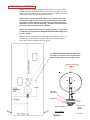
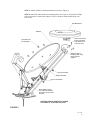
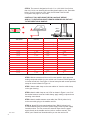
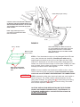
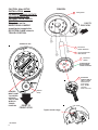
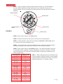
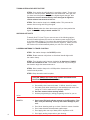
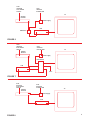
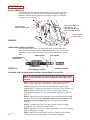
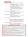
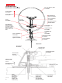
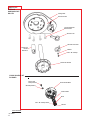
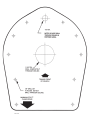
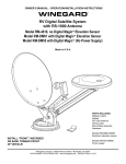
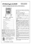
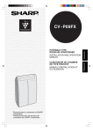
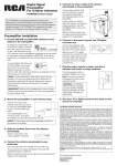
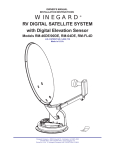
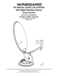
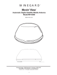
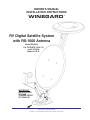
OWNER’S MANUAL
INSTALLATION INSTRUCTIONS
WINEGARD
RV Digital Satellite System
with RS-1000 Antenna
Model RD-4610
U.S. PATENTS 5,532,710
and 5,554,998
Made in U.S.A.
IMPORTANT:
INSTALL POINT
OF BASE
TOWARD FRONT
OF VEHICLE!
Winegard Company • 3000 Kirkwood St. • Burlington, IA 52601-2000
319/754-0600 • FAX 319/754-0787
Printed in U.S.A. © Winegard Company 2001 2451142 Rev. 6/05/01
®
INSTALLATION & ASSEMBLY
STEP 1. Choose a location for antenna that will allow it to rest in travel
position with antenna pointing toward rear of vehicle and raise and rotate
without interfering with other roof-mounted equipment. Make sure inside
ceiling area is clear where ceiling plate will mount.
NOTE: Figure 1 shows minimum distance (10") antenna should be
located from edge of vehicle roof. We recommend you check with
your dealer or the manufacturer to see what provisions have been
made in the roof for antenna mounting. A reinforced area of roof as
well as pre-wire downlead may be available.
NOTE: The system must be level for proper operation. If you have a
curved roof you should use a Winegard Model RW-1000 wedge kit to
level the system.
STEP 2. Position template on roof (last page of manual) and drill a 1-1/2"
hole through roof and ceiling of vehicle. Take care to avoid damage to
wiring which may run between roof and ceiling.
It is highly recomended that the antenna be
mounted on roof center line. Do not mount
antenna closer than 10" from edge of roof.
RW-1000
Roof Wedge
Vehicle Roof
Antenna Controls
Interior Roof
Wedge,
Optional
NOT TO SCALE
2
FIGURE 1
Rev. 2/2001
STEP 3. Attach reflector to backup assembly as shown in Figure 2.
STEP 4. Attach RS-1000 antenna to elevating tubes, see Figure 2, using the two Eclips
and pins provided. Attach coax cable to F-jack on antenna, slide weather boot over
boot collar.
RS-1000 Antenna
Reflector
Attach coax cable to
F-jack on antenna,
slide weather boot
over boot collar.
(4) 5/16-18 x 5/8"
Flat Head Bolt
Attach RS-1000 to
elevating tubes using
E-clips and pins
supplied.
(4) 5/16-18 Hex Nut
Backup Assembly
(4) 5/16" Flat Washer
NOTE: Make sure that
coax cables fits between
the reflector and the fixed
feed arm.
ANTENNA SHOWN PARTIALLY RAISED
FOR EASE OF ILLUSTRATION ONLY
FIGURE 2
Rev. 2/98
3
STEP 5. The mount is designed to fit roofs 1" to 4 3/4" thick. If roof is less
than 4 3/4" thick, cut elevating shft and directional handle to size. (See table
below.) If roof is more than 4 3/4" thick, the RP-2000 Thick Roof Kit
is required. See page 15, A for chart.
CAUTION: IF YOU ARE USING THE RW-1000 ROOF WEDGE,
ADD 1/2" TO ELEVATING SHAFT LENGTH GIVEN BELOW, BUT NOT
TO THE DIRECTIONAL HANDLE.
Directional
Handle
ROOF
THICKNESS
4 3/4"
4 1/2"
4 1/4"
4"
3 3/4"
3 1/2"
3 1/4"
3"
2 3/4"
2 1/2"
2 1/4"
2"
1 3/4"
1 1/2"
1 1/4"
ELEVATING SHAFT
LENGTH
6 1/4"
6"
5 3/4"
5 1/2"
5 1/4"
5"
4 3/4"
4 1/2"
4 1/4"
4"
3 3/4"
3 1/2"
3 1/4"
3"
2 3/4"
W/RW-1000
RP-4200 req.
RP-4200 req.
6 1/4"
6"
5 3/4"
5 1/2"
5 1/4"
5"
4 3/4"
4 1/2"
4 1/4"
4"
3 3/4"
3 1/2"
3"
DIRECTIONAL
HANDLE LENGTH
5 3/8"
5"
4 3/4"
4 1/2"
4 1/4"
4"
3 9/16"
3 3/8"
3 1/16"
2 3/4"
2 3/8"
2 1/16"
1 3/4"
1 3/8"
1"
STEP 6. Mount antenna and lift on roof in travel position. Apply approved
sealing compound suitable for your vehicle roof on bottom of base plate and
roof area around hole. See Figure 3. Secure base plate with screws provided,
except for screw indicated in Figure 3*.
STEP 7. Attach cable clamp to the coax cables 16" from the cable clamp
on the gear housing.
STEP 8. Attach cable clamp to roof of RV as shown in Figure 3, use 7/16"
flat washer between screw and cable clamp, apply sealing compound over
mounting screw heads.
STEP 9. Attach satellite antenna coax cable (has "RG-6" printed on it)
to the coax cable going to the satellite receiver.
Rev 1/2001
4
STEP 10. Attach RS-1000 coax downlead (has "RG-59" printed on it)
to coax downlead going to RV-0541 power supply. Refer to power supply
instruction sheet. You can connect the antenna output from the power
supply directly to the satellite receiver (refer to receiver manual). This
allows you to watch local channels when you turn the receiver off.
Cable clamp on gear housing.
CAUTION: DO NOT GET SEALING COMPOUND
ON BEARING SURFACE BETWEEN BASE PLATE
AND ROTATING GEAR HOUSING. DO NOT PAINT
TOP OF BASE PLATE OR AROUND ROTATING
GEAR HOUSING.
Cable Ties
NOTE: Apply sealant approved for
your vehicle roof between Base Plate
and roof of vehicle.
3" min.
FIGURE 3
#10 x 1" Screws
Make sure cable
entry is sealed
Apply approved sealant
under lip and cable roof
hole
INSIDE RV
Attach cable clamp here. Make sure there are
16" of coax between the cable clamp on the gear
housing and the one here 3" in front of base
plate. TOO MUCH OR TOO LITTLE WILL CAUSE
DAMAGE TO COAX.
STEP 11. Feed downleads through roof using Winegard Model CE-2000
cover plate (included with hardware). Weatherproof cable entry by
applying approved sealant under lip of roof-thru plate and where cable
enters roof. Attach plate to roof with screws provided. Apply approved
sealant over screws and around edge of roof-thru plate, making sure cable
entry is sealed. Secure cables as necessary to prevent whipping. Use
tie-wraps provided to secure cables together.
STEP 12. Connect satellite coax downlead to satellite receiver, refer to
receiver manual on proper connections. If coax connections are made
outside the coach YOU MUST WEATHERPROOF THE CONNECTIONS!
STEP 13. Assemble ceiling plate, directional handle and crank handle as
shown in Figure 4. The circled numbers indicate placement from the
ceiling down. Example: The ceiling plate 1 is located next to the ceiling.
The elevation crank handle 8 is farthest from the ceiling. The number
also indicates sequence of assembly.
CAUTION: USE CAUTION WHEN INSTALLING THE ELEVATING
CRANK. ONCE SCREW TOUCHES SHAFT, TIGHTEN ONLY 1/4
TURN MORE. SCREW SIMPLY HOLDS ELEVATING CRANK ON.
DO NOT OVERTIGHTEN!
5
CAUTION: After INITIAL
INSTALLATION,
the antenna SHOULD ROTATE
APPROXIMATELY 360
DEGREES FROM TRAVEL
POSITION.
The pointer on the
DIRECTIONAL HANDLE
should point towards the
ROTATION CLAMP when in
TRAVEL POSITION.
FIGURE 4
1
Ceiling Base
POINT TO
FRONT OF RV
ASSEMBLED VIEW
3
Directional
Handle Extension
2
(4) #10 Phillips Flat
Head Screws
4
Directional
Handle
ALIGN POINTER
WITH ANTENNA
TRAVEL POSITION
5
POINTER
MUST POINT
TO CENTER
OF ROTATION CLAMP
WHEN IN
TRAVEL
POSITION
Rotation
Clamp
POINT TO
FRONT OF RV
Tighten screw snugly
6
Rev 6/05/01
ELEVATING
CRANK HANDLE
(When installed,
extends 2-1/4"
from ceiling).
Snap Handle
into base
when not in use.
OPERATION
STEP 1. Using a compass, determine which direction is North. It is recommended that
you step outside to perform this step. Standing in or near coach/RV can give you an
incorrect reading. The more accurately you determine North, the easier it will be to find the
satellite(s).
Directional Handle
Elevating Crank
Directional Handle
Pointer
Directional Dial
FIGURE 5
Rotation Clamp
STEP 2. Move rotation clamp to the LOCK position.
STEP 3. Rotate directional dial (see Figure 5) until the arrow is pointing North.
STEP 4. Unsnap elevation crank and turn (clockwise) in direction of "UP" arrow, about
14 - 15 turns or until some resistance is met.
STEP 5. Turn receiver ON, and access installation menus to determine antenna elevation
and direction/heading. See receiver owner manual for menu access instructions.
STEP 6. Move rotation clamp to the ROTATE position. Turn directional handle until pointer
on directional handle is pointing in direction indicated by the receiver. Example: If receiver
says point antenna at 145° then rotate directional handle so that pointer is pointing at 145o
on the directional dial.
ELEVATION
14 - 16o
17 - 19o
20 - 22o
23 - 26
27 - 29o
30 - 32o
33 - 36o
37 - 39o
40 - 43o
44 - 46o
47 - 50o
51 - 53o
54 - 57o
58 - 60o
61 - 64o
65 - 67o
TURNS CCW
NONE
1/2
1
1-1/2
2
2-1/2
3
3-1/2
4
4-1/2
5
5-1/2
6
6-1/2
7
7-1/2
STEP 7. Refer to table below and turn elevation crank
counter clockwise (CCW) the number of turns indicated
to get the elevation shown by the receiver. One full turn
equals approximately 7° of elevation change.
Rev 7/97
7
TUNING ANTENNA FOR BEST PICTURE
STEP 8. Your receiver should indicate it is receiving a signal. To tune your
antenna for the best picture, slowly move the antenna left, then right until
you have found the position that gives the highest signal strength. It is
important to turn the antenna slowly; since the signal is digital the
receiver takes a few seconds to lock on.
STEP 9. Place rotation clamp in the LOCK position. This prevents the
antenna from moving and losing the signal.
STEP 10. Slowly raise then lower the antenna until you have peaked the
signal. You are now ready to watch satellite TV!
WATCHING OFF-AIR TV
To watch off-air TV (local TV) you must use one of the following options;
Use a A-B switch between the receiver and antenna power supply Figure
6), A video switch (Figure 7), Or connect the antenna output from the power
supply to the TV ANTENNA input on the receiver (Figure 8). When you turn
the receiver off it will automatically switch you over to the off-air signal.
LOWERING ANTENNA TO TRAVEL POSITION
STEP 1. Set rotation clamp to the ROTATE position.
STEP 2. Rotate antenna until pointer on directional handle aligns with
the rotation clamp.
STEP 3. Turn elevating crank (counter clockwise) in direction of "DOWN"
arrow until resistance is met. The number of turns will vary according to
the elevation angle the antenna was set to.
STEP 4. Move rotation clamp to the LOCK position. Antenna is now
locked in travel position.
STEP 5. Snap elevation crank into place.
CAUTION: UNDER NO CONDITIONS LOWER ANTENNA IN ANY
POSITION EXCEPT TRAVEL POSITION.
DO’S
1. Do check parking location for obstructions before raising antenna.
2. Do carefully raise, lower and rotate - if difficult, check for cause.
3. Do rotate slowly when searching for the satellite(s) and check fine
tuning on TV set to make sure it is properly adjusted.
4. Do lower antenna before moving vehicle.
5. Activate programming by calling programing service for your re-
ceiver.
DON’T’S
8
1. Don't move RV/coach with the antenna in the UP position. This
WILL void your warranty. This may also cause damage to your
roof.
2. Don’t force elevating crank up or down. Check for cause of trouble.
3. Don’t rotate directional handle hard against stops.
4. Don’t apply paint over top of base plate or anywhere on lift.
5. Don't apply sealing compound on gear housing.
Coax
downlead
from satellite
antenna
Coax
downlead
from RS-1000
TV
Satellite
Receiver
Power Supply
VCR
A-B Switch
FIGURE 6
Coax
downlead
from satellite
antenna
Coax
downlead
from RS-1000
TV
Satellite
Receiver
Power Supply
Video Switch
VCR
Set 2
FIGURE 7
Coax
downlead
from satellite
antenna
Satellite
Receiver
Coax
downlead
from RS-1000
TV
Power Supply
VCR
FIGURE 8
9
MAINTENANCE
MOUNT LUBRICATION
To lubricate the mount, apply a liberal amount of silicone spray lubricant to
the elevating gear, the lubricant hole and between the gear housing and
baseplate. Run the antenna up/down and rotate the antenna to distribute
the lubricant. See Figure 9.
Remove cap and spray
lubricant into the
lubricate hole. Be sure
place cap firmly back on.
Spray lubricant
here on elevation gear
Spray lubricant
around edges
FIGURE 9
LUBRICATING RUBBER QUAD RING
Lubricate rubber quad ring on elevating shaft which is below worm gear
with silicone spray lubricant at least twice yearly (Figure 10). This will keep
quad ring from becoming brittle which could result in leaks down elevating
shaft.
ELEVATING SHAFT
WORM GEAR
FIGURE 10
WAVE WASHER
LOWER BEARING SURFACE
FLAT WASHER
RUBBER QUAD RING
ELEVATING SHAFT & WORM GEAR ASSEMBLY REPLACEMENT PROCEDURE
NOTE: It is not necessary to remove rotating gear housing from base
plate or remove antenna from roof to replace the shaft & worm gear
assembly.
STEP 1. Lower antenna to travel position. Loosen screw on elevating
crank, remove crank, spring, directional handle. Parts list page 14.
STEP 2. Remove hex nuts, cable clip, and washer from bolt holding
elevating tube in rotating gear housing and remove bolt. Parts list page 12.
STEP 3. Remove worm gear nut from top of rotating gear housing,
disengage elevating gear, remove elevating shaft assembly. A, Parts list
page 12.
STEP 4. Lubricate worm gear assembly on new elevating shaft assembly
with spray silicone lubricant. Make sure wave washer, flat washer and
quad ring are on lower bearing (Figure 10) and insert assembly in
housing.
STEP 5. Reinstall worm gear nut in top of housing. Gears will mesh
automatically once elevating crank is turned.
STEP 6. Reinstall bolt, hex nuts, cable clip and washers that hold elevating
tube in rotating gear housing.
10
Rev 1/97
STEP 7. Replace directional handle, spring and elevating crank. Make
sure set screw contacts flat surface on shaft before tightening.
TROUBLE SHOOTING
NO PICTURE
1. Check that you have a clear line of sight to the satellite (no trees,
buildings, etc.).
2. Check that you have the TV set tuned for the correct channel 3 or 4
(same channel as output of receiver).
3. Double check that you have entered the correct zip code into the
receiver. If zip code is wrong, this can cause you to look in the
wrong direction/elevation for the satellite.
4. Check connections at receiver, TV, and antenna.
5. Check TV. Does it receive pictures from off-air TV stations/VCR?
6. Retune system for best picture per procedure on page 7.
7. Inspect antenna. Make sure that it has not been damaged. If
antenna is even slightly bent, the receiver may not receive any
signal.
8. Contact Dealer or Winegard Service Department.
ANTENNA DOES NOT OR IS HARD TO ROTATE
1. Inspect antenna on roof. Make sure mount has not been damaged.
2. Check for caulking between gear housing and baseplate.
3. Lubricate mount per procedure on page 8.
4. Contact Dealer or Winegard Service Department.
ANTENNA DOES NOT OR IS HARD TO RAISE
1. Inspect antenna on roof. Make sure mount has not been damaged.
2. Check for caulking on elevating shaft.
3. Lubricate elevating shaft per procedure on page 8.
4. Contact Dealer or Winegard Service Department.
WARRANTY REPAIR WORK
Before you have warranty work done on the system, make sure the
company/person performing the work has been approved by Winegard
Company. If not, contact Winegard Co. (1-800-288-8094) before
proceeding. The Winegard warranty covers only the mount, antenna
and LNBF. For receiver warranty, refer to the manufacturers warranty.
ORDERING REPAIR PARTS
Repair parts are available at many RV dealers and/or service centers
throughout the country. Or you can call Winegard Company
1-800-288-8094 (only credit card orders accepted).
ANTENNA/LIFT/LNBF TWO YEAR LIMITED WARRANTY
Winegard Company warrants this Winegard product (excluding receiver) against any defects in materials or workmanship within two (2)
yeares from date of purchase. No warranty claim will be honored unless at the time the claim is made, you present proof of purchase to an
authorized Winegard dealer (if unknown, please contact Winegard Company, 3000 Kirkwood Street, Burlington, Iowa 52601-2000, telephone
319-754-0600).
Winegard Company (at its option) will either repair or replace the defective product at no charge to you. This warranty covers parts, but does
not cover any costs incurred in removal, shipping or reinstallation of the product. This limited warranty does not apply if the product is
damaged, deteriorates, malfunctions or fails from: misuse, improper installation, abuse, neglect, accident, tampering, modification of the
product as originally manufactured by Winegard, usage not in accordance with product instructions or acts of nature such as damage caused
by wind, lightning, ice or corrosive environments such as salt spray and acid rain.
The Two Year Warranty is provided on the condition that the equipment is properly delivered with all handling and freight charges prepaid
to your Winegard dealer for repair or return to our factory at the above address. Winegard dealers will arrange for the replacement or repair
and return to you, without charge, the product which failed due to defective material or workmanship.
WINEGARD COMPANY WILL NOT ASSUME ANY LIABILITIES FOR ANY OTHER WARRANTIES, EXPRESS OR IMPLIED, MADE BY
ANY OTHER PERSON.
ALL OTHER WARRANTIES WHETHER EXPRESS, IMPLIED OR STATUTORY INCLUDING WARRANTIES OF FITNESS FOR A
PARTICULAR PURPOSE AND MERCHANTABILITY ARE LIMITED TO THE TWO YEAR PERIOD OF THIS WRITTEN WARRANTY.
The foregoing shall be the sole and exclusive remedy of any person whether in contract, tort or otherwise, and Winegard shall not be liable
for incidental or consequential damage or commercial loss, or from any other loss or damage except as set forth above.
Some states do not allow limitations on how long an implied warranty lasts, or the exclusion of limitation of incidental or consequential
damages, so the above limitations or exclusions may not apply to you.
This warranty gives you specific legal rights and you may also have other rights which vary from state to state.
11
PARTS LIST
(not all parts listed
due to space constraints)
46cm (18") Reflector, White
P.N. 2745304
(4) 5/16" Hex Nut
P.N. 2160230
(4) 5/16" Flat Washer
P.N. 2160027
(2) 1/4-20 Hex Nut,
Nylock P.N. 2160220
Backup
P.N. 2745348
(4) 1/4" Flat Washer
P.N. 2160039
(5) E-Clip
P.N. 5160818
(2) 1/4-20 X 1.75" Hex
Bolt P.N. 2160238
Digital Elevation
Device, If attached
the 1/4-20 x 1.75 Hex
Bolts are replaced
with 1/4-20 x 2" Hex
Bolts
(3) 1/4 x 2-5/16" Pin
P.N. 2160814
Bumper Assembly
P.N. 3750823
(2) 1/4-20 X 1.75"
BOLT
P.N. 2160238
(2) 1/4" Flat Washer
P.N. 2160039
(4) 1/4-20 Hex Nut,
Nylock P.N. 2160220
1/4-20 X 2.5" Hex Bolt
P.N. 2160237
A
(2) 1/4" Flat Washer
P.N. 2160024
REAR VIEW
Worm Gear Nut
P.N. 2200045
Model RP-3000
Elevating Gear
Upper Elevating Tube
P.N. 3506032
Aluminum Gear
Housing
P.N. 3100520
(10) #10 x 1" Hex
Head Screw P.N.
2160178
Aluminum Baseplate
P.N. 3100524
Rev 4/98
12
Washer
P.N. 3200657
Retaining Nut
P.N. 2200047
(requires 15/16"
socket wrench)
Lower Elevating Tube
P.N. 3506033
Model RP-4000
Worm Gear &
Retaining Plug
See replacement
procedure on page 8.
Nylon Bearing
P.N. 3200656
PARTS LIST
Upper Elevating Tub
P.N. 3506032
RS-1000
Mount Adapter
P.N. 2200114
Bolt
P.N. 3200350
Lower Elevating Tube
P.N. 3506033
LNBF is attached to pivot arm
with: 1/4-20 x 1/2" Cap Screw
P.N. 2160240
1/4-20 Nylock Hex Nut
P.N. 2160220
LNBF
P.N. 2780161
(2) 1/4" Washer
P.N. 2160024
(4) Flat Head Bolts
(white) P.N. 2160361
(3) 1/4 x 2-5/16" Pin
P.N. 2160814
(2) Travel Link
P.N. 2745050
LNBF Pivot Arm
P.N. 2745059
Spring
P.N. 2160820
(not shown
for clarity)
Fixed Feed Arm
P.N. 2745063
(4) Nylon Bearing
P.N. 2200726
(not shown
for clarity)
Travel Alignment Bracket
P.N. 2745061
(2) Cable Clamp
P.N. 2200060
(4) 1/4-20 Hex Nut,
Nylock P.N. 2160220
(2) 1/4 x 1-7/8" Pin
P.N. 2160694
Rev. 5/99
(5) E-Clips
P.N. 5160818
NOT TO SCALE
Coaxial Cable
RD-4600 20'
P.N. 2753025
RD-4646 76"
P.N. 2753064
13
PARTS LIST
INTERIOR
HARDWARE KIT
RK-CEIL
Ceiling Base
Directional Dial
(4) #10 Phillip Flat
Head Screws
Azimuth Lock
Azimuth Lock Knob
Directional
Handle
Extension
Washer
#10 x 3/8" Phillips
Directional Handle
CRANK HANDLE KIT
RK-HAND
#8-32 x 3/8"
Phillips Screw
Crank Handle Base
#8-32 Square Nut
Crank Handle
Knob
#10 x 3/8" Phillips Screw
Washer
NOT TO SCALE
Rev 6/05/01
14
SPECIFICATIONS
Height when raised
Height in the travel position
Operating radius
Roof space required
LNB
Color
Satellite antenna height
Satellite antenna width
F/D
Offset angle
Frequency range
Satellite antenna gain:
11.2 GHz
12.1 GHz
12.6 GHz
Aperture efficiency
Cross polarization (on axis)
*Beamwidth at -3 dB
*Beamwidth at -10 dB
RS-100 antenna gain
VHF
UHF
RS-1000 antenna height
RS-1000 antenna width
Wind loading
Weight
Shipping weight:
37" max.
12.0" max.
17" (34" diameter circle)
19.5" x 46.75"
Compatible with DSS® and DISH NetworkTM
White
20.9"
19.5"
0.59
24o
10.95 - 12.75 GHz
33.22 dBi
33.89 dBi
34.23 dBi
73%
-21 dB
3.5o
7.0o
15.5 dB avg.
19.5 dB avg.
3.25"
14.5"
Up to hurricane force
19 lbs. max.
21 lbs.
DSS® is a registered trademark of DIRECTV, Inc. a unit of Hughes Electronics Corporation.
DISH NetworkTM is a trademark and a service mark of EchoStar Communications Corporation.
MODEL RP-4200 THICK ROOF KIT AVAILABLE
Winegard Company makes available Model RP-4200 which includes one
directional handle extension and elevating shaft worm gear assembly. The
RP-4200 is designed for roofs more than 4 3/4" to 6 3/4" thick. Contact
Winegard Company if roof thickness measures more than 6 3/4". Refer to
the table below for the correct directional handle and elevating shaft
measurements. Remember to glue extensions (PVC glue is recommended)
and handle together after checking that you have the correct length.
ROOF
THICKNESS
6 3/4"
6 1/2"
6 1/4"
6"
5 3/4"
5 1/2"
5 1/4"
5"
ELEVATING
SHAFT LENGTH
8 1/4"
8"
7 3/4"
7 1/2"
7 1/4"
7"
6 3/4"
6 1/2"
W/RW-1000
8 3/4"
8 1/2"
8 1/4"
8"
7 3/4"
7 1/2"
7 1/4"
7"
DIRECTIONAL
HANDLE LENGTH
5 1/8"
7 1/8"
6 7/8"
6 5/8"
6 3/8"
6 1/8"
5 7/8"
5 5/8"
Extension
2 1/4"
Not Required
Not Required
Not Required
Not Required
Not Required
Not Required
Not Required
Rev 1/2001
Printed in U.S.A. Winegard Company • 3000 Kirkwood Street • Burlington, Iowa 52601-2000 © Winegard Company, 2001 2451142 Rev. 6/05/01
15
Rev. 8-97