1
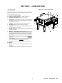
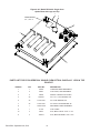
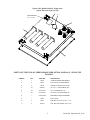
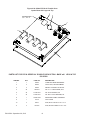
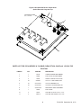
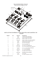
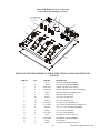
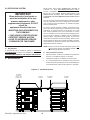
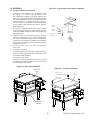
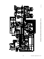
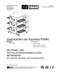
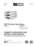
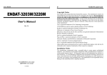
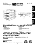
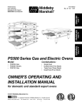
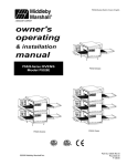
PS740 Series Electric Domestic & Std. Export ENGLISH P/N 60254 September 28, 2012 PS740 Series Electric Ovens Model: • PS740E Electric Combinations: • • • Single Oven Double Oven (Two-Stack) Triple Oven (Three-Stack) OWNER'S OPERATING AND INSTALLATION MANUAL for domestic and standard export ovens ©2012 Middleby Marshall Inc. is a registered trademark of Middleby Marshall, Inc. All rights reserved. Middleby Cooking Systems Group • 1400 Toastmaster Drive • Elgin, IL 60120 • (847)741-3300 • FAX (847)741-4406 NOTICE: This Owner's Operating and Installation Manual should be given to the user. The operator of the oven should be familiar with the functions and operation of the oven. This manual must be kept in a prominent, easily reachable location near the oven. It is suggested to obtain a service contract with a Middleby Marshall Authorized Service Agent. WARNING FOR YOUR SAFETY, DO NOT STORE OR USE GASOLINE OR OTHER FLAMMABLE VAPORS AND LIQUIDS IN THE VICINITY OF THIS OR ANY OTHER APPLIANCE. WARNING Improper installation, adjustment, alteration, service, or maintenance can cause property damage, injury, or death. Read the installation, operation, and maintenance instructions thoroughly before installing or servicing this equipment. IMPORTANT An electrical wiring diagram for the oven is located inside the machinery compartment. IMPORTANT It is the customer’s responsibility to report any concealed or non-concealed damage to the freight company. Retain all shipping materials until it is certain that the equipment has not suffered concealed shipping damage. NOTICE CONTACT YOUR MIDDLEBY MARSHALL AUTHORIZED SERVICE AGENT TO PERFORM MAINENANCE AND REPAIRS. AN AUTHORIZED SERVICE AGENCY DIRECTORY IS SUPPLIED WITH YOUR OVEN. NOTICE Using any parts other than genuine Middleby Marshall factory manufactured parts relieves the manufacturer of all warranty and liability. NOTICE Middleby Marshall (Manufacturer) reserves the right to change specifications at any time. NOTICE The equipment warranty is not valid unless the oven is installed, started and demonstrated under the supervision of a factory certified installer. NOTICE A Middleby Marshall certified installer must be used to install and service this appliance. NOTICE This equipment is only for professional use and shall be used by qualified people. RETAIN THIS MANUAL FOR FUTURE REFERENCE. Middleby Cooking Systems Group • 1400 Toastmaster Drive • Elgin, IL 60120 USA • (847)741-3300 • FAX (847) 741-4406 www.middleby.com P/N 60254 September 28, 2012 II Model No. Modéle No. Serial No. Serié No. Installation Date Date d'installation MIDDLEBY MARSHALL No Quibble Limited Warranty (U.S.A. Only) MIDDLEBY MARSHALL INC. OVEN LIMITED WARRANTY (Non U.S.A.) The Seller warrants equipment manufactured by it to be free from defects in material and workmanship for which it is responsible. The Seller’s obligation under this warranty shall be limited to replacing or repairing, at Seller’s option, without charge, F.O.B. Seller’s factory, any part found to be defective and any labor and material expense incurred by Seller in repairing or replacing such part. Such warranty is limited to a period of one year from date of original installation or 15 months from date of shipment from Seller’s factory, whichever is earlier, provided that terms of payment have been fully met. All labor shall be performed during regular working hours. Overtime premium will be charged to the Buyer. MIDDLEBY MARSHALL, HEREINAFTER REFERRED TO AS “THE SELLER”, WARRANTS EQUIPMENT MANUFACTURED BY IT TO BE FREE FROM DEFECTS IN MATERIAL AND WORKMANSHIP FOR WHICH IT IS RESPONSIBLE. THE SELLER’S OBLIGATION UNDER THIS WARRANTY SHALL BE LIMITED TO REPLACING OR REPAIRING, AT SELLER’S OPTION, WITHOUT CHARGE, ANY PART FOUND TO BE DEFECTIVE AND ANY LABOR AND MATERIAL EXPENSE INCURRED BY SELLER IN REPAIRING OR REPLACING SUCH PART. SUCH WARRANTY SHALL BE LIMITED TO THE ORIGINAL PURCHASER ONLY AND SHALL BE EFFECTIVE FOR A PERIOD OF ONE YEAR FROM DATE OF ORIGINAL INSTALLATION, OR 18 MONTHS FROM DATE OF PURCHASE, WHICHEVER IS EARLIER, PROVIDED THAT TERMS OF PAYMENT HAVE BEEN FULLY MET. This warranty is not valid unless equipment is installed, started, and demonstrated under the supervision of a factoryauthorized installer. Normal maintenance functions, including lubrication, adjustment of airflow, thermostats, door mechanisms, microswitches, burners and pilot burners, and replacement of light bulbs, fuses and indicating lights, are not covered by warranty. This warranty is valid only if the equipment is installed, started, and demonstrated under the supervision of a factoryauthorized installer. Any repairs or replacements of defective parts shall be performed by Seller’s authorized service personnel. Seller shall not be responsible for any costs incurred if the work is performed by other than Seller’s authorized service personnel. Normal maintenance functions, including lubrication, cleaning, or customer abuse, are not covered by this no quibble warranty. When returning any part under warranty, the part must be intact and complete, without evidence of misuse or abuse, freight prepaid. Seller shall be responsible only for repairs or replacements of defective parts performed by Seller’s authorized service personnel. Authorized service agencies are located in principal cities throughout the contiguous United States, Alaska, and Hawaii. This warranty is valid in the 50 United States and is void elsewhere unless the product is purchased through Middleby International with warranty included. Seller shall not be liable for consequential damages of any kind which occur during the course of installation of equipment, or which result from the use or misuse by Buyer, its employees or others of the equipment supplied hereunder, and Buyer’s sole and exclusive remedy against Seller for any breach of the foregoing warranty or otherwise shall be for the repair or replacement of the equipment or parts thereof affected by such breach. The foregoing warranty is exclusive and in lieu of all other warranties, expressed or implied. There are no implied warranties of merchantability or of fitness for a particular purpose. The foregoing warranty shall be valid and binding upon Seller if and only if Buyer loads, operates and maintains the equipment supplied hereunder in accordance with the instruction manual provided to Buyer. Seller does not guarantee the process of manufacture by Buyer or the quality of product to be produced by the equipment supplied hereunder and Seller shall not be liable for any prospective or lost profits of Buyer. The foregoing shall be Seller’s sole and exclusive obligation and Buyer’s sole and exclusive remedy for any action, including breach of contract or negligence. In no event shall Seller be liable for a sum in excess of the purchase price of the item. Seller shall not be liable for any prospective or lost profits of Buyer. THE FOREGOING WARRANTY IS EXCLUSIVE AND IN LIEU OF ALL OTHER EXPRESS AND IMPLIED WARRANTIES WHATSOEVER. SPECIFICALLY THERE ARE NO IMPLIED WARRANTIES OF MERCHANTABILITY OR OF FITNESS FOR A PARTICULAR PURPOSE. This warranty is effective on Middleby Marshall equipment sold on, or after, February 15, 1995. The foregoing shall be Seller’s sole and exclusive obligation and Buyer’s sole and exclusive remedy for any action, whether in breach of contract or negligence. In no event shall seller be liable for a sum in excess of the purchase price of the item. © 2003 - Middleby Marshall, A Middleby Company. The Middleby Marshall logo is a registered trademark of Middleby Marshall, A Middleby Company. Middleby Marshall Inc. • 1400 Toastmaster Drive • Elgin, Illinois 60120-9272 U.S.A. • (847) 741-3300 • FAX: (847) 741 4406 III P/N 60254 September 28, 2012 TABLE OF CONTENTS .Page SECTION 3 – OPERATION .............................................. 19 I. LOCATION AND DESCRIPTION OF CONTROLS. 19 II. NORMAL OPERATION, STEP-BY-STEP............... 20 A. Main Screen................................................. 20 B. Daily Startup Procedure............................... 20 C. Daily Shutdown Procedure........................... 20 III. QUICK REFERENCE: TROUBLESHOOTING........ 21 IV. SCREEN ALERTS................................................... 21 Page SECTION 1 – DESCRIPTION ............................................. 1 I. OVEN USES.............................................................. 1 II. OVEN COMPONENTS.............................................. 1 A. Conveyor Motor Drive.................................... 1 B. Crumb Pans................................................... 1 C. Conveyor........................................................ 1 D. End Plugs....................................................... 1 E. Eyebrows........................................................ 1 F. Window........................................................... 1 G. Machinery Compartment Access Panel......... 1 H. Serial Plate..................................................... 1 I. Control Panel.................................................. 1 J. Photo Cell....................................................... 1 K. Blowers........................................................... 1 L. Air Fingers...................................................... 1 III. OVEN SPECIFICATIONS.......................................... 2 A. Dimensions..................................................... 2 B. General Specifications................................... 2 C. Electrical Specifications for PS740 Electric Ovens.................................... 2 SECTION 2 – INSTALLATION ........................................... 3 I. BASE PAD KIT.......................................................... 4 II. INSTALLATION KIT................................................... 6 III. VENTILATION SYSTEM......................................... 12 A. Requirements............................................... 12 B. Recommendations....................................... 12 C. Other Ventilation Concerns.......................... 12 IV. ASSEMBLY............................................................. 13 A. Base Pad, Legs, Casters.............................. 13 B. Stacking........................................................ 14 C. Restraint Cable Installation.......................... 14 D. Conveyor Installation.................................... 15 E. Standoff Installation...................................... 15 V. FINAL ASSEMBLY.................................................. 16 VI. ELECTRICAL SUPPLY........................................... 17 Connection........................................................ 17 UTILITY ROUGH-IN DIMENSIONS AND.................... POSITIONING FOR PS840-SERIES OVENS................... 18 Circuit Breaker................................................... 18 Electrical Specifications..................................... 18 Electrical Rating................................................ 18 Supply Wire....................................................... 18 Suggested......................................................... 18 P/N 60254 September 28, 2012 SECTION 4 – MAINTENANCE ......................................... 22 I. MAINTENANCE – DAILY........................................ 22 II. MAINTENANCE – MONTHLY................................. 23 III. MAINTENANCE – EVERY 3 MONTHS................... 24 IV. MAINTENANCE – EVERY 6 MONTHS................... 25 V. KEY SPARE PARTS KIT......................................... 26 SECTION 5 – TROUBLESHOOTING................................ 27 SECTION 6 – ELECTRICAL WIRING DIAGRAM............. 28 WIRING DIAGRAM, 740 Electric Oven, E208/240V, 50/60 Hz, 3 Ph............................................................... 28 WIRING DIAGRAM, 740 Electric Oven, E380-480V, 50/60 Hz, 3 Ph............................................................... 29 NOTE Wiring Diagrams are in Section 6 of this Manual. The diagram for each oven is also on the lower inner surface of its Control Console. IV SECTION 1 – DESCRIPTION Figure 1-1. Oven Components I. OVEN USES PS740 Series Ovens can be used to bake and/or cook a wide variety of food products, such as pizza, pizza –type products, cookies, sandwiches and others. II. OVEN COMPONENTS – see Figure 1-1. A. Conveyor Drive Motor: Moves the conveyor. B. Crumb Pans: Catch crumbs and other materials that drop through the conveyor belt. One crumb pan is located at each end of the conveyor. C. Conveyor: Moves the food product through the oven. D. End Plugs: Allow access to the oven’s interior. E. Eyebrows: Can be adjusted to various heights to prevent heat loss into the environment. F. Window: Allows the user to access food products inside the baking chamber. G. Machinery Compartment Access Panel: Allows access to the oven’s interior and control components. No user serviceable parts are located in the machinery compartment. H. Serial Plate: Provides specifications for the oven that affect installation and operation. Refer to Section 2, Installation for details. I. Control Panel: Location of the operating controls for the oven. Refer to Section 3, Operation, for details. J. Photo Cell: Turns oven On when beam is interrupted. Not Shown: K. Blowers: Project hot air from the heating element to the air fingers. L. Air Fingers: Project streams of hot air onto the food product. 1 P/N 60254 September 28, 2012 I. OVEN SPECIFICATIONS Table 1-1 Dimensions Single Oven Double Oven Overall Height 48-3/16″ (1219mm) 62-3/4″ (1575mm) Triple Oven 78-11/16″ (1981mm) Overall Depth 60″ (1524mm) 60″ (1524mm) 60″ (1524mm) Overall Length 76-1/2″ (1930mm) 76-1/2″ (1930mm) 76-1/2″ (1930mm) 32″ Conveyor Model 33-1/2″ (838mm) or 2 × 15″ (381mm) 33-1/2″ (838mm) or 2 × 15″ (381mm) 33-1/2″ (838mm) or 2 × 15″ (381mm) 24″ Conveyor Model Overall Depth Overall Length * All other dimension are the same Recommended Minimum Clearances Single Oven 52.75″ (1340mm) 69″ (1753mm) Double Oven 52.75″ (1340mm) 69″ (1753mm) Triple Ove 52.75″ (1340mm) 69″ (1753mm) Rear of Oven to Wall 3″ (76mm) 3″ (76mm) 3″ (76mm) Control end of conveyor to Wall 1″ (25.4mm) 1″ (25.4mm) 1″ (25.4mm) Non-control end of conveyor to Wall) 1″ (25.4mm) 1″ (25.4mm) 1″ (25.4mm) Table 1-2: General Specifications PS740 ELECTRIC Weight 1150 lbs. (522kg) Rated Heat Input 27.0 kW/hr (92,128 BTU, 23,216 kcal) Maximum Operation Temperature 600°F / 315°C Air Blowers Two Blowers at 1900 RPM Warmup Time 15 min. SERIES PS740 ELECTRICAL SPECIFICATIONS Main Blower & Elements Voltage Control Circuit Phase Frequency Voltage Amperage Draw Poles 208-240V 3 Ph 50/60 Hz 100 Amp 3 Pole HEATER AMPERAGE Wires 4 Wire (3 hot, 1 grd) Voltage kW Average Amps 208-240V L1 L2 L3 208 27 85 75 75 240 27 75 75 65 208-240V 3 Ph 50/60 Hz 75 Amp 4 Pole HEATER AMPERAGE 380V Voltage kW Average Amps N L1 L2 L3 380-480 27 51 41 41 10 208-240V 3 Ph 50/60 Hz 60 Amp HEATER AMPERAGE Voltage kW Average Amps L1 L2 L3 480 27 43 33 33 480V N 10 5 Wire (3 hot, 1neut, 1 grd) 4 Pole 5 Wire (3 hot, 1neut, 1 grd) IMPORTANT – Additional electrical information is provided on the oven’s serial plate, and on the wiring diagram inside the machinery compartment. NOTE Wiring Diagrams are contained in Section 6 of this Manual and are also located inside the oven at the bottom of the Control Panel This Manual Must Be Kept For Future Reference P/N 60254 September 28, 2012 2 SECTION 2 – INSTALLATION WARNING – After any conversions, readjustments, or service work on the oven: • Check that the ventilation system is in operation. WARNING - Keep the appliance area free and clear of combustibles. WARNING – The oven must be installed on an even (level) non-flammable flooring and any adjacent walls must be non-flammable. Recommended minimum clearances are specified in the Description section of this manual. WARNING – Do not obstruct the flow of ventilation air to and from your oven. There must be no obstructions around or underneath the oven. Constructional changes to the area where the oven is installed shall not affect the air supply to the oven. CAUTION: To reduce the risk of fire, the appliance is to be mounted on floors of noncombustible construction with noncombustible flooring and surface finish and with no combustible material against the underside thereof, or on noncombustible slabs or arches having no combustible material against the underside thereof, such construction shall in all cases extend not less than 12 inches (304mm) beyond the equipment on all sides. CAUTION: For additional installation information, contact your local Authorized Service Agent. NOTE – There must be adequate clearance between the oven and combustible construction. Clearance must also be provided for servicing and for proper operation. NOTE – An electrical wiring diagram for the oven is located inside the machinery compartment. NOTE: All aspects of the oven installation, including placement, utility connections, and ventilation requirements, must conform with any applicable local, national, or international codes. These codes supersede the requirements and guidelines provided in this manual. NOTE: In the USA, the oven installation must conform to local codes. Electric ovens, when installed, must be electrically grounded in accordance with local codes, or in the absence of local codes, with the National Electrical Code (NEC), or ANSI/NFPA70. NOTE: In Canada, the oven installation must conform with local codes. Electric ovens, when installed, must be electrically grounded in accordance with local codes, or in the absence of local codes, with the Canadian Electrical Code CSA C22.2. 3 P/N 60254 September 28, 2012 PS740 24″ OVEN INSTALLATION REQUIRED KITS AND EQUIPMENT PS740 Electric Oven Installation TYPE OF INSTALLATION Kit P/N61453 PS740 Single Oven Option Base w/ 15″ Legs, Casters & Top Kit P/N61123 PS740 DoubleOven OptionBase w/ 6″ Legs, Casters & Top Kit P/N61457 PS740 Single Gas Oven 1 PS740 Double Gas Oven 2 PS740 Triple Gas Oven 3 PS740 TripleOven OptionBase w/ Casters& Top Kit P/N61458 1 1 1 PARTS LIST FOR SERIES PS740 ELECTRIC OVEN INSTALLATION KIT P/N 61453 (Two required for double oven) (Three required for triple oven) ITEM NO. QTY PART NO. 1 1 61823 CONVEYOR END STOP 2 1 31461 CONVEYOR LEFT REAR STOP 3 1 42612 SERVICE AGENCY DIRECTORY 4 1 22500-0080 5 1 51054 DESCRIPTION LABEL, MM ASSY, HANDLE & DOOR Figure 2-1A. PS740-Series Electric Oven Installation Parts 1 2 5 4 3 P/N 60254 September 28, 2012 4 PS740 OVEN INSTALLATION REQUIRED KITS AND EQUIPMENT PS740 Electric Oven Installation TYPE OF INSTALLATION Kit P/N61824 PS740 Single Oven Option Base w/ 15″ Legs, Casters & Top Kit P/N67025 PS740 DoubleOven OptionBase w/ 6″ Legs, Casters & Top Kit P/N67026 PS740 Single Electric Oven 1 PS740 Double Electric Oven 2 PS740 Triple Electric Oven 3 PS740 TripleOven OptionBase w/ Casters& Top Kit P/N66164 1 1 1 PARTS LIST FOR SERIES PS740 ELECTRIC OVEN INSTALLATION KIT P/N 61824 (Two required for double oven) (Three required for triple oven) ITEM NO. QTY PART NO. 1 1 61823 CONVEYOR END STOP 2 1 55027 CONVEYOR LEFT REAR STOP 3 1 42612 SERVICE AGENCY DIRECTORY 4 1 22500-0080 5 1 51054 DESCRIPTION LABEL, MM ASSY, HANDLE & DOOR Figure 2-1B. PS740-Series Electric Oven Installation Parts 1 2 5 4 3 5 P/N 60254 September 28, 2012 Figure 2-2A. Model PS740 24″ Single Oven Option Base with Legs and Top 1 8 HARDWARE BAG 5, 6, 7, 10 & 11 4 2 9 PARTS LIST FOR PS740 SERIES 24″ SINGLE OVEN OPTION - BASE w/15″ LEGS & TOP P/N 67027 ITEM NO. QTY PART NO. 1 1 64943 COMPLETE BASE WELDMENT 2 4 66851 TOP PLATE, LEG WELDMENT 4 4 58930 SWIVEL CASTER FLAT PLATE 5 32 2000531 3/8″-16 × 1″ HEX SCREW, SST 6 32 21416-0001 3/8″ FLAT WASHER, SS 7 32 21422-0001 3/8″ SPLIT LOCK WASHER, ZP 8 1 22450-0228 RESTRAINT CABLE ASSEMBLY 9 1 61125 TOP COVER 10 2 59677 SCR, MS SL TR HD 10-32 × 2-1/2″ 11 2 7A2S15 SCR, MS STR TRSHD 10-32 × 3/4″ P/N 60254 September 28, 2012 DESCRIPTION 6 Figure 2-2B. Model PS740 32″ Single Oven Option Base with Legs and Top 1 8 HARDWARE BAG 5, 6, 7, 10 & 11 4 2 9 PARTS LIST FOR PS740 32″ SERIES SINGLE OVEN OPTION - BASE w/15″ LEGS & TOP P/N 67025 ITEM NO. QTY PART NO. 1 1 66159 DESCRIPTION COMPLETE BASE WELDMENT 2 4 66851 TOP PLATE, LEG WELDMENT 4 4 58930 SWIVEL CASTER FLAT PLATE 5 32 2000531 3/8″-16 × 1″ HEX SCREW, SST 6 32 21416-0001 3/8″ FLAT WASHER, SS 7 32 21422-0001 3/8″ SPLIT LOCK WASHER, ZP 8 1 22450-0228 RESTRAINT CABLE ASSEMBLY 9 1 59560 TOP COVER 10 2 59677 SCR, MS SL TR HD 10-32 × 2-1/2″ 11 2 7A2S15 SCR, MS STR TRSHD 10-32 × 3/4″ 7 P/N 60254 September 28, 2012 Figure 2-3A. Model PS740 24″ Double Oven Option Base with Legs and Top 1 8 HARDWARE BAG 5, 6, 7, 10 & 11 4 2 9 PARTS LIST FOR PS740 SERIES 24″ DOUBLE OVEN OPTION - BASE w/6″ LEGS & TOP P/N 67028 ITEM NO. QTY PART NO. 1 1 64943 COMPLETE BASE WELDMENT 2 4 66853 TOP PLATE, LEG WELDMENT 4 4 58930 SWIVEL CASTER FLAT PLATE 5 32 2000531 3/8″-16 × 1 HEX SCREW, SST 6 32 21416-0001 3/8″ FLAT WASHER, SS 7 32 21422-0001 3/8″ SPLIT LOCK WASHER, ZP 8 1 22450-0228 RESTRAINT CABLE ASSEMBLY 9 1 61125 TOP COVER 10 2 59677 SCR, MS SL TR HD 10-32 × 2-1/2″ 11 2 7A2S15 SCR, MS STR TRSHD 10-32 × 3/4″ P/N 60254 September 28, 2012 DESCRIPTION 8 Figure 2-3B. Model PS740 32" Double Oven Option Base with Legs and Top 1 8 HARDWARE BAG 5, 6, 7, 10 & 11 4 2 9 PARTS LIST FOR PS740 SERIES 32″ DOUBLE OVEN OPTION - BASE w/6″ LEGS & TOP P/N 67026 ITEM NO. QTY PART NO. DESCRIPTION 1 1 66159 COMPLETE BASE WELDMENT 2 4 66853 TOP PLATE, LEG WELDMENT 4 4 58930 SWIVEL CASTER FLAT PLATE 5 32 2000531 3/8″-16 × 1 HEX SCREW, SST 6 32 21416-0001 3/8″ FLAT WASHER, SS 7 32 21422-0001 3/8″ SPLIT LOCK WASHER, ZP 8 1 22450-0228 RESTRAINT CABLE ASSEMBLY 9 1 59560 TOP COVER 10 2 59677 SCR, MS SL TR HD 10-32 × 2-1/2″ 11 2 7A2S15 SCR, MS STR TRSHD 10-32 × 3/4″ 9 P/N 60254 September 28, 2012 Figure 2-4A. Model PS740 24″ Triple Oven Option Base with Outriggers and Top 1 15 HARDWARE BAG 7, 8, 9, 10, 11, 12, 13, 14, & 17 5 3 6 2 4 16 PARTS LIST FOR PS740 SERIES 24″ TRIPLE OVEN OPTION - BASE w/CASTERS & TOP P/N 64946 ITEM NO. 1 QTY 1 PART NO. 64943 DESCRIPTION COMPLETE BASE WELDMENT 2 4 45209 3 2 22290-0010 SWIVEL CASTER, FLAT PLATE 4 2 22290-0009 SWIVEL CASTER, FLAT PLATE, W/BRAKE 5 4 45206 INSERT,QUAD ADJUSTMENT FOOT 6 4 45205 SPACER,QUAD CASTER 7 32 A27727 3/83 -16x1-1/4 HEX BOLT 8 32 A21924 3/83 FLAT WASHER, SS QUAD OUTRIGGER WELDMENT 9 32 21422-0001 3/83 SPLIT LOCK WASHER, ZP 10 16 21172-0004 3/83 -16 NYLON INSULATED LOCKNUT, ZC 11 8 2001048 1/23 -13 x 1-3/8 18-8 HEX CAPSCREW 12 8 A27750 1/23 18-8 FLAT WASHER 13 8 21422-0016 1/23 18-8 LOCK WASHER 14 2 59677 SCR, MS SL TR HD 10-32X2-1/2 15 1 22450-0228 RESTRAINT CABLE ASSEMBLY 16 1 61125 17 2 7A2S15 P/N 60254 September 28, 2012 TOP COVER SCR, MS STR TRSHD 10-32X3/4″ 10 Figure 2-4B. Model PS740 32″ Triple Oven Option Base with Outriggers and Top 1 15 HARDWARE BAG 7, 8, 9, 10, 11, 12, 13, 14, & 17 5 3 6 2 4 16 PARTS LIST FOR PS740 SERIES 32″ TRIPLE OVEN OPTION - BASE w/CASTERS & TOP P/N 66164 ITEM NO. 1 QTY 1 PART NO. 66159 DESCRIPTION COMPLETE BASE WELDMENT 2 4 45209 3 2 22290-0010 SWIVEL CASTER, FLAT PLATE 4 2 22290-0009 SWIVEL CASTER, FLAT PLATE, W/BRAKE 5 4 45206 INSERT,QUAD ADJUSTMENT FOOT 6 4 45205 SPACER,QUAD CASTER 7 32 A27727 3/83 -16x1-1/4 HEX BOLT 8 32 A21924 3/83 FLAT WASHER, SS QUAD OUTRIGGER WELDMENT 9 32 21422-0001 3/83 SPLIT LOCK WASHER, ZP 10 16 21172-0004 3/83 -16 NYLON INSULATED LOCKNUT, ZC 11 8 2001048 1/23 -13 x 1-3/8 18-8 HEX CAPSCREW 12 8 A27750 1/23 18-8 FLAT WASHER 13 8 21422-0016 1/23 18-8 LOCK WASHER 14 2 59677 SCR, MS SL TR HD 10-32X2-1/2 15 1 22450-0228 RESTRAINT CABLE ASSEMBLY 16 1 59560 17 2 7A2S15 TOP COVER SCR, MS STR TRSHD 10-32X3/4″ 11 P/N 60254 September 28, 2012 III. VENTILATION SYSTEM NOTE THAT THE HOOD DIMENSIONS SHOWN IN FIGURE 2-5 ARE RECOMMENDATIONS ONLY. LOCAL, NATIONAL AND INTERNATIONAL CODES MUST BE FOLLOWED WHEN INSTALLING THE VENTILATION SYSTEM. ANY APPLICABLE CODES SUPERSEDE THE RECOMMENDATIONS SHOWN IN THIS MANUAL. IMPORTANT Where national or local codes require the installation of fire suppression equipment or other supplementary equipment, DO NOT mount the equipment directly to the oven. MOUNTING SUCH EQUIPMENT ON THE OVEN MAY: • VOID AGENCY CERTIFICATIONS • RESTRICT SERVICE ACCESS • LEAD TO INCREASED SERVICE EXPENSES FOR THE OWNER A. The rate of air flow exhausted through the ventilation system may vary depending on the oven configuration and hood design. Consult the hood manufacturer or ventilation engineer for these specifications. To avoid a negative pressure condition in the kitchen area, return air must be brought back to replenish the air that was exhausted. A negative pressure in the kitchen can cause heat- related problems to the oven components as if there were no ventilation at all. The best method of supplying return air is through the heating, ventilation and air conditioning (HVAC) system. Through the HVAC system, the air can be temperature-controlled for summer and winter. Return air can also be brought in directly from outside the building, but detrimental effects can result from extreme seasonal hot and cold temperatures from the outdoors. NOTE: Return air from the mechanically driven system must not blow at the opening of the baking chamber. Poor oven baking performance will result. Requirements A mechanically driven ventilation system is STRONGLY RECOMMENDED for electric oven installations. PROPER VENTILATION OF THE OVEN IS THE RESPONSIBILITY OF THE OWNER. B. Recommendations C. Other ventilation concerns • Special locations, conditions, or problems may require the services of a ventilation engineer or specialist. • Inadequate ventilation can inhibit oven performance. • It is recommended that the ventilation system and duct work be checked at prevailing intervals as specified by the hood manufacturer and/or HVAC engineer or specialist. Figure 2-5. Ventilation System 18″ (458mm) minimum (Typical - both ends of oven) P/N 60254 September 28, 2012 2″ (51mm) minimum 12 8″ (203mm) minimum 3″ (76mm) minimum IV. ASSEMBLY Figure 2-6. Leg extension and casters installation A. Top Panel and Base Pad Assembly 1. Install the four leg extensions onto the base pad using the 3/8″-16 × 1″ screws, 3/8″ flat washers, and 3/8″ lockwashers supplied in the Base Pad Kit. See Figure 2-6. Check that the finished sides of each leg extension face OUTWARDS. One rear leg should be attached using three 3/8″-16 × 1″ screws and the 3/4″ eyebolt, as shown in Figure 2-6. This eyebolt acts as the anchor point for the restraint cable assembly (see Part C, Restraint Cable Installation). 2. If your oven is equipped with the lower shelf, position it in place as shown in Figure 2-6. Check that the lip on the shelf faces DOWN. Seal joint between leg and shelf with NSF listed silicone. 3. Install one caster onto each leg extension, as shown in Figure 2-7. Use the 3/8″-16 × 1″ screws, 3/8″ flat washers, and 3/8″ lockwashers supplied in the Installation Kit. The locking casters should be installed at the FRONT of the oven. The non-locking casters should be installed at the REAR of the oven. 4. Install the lower oven cavity onto the base pad. See Fig 2-7. 5. For single ovens ONLY: 1/2″ flat washer 1/2″ lock washer 1/2″-13 × 1-1/4″ hex screw Install the top panel using the screws included in the base pad kit, as shown in Figure 2-8. Then, skip ahead to Part C, Restraint Cable Installation. For double or triple ovens: Continue on to Part B, Stacking. Note that the top panel should NOT be installed for double and triple ovens until after stacking the oven cavities. Figure 2-7. Base pad Installation Figure 2-8. Top panel installation Bottom oven� cavity #10-32 × 2-1/2″ screw length Top panel #10-32 × 3/4″ screw length Assembled� base pad 13 P/N 60254 September 28, 2012 C. NOTE: DO NOT install top panel onto double or triple ovens until AFTER stacking the oven cavities. See Part B, Stacking. B. Restraint Cable Installation Because the oven is equipped with casters, a restraint cable assembly must be installed to limit the movement of the appliance. One end of the cable is anchored to the eyebolt on the rear surface of the oven’s base pad, while the other is anchored to the wall. See Figure 2-11. Stacking For single ovens, skip ahead to Part C, Restraint Cable Installation. After connecting the restraint cable, move the oven to its final location. Adjust the bottom (hex) sections of the feet so that the casters are off the floor. For quad ovens, lock the two front casters. IMPORTANT Middleby Marshall STRONGLY RECOMMENDS that PS740 Electric oven cavities be stacked BY AUTHORIZED PERSONEL. Contact your Middleby Marshall Authorized Service Agent for complete stacking instructions. Figure 2-10. Top panel installation 1. Stack an oven cavity on top of the lower oven. Check the following: #10-32 × 2-1/2″ screw length • All four sides of the lower lip (on the bottom edge of the oven cavity) overlap the top of the lower oven #10-32 × 3/4″ screw length Top panel • The oven is level • The oven is firmly seated See Figure 2-9. 2. For triple ovens, repeat Step 1 to install the top oven cavity. 3. Install the top panel using the screws included in the base pad kit, as shown in Figure 2-10. Figure 2-9. Stacking Figure 2-11. Installing the Restraint Cable Restraint cable assembly 3/8″-18 × 1″ eyebolt on rear leg extension 3/4″ (19mm) eyebolt Wall of structure P/N 60254 September 28, 2012 14 D. Conveyor Installation 1. Unfold the conveyor as shown in Figure 2-12. Then, begin to slide the conveyor into the end of the oven. The conveyor can only be installed from the end of the oven with the drive motor. 2. Figure 2-13. Conveyor placement Crumb tray support bracket Continue moving the conveyor into the oven until the frame protrudes equally from each end of the oven. Check that the crumb tray supports located on the underside of the conveyor frame rest firmly against the lower end plugs, as shown in Figure 2-13. 3. When the conveyor is positioned properly, check for freedom of movement of the conveyor belt by pulling it for about 2-3 feet (0.6-1.0m) with your fingers. The drive and idler shafts must rotate smoothly, and the belt must move freely without rubbing on the inside of the oven. 4. Check the tension of the conveyor belt as shown in Figure 2-14. The belt should lift about 1″ (25mm). DO NOT OVERTIGHTEN THE CONVEYOR BELT. End plug Conveyor placed in oven NOTE: If necessary, the belt tension can be adjusted by turning the conveyor adjustment screws, located at the idler (non-control) end of the conveyor. See Figure 2-14. Figure 2-12. Conveyor installation Folded frame Figure 2-14. Conveyor Belt tension Idler end (with belt tension adjustment screws) 1″ (25mm) vertical deflection Adjustment screws (2) on idler end of conveyor Drive end (with drive sprocket) 15 P/N 60254 September 28, 2012 5. If it is necessary to add or remove conveyor links to achieve the correct tension, OR if it is necessary to reverse the conveyor belt for correct orientation, the belt will need to be removed from the conveyor frame. If this is necessary, perform the following procedure: CONVEYOR BELT REVERSAL • Remove the conveyor assembly from the oven and place it flat on the floor. Conveyor belt reversal consists of three steps: 1. Physically reversing the conveyor belt. 2. Resetting direction jumper on the conveyor control board. 3. Switching the photo detector. REVERSING THE CONVEYOR BELT • Remove the master links using long-nose pliers. Then, roll up the belt along the length of the conveyor frame. Remove the conveyor from the oven and find the master link location. Remove master links and remove the belt from the conveyor frame. Reassemble the belt back onto the frame (in the reverse direction) and reinstall the master links. Replace the conveyor assembly in the oven. • Add or remove belt links as necessary to achieve the correct belt tension. • Replace the belt on the conveyor frame. Check that the conveyor belt links are oriented as shown in Figure 2-15, and that the smooth side of the conveyor belt faces UP. RESETTING DIRECTION JUMPER • Connect the inside master links. Check that the links are oriented as shown in Figure 2-15. Locate Jumper P1 on the conveyor control board. Move jumper from terminals 1 and 2, and replace onto terminals 2 and 3. • Connect the outside master links. Note that the outside master links each have an open hook on one side. This hook aligns with the hooks along the sides of the other conveyor links. See Figure 2-15. CAUTION: Shock hazard in compartments electrical filters are electrically alive. • Replace the conveyor into the oven. SWITCHING PHOTO DETECTOR Figure 2-15. Conveyor and Master Link orientation Direction of travel CAUTION: CORRECT master link position Remove the three screws securing the access door to the unit. Open the access door and disconnect the connector fitting to the photo eye assembly. Remove the two screws securing the photo eye assembly to the control box. Remove the four nuts securing the photo eye to the housing. Rotate the photo eye 180 degrees and resecure the photo eye with the four nuts. Incorrect master link position E. Final Assembly 1. Install the crumb trays underneath the conveyor as shown in Figure 2-16. Disconnect Power Before Switching Photo eye. On the opposite control box, remove the two screws holding the cover where the photo eye assembly will be positioned. Secure the photo eye assembly in position with the two screws. Place the photo eye cover on the opposite control box, where the photo eye assembly was removed, and secure the two screws. Secure the access door with the three screws. Remove the three screws securing the access door on the opposite side. Open the access door, where the photo eye is now positioned, and connect the photo eye connector fitting. Secure the access door with the three screws. Figure 2-16. Crumb Trays Apply power to the unit. Adjust the photo eye height by loosening the two screws securing the photo eye assembly and sliding the photo eye assembly either up or down, such that the beam is approximately 1/4 inch above the belt. Note: This is MUCH easier in reduced light. Replace all covers. Crumb tray insertion P/N 60254 September 28, 2012 16 III. ELECTRICAL CONNECTION INFORMATION FOR PS740E-SERIES OVENS. IV. ELECTRIC SUPPLY FOR ELECTRICALLY HEATED OVENS Power requirements for electrically heated ovens are usually 208 - 240VAC, 3-phase, 4-wire (3 ‘hot’, 1 ground), although ovens built for export can have power requirements of 380VAC and 480VAC. (These ovens have a 5-wire system.) A 2″ (51mm) diameter cutout/hole in the back of the machinery compartment provides access for the electrical supply connections. Using flexible cable(s) for the electrical power supply conductors requires a 2″ (51mm) strain-relief fitting (not furnished) to enable safe access to the terminal block from which oven power is distributed. WARNING Authorized supplier personnel normally accomplish the connections for the ventilation system, electric supply, as arranged by the customer. Following these connections, the factory-authorized installer can perform the initial startup of the oven. The supply conductors must be of the size and material (copper) recommended to provide the current required; (refer to the data plate for the ampere specifications). The electric current rating for each conductor supplying a PS740E-Series Oven must comply to local and national codes. Check the oven data plate (Figure 2-17) before making any electric supply connections. Electric supply connections must agree with data on the oven data plate. NOTE: The electric supply installation must satisfy the requirements of the appropriate statutory authority, such as the National Electrical Code (NEC), ANSI/NFPA70, (U.S.A.); the Canadian Electrical Code, CSA C22.2; the Australian Code AG601; or other applicable regulations. Typical specifications for each PS740E-Series Oven are 208V or 240V, 3-phase, 4-wire, 60-ampere, 34.4kW. A PS740E-Series Double Oven (Figure 1-2) installation would require two 60-ampere service connections, one for each oven; the 34.4kW power consumption also doubles for such an installation to 68.8kW. A fused disconnect switch or a main circuit breaker (customer furnished) MUST be installed in the electric supply line for each oven; it is recommended that this switch/ circuit breaker have lockout/tagout capability. The electric supply connection must meet all national and local electrical code requirements. Copper is the recommended material for the electrical supply conductors. The 208V or 240VAC electrically heated oven uses two legs of the supplied power to provide 208V or 240VAC power for the oven control circuitry. Electrical Junction Box (One per oven cavity) Figure 2-18. Utility Connection Locations for Electric Ovens Figure 2-17. Typical Electric Oven Data Plate 17 P/N 60254 September 28, 2012 UTILITY ROUGH-IN DIMENSIONS AND POSITIONING FOR PS740-SERIES OVENS WARNING DO NOT USE CONDUIT FOR GROUND CONNECTION. To Oven CAUTION IT IS RECOMMENDED THAT THE OVEN BE PLACED UNDER A VENTILATION HOOD FOR ADEQUATE AIR SUPPLY AND VENTILATION. To Oven ELECTRIC SUPPLY TO BE PROVIDED BY CUSTOMER Suggested dimensions are shown; utility code requirements supersede any factors shown. CIRCUIT BREAKER Figure 2-19. Typical PS740-Series Oven(s) Installation Separate circuit breaker with lockout/tagout electrical shutoff for each oven. Wire each oven separately. 100 Amp circuit breaker for 208-240V, or 50 Amp circuit breaker for 380-480V. ELECTRICAL RATING 27.0 kW/hr. ELECTRICAL SPECIFICATIONS SUPPLY WIRE DOMESTIC: 208V main blower motors and elements, 3 Ph, 75 Amp draw, 50/60 Hz, 208-240V control circuit, 3 pole, 4 wire system per oven (3 hot, 1 grd). Supply wire size must be in accordance with the National Electrical Code (current edition) and must be in compliance with local codes. Do NOT use conduit for ground. NOTE: The electrical terminal connection marked “MP” located inside the control compartment is desiganated for the blue (neutral) wire to the oven. See the electrical wiring/schematics in Section 6 of this manual. or DOMESTIC: 240V main blower motors and elements, 3 Ph, 65 Amp draw, 50/60 Hz, 208-240V control circuit, 3 pole, 4 wire system per oven (3 hot, 1 grd). SUGGESTED Do NOT use conduit for ground. If space permits, service should be located near the control console end of the oven(s) to allow convenient access to safety switches. or EXPORT: 380V elements, 3 Ph, 41 Amp draw, 50/60 Hz, 208-240V control circuit and main blower motor, 4 pole, 5 wire system per oven (3 hot, 1 neutral, 1 grd). Do NOT use conduit for ground. or DOMESTIC: 480V elements, 3 Ph, 32.5 Amp draw, 50/60 Hz, 208-240V control circuit and main blower motor, 4 pole, 5 wire system per oven (3 hot, 1 neutral, 1 grd). Do NOT use conduit for ground. P/N 60254 September 28, 2012 18 SECTION 3 - OPERATION C. Temperature Control/Display D. Message Bar E. Energy Level Indicators E. Energy Level Indicators B. Conveyor Time Setting A. Main On/Off Button I. LOCATION AND DESCRIPTION OF CONTROLS A. Main On/Off Button Displays the average set point of both right and left sides of the oven. Pressing on the display allows individual temperature displays and adjustments. Turns all oven functions on or off. If the oven is below the set point, it will rise to the set point and turn the conveyor on. If it is turned off and the oven is above 200° F, the blowers will remain on until the oven drops below 200° F. D. Message Bar Displays messages during oven operation. B. Conveyor Time Setting E. Energy Level Indicators Adjusts and displays the conveyor bake time. Dual belt ovens have two displays, single units have one. Displays energy usage on left and right sides of the oven. C. Temperature Control/Display 19 P/N 60254 September 28, 2012 II. NORMAL OPERATION - STEP-BY-STEPA. Daily Startup Procedure 1. Check that the circuit breaker/fused disconnect is in the On position. Check that the window is closed. The touch panel display should be lit. 2. Adjust the conveyor to the desired bake time. 3. 4. perature of the left side of the oven. NOTE: Right to Left temperature settings should not exceed a differential of 20 °F. 3. Right Set point temperature - Pressing on this value allows the user to adjust the set point for the right side of the oven. Press the temperature button to display right and left hand oven settings. Set temperatures as desired. 4. Left Set point temperature - Pressing on this value allows the user to adjust the set point for the left side of the oven. Press the ON button to activate the oven. The conveyor will not run, until the oven temperature has reached the set points. 5. Exit - Returns to the main screen. C. Energy Modes B. Daily Shutdown Procedure 1. Make certain there are no products left on the conveyor in the oven. 2. Press the ON square to turn the oven off. 3. Open the window to allow the oven to cool faster. 4. After the oven has cooled and the blowers have turned off, the circuit breaker/fused disconnect may be turned off. Energy Mode One - This mode is automatic, and starts (bake time +1 minute) after the last product has entered the oven. In this mode, the main oven blowers will lower to 1500 RPM, while the oven maintains temperature and belt speed. Energy Mode Two - The oven lowers its set point by 100° F, and stops the belt. Anytime that the oven is more than 10 degrees over its set point, the ovens will completely shut off, allowing the oven to cool. The main blowers will continue to run at 1500 RPM in this mode. Placing any article on the input belt will cause normal operation of the oven to resume, and bring the set point back to its original level. The belt will resume operation once both sides of the oven are within 5° F of the set point. Quick Reference – Touch Screen Controller A. Main Screen 1. On/Off button - Used to turn oven On and Off. 2. Conveyor speed - Pressing on either the minutes or seconds allows a new value to be input for the conveyor speed. Split belt ovens have two inputs (front and rear belts). 3. Oven temperature - Pressing on the set temperature shifts the user to the oven temperature set point/indicator screen. 4. Energy level indicators - Indicators to either side of the screen indicate the energy input to that side of the oven. 5. Message bar - Indicates various messages pertaining to current oven conditions. Energy Mode Three - The oven will turn off completely and shut off the circulation blowers once the oven temperature has dropped below 200° F. Placing any article on the input belt will cause normal operation of the oven to resume, and bring the set point back to its original level. The belt will resume operation once both sides of the over are within 5° F of the set point. Energy Mode Four - This is a complete oven shut down. Placing anything on the belt will NOT return the oven to Operation. The ON button on the main screen has to be pressed to restart the oven. B. Oven Temperature/Set Point/Indicator Screen 1. Right actual temperature - Indicates current average temperature of the right side of the oven. 2. Left actual temperature - Indicates current average tem- P/N 60254 September 28, 2012 20 III. QUICK REFERENCE: TROUBLESHOOTING SYMPTOM PROBLEM SOLUTION Oven will not turn On. No electrical power • Check that the circuit breaker/fused disconnect is on. Make sure the emergenct stop button is on. Oven will not heat. Faulty contactor • Replace contactor. Faulty heater element • Replace element. Oven is operating, but little or no air is coming from the fingers. Air fingers may be assembled incorrectly after cleaning. • Turn oven off, and allow to cool. Reassemble fingers correctly. Conveyor will not move. Conveyor may be jammed. • Turn oven off, and allow to cool. Check conveyor for blockage. SCREEN ALERTS SYMPTOM PROBLEM High Control Compartment Temperature Clean and replace the front fan filters. • Failure to do this will eventually shut down the oven due to excessive temperature. Main Blower problem or Combustion Blower problem. The computer has detected a problem with either the main, or burner blowers. • This should be corrected by a qualified service technician. Control Over Temp Front filters are clogged • Clean or replace filters. Front belt jammed Front belt has stopped • • Remove obstruction, and restart oven. If no obstruction, call service. Rear Belt jammed Rear belt has stopped • • Remove obstruction, and restart oven. If no obstruction, call service. High Temp Error Thermocouple or PLC malfunction • Call service Belt off-Oven not in temperature Normal operation until Oven reaches operating temperature Energy Saving Mode 1 Normal operation Energy saving mode 2 Normal operation Energy saving Mode 3 Normal operation SOLUTION 21 P/N 60254 September 28, 2012 SECTION 4 - MAINTENANCE WARNING Before ANY cleaning or servicing of the oven, perform the following procedure: 1. Switch off the oven and allow it to cool. Do NOT service the oven while it is warm. 2. Turn off the electric supply circuit breaker(s) and disconnect the electric supply to the oven. When all cleaning and servicing is complete: 1. If the oven was moved for servicing, return the oven to its original location. 2. If the restraint cable was disconnected to clean or service the oven, reconnect it at this time. 3. Reconnect the electrical supply. 4. Turn on the electric supply circuit breaker(s). 5. Perform the normal startup procedure. WARNING Possibility of injury from moving parts and electrical shock exists in this oven. Switch off and lockout/tagout the electric supply BEFORE beginning to disassemble, clean, or service any oven. Never disassemble or clean an oven with the BLOWER ( ) switch or any other circuit of the oven switched on. CAUTION NEVER use a water hose or pressurized steam-cleaning equipment when cleaning this oven. To avoid saturating the oven insulation, DO NOT use excessive amounts of water. DO NOT use a caustic oven cleaner, which can damage the bake chamber surfaces. NOTE ANY replacement parts that require access to the interior of the oven may ONLY be replaced by a Middleby Marshall Authorized Service Agent. It is also strongly recommended that the 3-Month Maintenance and 6-Month Maintenance procedures in this section be performed ONLY by a Middleby Marshall Authorized Service Agent. I. MAINTENANCE - DAILY A. Check that the oven is cool and the power is disconnected, as described in the warning at the beginning of this Section. B. Clean ALL of the cooling fan grills and vent openings with a stiff nylon brush. Refer to Figure 4-1 for the locations of the grills and vents. C. Clean the outside of the oven with a soft cloth and mild detergent. D. Check that ALL cooling fans are operating properly. CAUTION: Figure 4-1. Cooling Vents and Grills If a cooling fan is not operating correctly, it must be replaced IMMEDIATELY. Operating the oven without adequate cooling can seriously damage the oven's internal components. E. Clean the conveyor belts with a stiff nylon brush. This is more easily accomplished by allowing the conveyor to run while you stand at the exit end of the conveyor. Then, brush the crumbs off the conveyor as it moves. F. Remove and clean the crumb trays. If necessary, refer to Figure 2-16 (in Section 2, Installation) when replacing the crumb trays into the oven. Vents on front panel of oven G. Clean the window in place. Fan grills (3) on rear of oven and control compartment P/N 60254 September 28, 2012 22 Vent (2) on rear of machinery compartment Figure 4-2. Removing Air Fingers and Plates II. MAINTENANCE – MONTHLY NOTE: When removing the conveyor, refer to Figure 2-12 (in Section 2, Installation). A. Check that the oven is cool and the power is disconnected, as described in the warning at the beginning of this Section. B. Remove the crumb trays from the oven. C. Lift the drive end of the conveyor slightly, and push it forward into the oven. This removes the tension from the drive chain. Then, remove the drive chain from the conveyor sprocket. D. Slide the conveyor out of the oven, folding it as it is removed. E. Remove the end plugs from the oven. The end plugs are shown in Figure 1-1 (in Section 1, Description). F. Slide the air fingers and blank plates out of the oven, as shown in Figure 4-2. AS EACH FINGER OR PLATE IS REMOVED, WRITE A “LOCATION CODE” ON IT WITH A MARKER to make sure that it can be reinstalled correctly. Example of markings: (Top Row) (Bottom Row) T1 B1 T2 B2 Figure 4-3. Disassembling the Air Fingers T3 B3 T4 B4 T5 B5 T6 B6 G. Disassemble the air fingers as shown in Figure 4-3. AS EACH FINGER IS DISASSEMBLED, WRITE THE “LOCATION CODE” FOR THE FINGER ON ALL THREE OF ITS PIECES. This will help you in correctly reassembling the air fingers. CAUTION: Incorrect reassembly of the air fingers will change the baking properties of the oven. H. Clean the air finger components and the interior of the baking chamber using a vacuum cleaner and a damp cloth. Refer to the boxed warnings at the beginning of this Section for cleaning precautions. I. Reassemble the air fingers. Then, replace them in the oven, using the “location guide” as a guide. J. Replace the end plugs on the oven. K. Reassemble the conveyor into the oven. If the drive sprocket was removed when installing the conveyor, replace it at this time. L. Reattach the drive chain. M. Check the tension of the conveyor belt as shown in Figure 2-14 (in Section 2, Installation). The belt should lift between 3 - 4″ (75-100mm). DO NOT OVERTIGHTEN THE CONVEYOR BELT. If necessary, the belt tension can be adjusted by turning the conveyor adjustment screws, located at the idler (right) end of the conveyor. N. Replace the crumb trays. 23 P/N 60254 September 28, 2012 III. MAINTENANCE – EVERY 3 MONTHS two sections of the shaft. See Figure 4-4. 9. A. Check that the oven is cool and the power is disconnected, as described in the warning at the beginning of this Section. B. Vacuum both of the blower mounts, and their surrounding compartments, using a shop vacuum. 10. Loosen the set screw on both of the conveyor drive sprockets. Then, remove the sprockets from the shaft. C. Tighten all electrical terminal screws. D. 11. Check the conveyor configuration as follows: Split Belt Disassembly and Cleaning 1. High-speed conveyors are equipped with large flange bearings at both ends of the shaft, as shown in Figure 4-5. For these conveyors, remove the two screws that hold each bearing to the conveyor frame. With the screws removed, lift the end of the shaft at the front of the oven, and pull the entire assembly free of the conveyor frame. Refer to Part D, Conveyor Installation, in the Installation section of this Manual. Then, remove the following components from the oven: • Conveyor end stop • Crumb trays Standard conveyors are equipped with bronze bushings mounted on spacers at both ends of the shaft, as shown in Figure 4-5. For these conveyors, remove the two screws that hold the bracket to the conveyor frame. With the screws removed, lift the end of the shaft at the front of the oven, and pull the entire assembly free of the conveyor frame. The brackets will be removed along with the drive shaft assembly. • Chain cover • Drive chains • End plugs • Conveyor assembly 2. Remove the master links from each conveyor belt. Then, roll the belts up along the length of the conveyor to remove them from the frame. 3. Remove the two conveyor adjustment screws from the idler end of the conveyor frame, as shown in Figure 4-4. 4. Remove the idler shaft assembly from the conveyor. 5. Pull apart the two sections of the idler shaft. 6. Clean the shafts thoroughly using a rag. Then, lubri cate both the extended shaft and the interior of the hollow shaft using a light food-grade lubricant. DO NOT lubricate the shafts using WD40 or a similar product. This can cause the shafts to wear rapidly. 7. Before reassembling the shafts into the conveyor frame, check that they are oriented properly. 8. Reassemble the idler shaft into the conveyor. Make sure that the bronze washer is in place between the Replace the conveyor adjustment screws as shown in Figure 4-4. To allow the conveyor belt to be reinstalled later, do not tighten the screws at this time. 12. Disassemble and lubricate the two sections of the drive shaft as described for the idler shaft, above. 13. Before reassembling the shafts into the conveyor frame, check that they are oriented properly. 14. Reassemble the drive shaft into the conveyor. Make sure that the bronze washer is in place between the two sections of the shaft. See Figure 4-4. 15. Replace the drive sprockets. Reassemble the belts and master links onto the conveyor. 16. Reinstall the end plugs and conveyor onto the oven. 17. Reattach the drive chains. Replace the chain cover. 18. Check the tension of the conveyor belt as shown in Figure 2-14 (in Section 2, Installation). The belt should lift about 1″ (25mm). If necessary, adjust the belt tension by turning the conveyor adjustment screws. Figure 4-4. Disassembling the idler shaft 19. Replace all components onto the oven. Figure 4-5. Drive shaft configurations P/N 60254 September 28, 2012 24 Figure 4-7. Rear panel access Figure 4-6. Disassembling the drive shaft Remove eight (8) screws to remove rear panel Bearings (2 total) Blower belt Blower motor Loosen four (4) screws to adjust motor position and belt tension E. Blower Belt IV. MAINTENANCE - EVERY 6 MONTHS 1. Remove the eight screws shown in Figure 4-7. Then, remove the rear panel from the oven. A. Check that the oven is cool and the power is disconnected, as described in the warning at the beginning of this Section. 2. Check the blower belt for the proper 1/4″ (6mm) deflection at the center, and for cracking or excessive wear. B. Check for excessive wear on the conveyor drive motor brushes. The brushes should be replaced if they have worn to less than 1/4" (6mm) in length. Be sure to replace the brushes in exactly the same position. C. For gas ovens, inspect and clean the burner nozzle and the spark electrode assembly. D. Check the conveyor drive shaft bushings and spacers. Replace the components if they are worn. See Figure 4-7. Overtightening the belt will cause premature bearing failure and possible vibrations. A loose belt may also cause vibrations. 3. If necessary, adjust the tension of the belt by loosening the four motor mounting bolts. Reposition the motor as neccessary until the correct 1/4″ (6mm) deflection is reached, then tighten the bolts. 25 P/N 60254 September 28, 2012 V. KEY SPARE PARTS – Available separately. See Figure 4-8. 1 2 3 4 5 8 6 9 7 18 19, 20, 21 17 13, 14, 15, 16 24 23 25 22 Figure 4-8. Key Spare Parts ITEM QTY. 11, 12 10 P/N DESCRIPTION 1 2 3 4 5 6 7 8 9 10 11 12 13 14 15 16 17 18 19 20 21 22 23 24 1 1 1 1 1 1 1 1 1 1 2 2 1 1 1 1 1 1 1 1 1 2 1 1 60190 58920 58679 60196 59668 57288 33983 51399 97525 60598 44914 44568 60750 60751 60752 60753 60253 60638 60684 58668 58669 59132 M9608 60452 DIGITAL DISPLAY, PROGRAMMED CONVEYOR DRIVE MOTOR W/PICKUP ASSY. CONVEYOR SPEED CONTROLER KIT, THERMOCOUPLE 6″ BELT, BLOWER MOTOR, BLOWER, 2HP HIGH LIMIT CONTROL MODULE, 240V COOLING FAN (BACKWALL) COOLING FAN (CONTROL COMPARTMENT) AIR SWITCH CONTROLLER, POWER 208V/240V CONTROLLER, POWER 380V/480V HEATER 208V 27.0 kW HEATER 240V 27.0 kW HEATER 380V 27.0 kW HEATER 480V 27.0 kW PHOTOCELL INVERTER, PROGRAMMED PLC THERMOCOUPLE MODULE CURRENT MODULE RELAY, DPDT 24V COIL POWER SUPPLY CONTACTOR, 24VDC 25 1 60636 BEARING, PB 5/8 B P/N 60254 September 28, 2012 26 SECTION 5 TROUBLESHOOTING PROBLEM: OVEN BLOWER AND CONVEYOR OPERATE, YET THE OVEN IS NOT HEATING PROBLEM: PRODUCTS ARE OVERCOOKED OR UNDERCOOKED Check for correct setting of conveyor speed control. Check for correct setting on temperature controller. Reset the temperature controller to a new setting (above 200°F), after turning the BLOWER switch to off for 30 seconds. Set the conveyor speed control at correct setting. Turn temperature control to correct setting. Start the oven again. If the oven still does not heat, call your Middleby Marshall Service Agency. Verify the food preparation process. PROBLEM: CONVEYOR WILL NOT HOLD PROPER SPEED OR WILL NOT RUN AT ALL If products still cook incorrectly, call your Middleby Marshall Service Agency. Check whether the conveyor is jammed on something in oven. PROBLEM: OVEN DOES NOT HEAT Check for proper tension of conveyor drive chain and conveyor belt. Refer to Section 4 for correct procedure. Check to see if both BLOWER switch and HEAT switch are in the “ON” or “I” position. Check that the conveyor drive sprocket is tight. If oven does not heat, call your Middleby Marshall Service Agency. If conveyor still does not run correctly, contact your Middleby Marshall Service Agency. PROBLEM: BLOWER MOTOR IS RUNNING, YET LITTLE OR NO AIR BLOWS FROM AIR FINGERS PROBLEM: OVEN DOES NOT TURN ON WHEN ITS SWITCHES ARE TURNED ON Air fingers reassembled incorrectly, after cleaning. Check that all electric supply switches are set to the “ON” or “I” position. Then, start the oven. Assemble air fingers correctly, after cleaning. Refer to Section 4 procedure, or call your Middleby Marshall Service Agency. If oven still will not start, contact your Middleby Marshall Service Agency. 27 P/N 60254 September 28, 2012 Middleby-Marshall Model Number E208-240 Volt 50/60 Hz, 3 Phase P/N 60254 September 28, 2012 28 60739 Rev. J SECTION 6 - WIRING DIAGRAM 29 P/N 60254 September 28, 2012 Middleby-Marshall Model Number E380-480 Volt 50/60 Hz, 3 Phase 60741 Rev. L NOTES P/N 60254 September 28, 2012 30 NOTES 31 P/N 60254 September 28, 2012 WARNING Improper installation, adjustment, alteration, service or maintenance can cause property damage, injury or death. Read the installation, operating and maintenance instructions thoroughly before installing or servicing this equipment. NOTICE During the warranty period, ALL parts replacement and servicing should be performed by your Middleby Marshall Authorized Service Agent. Service that is performed by parties other than your Middleby Marshall Authorized Service Agent may void your warranty. NOTICE Using any parts other than genuine Middleby Marshall factory manufactured parts relieves the manufacturer of all warranty and liability. NOTICE Middleby Marshall reserves the right to change specifications at any time. Middleby is proud to support the Commercial Food Equipment Service Association (CFESA). We recognize and applaud CFESA's ongoing efforts to improve the quality of technical service in the industry. Middleby Cooking Systems Group • 1400 Toastmaster Drive • Elgin, IL 60120 • USA • (847)741-3300 • FAX (847)741-4406 www.middleby.com P/N 60254 September 28, 2012