1
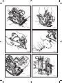
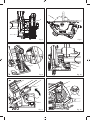
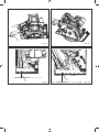
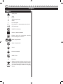
EWS1150RS EN FR DE ES IT NL PT DA SV FI NO RU PL CS HU RO LV LT ET HR SL SK EL TR 1150W 55MM CIRCULAR SAW SCIE CIRCULAIRE 55MM 1150W 1150W 55MM KREISSÄGE SIERRA CIRCULAR 55MM 1150W MOTOSEGA CIRCOLARE DA 1150W 55MM 1150W 55M CIRKELZAAGMACHINE SERRA CIRCULAR 55MM DE 1150W 1150W 55MM RUNDSAV CIRKELSÅG 55 MM/1150W 1150 W 55 MM PYÖRÖSAHA 1150 W 55 MM SIRKELSAG ЦИРКУЛЯРНАЯ ПИЛА, 55 ММ, 1150 ВТ PILARKA TARCZOWA 1150 W, 55 MM 1150 W 55MM ROTAČNÍ PILA 1150 W-OS 55 MM-ES KÖRFŰRÉSZ FERĂSTRĂU CIRCULAR 55 MM 1150 W 1150 W 55 MM RIPZĀĢIS 1150 W 55 MM DISKINIS PJŪKLAS KETASSAAG 55 MM 1150 W CIRKULAR 55 MM OD 1150 W 1150 W 55 MM KROŽNA ŽAGA 1150W 55 MM KOTÚČOVÁ PÍLA 1150W 55MM ΚΥΚΛΙΚΟΣ ΚΟΠΤΗΣ "1150W 55 MM DAIRE TESTERE USER’S MANUAL MANUEL D’UTILISATION BEDIENUNGSANLEITUNG MANUAL DE UTILIZACIÓN MANUALE D’USO GEBRUIKSHANDLEIDING MANUAL DE UTILIZAÇÃO BRUGERVEJLEDNING INSTRUKTIONSBOK KÄYTTÄJÄN KÄSIKIRJA BRUKSANVISNING РУКОВОДСТВО ПО ЭКСПЛУАТАЦИИ INSTRUKCJA OBSŁUGI NÁVOD K OBSLUZE HASZNÁLATI ÚTMUTATÓ MANUAL DE UTILIZARE LIETOTĀJA ROKASGRĀMATA NAUDOJIMO VADOVAS KASUTAJAJUHEND KORISNIČKI PRIRUČNIK UPORABNIŠKI PRIROČNIK NÁVOD NA POUŽITIE ΟΔΗΓΙΕΣ ΧΡΗΣΗΣ KULLANiM KILAVUZU 1 5 9 13 17 21 25 29 33 37 41 45 49 53 57 61 65 69 73 77 81 85 89 93 | FR TRADUCTION DES INSTRUCTIONS ORIGINALES | DE ÜBERSETZUNG DER ORIGINALANLEITUNG | ES TRADUCCIÓN DE LAS | IT TRADUZIONE DELLE ISTRUZIONI ORIGINALI | NL VERTALING VAN DE ORIGINELE INSTRUCTIES | PT TRADUÇÃO DAS INSTRUÇÕES ORIGINAIS | DA OVERSÆTTELSE AF DE ORIGINALE INSTRUKTIONER | SV ÖVERSÄTTNING AV DE URSPRUNGLIGA INSTRUKTIONERNA | FI ALKUPERÄISTEN OHJEIDEN SUOMENNOS | NO OVERSETTELSE AV DE ORIGINALE INSTRUKSJONENE | RU ПЕРЕВОД ОРИГИНАЛЬНЫХ ИНСТРУКЦИЙ | PL TŁUMACZENIE INSTRUKCJI ORYGINALNEJ | CS PŘEKLAD ORIGINÁLNÍCH POKYNŮ | HU AZ EREDETI ÚTMUTATÓ FORDÍTÁSA | RO TRADUCEREA INSTRUCŢIUNILOR ORIGINALE | LV TULKOTS NO ORIĢINĀLĀS INSTRUKCIJAS | LT ORIGINALIŲ INSTRUKCIJŲ VERTIMAS | ET ORIGINAALJUHENDI TÕLGE | HR PRIJEVOD ORIGINALNIH UPUTA | SL PREVOD ORIGINALNIH NAVODIL | SK PREKLAD ORIGINÁLNEHO NÁVODU | EL ΜΕΤΑΦΡΑΣΗ ΤΩΝ ΠΡΩΤΟΤΥΠΩΝ ΟΔΗΓΙΩΝ | TR ORIJINAL TALIMATLARIN TERCÜMESI EN ORIGINAL INSTRUCTIONS INSTRUCCIONES ORIGINALES 21 9 22 1 2 12 3 8 11 4 6 5 10 Fig. 1 Fig. 2 8 7 13 10 14 12 11 7 Fig. 3 Fig. 4 1 1 15 11 4 Fig. 5 Fig. 6 16 15 Fig. 7 Fig. 8 18 2 19 17 Fig. 9 Fig. 10 21 2 22 23 20 19 Fig. 11 Fig. 12 24 Fig. 13 25 Fig. 14 26 Fig. 15 Fig. 16 si EN FR DE ES IT NL PT DA SV FI NO RU PL CS HU RO LV LT ET HR SL SK EL TR English DESCRIPTION own cord. Contact with a “live" wire will also make exposed metal parts of the power tool “live" and shock the operator. 1. Spindle lock 2. Bevel adjustment lever 3. Edge guide lock screw 4. Base plate 5. Edge guide 6. Lower guard 7. Blade 8. Lower guard lever 9. Upper guard 10. Outer blade flange 11. Hex-head bolt 12. Wrench 13. Washer 14. Inner blade flange 15. Depth adjustment lever 16. Depth of cut 17. Depth pointer 18. Depth scale 19. Bevel scale 20. Bevel pointer 21. Lock-off trigger 22. Switch 23. Live tool indicator 24. Vacuum adapter 25. 0˚ bevel notch 26. 45° bevel notch When ripping always use a rip fence or straight edge guide. This improves the accuracy of cut and reduces the chance of blade binding. Always use blades with correct size and shape (diamond versus round) of arbour holes. Blades that do not match the mounting hardware of the saw will run eccentrically, causing loss of control. Use only blades specified in this manual, complying with EN 847-1. Never use damaged or incorrect blade washers or bolt. The blade washers and bolt were specially designed for your saw, for optimum performance and safety of operation. Causes and operator prevention of kickback: kickback is a sudden reaction to a pinched, bound or misaligned saw blade, causing an uncontrolled saw to lift up and out of the workpiece toward the operator; when the blade is pinched or bound tightly by the kerf closing down, the blade stalls and the motor reaction drives the unit rapidly back toward the operator; if the blade becomes twisted or misaligned in the cut, the teeth at the back edge of the blade can dig into the top surface of the wood causing the blade to climb out of the kerf and jump back toward the operator. Kickback is the result of saw misuse and/or incorrect operating procedures or conditions and can be avoided by taking proper precautions as given below. SPECIAL SAFETY RULES Do not use any abrasive wheels. DANGER Keep hands away from cutting area. Keep hands away from blade. Keep your second hand on auxiliary handle, or motor housing. If both hands are holding the saw, they cannot be cut by the blade. Maintain a firm grip with both hands on the saw and position your arms to resist kickback forces. Position your body to either side of the blade, but not in line with the blade. Kickback could cause the saw to jump backwards, but kickback forces can be controlled by the operator, if proper precautions are taken. Do not reach underneath the workpiece. The guard cannot protect you from the blade below the workpiece. When blade is binding, or when interrupting a cut for any reason, release the trigger and hold the saw motionless in the material until the blade comes to a complete stop. Never attempt to remove the saw from the work or pull the saw backward while the blade is in motion or kickback may occur. Investigate and take corrective actions to eliminate the cause of blade binding. Adjust the cutting depth to the thickness of the workpiece. Less than a full tooth of the blade teeth should be visible below the workpiece. Never hold piece being cut in your hands or across your leg. Secure the workpiece to a stable platform. It is important to support the work properly to minimize body exposure, blade binding, or loss of control. When restarting a saw in the workpiece, centre the saw blade in the kerf and check that saw teeth are not engaged into the material. If saw blade is binding, it may walk up or kickback from the workpiece as the saw is restarted. Hold power tool by insulated gripping surfaces only, when performing an operation where the cutting accessory may contact hidden wiring or its 1 EN FR DE ES IT NL PT DA SV FI NO RU PL CS HU RO LV LT ET HR SL SK EL TR English Support large panels to minimise the risk of blade pinching and kickback. Large panels tend to sag under their own weight. Supports must be placed under the panel on both sides, near the line of cut and near the edge of the panel. Blade Do not use dull or damaged blades. Unsharpened or improperly set blades produce narrow kerf causing excessive friction, blade binding and kickback. Use extra caution when making a "plunge cut" into existing walls or other blind areas. The protruding blade may cut objects that can cause kickback. 20 mm Blade size 170 mm 38 mm Bevel scale 0 - 45º ASSEMBLY INTENDED USE Sawing wood. Don’t use it for a purpose not intended. OPERATION ATTACHING THE BLADE See Figure 2-4. 1. Press and hold the spindle lock button. 2. Turn the hex-head bolt with a wrench until the spindle locks. 3. Loosen the hex-head bolt by turning the wrench anticlockwise. 4. Remove the hex-head bolt and the outer blade washer. 5. Retract the lower guard back with the lower guard lever as far as possible under the upper guard. 6. Attach the saw blade against the inner blade washer on the spindle. 7. Fit the outer blade washer and the hex-head bolt. 8. Tighten the hex-head bolt by turning the wrench clockwise. 9. After tightening the hex-head bolt, release the spindle lock button. NOTE: When the blade has been installed, make sure the spindle lock has been released by spinning the blade freely. SPECIFICATIONS Bore size 55 mm at 45º Be sure to disconnect the tool from the power supply before attaching or removing the saw blade. Be sure that the teeth of the saw blade are pointing upward at the front of the tool Always observe that the lower guard is covering the blade before placing saw down on bench or floor. An unprotected, coasting blade will cause the saw to walk backwards, cutting whatever is in its path. Be aware of the time it takes for the blade to stop after switch is released. 1150 W at 0º Wrench Lower guard should be retracted manually only for special cuts such as “plunge cuts" and “ compound cuts". Raise lower guard by retracting handle and as soon as blade enters the material, the lower guard must be released. For all other sawing, the lower guard should operate automatically. 5600 RPM 2.2 mm Parallel fence Check the operation of the lower guard spring. If the guard and the spring are not operating properly, they must be serviced before use. Lower guard may operate sluggishly due to damaged parts, gummy deposits, or a build-up of debris. No-load speed 12 T Width of cut STANDARD ACCESSORIES Check lower guard for proper closing before each use. Do not operate the saw if lower guard does not move freely and close instantly. Never clamp or tie the lower guard into the open position. If saw is accidentally dropped, lower guard may be bent. Raise the lower guard with the retracting handle and make sure it moves freely and does not touch the blade or any other part, in all angles and depths of cut. Input Teeth Saw blade SAFETY INSTRUCTIONS FOR SAWS WITH LOWER GUARD 230 V - 240 V 1.5 mm Cutting capacity Blade depth and bevel adjusting locking levers must be tight and secure before making cut. If blade adjustment shifts while cutting, it may cause binding and kickback. Voltage Thickness 50 Hz 2 EN FR DE ES IT NL PT DA SV FI NO RU PL CS HU RO LV LT ET HR SL SK EL TR English REMOVING THE BLADE 1. Press and hold the spindle lock button. 2. Turn the hex-head bolt with a wrench until the spindle locks. 3. Loosen the hex-head bolt by turning the wrench anticlockwise. 4. Remove the hex-head bolt and the outer blade washer. 5. Retract the lower guard back as far as possible under the upper guard. 6. Remove the saw blade. to avoid overloading the motor. CUTTING POSITION See Figure 15-16. When cutting a workpiece at 0°, use point "A" of the base plate line guide and move the saw along the pencilled line you have drawn. When cutting at 45°, use point "B". This line guide shows an approximate line of cut. Make a sample cut in scrap lumber to determine the actual line of cut. ADJUSTING THE DEPTH OF CUT CAUTION See Figure 5-9. 1. Loosen the depth adjustment knob. 2. Slide the base plate to the desired depth using the depth adjustment knob and then retighten securely. NOTE: The depth of cut can be determined by the depth scale or by measuring the distance by which the blade protrudes from the base plate. When ripping, the rip fence should only touch the workpiece slightly. Do not force. LIVE TOOL INDICATOR This tool features a live tool indicator which illuminates as soon as the tool is connected to the supply. This warns the user that the tool is connected and will operate when the switch is pressed. ADJUSTING THE ANGLE See Figure 10-11. 1. Set the cutting angle to any position between 0° and 45°. 2. Loosen the bevel adjustment knob at the front of the tool and move the base plate to the desired angle using the bevel scale. 3. Retighten the bevel adjustment knob. MAINTENANCE After use, check the tool to make sure that it is in top condition. It is recommended that you take this tool to a Ryobi Authorized Service Center for a thorough cleaning and lubrication at least once a year. SWITCH See Figure 12. This tool is started and stopped by squeezing and releasing the trigger switch. To prevent the tool from being started accidentally, the trigger can only be operated if the safety button is depressed first. The safety button can be depressed with the thumb leaving the other fingers free to squeeze the trigger switch. It is not necessary to maintain pressure on the safety button once the trigger switch has been depressed. Do not make any adjustments while the motor is running. Always disconnect the power cord from the socket before changing removable or expendable parts before lubricating or working on the unit. Keep handles dry, clean and free from oil and grease. If the power supply cord is damaged, it must be replaced only by the manufacturer or by an authorized service center to avoid risk. Contact authorized service center. WARNING OPERATION For greater safety and reliability, all repairs should be performed by an authorised Ryobi Service Centre. DANGER Keep hands away from the cutting area when operating the tool. Keep the cord away from the cutting area and position it so that it will not get caught on the workpiece during the cutting operation. ENVIRONMENTAL PROTECTION Recycle raw materials instead of disposing of as waste. The machine, accessories and packaging should be sorted for environmental-friendly recycling. When cutting, use steady and even pressure in order to obtain a uniform cut; do not force. Cut at a speed suited to the workpiece. Cut slowly if the workpiece is hard. Inspect the saw blade frequently and replace or sharpen it if dull, 3 EN FR DE ES IT NL PT DA SV FI NO RU PL English SYMBOLS Safety Alert V Volts Hz Hertz Alternating Current W Watts nₒ No-load speed min־¹ Revolutions or reciprocations per minute CE Conformity GOST-R conformity Class II, double insulated Please read the instructions carefully before starting the machine. Wear eye protection Wear ear protection Wood Do not cut metals Width of cut Ø Diameter Waste electrical products should not be disposed of with household waste. Please recycle where facilities exist. Check with your local authority or retailer for recycling advice. 4 CS HU RO LV LT ET HR SL SK EL TR