1
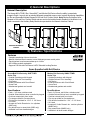
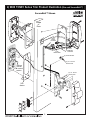
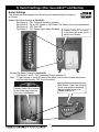
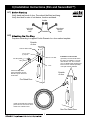
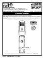
Installation Instructions
for 9800 TCNE1 Series Trim by ED5200N (S) (A)
and 9M800 TCNE1 Series Trim by ED5600N (A) with
Rim, SecureBolt™, and Mortise Exit Devices
FM242B 12/08 (617417610)
Please read these instructions carefully to prevent missing important Steps.
Please Note: Improper installations may result in damage to the lock and void the factory warranty.
Important: The accuracy of the door preparation is critical for proper functioning and security of this trim.
Misalignment can cause premature wear and a lessening of security.
1
2
3
4
5
6
7
8
9
*
0
#
CAUTION
DOOR MUST REMAIN OPEN
DURING INSTALLATION.
USE DOOR STOP.
TEST
FOR PROPER
OPERATION
BEFORE
CLOSING
DOOR
For installation assistance contact Corbin Russwin Inc. at 1-800-810-WIRE (9473).
Table of Contents
Page
1)
2)
3)
4)
5)
6)
Warning
General Description
Features / Specifications
Rim & SecureBolt™ TCNE1 Series Product Illustration
Switch Settings (Rim & SecureBolt™)
Installation Instructions
1
2
2
3
4
5 - 11
7)
Mortise TCNE1 series Product Illustration
12
8)
Operational Check
20
6.1)
6.2)
6.3)
6.4)
6.5)
6.6)
6.7)
Before Starting
Attaching the Fire Stop Plate
Trim Assembly Instructions
Installation of Outside Trim and Exit Device
Installation of Outside Keypad Escutcheon
Installation of Inside Controller Escutcheon and Electrical Connections
Cover Installation
7.1)
7.2)
7.3)
7.4)
7.5)
7.6)
7.7)
Before Starting
Attaching the Fire Stop Plate
Installation of Mortise Lock
Installation of Outside Trim and Exit Device
Installation of Cylinder and Outside Keypad Escutcheon
Installation of Inside Controller Escutcheon and Electrical Connections
Cover Installation
5
5
6
7-8
9
10
11
13
13
14
15 - 16
17
18
19
1) Warning
Changes or modifications to this unit not expressly approved by the party responsible
for compliance could void the user's authority to operate the equipment.
This device complies with Part 15 of the FCC Rules. Operation is subject to the following two
conditions: (1) this device may not cause harmful interference, and (2) this device must accept any
interference received, including interference that may cause undesired operation.
Note: This equipment has been tested and found to comply with the limits for a Class B digital
device, pursuant to Part 15 of the FCC Rules. These limits are designed to provide reasonable
protection against harmful interference in a residential installation. This equipment generates, uses
and can radiate radio frequency energy and if not installed and used in accordance with the
instructions, may cause harmful interference to radio communications. However, there is no
guarantee that the interference will not occur in a particular installation. If this equipment does
cause harmful interference to radio or television reception, which can be determined by turning
the equipment off and on, the user is encouraged to try to correct the interference by one or more
of the following measures:
•
•
•
•
Reorient or relocate the receiving antenna
Increase the separation between the equipment and receiver
Connect the equipment into an outlet on a circuit different from that to which the receiver is connected
Consult the dealer or an experienced TV technician for help
This Class B digital apparatus complies with Canadian ICES-003.
1
General Description
2) General Descriptions
The Access 800 ® TCNE1 Rim, SecureBolt™ and Mortise Exit Device offers the ability to seamlessly
integrate Grade 1 security into an existing Wiegand compatible access control system. Monitoring capabilities
for Rim and SecureBolt include Request to Exit and Door Position Switch. Note: Mortise Exit devices offer
Request to Exit and Door Position Switch and can monitor the latchbolt and/or Deadbolt of the Mortise Lock
when connected to the Auxiliary Relay Module incorporated into the Network Interface Cabinet.
Access
Control
Panel
*
*
*
*
NETWORK INTERFACE
CABINET
3) Features / Specifications
Features
• Complete monitoring of doors from locks
• Network Interface board connects to most third party access control points
• Panel interface board accommodates up to 4 locks
• HID 125khz proximity credentials
• Supports Fail-Safe and Fail-Secure 24VDC Solenoid Locking Devices
Items Supplied with Exit Device
Items included with ED5200N (S) (A) Rim or
SecureBolt Exit Device by 9800 TCNE1
Series Trim
• Outside Escutcheon with Keypad
• Outside Solenoid Trim Assembly
• Exit Device
• Inside Escutcheon with Circuit Board
• Screw Pack
• Weatherseal gaskets and conduit
Items included with ED5600N (A) Series
Mortise Exit Device by 9M800 TCNE1
Series Trim
• Outside Escutcheon with Keypad
• Outside Solenoid Trim Assembly
• Exit Device
• Inside Escutcheon with Circuit Board
• Screw Pack
• Weatherseal gaskets and conduit
Specifications
Specifications
• Latch – 3/4" throw, stainless steel
• Outside Solenoid driven lever controlled by keypad
• Push bar retracts latch from inside
• Fire stop provided for fire rated doors
• Exit devices furnished for 1-3/4" - 2 1/4" doors
• UL Listed
• Accepts all Corbin Russwin Inc. rim cylinders
(9803 only)
• Key allows lever to retract latch (9803 only)
• Available in all lever handle designs
• Latch 3/4" throw, anti-friction, stainless steel
• Outside Solenoid driven lever controlled by keypad
• Push bar retracts latch from inside
• Fire stop provided for fire rated doors
• Exit devices furnished for 1 3/4" – 2 1/4" doors
• UL Listed
• Accepts all Corbin Russwin Inc. mortise cylinders
(9M805 only)
• Key retracts latch (9M805 only)
• Available in all lever handle designs
2
4) 9800 TCNE1 Series Trim Product Illustration (Rim and SecureBolt™)
SecureBolt™ Shown
Inside
of
Door
8 Pin
Molex
Doorwire
2 Pin
Molex REX
Ground
Wire
2 Pin
Methode
Solenoid
(2) Finish Washers
(2) 1/4 - 20 Oval
Head Screws
Tailpiece
must be
in vertical
position
(2) 1/4 - 20 Pan
Head Screws
Trim
Gasket
Cover
3
5) Switch Settings (Rim, SecureBolt™ and Mortise)
Switch Settings
This device has been shipped from the factory with switch settings configured
as follows:
Reader Dip-Switch Settings at Switch S1:
Dip-Switch 4 – ON Solenoid Operation selected
Dip-Switch 5 – ON or OFF based on Fail Safe or Fail Secure per order requirements
Dip-Switch 6 – OFF Red LED
Dip-Switch 7 – OFF Tamper Input Select Disabled
Reader Switch S1 is located
in the lower left corner on the
back of the Reader.
Reader Dip-Switch Settings at Switch S2:
Dip-Switch 1 and 2 – OFF, indicating Reader Address #1
Note: To gain access to switch S2 remove the black cover from the inside escutcheon
with the High Security T20 Torx bit provided.
Both Switch 1 and 2 are shown
in the open position indicating
that the reader is set to be
Reader address #1.
Reader Switch S2 is located
in the lower right corner on
the front of the Reader.
4
6) Installation Instructions (Rim and SecureBolt™)
6.1)
Verify hand and bevel of door. Door should be fitted and hung.
Verify box label for size of exit device, function and hand.
Inside
Left Hand
Reverse
"LHR"
Right Hand
Reverse
"RHR"
Outside
6.2)
Prep door according to supplied Corbin Russwin Inc. door marker template.
Outside
of door
Hole for ribbon cable
7/8"
1/8" Dia. holes
(2) required
CL of 1-1/2" Dia.
Fire Stop Plate
Slot
1-1/2"
Attach Fire Stop Plate
Using self tapping screws
#8x1/2" long for wood and
metal doors
Installation of the Conduit
(provided) is recommended when
the device is installed in a non fire
rated exterior door. The conduit is
part of a Weatherseal Gasketing Kit.
This kit can be ordered separately,
order part number 794F909.
Outside
of door
R
FO
O
USE N FIRE
D
O
OR
NO
T
Fire Rated Door
Install conduit half with recessed
panel "Not For Use On Fire Door"
visible from outside of door.
Non Fire Rated Door
5
6) Installation Instructions (Rim and SecureBolt™)
6.3)
1. Check cylinder components.
NOTE: Cylinders longer than 1-1/8" (29mm) will require collars.
Refer to Cylinder Collar Chart below.
2. When required, cut cylinder tailpiece.
Correct length is 1/16" to 3/16" (2 to 5mm) beyond cylinder housing cam.
3. Assemble cylinder.
Insert cylinder housing prongs into matching notches of escutcheon.
Pass cylinder tailpiece thru cylinder collar (when required) and slot
in cylinder cam. Fasten cylinder in escutcheon recess or collar
using (2) mounting screws.
(DO NOT OVER TIGHTEN SCREWS).
Cylinder
Ta ilpiece
Rim Cylinder
(2) Cylinder Mounting Screws.
Supplied with cylinder
Cylinder Collar
(when required)
Cylinder Housing Cam
Cylinder Collar Chart
Cylinder length
Collar
1-1/8" (29)
None
1-1/4" (32)
422F88*
1-1/2" (38)
686F98*
* Specify Finish
Cam must be positioned as shown
when cylinder tailpiece is assembled
Escutcheon Assembly
Lever is handed, LHR (shown).
NOTE: Lever Return Spring is handed.
Hand of trim cannot be changed without
correct spring.
Lever Return Spring handing can be identified
by the color of the spring:
LHR, part number 651F618 (Red)
RHR, part number 651F628 (Blue)
6
6) Installation Instructions (Rim and SecureBolt™)
6.4) Installation of Outside Trim and Exit Device
Outside Trim Assembly
1. For exterior door applications, it is recommended that the Trim Gasket
(provided) be applied as shown below.
2. Route the 2 pin REX (Request to Exit) connector harness into the Trim Assembly cavity in
the door and up thru the door and out the 1/2” diameter Hole “C”.
3. Route the Trim Assembly 2 pin connector of the Solenoid wire harness into the trim
assembly cavity in the door and out the 1/2” diameter hole “C”. Be careful not to pinch any
wire harness wires.
4. When mounting trim, lift tailpiece to pass through hole on device side. Be sure tailpiece is
in vertical position.
5. Fasten trim assembly through holes “A” using (2) 1/4” – 20 oval head screws and (2) finish
washers. Finger tight only!
CAUTION
DOOR MUST REMAIN OPEN
DURING INSTALLATION.
USE DOOR STOP.
Trim Assembly
Solenoid Wire
Harness
Inside
of
Door
8 Pin
Molex
Doorwire
2 Pin
Molex REX
C
A
Tailpiece
must be
in vertical
position
(2) Finish Washers
(2) 1/4 - 20 Oval
Head Screws
2 Pin
Methode
Solenoid
B
(2) 1/4 - 20 Pan
Head Screws
Trim
Gasket
B
A
TRIM GASKET APPLICATION:
Peel off the adhesive protective paper
from gasket. Feed Trim assembly solenoid
wire harness through gasket opening as
shown and firmly press gasket to
escutcheon, aligning edge of gasket with
the edge of the escutcheon.
7
Cover
6) Installation Instructions (Rim and SecureBolt™)
6.4) Installation of Outside Trim and Exit Device
Outside Trim Assembly
1. Seal device against door being careful to align vertical trim tailpiece to
engage with cross hole of device cam.
2. Fasten device to trim assembly through holes “B” using (2) 1/4 – 20 pan head screws.
3. Follow instructions packed with device to secure device to door. Tighten all screws.
CAUTION
DOOR MUST REMAIN OPEN
DURING INSTALLATION.
USE DOOR STOP.
Trim Assembly
Solenoid Wire
Harness
Inside
of
Door
8 Pin
Molex
Doorwire
2 Pin
Molex REX
C
A
Tailpiece
must be
in vertical
position
(2) Finish Washers
(2) 1/4 - 20 Oval
Head Screws
2 Pin
Methode
Solenoid
B
(2) 1/4 - 20 Pan
Head Screws
Trim
Gasket
B
A
TRIM GASKET APPLICATION:
Peel off the adhesive protective paper
from gasket. Feed Trim assembly solenoid
wire harness through gasket opening as
shown and firmly press gasket to
escutcheon, aligning edge of gasket with
the edge of the escutcheon.
8
Cover
6) Installation Instructions (Rim and SecureBolt™)
6.5) Installation of Outside Keypad Escutcheon
1. For exterior door applications, it is recommended that the gaskets provided
be applied as shown. The gaskets may be used as a seal between the escutcheon
and the door surfaces.
2a. For fire rated devices, feed keypad ribbon cable/connector and ground wire from
outside of door through fire stop plate and hole in door.
2b. For non fire rated exit devices, feed keypad ribbon cable/connector and ground wire
through the door.
3. Place escutcheon against door surface.
GASKET APPLICATION:
Peel off the adhesive protective paper from
gasket. Feed Keypad ribbon cable and ground
wire through gasket opening as shown and firmly
press gasket to escutcheon, aligning edge of
gasket with the edge of the escutcheon.
Outside
Of
Door
Keypad Ribbon Cable
Fire Stop Plate
Ground Wire
9
6) Installation Instructions (Rim and SecureBolt™)
6.6) Installation of Inside Controller Escutcheon and
Electrical Connections
1. For exterior door applications it is recommended that the gaskets provided
be applied as shown.
2. Remove black cover from the escutcheon with High Security T20 Torx bit provided.
3. Connect the Keypad ribbon cable to the terminal on the controller.
4. Connect the ground wire coming from the Keypad to the insulated spade lug receptacle
coming off the Controller Harness.
5. Complete making all the connections by matching up the connectors being certain all the
connections are secure.
6. Feed excess wire through the inside of the door hole and into outside Keypad escutcheon
cavity, being careful not to pinch wires. Gather excess wire from the controller and position
the excess into the controller escutcheon, being careful not to pinch wires.
7. Insert (2) #10-24 screws through top and bottom of inside escutcheon and thread into
outside escutcheon. Straighten escutcheons and tighten securely, being careful to avoid
pinching wires.
CAUTION
GASKET APPLICATION:
Peel off the adhesive protective paper from gasket.
Feed all wires and harnesses through gasket opening
as shown and firmly press gasket to escutcheon,
aligning edge of gasket with edge of escutcehon.
Controller
Escutcheon
Keypad Ribbon
Cable
8 Pin
Molex
Doorwire
Black
Cover
Ground
Wire
Security Screw
T20 Torx Bit
Keypad harness
(ribbon cable)
1
2
52-0624B
23
24
J3
NOT
(USED
(
J2
J1
TB1
J3
NOT
(USED
(
TB1
10
Ground Terminal
E1 GROUND TAB
S1
52-0624B
2 Pin
Molex REX
2 Pin
Methode
Solenoid
E1 GROUND TAB
Inside
of Door
DOOR MUST REMAIN OPEN
DURING INSTALLATION.
USE DOOR STOP.
J2
J1
6) Installation Instructions (Rim and SecureBolt™)
6.7) Cover Installation
1. Attach cover to inside controller escutcheon making sure to line up tabs
with retaining slots in the cover. Secure with security screw using T20 bit.
CAUTION
DOOR MUST REMAIN OPEN
DURING INSTALLATION .
USE DOOR STOP.
Tabs
Retaining Slots
TEST
FOR PROPER
OPERATION
BEFORE
CLOSING
DOOR
Controller
Escutcheon
Black
Cover
Security Screw
T20 Torx Bit
11
7) 9M800 TCAC1 Series Trim Product Illustration (Mortise)
8 Pin
Molex
Doorwire
2 Pin
Molex REX
“A”
Solenoid
Wire
Harness
“B”
“A”
“B”
12
Ground
Wire
2 Pin
Methode
Solenoid
7) Installation Instructions (Mortise)
7.1) Before Starting
This device is handed because of the mortise lock and trim assembly
being handed.
Door should be fitted and hung. Verify box label for size of exit device,
function and hand.
Inside
Left Hand
Reverse
"LHR"
Outside
Right Hand
Reverse
"RHR"
7.2) Attaching the Fire Stop Plate
Prep door according to supplied Corbin Russwin Inc. door marker template.
Outside
of Door
7/8"
1/8" Dia. holes
(2) required
Fire Stop Plate
CL of 1-1/2 Dia
.
1-1/2
The Optional Conduit is available
for Non Fire rated doors to provide
weather protection for exterior door
applications. It is included in the M99
Weatherseal Gasketing Kit when
ordered with the device. If ordered
separately, order part number
794F909.
Slot
Attach Fire Stop Plate
using self tapping screws
#8x1/2" long for wood and
metal doors
R
FO
O
USE N FIRE
D
O
OR
NO
T
Fire Rated Door
Outside
of Door
Install conduit half with recessed
panel "Not For Use On Fire Door"
visible from outside of door.
Non Fire Rated Door
13
7) Installation Instructions (Mortise)
7.3) Install Mortise Lock
1. Feed Solenoid wire from Mortise Lock into Mortise cavity and up
through the 1/2 diameter hole “C”.
2. While sliding Mortise Case into door prep, pull the Solenoid wire from the Mortise
Case out through “C” so that this wire does not get trapped behind the Mortise Case
3. Slide Mortise Lock into door and loosely fasten with (2) flat head combination screws.
Inside
of Door
8 Pin
Molex
Doorwire
“C”
2 Pin
Molex
REX
2 Pin
Methode
Solenoid
Mortise Lock
(2) #12x1" long flat
head combination
screw.
14
7) Installation Instructions (Mortise)
7.4) Installation of Outside Trim and Exit Device
Outside Trim Assembly
1. For exterior door applications, it is recommended that the gaskets
provided be applied as shown.
2. Route the 2 pin REX (Request to Exit) connector harness into the Trim Assembly
cavity in the door and up thru the door and out the 1/2” diameter Hole “C”.
3. Route the Trim Assembly 2 pin connector of the Solenoid wire harness into the trim
assembly cavity in the door and out the 1/2” diameter hole “C”. Be careful not to
pinch any wire harness wires.
4. Mount trim assembly to door through holes “A” using (2) 1/4” – 20 oval head
screws and (2) finish washers. Finger tight only!
TRIM GASKET APPLICATION:
Peel off the adhesive protective paper
from gasket. Feed Trim assembly solenoid
wire harness through gasket opening as
shown and firmly press gasket to
escutcheon, aligning edge of gasket with
the edge of the escutcheon.
8 Pin
Molex
Doorwire
2 Pin
Molex REX
2 Pin
Methode
Solenoid
“A”
“B”
Solenoid
Wire Harness
Trim
Gasket
Cover
“A”
“B”
Device
Finger
15
(2) 1/4-20
Pan Head Screws
7) Installation Instructions (Mortise)
7.4) Installation of Outside Trim and Exit Device
Exit Device
1. Seat device against door. NOTE: Device finger must engage
latch bolt lever through slot in door and lock case/cover.
2. Fasten device to trim assembly through holes “B” using (2) 1/4 - 20 pan head
screws.
3. Follow instructions packed with device to secure device to door. Tighten all screws.
TRIM GASKET APPLICATION:
Peel off the adhesive protective paper
from gasket. Feed Trim assembly solenoid
wire harness through gasket opening as
shown and firmly press gasket to
escutcheon, aligning edge of gasket with
the edge of the escutcheon.
8 Pin
Molex
Doorwire
2 Pin
Molex
REX
2 Pin
Methode
Solenoid
“A”
“B”
Solenoid
Wire Harness
Trim
Gasket
Cover
“A”
“B”
Device
Finger
16
(2) 1/4-20
Pan Head Screws
7) Installation Instructions (Mortise)
7.5) Installation of Cylinder and Outside Keypad Escutcheon
Cylinder Installation
Note: For devices without cylinders, skip this section.
1. Back cylinder set screw out of Mortise Lock.
2. Insert cylinder through trim assembly and thread into Mortise Lock until cylinder is flush with
escutcheon. Keyway should be vertical with plug toward lever.
3. Tighten cylinder set screw.
4. Assemble Mortise Lock armor front with (2) screws.
5. Tighten all screws for lock, trim assembly and exit device.
Outside Keypad Escutcheon
1. For exterior applications, it is recommended that the Trim Gasket (provided) be applied
as shown.
2a. For fire rated devices, feed keypad ribbon cable/connector and ground wire from outside of
door through fire stop plate and hole in door.
2b. For non fire rated exit devices, feed keypad ribbon cable/connector and ground wire through
hole in door.
3. Place escutcheon against door surface.
GASKET APPLICATION:
Peel off the adhesive protective paper from
gasket. Feed Keypad ribbon cable and ground
wire through gasket opening as shown and firmly
press gasket to escutcheon, aligning edge of
gasket with the edge of the escutcheon.
Gasket
(optional)
Outside
Of
Door
Keypad Ribbon Cable
Fire Stop Plate
Ground Wire
Cylinder Set Screw
Armor
Front
17
7) Installation Instructions (Mortise)
7.6) Installation of Inside Controller Escutcheon and
Electrical Connections
1. For exterior door applications it is recommended that the gaskets provided
be applied as shown.
2. Remove black cover from the escutcheon with High Security T20 Torx bit provided.
3. Connect the Keypad ribbon cable to the terminal on the controller.
4. Connect the ground wire coming from the Keypad to the insulated spade lug receptacle
coming off the Controller Harness.
5. Complete making all the connections by matching up the connectors being certain all the
connections are secure.
6. Feed excess wire through the inside of the door hole and into outside Keypad escutcheon
cavity, being careful not to pinch wires. Gather excess wire from the controller and position
the excess into the controller escutcheon, being careful not to pinch wires.
7. Insert (2) #10-24 screws through top and bottom of inside escutcheon and thread into
outside escutcheon. Straighten escutcheons and tighten securely, being careful to avoid
pinching wires.
CAUTION
GASKET APPLICATION:
Peel off the adhesive protective paper from gasket.
Feed all wires and harnesses through gasket opening
as shown and firmly press gasket to escutcheon,
aligning edge of gasket with edge of escutcehon.
Controller
Escutcheon
Keypad Ribbon
Cable
8 Pin
Molex
Doorwire
Black
Cover
Ground
Wire
Security Screw
T20 Torx Bit
Keypad harness
(ribbon cable)
1
2
52-0624B
23
24
J3
NOT
(USED
(
J2
J1
TB1
J3
NOT
(USED
(
TB1
18
Ground Terminal
E1 GROUND TAB
S1
52-0624B
2 Pin
Molex REX
2 Pin
Methode
Solenoid
E1 GROUND TAB
Inside
of Door
DOOR MUST REMAIN OPEN
DURING INSTALLATION.
USE DOOR STOP.
J2
J1
6) Installation Instructions (Mortise)
7.7) Cover Installation
1. Attach cover to inside controller escutcheon making sure to line up tabs with
retaining slots in the cover. Secure with security screw using T20 bit.
CAUTION
DOOR MUST REMAIN OPEN
DURING INSTALLATION .
USE DOOR STOP.
Tabs
Retaining Slots
TEST
FOR PROPER
OPERATION
BEFORE
CLOSING
DOOR
Controller
Escutcheon
Black
Cover
Security Screw
T20 Torx Bit
19
7) Operational Check (Rim, SecureBolt™, and Mortise)
1. For exit devices without cylinder override trims, go to Step 4 below.
2. For Rim and SecureBolt exit devices with 9803 Series cylinder override trims:
a. Insert key into cylinder and rotate.
b. While holding key in rotated position, operate outside lever to retract latch.
c. Key should rotate freely and outside lever should retract latch.
3. For Mortise exit devices with 9M805 Series cylinder override trims:
a. Insert key into cylinder and rotate.
b. Key should rotate freely and retract latch.
4. Depress exit device pushpad to retract latch.
CAUTION
DOOR MUST REMAIN OPEN
DURING INSTALLATION.
USE DOOR STOP.
TEST
FOR PROPER
OPERATION
BEFORE
CLOSING
DOOR
END OF INSTALLATION INSTRUCTIONS
Corbin Russwin, Inc.
225 Episcopal Road
Berlin, CT 06037-4004
www.corbinrusswin.com
Technical Product Support:
Corbin Russwin, Inc.
Phone 800-810-WIRE (9493)
Canada:
ASSA ABLOY Door Security Solutions Canada
160 Four Valley Drive
Vaughan, ON L4K 4TG
www.assaabloycanadadss.ca
Copyright © 2008 Corbin Russwin, Inc.,
an ASSA ABLOY Group company. All rights reserved.
Reproduction in whole or in part without the express
written permission of Corbin Russwin, Inc. is prohibited.
20