1
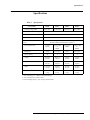
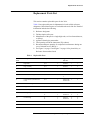
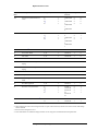
Agilent Technologies
382A Variable Attenuator
Operating and Service
Manual
Agilent Part Number: 00382-90037
Printed in USA
Print Date: July 2001
Supersedes: February 2001
Notice
The information contained in this document is subject to change without
notice.
Agilent Technologies makes no warranty of any kind with regard to this
material, including, but not limited to, the implied warranties of
merchantability and fitness for a particular purpose. Agilent Technologies
shall not be liable for errors contained herein or for incidental or
consequential damages in connection with the furnishing, performance, or
use of this material.
Agilent Technologies assumes no responsibility for the use or reliability of
its software on equipment that is not furnished by Agilent Technologies.
This document contains proprietary information which is protected by
copyright. All rights are reserved. No part of this document may be
photocopied, reproduced, or translated to another language without prior
written consent of Agilent Technologies.
RESTRICTED RIGHTS LEGEND
Use, duplication, or disclosure by the U.S. Government is subject to
restrictions as set forth in subparagraph (c)(1)(ii) of the Rights in Technical
Data and Computer Software clause at DFARS 252.227-7013 for DOD
agencies, and subparagraphs (c)(1) and (c)(2) of the Commercial Computer
Software Restricted Rights clause at FAR 52.227-19 for other agencies.
Agilent Technologies, Inc.
1400 Fountaingrove Parkway
Santa Rosa, CA 95403-1799, U.S.A.
© Copyright Agilent Technologies, Inc. 2000, 2001
ii Agilent 382A Operating And Service Manual
What You’ll Find In This Manual…
•
•
•
•
•
Overview, page 1
Specifications, page 3
Operation, page 4
Maintenance, page 17
Replacement Parts List, page 27
Agilent 382A Operating And Service Manual iii
Warranty
Custom systems are warranted by contractual agreement between Agilent
Technologies and the customer.
Certification
Agilent Technologies, Inc., certifies that this product met its published
specifications at the time of shipment from the factory. Agilent Technologies
further certifies that its calibration measurements are traceable to the
United States National Institute of Standards and Technology (NIST,
formerly NBS), to the extent allowed by the Institute’s calibration facility,
and to the calibration facilities of other International Standards
Organization members.
Warranty
THE MATERIAL CONTAINED IN THIS DOCUMENT IS PROVIDED
“AS IS,” AND IS SUBJECT TO BEING CHANGED, WITHOUT
NOTICE, IN FUTURE EDITIONS. FURTHER, TO THE MAXIMUM
EXTENT PERMITTED BY APPLICABLE LAW, AGILENT DISCLAIMS
ALL WARRANTIES, EITHER EXPRESS OR IMPLIED WITH REGARD
TO THIS MANUAL AND ANY INFORMATION CONTAINED
HEREIN, INCLUDING BUT NOT LIMITED TO THE IMPLIED
WARRANTIES OF MERCHANTABILITY AND FITNESS FOR A
PARTICULAR PURPOSE. AGILENT SHALL NOT BE LIABLE FOR
ERRORS OR FOR INCIDENTAL OR CONSEQUENTIAL DAMAGES
IN CONNECTION WITH THE FURNISHING, USE, OR
PERFORMANCE OF THIS DOCUMENT OR ANY INFORMATION
CONTAINED HEREIN. SHOULD AGILENT AND THE USER HAVE A
SEPARATE WRITTEN AGREEMENT WITH WARRANTY TERMS
COVERING THE MATERIAL IN THIS DOCUMENT THAT CONFLICT
WITH THESE TERMS, THE WARRANTY TERMS IN THE SEPARATE
AGREEMENT WILL CONTROL.
Assistance
Product maintenance agreements and other customer assistance agreements
are available for Agilent Technologies products.
For assistance, call your local Agilent Technologies Sales and Service
Office (refer to “Service and Support” on page v).
iv Agilent 382A Operating And Service Manual
Service and Support
Any adjustment, maintenance, or repair of this product must be performed
by qualified personnel. Contact your customer engineer through your local
Agilent Technologies Service Center. You can find a list of local service
representatives on the Web at:
http://www.agilent.com/find/assist
Click on “Contact Us” and select your country.
If you do not have access to the Internet, one of these centers can direct you
to your nearest Agilent Technologies representative:
United States
(800) 403-0801
Canada
(877) 429-9969
Europe
(41 22) 780.6111 (Switzerland)
(33 1) 69 82 66 66 (France)
(49 7031) 464-6222 (Germany)
(44 188) 9696622 (Great Britain)
Japan
0120-32-0119
Latin America
(11) 7297-3700 (Brazil)
Australia/New
Zealand
1-800-802-540 (Australia)
0800-738-378 (New Zealand)
Asia-Pacific
080-047-669
Agilent 382A Operating And Service Manual v
Safety and Regulatory Information
Review this product and related documentation to familiarize yourself with
safety markings and instructions before you operate the instrument. This
product has been designed and tested in accordance with international
standards.
WARNING
The WARNING notice denotes a hazard. It calls attention to a
procedure, practice, or the like, that, if not correctly performed or
adhered to, could result in personal injury. Do not proceed beyond a
WARNING notice until the indicated conditions are fully understood
and met.
CAUTION
The CAUTION notice denotes a hazard. It calls attention to an operating
procedure, practice, or the like, which, if not correctly performed or adhered
to, could result in damage to the product or loss of important data. Do not
proceed beyond a CAUTION notice until the indicated conditions are fully
understood and met.
Instrument Markings
!
When you see this symbol on your instrument, you should refer to the
instrument’s instruction manual for important information.
This symbol indicates hazardous voltages.
The laser radiation symbol is marked on products that have a laser output.
This symbol indicates that the instrument requires alternating current (ac)
input.
The CE mark is a registered trademark of the European Community. If it is
accompanied by a year, it indicates the year the design was proven.
The CSA mark is a registered trademark of the Canadian Standards
Association.
vi Agilent 382A Operating And Service Manual
1SM1-A
This text indicates that the instrument is an Industrial Scientific and Medical
Group 1 Class A product (CISPER 11, Clause 4).
This symbol indicates that the power line switch is ON.
This symbol indicates that the power line switch is OFF or in STANDBY
position.
This product complies with the WEEE Directive (2002/96/EC)
marking requirements. The affixed label indicates that you must not
discard this electrical/ electronic product in domestic household
waste.
Product Category: With reference to the equipment types in the
WEEE Directive Annex I, this product is classed as a "Monitoring
and Control instrumentation" product.
Do not dispose in domestic household waste .
To return unwanted products, contact your local Agilent office,
or see http://www.agilent.com/environment/product/ for more
information .
Safety Earth Ground
Before Applying
Power
This is a Safety Class I product (provided with a protective
earthing terminal). An uninterruptible safety earth ground must
be provided from the main power source to the product input
wiring terminals, power cord, or supplied power cord set.
Whenever it is likely that the protection has been impaired, the
product must be made inoperative and secured against any
unintended operation.
Verify that the product is configured to match the available main power
source as described in the input power configuration instructions in this
manual. If this product is to be powered by autotransformer, make sure the
common terminal is connected to the neutral (grounded) side of the ac power
supply.
Agilent 382A Operating And Service Manual vii
This page is intentionally left blank.
viii Agilent 382A Operating And Service Manual
Overview
The Agilent Technologies 382A variable precision attenuators are designed
for use in waveguide systems operating in the 3.95 to 40.0 GHz range. Each
model of the 382A series provides calibrated attenuation from zero to 50 dB
at any frequency within the rated waveguide band.
Attenuation is read directly on the dial. Residual attenuation (at zero setting)
is less than 1 dB over the waveguide range. Backlash is less than 0.3 dB at
50 dB. The SWR is low and variation of phase with setting is practically
negligible.
Initial Inspection
Mechanical Check
If damage to the shipping carton is evident, ask that the carrier's agent be
present when the instrument is unpacked. Inspect the instrument for
mechanical damage such as scratches, dents or broken knobs. Also check the
cushioning material for signs of severe stress (compacting).
Performance Check
The electrical performance of the 382A should be verified as soon as
possible after receipt. A performance check suitable for incoming inspection
is provided in “Performance Test” on page 7.
Claim For Damage
If the 382A is mechanically damaged or fails to meet specifications on
receipt, notify the carrier and the nearest Agilent Technologies office
immediately. (Refer to “Service and Support” on page v.) Retain the
shipping carton and the padding material for the carrier’s inspection.
Handling
Care of Flanges
Take care to prevent damage to the face of the coupling flanges. Any scoring
of the mating surfaces tends to increase the separation of the flange faces and
will cause increased leakage and loss, particularly where a current maximum
and voltage minimum occur at the flange. When storing the 382A, be sure to
replace the flange covers to preclude damage to the flanges.
Avoid Vertical Shock
When shipping or handling these attenuators in a manner in which will
subject it to shocks in a vertical plane, always set the attenuation dial to zero.
With the dial at zero, danger is minimized that vertical shocks will cause the
attenuator flag to move downward, releasing tension on the drive cable.
Agilent 382A Operating and Service Manual
1
Overview
When the tension is released, the drive cable can jump out of the grooved
portion of the drum, in which case the flag will be positioned approximately
half way between the scales. If this should occur, the trouble is easily
remedied: remove the cover and slip the cable back into its groove on the
drum. The accuracy of the attenuator will not be affected in any way.
2 Agilent 382A Operating and Service Manual
Specifications
Specifications
Table 1
Specifications
Characteristic
Frequency range (GHz)
X382A
P382A
K382A
R382A
8.2 to 12.4
12.4 to 18.0
18.0 to 26.5
26.5 to 40.0
Incremental attenuation range 1
0 to 50 dB
Residual attenuation 2
Less than 1 dB
Reflection coefficient
Less than 0.07 (1.15 SWR), entire range of attenuation and frequency.
Incremental attenuation
accuracy
Fits waveguide size
± 2% of the reading in dB, or 0.1 dB, whichever is greater.
(Includes calibration and frequency response.)
1 x 1/2 in
WR90
0.702 x 0.391
in
WR62
1/2 to 1/4 in
WR42
0.360 x 0.220
in
WR28
135/U
Cover (Al)
597/U
Cover (Al)
10
5
2
1
Length
15-5/8 in
397 mm
12-1/2 in
318 mm
7-5/8 in
194 mm
6-3/8 in
162 mm
Height
7-5/8 in
194 mm
7-3/4 in
197 mm
6-1/8 in
156 mm
6-1/8 in
156 mm
Depth
4-11/16 in
119 mm
4-3/4 in
121 mm
4-3/4 in
121 mm
4-3/4 in
121 mm
Weight
5 lb
2.3 kg
5 lb
2.3 kg
3 lb
1.4 kg
3 lb
1.4 kg
Flange UG
Power capacity 3
1. New terminology for “Calibrated Attenuation Range”.
2. New terminology for “Insertion Loss”.
3. Power handling capacity, watts, average continuous duty.
Agilent 382A Operating and Service Manual
3
Operation
Operation
Align Flanges
The height of the 382A should be adjusted carefully so that precise
alignment will be obtained at the coupling flanges to prevent undue strain on
one flange while the other is unsupported. A screw at each corner of the base
will enable height and leveling adjustments to be made. When the
instrument is supported at both ends, as in permanent installations, the feet
or base may be removed altogether, if desired (K or R bands).
CAUTION
Do not force dial stops. When setting attenuation do not force the dial
against the mechanical stops at the ends of the attenuation range. Forcing the
dial can change the calibration.
Setting Attenuation
Attenuation is set by the knob and read directly on the dial. A white
background strip moves behind the dial window to select the range to read
(not on K, or R band). Read only the range with the white background. The
MAX setting gives the maximum attenuation of at least 70 dB at all
frequencies.
Principles of
Operation
The attenuator consists of three sections of waveguide in tandem. In each
section a resistive film is placed across the guide as shown in Figure 1. The
middle section is a short length of round guide which is free to rotate radially
with respect to the two fixed end sections. The end sections are rectangular
to-round waveguide transitions in which the resistive films are normal to the
E field of the applied wave. The construction is symmetrical and the device
is bi-directional.
Figure 1
Attenuation Principle
4 Agilent 382A Operating and Service Manual
Operation
When all films are aligned, the E field of the applied field is normal to all
films. When this occurs, no current flows in the films and no attenuation
occurs. If the center film is rotated to some angle ? , the E field can be
considered to be split into two orthogonal components: E sin ? in the plane
of the film, and E cos ? at right angles to it. The E sin ? component is
absorbed by the film, while the E cos ? component oriented at an angle ?
with respect to the original wave, is passed unattenuated to the third section.
When it encounters the third film, the E cos ? sin ? component is absorbed,
and the E cos2 ? component emerges at the same orientation as the original
wave.
The attenuation is thus ideally proportional only to the angle to which the
center film is rotated and is completely independent of frequency. In terms
of dB, the attenuation is equal to 40 log cos ? .
Maximum attenuation of the attenuator exceeds the 50 dB calibrated range
by at least 20 dB but the characteristics in this range are not controlled.
Theoretically, the attenuator is capable of very high attenuation. In practice
this property is modified by the fact that the resistive film in the middle
section cannot completely absorb the E sin ? component. Hence, a small
leakage component is passed to the output. For high attenuation above 50
dB, the leakage component begins to approach the magnitude of the desired
output of the attenuator. Ultimate attenuation of this device thus becomes
limited by the attenuation of the center rotating film which is 70 dB or more.
The accuracy of the attenuator does not depend on the stability of the
resistive films: as long as their attenuation is high and remains high,
performance is not affected.
Sources Of Error
One of the principle sources of error in the Model 382A is internal
reflections and finite attenuation in the center film. Reflections are
minimized by tapers on the films and careful design of the transitions and
choke joints. The center film attenuation is made as great as possible,
consistent with low reflections and reasonable length and is at least 70 dB.
Since this attenuation does vary with frequency it is not possible to calibrate
the instrument all the way to 90° rotation (maximum attenuation). A margin
of about 20 dB is necessary to maintain accuracy, so calibration is carried to
50 dB.
Another principle source of error is higher-order mode propagation in the
circular waveguide. The other modes (TM01 and TE21) can exist in addition
to the wanted TE11 mode. The TM01 mode is equally attenuated at all angles
of the center section but cannot be attenuated completely. The TE 21 mode
should not be excited if the choke sections and transitions are perfectly
aligned. In practice, however, the choke sections are not perfectly matched
Agilent 382A Operating and Service Manual
5
Operation
at all frequencies. Therefore, above cutoff of the TE 21 mode, in the top
one-quarter of the frequency band, some sharp resonance could occur unless
these modes are suppressed. Polyiron grooves are added in the center section
to overcome these sources of error.
Table 2 shows the test instruments and accessories required for performance
checking. Test instruments other than those listed may be used provided
their performance equals or exceeds the critical specifications.
Table 2
Test Equipment Required
Instrument Type
Critical Specifications
Recommended Agilent
Model
(if applicable)
Sweep Oscillator 1
Sweep Oscillator*
Internal AM: 1000 Hz square wave
Leveling: ± 0. 5 dB from external signal
/Sweep Output: for recorder
Directional Couplers (3)
(1 with calibration curve)
Coupling: 10 dB ± 0. 4 dB
Directivity: > 40 dB
752C
Calibrated Variable Attenuator
Attenuation: 0 to 50 dB
Insertion Loss: < 1 dB
SWR: < 1. 15 over entire range
382A
Crystal Detectors (3)
Frequency: band of 382A
Response: flat, no tuning
SWR Meter
Frequency: 1000 Hz
Input Impedance: 200K ohm
Output: compatible with Recorder
WG-Coaxial Adapter
SWR: < 1.25
X-Y Recorder with
1000 Hz Filter
Compatible with SWR Meter and Sweep Oscillator used
Waveguide Short
Frequency: band of 382A
Moveable Load
Frequency: band of 382A SWR: < 1. 0 1
281A
1. May need additional TWT amplifier depending upon band, output, sensitivity of detector, etc. A TWT
amplifier should not be used unless necessary due to increased noise level.
6 Agilent 382A Operating and Service Manual
Operation
Specifications
Determination
Table 3 outlines the test procedure necessary to determine if the 382A meets
specifications. Space is provided for recording the test results.
Table 3
Test Card
Agilent Model 382A
Results
Instrument Serial No.
Test Performed By
Date
Description of Test
Test Limits
Standing Wave Ratio, SWR ?? 1.15
Residual Attenuation, ? 1.0 dB
Attenuator Calibration:
10 dB ± (0.2 dB – mismatch error)
20 dB ± (0.4 dB – mismatch error)
30 dB ± (0.6 dB – mismatch error)
40 dB ± (0.8 dB – mismatch error)
50 dB ± (1.5 dB – mismatch error)
Performance Test
Perform the following tests as incoming inspection test, whenever repair
work has been done on the attenuator, or whenever the performance of the
attenuator is suspected.
Agilent 382A Operating and Service Manual
7
Operation
Standing Wave Ratio
Figure 2
This test will obtain the SWR by measuring the reflection coefficient and
calculating the SWR. Connect the instruments as shown in Figure 2.
RF Pre-Insertion – Y-Z Recorder Setup for ? Tests
Procedure for using this set-up consists of shorting the output (100%
reflection) and then drawing a calibration grid of traces on the recorder
around the expected value by varying the calibrating attenuator. For
instance, if a reflection coefficient of 0.10 is expected, a ca1ibration trace for
this value at the frequencies swept by the sweep oscillator can be obtained
by setting the calibrating attenuator to 20 dB. Attenuation values for setting
the return loss by means of the calibrating attenuator for other reflection
coefficients may be obtained either by mean of a reflectometer calculator
(obtainable from your local Agilent field office) or from the expression:
Return Loss (dB) – 20 log 10?
The negative sign in this expression merely indicated that this attenuation is
a loss.
The effect of reflections from the load may be minimized, by moving the
load through at least a half-wavelength rapidly to present the maximum
possible signal to the indicator at any frequency. However, the speed of
moving the load must not be faster than the X-Y recorder can respond. When
using this technique, the fact that the signal goes beyond the limits does not
necessarily mean the attenuator is out of specifications (the reflections from
the load and the attenuator may have added). The true value is the average of
the small signal (fine grain) variations in the trace.
8 Agilent 382A Operating and Service Manual
Operation
Set calibrating attenuator to zero and replace short with terminated
attenuator to be tested. Trigger final sweep, which will be the SWR versus
frequency characteristics of the attenuator under test.
Since we wish to determine if the SWR is below 1.15, we can calibrate the
reflectometer for this value and check that the attenuator under test stays
below that value for all frequencies within its rated band. From a
reflectometer calculator we obtain for SWR = 1.15 a return loss of 23.1 dB
With the use of the reflectometer calculator (obtainable from your local
Agilent field office or from the factory) the errors of such a set-up can be
determined and taken into account. The return loss of a SWR of 1.15 is
23.1 dB, but taking into account the ambiguity due to the directional coupler
directivity, the adjusted return loss setting will move to the lower end of the
ambiguity limit: 24.5 dB. One more possible error that must be taken into
account is the calibration error of the attenuator setting the value of the
return loss (specifications call for ±2% or 0.1 dB whichever is greater). This
figure will increase the ambiguity limit by 2% to 25 dB. There could be one
more error involved in this measurement, namely the multiple-mismatch
error due to the change of attenuator setting of the 382A attenuator with
respect to the detector and the auxiliary arm of the directional coupler. This
error can be neglected if at least 10 dB of attenuation is left always in the
attenuator since the phase and magnitude of the reflection coefficient of the
rotary-vane attenuator will not change appreciably if it is held above 10 dB
at all times.
For the above reasons we will have to set a return loss of 25 dB for a SWR of
1.15. The procedure is as follows:
1. With the instruments connected as in Figure 2 on page 8, the calibrating
attenuator set to 35 dB, and the short connected, run a slow trace. If a
moveable short is used, rapidly phase the short while sweeping. The
average of the fine grain variation of the trace is the calibration curve.
2. Disconnect the short used for calibrating.
3. Connect one arm of the 382A under test to the setup where the short was
originally connected.
4. Set the calibrating variable attenuator to 10 dB.
5. Connect a moveable load to the other port of the attenuator.
6. Set the Model 382A under test for 0 dB Attenuation.
7. Trigger the sweep again. This is the test trace. If this trace approaches
the calibration trace, phase (spin) the load rapidly during this trace to
record all possible phases of the source and load mismatch. The actual
test trace is the average of the fine grain variation of the recording. This
procedure will balance out the source and load mismatch errors.
Agilent 382A Operating and Service Manual
9
Operation
NOTE
This procedure does not correct for other system errors
8. Repeat this measurement with the attenuator under test set to 10, 20, 30,
40, 50 dB and MAX attenuation. The SWR must remain less than 1.15
(25 dB return loss calibration line) throughout the frequency range of the
attenuator under test. If any of these traces go through the calibration
line the attenuator may or may not be out of specifications depending
upon how the extra reflections in the system combine. To determine the
true SWR at these doubtful frequencies use the single frequency. See
SWR test which follows.
9. Connect the other port of the attenuator to the test setup and repeat steps
4 through 8. If the SWR is out of specifications check for warped,
broken, burned or wrinkled resistive cards. Check for silver paint or
foreign material in rotary choke joints.
Single Frequency
SWR Test
The swept frequency SWR test is preferred since it will show narrow
out-of-specification bands, which may be missed with spot checking by
means of this single frequency method. However, if equipment for sweep
testing is not available or if doubtful frequencies show up in
sweep-frequency testing use the following test:
1. In the setup of Figure 2 on page 8 connect a slotted line and SWR meter
between test setup and 382A under test.
2. Adjust carriage for maximum voltage on SWR meter.
3. Adjust sliding load for maximum voltage on SWR meter.
4. Repeat steps 2 and 3 since they interact.
5. Set GAIN on SWR meter for a meter reading of 1.0.
6. Move carriage to minimum voltage position (maximum SWR).
7. Move sliding load to maximum voltage (minimum SWR). Do NOT
readjust carriage.
8. Read SWR on meter. This is the true SWR of the 382A with the load
reflection cancelled out. However, any possible reflections from other
components of the system are not cancelled.
10 Agilent 382A Operating and Service Manual
Operation
Residual Attenuation
Figure 3
This test measures the minimum loss introduced into a system by the use of
the 382A variable attenuator under test. Using the setup of Figure 3 proceed
as follows:
Residual Attenuation Setup
1. Remove the test 382A from the setup and connect together.
2. With sweep oscillator set for single frequency operation at one end of
the Model 382A band adjust variable attenuator to obtain SWR Meter
reading of 3 dB on any convenient range. Sweep 382A frequency range
and make X-Y plot. This plot represents 1 dB insertion loss (residual
attenuation).
3. At frequency used in step 2 and without changing SWR meter range,
adjust variable attenuator to obtain SWR meter reading of 2 dB. Sweep
and make X-Y plot. This plot represents zero insertion loss (residual
attenuation).
4. Without changing variable attenuator setting from step 3 insert Model
382A under test. Set 382A under test to 0 attenuation. Sweep and make
X-Y plot. This X-Y plot should be between the calibration plots.
Agilent 382A Operating and Service Manual 11
Operation
Moding Test
The following test determines that the attenuator is functioning at all
frequencies and not just at the test frequencies. If the attenuator does not
attenuate at certain frequencies (moding) spikes will appear on the
attenuation curve. To obtain this curve proceed as follows:
1. Connect instruments are show in Figure 4.
2. Set 382A under test to 50 dB.
3. Sweep a line for the entire frequency band of the 382A under test. There
should not be any deviations from this curve such as spikes, etc. If such
deviations exist change the center-section and retest.
Figure 4
NOTE
Moding Test Setup
*If SWR meter has switch, set MTR damp switch to out.
Backlash
Backlash must be checked before the calibration on the attenuator since any
calibration done will be nullified if excessive backlash exists. To check
backlash proceed as follows:
1. Connect instruments as shown in Figure 3 on page 11.
2. Set the 382A under test to the 50 dB calibration mark.
3. Set variable attenuator for a reference on the SWR meter.
4. Move dial to the right and then back to 50 dB. Read SWR meter.
5. Move dial to left and then back to 50 dB. In both this step and the
preceding step the deviation of the meter from the reference point should
not exceed ±0. 2 dB.
12 Agilent 382A Operating and Service Manual
Operation
6. If excessive backlash is found, refer to Figure 5 and complete the rest of
the procedure. If the backlash is within specifications the remainder of
the adjustments in this paragraph need not be performed.
7. Check the position of the ring nut. It should be backed off approximately
1/4 turn from snug against the bearing.
8. Adjust the worm gear tension adjustment screw to minimize backlash.
9. Adjust the worm gear thrust adjustment screw to minimize backlash.
If an adjustment is made for backlash check the dial positioning using the
procedure for setting the dial.
Figure 5
Backlash Adjustments
Agilent 382A Operating and Service Manual 13
Operation
Setting The Dial
The dial will need resetting if a new dial is installed, if the stops have been
forced hard, or if the dial has slipped. To reset the dial connect as in Figure 3
on page 11 and proceed as follows:
1. Set signal source to lowest point of 382A frequency range. Adjust the
output RF signal for 1000 Hz square wave modulation.
2. Set 382A under test to dot which appears at approximately 47 dB on the
attenuator dial. Adjust the 382A padding attenuator for a reference of 1
dB on the 50 dB range of the SWR meter.
3. Set 382A dial to dot which appears approximately the same distance on
the other side of the MAX indication. The SWR meter reading should
not have changed more than 0.2 dB.
NOTE
If a double peak in maximum attenuation occurs, the resistive center card
has been installed with the emulsion side reversed. Refer to the replacement
procedure for correct installation procedure.
4. If adjustment is necessary, loosen the setscrews and the dial hub
clamping screw (see Figure 5 on page 13) in the dial hub. Adjust the dial
so the difference in power level between the two dots is 0. 2 dB or less
as indicated on the SWR meter. This aligns the dial to the angular
position of the center section. Tighten cap screw, Allen setscrews, and
recheck.
14 Agilent 382A Operating and Service Manual
Operation
Attenuator
Calibration
Calibrate 10 dB System Error
Since we are to calibrate the attenuator in 10 dB steps we must first calibrate
the 10 dB attenuator on the SWR meter. To do this we substitute a calibrated
directional coupler. Proceed as follows:
Figure 6
Attenuator Calibration
1. Connect the instruments as shown in Figure 6.
2. Remove the 382A under test and reconnect the system (marked
"CALIBRATE" in Figure 6).
3. Set variable attenuator to 41 dB.
4. Peak SWR meter for maximum signal with 1000 Hz square wave
modulation at one of the calibration frequencies of the calibrated
directional coupler.
5. Set SWR meter to the 40 dB range and set to a reference point about
mid-scale on one of the expanded scales. Be sure this is well within the
square-law region of the detector (see Hewlett Packard Journal
July 1966, Vol 17, No. 11, pp 9-13).
6. Connect input and auxiliary output of directional coupler at the point
marked "CALIBRATE" in Figure 6 on page 15 (terminate main line
with matched load).
7. Set the SWR meter to 50 dB range.
Agilent 382A Operating and Service Manual 15
Operation
8. Read SWR meter and determine attenuation change from reference
reading. Subtract the calibration value. The remainder (with the
appropriate sign) is the true value of the SWR meter 10 dB range
attenuation. Record this value and use it as the corrected reference point
for all measurements at this frequency.
Calibrate 382A
The 382A can now be accurately calibrated since the error in the system is
known. Proceed as follows:
1. Remove the directional coupler used as a standard and replace it with the
382A under test set to 0 dB.
2. Set SWR meter to 40 dB and set to a reference point at the mid-scale on
one of the expanded scales. The variable attenuator remains set at 41 dB
as in the previous procedure.
3. Increase dial setting of 382A under test exactly 10 dB and set SWR
meter to 50 dB gain.
4. Read the error considering the range switching error determined in the
previous procedure. Error (between steps or cumulative) must not be
greater than ±(0. 2 dB - mismatch error).
5. Set SWR meter to 40 dB gain and variable attenuator to roughly 31 dB.
Set a reference on an expanded scale as previously, taking into account
the cumulative error. Repeat steps 3 and 4.
6. Set SWR meter to 40 dB gain and variable attenuator to roughly 41 dB.
Set reference on an expanded scale as previously, taking into account the
cumulative error. Repeat steps 3 and 4.
7. Set SWR meter to 40 dB gain and variable attenuator to roughly 51 dB.
Set reference on an expanded scale as previously, taking into account the
cumulative error. Repeat steps 3 and 4.
8. Repeat the processes for all calibrated frequencies of the directional
coupler standard. Apply calibration corrections to the results obtained.
This procedure tests the 382A with the maximum accuracy. However, if a
calibrated coupler is not available or if a simpler procedure is desired, the
382A may be calibrated directly against an SWR meter. This method has
additional errors due to not being referred to a standard, having cumulative
errors due to the SWR meter attenuator, and due to the non-linearity of the
crystal but may be used as a rough check.
16 Agilent 382A Operating and Service Manual
Maintenance
Maintenance
No maintenance is required on the K382A or the R382A. On other models,
the only maintenance required is occasional lubrication of the bearing
surfaces. The worm and worm gear, ball bearings, gears, flag shaft, and the
ends of the center section (see Figure 5 on page 13) should be lubricated
with a light grease such as Lubriplate #105V.*
Replacing The Dial
Resistive Card
Replacement Procedure
Align the "0" placement on dial with "Max".
Resistive cards can be replaced quickly and easily in Agilent Technologies
X382A and P382A broadband precision waveguide variable attenuators, by
following these procedures. Models K382A and R382A, should be returned
to the factory for repair. The attenuation accuracy of the 382A is directly
dependent upon the condition of its resistive elements. These elements are
composed of precisely cut mica cards overlaid with an evaporated metal
film. Accuracy is impaired if the card becomes damaged or the metal film is
burned. The attenuating characteristics of the instrument then no longer
follow the mathematical law for the attenuator.
Replacement of the damaged cards and calibration of the attenuator will
restore the instrument to the specifications published for the unit.
Installation requires only disassembly of the end or center section (as
necessary), positioning of the replacement resistive element card,
reassembly of the unit, and calibration.
For your convenience stock numbers of replaceable parts for the 382A
variable attenuator are included according to frequency band designations
Card Replacement
Procedure
NOTE
To replace only the end-section card, complete the following: steps 1, 5, and
6 of “To Dismantle” on page 17, steps 1 through 10 of “End Section
Resistive Card Replacement” on page 23, and steps 3, 4, 5, and 7 of
“Assembly” on page 25.
To Dismantle
1. Remove dial knob and dust cover (see ).
2. Turn dial fully clockwise.
*
Fiske Brothers Refining Co. Newark. New Jersey, and Toledo, Ohio.
Agilent 382A Operating and Service Manual 17
Maintenance
NOTE
Center card passes thru the horizontal and meets a stop approximately 1/32
of an inch beyond this point (as measured at edge of card).
3. Note position of flag with respect to dial. The flag should be at the
bottom of travel and the dial "0" (zero) should be to right of the center
line.
4. Loosen clamping screws on flag drive cable. Free flag.
5. Drive locator pins to center of unit with punch. See Figure 7. Note: In
some models the drive pin is an integral part of the casting. If pins are
not visible from the outside, disregard step 5.
6. Remove the 8 screws holding the end section in place. Remove end
section.
7. With dial set to "0" (zero) mark top of center section as shown in Figure
7. Remove center section through end section opening.
18 Agilent 382A Operating and Service Manual
Maintenance
Figure 7
Agilent 382A Attenuator Assembly Detail
Agilent 382A Operating and Service Manual 19
Maintenance
Center Section Resistive
Card Replacement
1. Remove flag cable from center section. Clean section. Drive locator pins
from center section. Mark the position of the cable clamping device.
2. Remove ring nut (lock nut) and rubber "O" ring from center barrel.
3. Remove screws and separate halves.
4. Refer to Figure 8. Remove silver paint in card recess with acetone. This
operation must be thorough. Any old paint left in recess may cause
bowing of card.
NOTE
Only one-half of center section is recessed for receiving attenuator card.
Figure 8
Removal of Existing Silver Paint
20 Agilent 382A Operating and Service Manual
Maintenance
5. Apply conductive silver paint (Acheson Industries, Electodag 5065S,
Agilent Stock No. 9260-0910) along the edges of the center section
halves as shown in Figure 9.
Figure 9
Application of Conductive Silver Paint to Center Section
6. Install center card with emulsion side up (deposited side) in the recessed
center section half as shown in Figure 10 page 22.
Agilent 382A Operating and Service Manual 21
Maintenance
NOTE
To identify the emulsion side, scratch the extreme edge (that portion which
will be covered by conductive paint). The emulsion side when scratched will
become transparent.
Figure 10
Installation of Resistive Card in Center Section
7. Replace drive pin in marked half of center section to act as guides. This
is the half marked in step 7 under “To Dismantle” on page 17”. Replace
top half of center section. Seat drive pins with pliers.
8. Install screws in one side of barrel with screw heads on marked center
section half.
9. Tighten center section screws beginning in middle and working toward
each end.
10. Install screws on opposite side of barrel with heads in same direction as
in step 8. Leave this side loose.
11. Check card for wrinkles. If possible, compare with one known to be
good.
12. Remove excess wrinkles by tapping center section with plastic hammer
on untightened seam. If wrinkles still exist, repeat with opposite side
loose.
22 Agilent 382A Operating and Service Manual
Maintenance
NOTE
Do not remove pins; just loosen screws. Steps 5 through 12 must be
completed before silver paint dries (approximately 1/2 hour).
13. Refer to Figure 11. Apply conductive silver to seams of choke joint on
ends of center section.
Figure 11
NOTE
Application of Silver Paint to Choke Joint of Center Section
Paint these ends well. Failure to do so will cause excessive insertion loss.
14. Replace "O" ring and ring nut. Small OD should be outboard on ring
nut.
NOTE
End Section Resistive
Card Replacement
NOTE
To replace only end-section card, complete steps 1 through 10.
1. Remove bearing ring and choke joint (light press fit).
Choke joint may be part of end section. In this case the choke joint cannot be
removed.
Agilent 382A Operating and Service Manual 23
Maintenance
2. Drive locator pins from end section (see Figure 12).
Figure 12
Installation of Resistive Card in End Section
3. Remove screws and separate halves.
4. Refer to Figure 13. Remove silver paint from both halves with acetone.
Figure 13
Removal of Silver Paint from End Section
5. Apply conductive silver paint along the inner edges of the end section
halves as shown in Figure 14.
24 Agilent 382A Operating and Service Manual
Maintenance
Figure 14
Application of Conductive Silver Paint o End Section
6. Install end card with emulsion (deposited) side up in recessed half of the
end section as shown in Figure 12.
7. Replace top half. Seat drive pins with pliers.
8. Install screws with heads up.
9. Check card for wrinkles. If necessary, remove wrinkles as described in
step 12 under “Center Section Resistive Card Replacement” on page 20.
10. Install choke and/or bearing ring. Make sure parts are properly seated.
NOTE
To replace only end-section card, complete steps 3 through 5, and 7.
Assembly
1. Turn dial fully clockwise.
2. Insert barrel so center card is rotated 1/32 inch beyond the horizontal as
noted in step 2 under “To Dismantle” on page 17.
3. Replace end section drive pins from end section side.
4. Tighten end sections.
5. Do not adjust screws on the flat springs of rear bearing block .
6. Adjust ring nut (lock nut) on center barrel until snug. Then back off 1/8
turn.
Agilent 382A Operating and Service Manual 25
Maintenance
7. Check backlash by applying inward pressure on the knob end of the
shaft. The shaft should move freely and spring back to its original
position.
8. Attach flag cable.
9. Lubricate worm gear (recommended lubricant: Mobilux No. 1, Mfg. by
Mobil Oil Co., or Moly Grease, Agilent Stock No. 6040-0012).
Dial Cord Replacement
1. With dial set to 50, run cable through lug on center section and clamping
screw.
2. Position flag behind 50 and tighten clamp screw.
26 Agilent 382A Operating and Service Manual
Replacement Parts List
Replacement Parts List
This section contains replaceable parts for the 382A.
Table 4 lists replaceable parts in alphanumerical order of their reference
designators. Miscellaneous parts are included at the end of the list. Detailed
information includes the following.
•
•
•
•
•
•
•
Table 4
Reference designator.
Full description of the part.
Manufacturer of the part in a single-digit code; see list of manufacturers,
as follows.
Agilent Technologies part number.
Total quantity used in the instrument (TQ column).
Recommended spare quantity for comparative maintenance during one
year of isolated service (RS col.).
See Figure 5 on page 13 and Figure 7 on page 19 for pictorial key to
Reference Item numbers listed.
Replaceable Parts
Reference
Item
Description
Frequency Bands
Mfr.1
Agilent
Part No.
TQ1
RS1
1
Flag Shaft
P, X
3
X382A-5
1
1
2
Flag Assembly
P, X
3
X382A-3
1
0
3
Black Shield
P, X
3
X382A-40
1
1
4
Window
P, X
3
X382A-41
1
0
5
Attenuator Housing
P, X
3
00382-6001
3
2
0
6
Center Section (with Resistive
Card)
P, X
3
P382A-95E
X382A-95E
1
0
7
Rubber “O” ring
P, X
1
0900-0001
1
0
8
Ring Nut
P, X
3
X382A-7
1
0
9
Ball Bearing Center Barrel
P, X
2
1410-0569
2
0
10
Bearing Ring
P
X
3
3
P382A-5
X382A-14
2
2
0
0
11
Choke Flange 2
P
X
3
3
P382A-6
X382A-42
2
2
0
0
12
End Locator Pin
P, X
3
1480-0015
4
1
13
Cover
P, X
3
X382A-16
1
0
Agilent 382A Operating and Service Manual 27
Replacement Parts List
Reference
Item
Description
Frequency Bands
Mfr.1
Agilent
Part No.
TQ1
RS1
14A
End Section (without Resistive
Card)
P
X
K4
R4
3
3
3
3
00382-6000
7
00382-6000
9
00382-2000
7
00382-2001
4
2
2
2
2
0
0
0
0
14B
End Section (with Resistive Card)
P
X
K4
R4
3
3
3
3
00382-6000
8
00382-6001
0
00382-2001
2
00382-2001
1
2
2
2
2
1
1
1
1
15
Dial Knob2
P, X
3
0370-0038
1
0
16
Worm Gear Shaft
P, X
3
X382A-8
1
0
17
Dial Collar
P, X
3
X382A-18
1
0
18
Dial
P, X
3
J382A-23
1
1
19
Worm Gear Tension Adjustment
Spring
P, X
3
X382A-10
1
0
20
Worm Gear Thrust Adjustment
Spring
P, X
3
X382A-10
1
0
21
Offset Gear
P, X
3
5020-0248
1
0
22
Stop Gear
P, X
3
X382A-36
1
0
23
Ball Bearing, Rear Worm Gear
Shaft
P, X
2
1410-0007
1
0
24
Rear Bearing Mount 3
P, X
3
X382A-9
1
0
25
Resistive Card, End Section3
P
X
K4
R4
3
3
3
3
P382A-3
X382A-24
K382A-21
B
K382A-21
B
2
2
2
2
1
1
1
1
26
Resistive Card, Center Section3
P
X
3
3
P382A-4
X382A-43
1
1
1
1
1. See introduction to this section and Code List of Manufacturers, below.
2. When replacing the end section having the choke as a part of the end section, both the end section and the choke flange
must be ordered.
3. Item not shown in Figures 5 and 7.
4. These instruments are of different design and these are the only parts recommended for field replacement.
28 Agilent 382A Operating and Service Manual
Replacement Parts List
Code List of Manufactures
Code No.
Manufacturer
Address
1
Cole Rubber and Plastics Inc.
Sunnyvale, Calif.
2
Fafnir Bearing Co., The
New Britain, Conn.
3
Agilent Technologies
Palo Alto, Calif.
Agilent 382A Operating and Service Manual 29
Replacement Parts List
30 Agilent 382A Operating and Service Manual