1
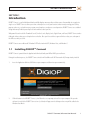
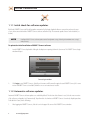
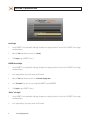
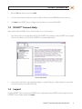
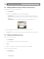
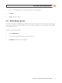
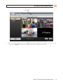
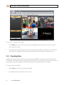
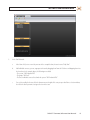
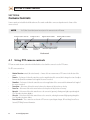
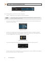
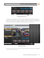
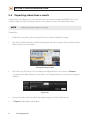
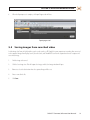
DIGIOP™ Connect
Software User Manual
Products: AH Series, EH Series, PH Series Hybrid DVRs
AI Series, EI Series NVRs
Please read this manual before using your software, and always follow the instructions
proper use. Save this manual for future reference.
DO_Connect_SM
7/18/11
LEGAL NOTICE
DIGIOP™ products are designed to meet safety and performance standards with the use of specific DIGIOP
authorized accessories. DIGIOP disclaims liability associated with the use of non-DIGIOP authorized accessories.
The recording, transmission, or broadcast of any person’s voice without their consent or a court order is strictly
prohibited by law.
DIGIOP makes no representations concerning the legality of certain product applications such as the making,
transmission, or recording of video and/or audio signals of others without their knowledge and/or consent. We
encourage you to check and comply with all applicable local, state, and federal laws and regulations before
engaging in any form of surveillance or any transmission of radio frequencies.
Other trademarks and trade names may be used in this document to refer to either the entities claiming the marks
and names or their products. DIGIOP, Inc. disclaims any proprietary interest in trademarks and trade names other
than its own.
Microsoft, Windows, and Internet Explorer are either registered trademarks or trademarks of Microsoft Corporation in
the United States and/or other countries.
No part of this document may be reproduced or distributed in any form or by any means without the express written
permission of DIGIOP, Inc.
© 2011 DIGIOP, Inc. All Rights Reserved.
3850 Priority Way South Drive, Suite 200, Indianapolis, IN 46240
Sales/Support: 1.877.972.2522
ii
www.digiop.com
Table of Contents
SECTION 1
SECTION 2
SECTION 3
SECTION 4
SECTION 5
Introduction . . . . . . . . . . . . . . . . . . . . . . . . . . . . . . . . . . . . . . . . . . . . . . . . . . . . . . . . . . . . . . . . . . . . . . . . 1
1.1 Installing DIGIOP™ Connect. . . . . . . . . . . . . . . . . . . . . . . . . . . . . . . . . . . . . . . . . . . . . . . . . . . . . . . . . . . . 1
1.1.1 Initial check for software updates . . . . . . . . . . . . . . . . . . . . . . . . . . . . . . . . . . . . . . . . . . . . . . . . . . 2
1.1.2 Automatic software updates . . . . . . . . . . . . . . . . . . . . . . . . . . . . . . . . . . . . . . . . . . . . . . . . . . . . . . 2
1.2 Login options. . . . . . . . . . . . . . . . . . . . . . . . . . . . . . . . . . . . . . . . . . . . . . . . . . . . . . . . . . . . . . . . . . . . . . . . 3
1.3 DIGIOP™ Connect Help . . . . . . . . . . . . . . . . . . . . . . . . . . . . . . . . . . . . . . . . . . . . . . . . . . . . . . . . . . . . . . . 5
1.4 Logout. . . . . . . . . . . . . . . . . . . . . . . . . . . . . . . . . . . . . . . . . . . . . . . . . . . . . . . . . . . . . . . . . . . . . . . . . . . . . 5
Configuring DIGIOP™ Connect. . . . . . . . . . . . . . . . . . . . . . . . . . . . . . . . . . . . . . . . . . . . . . . . . . . . . . . . . . 6
2.1 Initial server configuration . . . . . . . . . . . . . . . . . . . . . . . . . . . . . . . . . . . . . . . . . . . . . . . . . . . . . . . . . . . . 6
2.2 Adding additional sources (Video or Data Servers) . . . . . . . . . . . . . . . . . . . . . . . . . . . . . . . . . . . . . . . . 8
2.3 Editing and deleting sources. . . . . . . . . . . . . . . . . . . . . . . . . . . . . . . . . . . . . . . . . . . . . . . . . . . . . . . . . . . 8
2.4 Refreshing sources. . . . . . . . . . . . . . . . . . . . . . . . . . . . . . . . . . . . . . . . . . . . . . . . . . . . . . . . . . . . . . . . . . . 9
View Video or Data. . . . . . . . . . . . . . . . . . . . . . . . . . . . . . . . . . . . . . . . . . . . . . . . . . . . . . . . . . . . . . . . . . 10
3.1 Layout Options. . . . . . . . . . . . . . . . . . . . . . . . . . . . . . . . . . . . . . . . . . . . . . . . . . . . . . . . . . . . . . . . . 11
3.2 Creating Groups. . . . . . . . . . . . . . . . . . . . . . . . . . . . . . . . . . . . . . . . . . . . . . . . . . . . . . . . . . . . . . . . . . . . .12
3.3 Creating Tour. . . . . . . . . . . . . . . . . . . . . . . . . . . . . . . . . . . . . . . . . . . . . . . . . . . . . . . . . . . . . . . . . . . . . . . 14
3.3.1 Edit Tour . . . . . . . . . . . . . . . . . . . . . . . . . . . . . . . . . . . . . . . . . . . . . . . . . . . . . . . . . . . . . . . . . . . . . . 17
3.4 Viewing frame functions. . . . . . . . . . . . . . . . . . . . . . . . . . . . . . . . . . . . . . . . . . . . . . . . . . . . . . . . . . . . . 18
3.5 Undocking and re-docking viewing frames . . . . . . . . . . . . . . . . . . . . . . . . . . . . . . . . . . . . . . . . . . . . . 19
Camera Controls. . . . . . . . . . . . . . . . . . . . . . . . . . . . . . . . . . . . . . . . . . . . . . . . . . . . . . . . . . . . . . . . . . . . 20
4.1 Using PTZ camera controls. . . . . . . . . . . . . . . . . . . . . . . . . . . . . . . . . . . . . . . . . . . . . . . . . . . . . . . . . . . . 20
4.2 Using camera preset controls (PTZ cameras only) . . . . . . . . . . . . . . . . . . . . . . . . . . . . . . . . . . . . . . . . 21
4.3 Using digital zoom camera controls. . . . . . . . . . . . . . . . . . . . . . . . . . . . . . . . . . . . . . . . . . . . . . . . . . . . 21
4.4 Using audio controls. . . . . . . . . . . . . . . . . . . . . . . . . . . . . . . . . . . . . . . . . . . . . . . . . . . . . . . . . . . . . . . . . 22
Searching Recorded Video. . . . . . . . . . . . . . . . . . . . . . . . . . . . . . . . . . . . . . . . . . . . . . . . . . . . . . . . . . . . 23
5.1 Playback (transport) controls. . . . . . . . . . . . . . . . . . . . . . . . . . . . . . . . . . . . . . . . . . . . . . . . . . . . . . . . . 23
5.2 Replay search (quick video search). . . . . . . . . . . . . . . . . . . . . . . . . . . . . . . . . . . . . . . . . . . . . . . . . . . . . 23
5.3 Calendar and Thumbnails searching . . . . . . . . . . . . . . . . . . . . . . . . . . . . . . . . . . . . . . . . . . . . . . . . . . . 24
5.3.1 Calendar search method. . . . . . . . . . . . . . . . . . . . . . . . . . . . . . . . . . . . . . . . . . . . . . . . . . . . . . . . . 25
5.3.2 Thumbnails search method . . . . . . . . . . . . . . . . . . . . . . . . . . . . . . . . . . . . . . . . . . . . . . . . . . . . . . 26
5.4 Exporting video from a search . . . . . . . . . . . . . . . . . . . . . . . . . . . . . . . . . . . . . . . . . . . . . . . . . . . . . . . . 30
5.5 Saving images from searched video. . . . . . . . . . . . . . . . . . . . . . . . . . . . . . . . . . . . . . . . . . . . . . . . . . . . 31
DIGIOP™ Connect Software User Manual
iii
iv
www.digiop.com
SECTION 1: INTRODUCTION
SECTION 1
Introduction
DIGIOP™ Connect is a unified dashboard that beautifully displays numerous video and data sources from multiple sites together in
single screen. DIGIOP™ Connect allows you to have a virtual presence in all your locations and to remotely manage your facilities,
property and assets; cash and inventory; customers and employees; and processes and operations. DIGIOP™ Connect uses a tabbed
design with many flexible layouts of up to 36 video and data sources per tab.
With powerful search tools like Thumbnail Search, Timeline Search, Replay Search, Digital Zoom, and Tours, DIGIOP™ Connect makes
finding the video or data you need simpler than ever before. Once you’ve located that segment of video or data, save and export it
for offline use with just a click.
DIGIOP™ Connect runs on Microsoft® Windows® XP Professional with SP2, Windows Vista, and Windows 7.
1.1 Installing DIGIOP™ Connect
DIGIOP™ Connect is provided on the Application disk included with your NVR or hDVR system software.
During the installation process, the DIGIOP™ Connect installer will load Microsoft .NET Framework 4.0, if not previously installed.
1.
Insert the Application disk into a DVD drive on your computer and allow it to open automatically.
2.
Cllick the button to load DIGIOP™ Connect , then follow the screen prompts to install it on your computer. After you the
software is installed, the DIGIOP™ Connect icon (see below) will appear on the desktop and an entry will be added to the
Windows Start Menu.
DIGIOP™ Connect Software User Manual
1
SECTION 1: INTRODUCTION
1.1.1 Initial check for software updates
By default, DIGIOP™ Connect will check for updates automatically after login. Updated software ensures that you have the most
recent enhancements for both the DIGIOP™ Connect software and online help. The automatic update feature can be disabled (see
below).
NOTE
Installing a DIGIOP™ Connect software update retains all configuration settings (including video and data source settings)
made previously.
To update the initial installation of DIGIOP™ Connect software
1.
Launch DIGIOP™ Connect by double clicking the desktop icon or opening it from the Start menu. The DIGIOP™ Connect login
window will open.
Connect Login window
2.
Click Login to start DIGIOP™ Connect. (Initially, no Username and Password is required to start DIGIOP™ Connect.) If a newer
version of DIGIOP™ Connect is available, follow the on-screen instructions to install it.
1.1.2 Automatic software updates
Automatic DIGIOP™ Connect software updates are enabled by default. The first time this software is used, it checks newer versions
of the software, and updates itself automatically. To perform this check whenever DIGIOP™ Connect is launched, skip this procedure.
To disable this feature, do the following:
1.
2
After logging into DIGIOP™ Connect, click the icon in the upper-left corner of the DIGIOP™ Connect window.
www.digiop.com
SECTION 1: INTRODUCTION
Automatically Check for Updates option
2.
In the drop-down window, if the option Automatically Check for Updates is checked, click it to disable the option. The
checkbox will be replaced by an X-box icon.
NOTE
If the option to Automatically Check for Updates is disabled, it is highly recommended to manually check for
updates periodically. To manually check for updates, click the Check for Updates option in the drop-down list.
1.2 Login options
DIGIOP™ Connect provides three types of login options depending on how your DIGIOP™ NVR/hDVR is configured:
•
•
•
Local: This type of site login allows you to setup access to several video and data servers and to establish groups and
tours. All connection settings, including your username and password for each NVR/hDVR and the Groups and Tours you
created, are saved on the computer you logged in with. elements.digiop.com: This login option is available when DIGIOP™ provides hosted services for your NVRs and hDVRs.
Your account will have a unique Customer name assigned by DIGIOP™, and your connection settings,users, permissions, tours
and groups setup, etc are saved at DIGIOP™. This type of login allows you to automatically retrieve these settings from any
computer you log in from.
Other: You can use this type of login to connect to a single NVR or hDVR. Your access to the NVR or hDVR provides all the
privileges assigned to your username, including all Groups and Tours you can use that were configured through DIGIOP™
Control. When you use this option, you will connect to both the video and data server in you NVR or hDVR.
DIGIOP™ Connect Software User Manual
3
SECTION 1: INTRODUCTION
Local login
1.
Launch DIGIOP™ Connect by double clicking the desktop icon or opening it from the Start menu. The DIGIOP™ Connect login
window will open.
2.
Open the Site drop-down menu and select (local).
3.
Click Login to open DIGIOP™ Connect.
DIGIOP Hosted login
1.
Launch DIGIOP™ Connect by double clicking the desktop icon or opening it from the Start menu. The DIGIOP™ Connect login
window will open.
2.
In the Login window, enter your Username and Password.
3.
Open the Site drop-down menu and select elements.digiop.com.
4.
In the Customer field, enter the name assigned by DIGIOP™ to your NVR/hDVR.
5.
Click Login to open DIGIOP™ Connect.
“Other” site login
1.
Launch DIGIOP™ Connect by double clicking the desktop icon or opening it from the Start menu. The DIGIOP™ Connect login
window will open.
2.
In the Login window, enter your Username and Password.
4
www.digiop.com
SECTION 1: INTRODUCTION
3.
Open the Site drop-down menu and select other.
4.
In the Site field, overwrite the word “other” with the IP address or DNS name of the NVR/hDVR you want to connect to.
5.
Click Login to open DIGIOP™ Connect and login to the video and data servers in your NVR or hDVR.
1.3 DIGIOP™ Connect Help
Help is available within the DIGIOP™ Connect software window. To access the Help feature:
1.
Either click the Help icon in the upper right-hand side of the DIGIOP™ Connect window, or click the DIGIOP™ icon in the upper
left-hand corner and then select View Help. A DIGIOP™ Connect Help window will open.
Connect Help window
2.
Each item in the Contents tab can be expanded by clicking the + symbol. Clicking the - symbol collapses the content. Index
and Search methods are also available within Help.
1.4 Logout
To log out of DIGIOP™ Connect and return to the DIGIOP™ Connect Login window, click the DIGIOP™ icon in the upper left corner of
the DIGIOP™ Connect window, and then click Logout.
DIGIOP™ Connect Software User Manual
5
SECTION 2: CONFIGURING CONNECT
SECTION 2
Configuring DIGIOP™ Connect
When DIGIOP™ Connect is installed and launched for the first time, the Configuration tab is displayed. After the initial Video server is
configured, Video servers and data servers can be added by following the steps in the Adding Additional Sources section.
Source Management Tab View
2.1 Initial server configuration
To enter a video server or data server to DIGIOP™ Connect after the initial installation, perform the following steps:
1.
Launch DIGIOP™ Connect by double clicking the DIGIOP™ Connect icon on the desktop.
2.
Click Login.
3.
Enter the video server or data server configuration fields with the information necessary to identify your source. It may
include:
——
——
6
IP Address or Hostname – This is the IP address or the host name of the video server or data server
Username – This is the username that is to be used to access the Video server or data server.
www.digiop.com
SECTION 2: CONFIGURING CONNECT
——
——
——
——
——
4.
Password – This is the password associated with Username.
Port – (Visible for data servers only.) The TCP/IP port number that DIGIOP™ Connect will use to connect to the data
server. The default port number used by DIGIOP™ Connect is 24752.
Time zone – (Visible for Video Servers only). Select the time zone where the Video server or data server is located
from the drop-down list.
Name (optional) – This is the name that identifies the video server or data server within DIGIOP™ Connect.
Description (optional) – Enter a description of the system or other information.
Click Save. DIGIOP™ Connect will connect to the video server or data server and display the Name in the left panel Systems
list.
Example List of Systems
DIGIOP™ Connect Software User Manual
7
SECTION 2: CONFIGURING CONNECT
2.2 Adding additional sources (Video or Data Servers)
To add additional video server or data server to DIGIOP™ Connect:
1.
Click the Configuration tab.
2.
Click the down arrow on the Add icon, and then select one of the following options:
——
——
Digiop Data Server – Select this to add a data source from a database or third party software program. Data
sources may include cash register point of sale, electronic access control, time and attendance, video analytics, or
other systems.
Digiop Video Server – Select this to add a NVR or hDVR. It allows the viewing of individual cameras.
3.
Enter the configuration fields with the information necessary to identify your source. See section 2.1.
4.
Click Save. DIGIOP™ Connect will connect to the video or data server, and display the Name in the left panel Systems list.
2.3 Editing and deleting sources
To edit a source, perform the following steps:
1.
Click the Configuration tab.
2.
Select (click to highlight) the item within the Systems or Groups lists to be edited.
3.
Click Edit.
4.
Make the necessary changes to the information in the configuration fields, and then click Save.
To delete a source, perform the following steps:
1.
8
Click the Configuration tab.
www.digiop.com
SECTION 3: VIEW VIDEO OR DATA
2.
Select (i.e., click to highlight) the item to be deleted within the Systems or Groups lists.
3.
Click Delete.
4.
Click OK to confirm the deletion.
2.4 Refreshing sources
The Refresh feature updates the DIGIOP™ Connect window after changes were made to the video or data sources. For instance, if a
camera name in a video server to which DIGIOP™ Connect is connected was changed, the new name will appear after the DIGIOP™
Connect window is refreshed.
To perform a refresh, do the following:
1.
Click the Configuration tab.
2.
Select the source to be updated within the Systems or Groups lists.
3.
Click Refresh to update the system configuration.
DIGIOP™ Connect Software User Manual
9
SECTION 3: VIEW VIDEO OR DATA
SECTION 3
View Video or Data
With DIGIOP™ Connect you can view:
•
•
DIGIOP™ Video Server: This represents a DVR and will allow the viewing of individual cameras.
DIGIOP™ Data Server: Use this option to add a data source from a database or third party software. (Data sources may
include cash register point of sale, electronic access control, time and attendance, video analytics, or other systems.)
DIGIOP™ Connect supports layouts with up to 36 frames. To view a video or data source:
1.
Click the triangle to the left of a System name to expand its list. For Video Servers, the camera list is displayed. For Data
Servers, data channels are displayed.
2.
Click the Home tab, and then click the Live icon (or open the dropdown list under the Layout icon to select the layout of
camera images to be shown).
3.
Click and hold down the mouse button on an item listed in the Systems list and drag it to a viewing frame. The video or data
stream from that item will appear. Repeat with other items listed in the Systems or Groups lists that you want to see.
10
www.digiop.com
SECTION 3: VIEW VIDEO OR DATA
Example showing three cameras on a Live tab
NOTE
Dragging the name of a video server listed in the Systems or Groups lists to any viewing frame displays video from all
cameras monitored by that Video server.
3.1 Layout Options
You can create camera and/or data layouts that fit the specific needs of your surveillance or business intelligence objectives. Multiple
tabs can be setup, with 2 x 2 frame grids to layouts for up to 36 cameras.
To select a layout, click the Home tab, click the down arrow on the Layout icon, then click the layout pattern you prefer to use.
DIGIOP™ Connect Software User Manual
11
SECTION 3: VIEW VIDEO OR DATA
3.2 Creating Groups
Camera images in DIGIOP™ Connect can be saved as a group. The name given to a group is displayed in the Groups list. Like a
system, a group can be displayed at any time.
To save displayed camera images as a group name, do the following:
1.
Open a selection of camera images or data sources in the viewing frames.
2.
Click the Home tab, and then click the Save Group icon.
12
www.digiop.com
SECTION 3: VIEW VIDEO OR DATA
Save Group
3.
Enter a name in the Group Name field, then click Save. The group name will appear in the Groups list. To see the cameras in
the list, click the Groups title bar, then click the triangle to the left of the group name you created.
DIGIOP™ Connect Software User Manual
13
SECTION 3: VIEW VIDEO OR DATA
To view the items in a group, do the following:
1.
Click the Home tab, and then click the Live icon (or open the dropdown list under the Layout icon to select the layout of
camera images to be shown).
2.
Click and hold down the mouse button on an item listed in the Groups list and drag it to a viewing frame. The video or data
stream from that item will appear. Repeat with other items listed in the Systems or Groups lists that you want to see.
3.3 Creating Tour
Individual camera images, Groups, and Systems can viewed sequentially in DIGIOP™ Connect by constructing a Tour. In the Tour,
each individual camera, Group, or System is assigned a dwell time and a position in the order of items that are included. The tour can
be played, paused, manually stepped back to the previous image(s) shown or stepped forward to the next images.
To construct a tour, do the following:
1.
Click the Tours bar in the left frame (below the Groups bar).
2.
In the blank space below the Tours bar to “add a new tour.”
14
www.digiop.com
SECTION 3: VIEW VIDEO OR DATA
3.
In the Tour Editor tab:
a.
In the Name field, enter a name for your tour. In the example below, the tour is named “Indy Tour”.
b.
Add individual cameras, systems, or groups to the tour by dragging them from the left frame and dropping them into
the Items box. In the example above, the following were added:
- The system: “2011 Industrial Rd.”
- The group: “2011 Ind.”
- The three individual cameras listed under the system “2011 Industrial Rd.”
c.
For each item added to the tour, click the down arrow on the right of the entry to open dwell time selection window,
then click the dwell you want to assign to the item in the tour.
DIGIOP™ Connect Software User Manual
15
SECTION 3: VIEW VIDEO OR DATA
d.
4.
16
Click Save to save your tour.
To run the tour, drag the tour name (“Indy Tour” here) to an unassigned pane in the viewing frame. Click the tour play control
buttons in the upper-left corner to “Step Back”, “Pause”, resume “Play”, and “Step Forward”.
www.digiop.com
SECTION 3: VIEW VIDEO OR DATA
Tour Play Control Buttons
3.3.1 Edit Tour
To edit a tour:
1.
Close the tour if it is running.
2.
Click the Configuration tab at the top of the window.
3.
In the Tours list, click the tour entry you want to edit.
4.
Click the Edit icon the Configuration tab.
DIGIOP™ Connect Software User Manual
17
SECTION 3: VIEW VIDEO OR DATA
5.
In the Tour Editor tab, click the item entry you want to change to highlight it.
——
——
——
6.
To change the dwell time, click the down arrow on the right of the item bar, then select the new dwell time for that
item.
To change the order of the items in the display, click the item to highlight it, then click the up and/or down buttons to
the right of the Items list to reposition it in the list order.
To delete an item, click the item to highlight it, then click the “X” button to the right of the Items list.
Click Save to save the changes you made to the tour.
3.4 Viewing frame functions
Video from individual cameras can be:
•
•
•
•
double-clicked within the viewing frame to toggle to and from a single-pane view
selected (highlighted) in the Systems or Groups lists and viewed as live video
play back (simultaneously affects all displayed video panes) 1, 2, 5, or 15 minutes of recorded video
searched
Viewing frames can be selected (i.e., highlighted) by mouse click and:
•
•
•
•
18
displayed as Full Screen (type the ESC key to revert back)
viewed in a variety of viewing layouts (up to 36 camera images on a single tab)
closed (which will remove the camera images as well as the viewing tab)
cleared
www.digiop.com
SECTION 3: VIEW VIDEO OR DATA
3.5 Undocking and re-docking viewing tabs
Any selected tab can be undocked from the DIGIOP™ Connect software panel. This feature allows the undocked tab to be moved
freely on the desktop while simultaneously viewing other tabs still attached to the software panel. See below. The undocked tab
can be re-attached (docked) with a single mouse click.
To release a viewing pane tab so that it is unattached from the DIGIOP™ Connect software panel, perform the following steps:
This feature allows for full multi-monitor support. This feature can be setup so that one tab can be showing live video from a
camera, while another tab can be used for searching recorded video.
1.
Make sure the viewing tab to be released from the software window is active in the viewing area.
NOTE
2.
The undock feature affects all of the frames being displayed in the tab.
Either click the Undock tab icon, or click and hold the tab and drag it from the software window.
Drag the viewing tab out of the
window to make a separate window
3.
To re-attach the viewing tab to the DIGIOP™ Connect software window, click the Dock tab icon.
DIGIOP™ Connect Software User Manual
19
SECTION 4: CAMERA CONTROLS
SECTION 4
Camera Controls
Camera controls are included in the Media tab menu. The controls enabled for a camera are dependent on the features of the
camera selected.
NOTE
The PTZ (Pan, Tilt, and Zoom) controls are only active if the camera selected is a PTZ camera.
PTZ direction controls
Iris Open/close
Focus
Near/Far
PTZ Preset
controls
Zoom
In/Out
Digital Zoom In/Out
Volume Mute Control
Maintain Aspect Ratio
Media controls
4.1 Using PTZ camera controls
PTZ camera controls become active when the Media tab is selected and the camera selected is a PTZ camera.
The PTZ camera controls are:
•
•
•
•
•
•
•
•
20
Motion Direction controls (directional arrows) – A mouse click on an arrow moves a PTZ camera in the direction of the
arrow.
Zoom In – Each mouse click on this control increases the magnification of the camera (which enlarges the view of an object
for more detail) until the maximum focal length of the camera is reached.
Zoom Out – Each mouse click on this control decreases the magnification of the camera until the minimum focal length of
the camera is reached.
Focus Near – Each mouse click on this control enhances the sharpness of objects that are close by.
Focus Far – Each mouse click on this control enhances the sharpness of objects that are far away.
Open Iris – Each mouse click on this control increases the camera iris (aperture), allowing more light to pass through the
lens. This makes the picture brighter.
Close Iris – Each mouse click on this control decreases the camera iris, reducing the amount of light passing through the
lens. This makes the picture darker.
Preset Controls – These controls are used to aim a PTZ camera at a predesignated target. Refer to Using Camera Preset
Controls (PTZ Only) for more information.
www.digiop.com
SECTION 4: CAMERA CONTROLS
4.2 Using camera preset controls (PTZ cameras only)
The Preset Controls allow you to setup a PTZ camera to quickly move to preset target. Each target position is assigned a number.
When the camera is selected and the number is “Called”, it quickly moves to that target.
•
•
Set – Click to assign a number (1 to 32) to the position currently being used by the camera.
Call – Click to move the camera to the pre-designated direction.
To assign a preset number to a camera direction:
1.
Use the PTZ direction controls to aim the camera at a target.
2.
Click the number (1 to 32) to assign to the camera direction.
3.
Click Set to assign the set direction to the number.
4.
Repeat Steps 1-3 above for each additional camera.
To Call the camera to a preset direction:
1.
Select the camera viewing frame.
1.
Click the number (1 to 32) assigned to the camera direction you want see. The number will appear in the blank box.
2.
Click Call.
4.3 Using digital zoom camera controls
The controls listed below will work with all digital video cameras (including PTZ cameras). The controls become active for the
camera selected in the viewing pane (refer to “View Video or Data”) and the “Video” tab is the tab in use. The digital zoom video
camera controls are:
•
•
Maintain Aspect ratio – Click this control to toggle between the original width and height of the video (whatever the
camera is set to), and the width and height of the viewing pane. The video will assume the size (ratio of the width and
height) of the viewing pane.
Zoom In/Out – To use this feature, select the camera pane, click the Enable Digital Zoom icon in the Media menu (see
above), then use the “+” and “-” keys on the keyboard or the mouse wheel to zoom in and out.
DIGIOP™ Connect Software User Manual
21
SECTION 4: CAMERA CONTROLS
4.4 Using audio controls
Audio controls are enabled for camera channels with sound enabled Audio controls become active when the Media tab is selected
and the camera selected has a audio features.
Audio controls
The camera audio controls are:
•
•
22
Mute – Clicking this control mutes the sound from the camera selected.
Un-mute Selected Audio – Clicking this control enables the sound from the selected camera to be heard. The volume
controls of the computer and of the DIGIOP™ Connect software can used to increase or decrease the volume level.
www.digiop.com
SECTION 5: SEARCHING RECORDED VIDEO
SECTION 5
Searching Recorded Video
Connect provides different methods for finding recorded video. These methods include:
•
•
•
Replay Search (Quick Video Search)
Calendar Search
Thumbnails Search
Use Replay Search find recorded live video for events that occurred within the previous 15 minutes. For older events, the Calendar
and Thumbnail searching features provide a precise way to find recorded video. Regardless of the type of search used, a user can
switch from recorded video to live video by clicking a viewing tab. Also, live video and recorded video can be viewed concurrently
through use of the Undock feature.
NOTE
Multiple recordings can be searched simultaneously by using the Layout icon and selecting a view where several camera
images are displayed within a viewing tab.
NOTE
During a Search, camera(s) selected in the Systems or Groups lists are displayed above the Timeline. All cameras displaying
images are selected during a search.
5.1 Playback (transport) controls
Video playback controls are displayed whenever the Replay or the Search icon is clicked, or when the Replay or Search viewing tabs
are active. The playback controls for video searching include:
•
•
•
•
Pause – Pauses the video being played.
Play – Starts playing the video from the point where the scrub bar is located on the Timeline.
Step Forward – Advances the search playback one frame at a time.
Fast Forward – Increments the speed of video play each time it is clicked. Increments are 2x, 4x, 8x, 16x, 32x, 64x, and
128x.
5.2 Replay search (quick video search)
Replay search allows a user to search for and replay video in the previous 15 minutes. To use Replay search, do the following:
1.
Select the Live viewing tab with the cameras you want to use for the Replay search.
NOTE
It does not matter if a camera frame is selected (highlighted). Replay affects all of the camera images being displayed.
DIGIOP™ Connect Software User Manual
23
SECTION 5: SEARCHING RECORDED VIDEO
2.
With the Home tab selected, click the down arrow on the Replay icon to replay 1, 2, 5, or 15 minutes of recorded video.
3.
Use the recorded video transport controls to pause, play, step forward or fast forward playback.
5.3 Calendar and Thumbnails searching
The Calendar and the Thumbnails searching methods allow a user to search recorded video in increments that can be set as seconds,
minutes, hours, days, or months.
To implement one of these search methods, do the following:
1.
Select the camera that you want to search from the Systems or Groups list.
2.
Click the Home tab, and then click the Search icon. A window similar to that shown below will be displayed.
24
www.digiop.com
SECTION 5: SEARCHING RECORDED VIDEO
Searching video
3.
Click either the Calendar or Thumbnails tab. These tabs are located beneath the timeline.
4.
Use the video transport controls review the video segments.
For details on using either search method, refer to the Calendar search method and Thumbnails search method sections
below.
NOTE
Use the Calendar view first to establish the time range of video to be searched. The Thumbnails view is another way to view
the video once the time range is determined. The Timeline is used to mark the time frame of the event until the exact time
and video of the event or detail is found.
5.3.1 Calendar search method
Calendar video search allows you to search video by date, time, and duration with the use of a timeline.
DIGIOP™ Connect Software User Manual
25
SECTION 5: SEARCHING RECORDED VIDEO
Duration Length
Start Field
Increment
Calendar Icon
Collapse or Expand Timeline
Timeline Zoom In/Out
History
Calendar search method
Use the following guidelines to configure the time range of the search:
•
•
•
•
In the Start field, click the date entry or click the calendar icon to open a calendar window. Click the start date in the calendar,
and then click the calendar icon again to close the calendar window.
Clicking and holding the mouse pointer on the characters in the month, day, year, hour, minute, or second fields produces a
selector cursor. Sliding the cursor upwards or downwards increments or decrements the value in that field.
Use the Duration drop down list, select a time increment: seconds, minutes, hours, days, or months.
Edit a duration number (length) in the Duration field.
After the time range is established, the timeline can be used to refine the search. The Start field can be collapsed (hidden) or
expanded (shown) by clicking icon in the lower right corner.
5.3.2 Thumbnails search method
Thumbnails search method presents 10 thumbnails of video frames, spaced across a defined time range, to help locate a detail or
event of interest.
Thumbnails search method
26
www.digiop.com
SECTION 5: SEARCHING RECORDED VIDEO
Use the following guidelines to perform a Thumbnails search:
•
•
•
Clicking the forward or backward arrow at either end of the thumbnails shifts the thumbnails left (forward in time) or
right (back in time) within the time range of the video frames being searched. This also affects the timeline, increasing or
decreasing the range of time shown.
Clicking on a thumbnail also affects the time grid scrub bar, increasing or decreasing the range of time shown above the
thumbnails.
Resting the cursor on a thumbnail expands the image.
Highlighted thumbnail range
NOTE
•
A slider bar, for adjusting the timeline view forward or backward, may be visible directly under the thumbnails depending on
the time range of the video selected.
Placing the cursor on a thumbnail and holding the cursor there for about one second will enlarge the view of that thumbnail.
The time and date of the video frame is also displayed in the enlarged view. If the cursor is not moved from the thumbnail,
the enlarged view stays open for 15 seconds.
TIMELINE USAGE (CALENDAR AND THUMBNAILS)
The Timeline tool is a graphical representation of a defined time range of recorded video frames. Since recorded video frames
are equal to a set amount of time, observing video within a timeline helps a user determine the exact time that an event or detail
occurred.
DIGIOP™ Connect Software User Manual
27
SECTION 5: SEARCHING RECORDED VIDEO
Timeline Tool
Use the following guidelines to use the Timeline tool for searching video:
•
Scrub Bar – Scrub Bar allows a user to navigate across a range of recorded video.
NOTE
•
If multiple recordings (cameras, viewing panes) are simultaneously being searched, all of the viewing panes will show the
result of the scrub when the scrub bar is released.
Use the mouse cursor to drag the scrub bar back and forth along the timeline to move forward or backward within the time
range of the video being searched.
Dragging the scrub bar
•
•
Increasing or decreasing the range of the timeline determines how many frames of video are used within the time grid.
The time range can lengthened or decreased by dragging the handles at each end of the timeline. When using this feature,
the handle is highlighted and the cursor changes to an increase/decrease cursor.
Time range increase/decrease
•
Use the mouse to drag the timeline back and forth to adjust the start and end times of the video being searched.
Dragging the Time Grid
•
28
The Timeline Zoom In or Timeline Zoom Out buttons are used to expand (stretch) or contracts (shrink) the timeline displayed.
One click on either button changes the compression by 50%.
www.digiop.com
SECTION 5: SEARCHING RECORDED VIDEO
Timeline Zoom In/Out
Narrowing the Search to an Event
•
A record of each action taken during a search is recorded in a Timeline History. Each record includes the time the action was
taken and the time range of the video searched. This feature allows you to quickly return to a point of interest during a search
by clicking on the record. Click the History toggle button to display the record list; click it again to close it. Clicking the arrows
on either side of the toggle button moves forwards or backwards within the time ranges in the history.
Example Timeline History
•
The Timeline History is saved until the Search (tab) is closed, or until the top or bottom end-point of the history is highlighted
and another action is taken on the timeline.
DIGIOP™ Connect Software User Manual
29
SECTION 5: SEARCHING RECORDED VIDEO
5.4 Exporting video from a search
A range of video selected during a search can be exported to a drive connected to the computer using DIGIOP™ Connect. This is
useful, for example, if the video needs to be given to police or other authorities. A viewer can be exported with the video.
NOTE
A Replay Search (quick video search) can not be exported.
To Export video:
1.
Establish the time range of the video to be exported. Refer to the Calendar and Thumbnails Searching.
2.
Click either the top half of the Export icon (default for exporting the entire timeline range), or click on the bottom half of the
Export icon and select one of the options.
Selecting video range for export
3.
After the time range of the video is selected, an Export menu is displayed below the camera frames. Click Browse to
select the destination (Export Path) where the video will be sent. The Export button becomes active when the export path
established.
Export menu
4.
If you want to include a video viewer with the video clip being exported, check the Include Viewer box.
5.
Click Export. An Export Progress tab will appear.
30
www.digiop.com
SECTION 5: SEARCHING RECORDED VIDEO
6.
When the Export process is complete, the Export Progress tab will close.
Export progress tab
5.5 Saving images from searched video
A video image (one frame of video) within a search can be saved as a JPG (.jpg) file to your computer or to another drive connected
to the computer. Images from Replay Search, Calendar Search, and Thumbnails Search can be captured and saved. To capture and
save a video image:
1.
Find the image to be saved.
2.
Click the Save Image icon. This will capture the image, and the Save Image window will open.
3.
Browse to select the destination where the captured image will be sent.
4.
Enter a name for the file.
5.
Click Save.
DIGIOP™ Connect Software User Manual
31