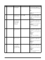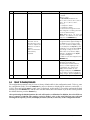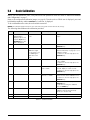
1
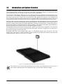
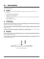
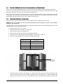
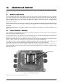
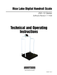
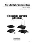
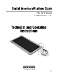
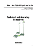
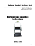
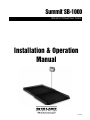
Summit SB-1000
®
Bariatric Wheelchair Scale
Installation & Operation
Manual
106992
Contents
1.0
Introduction and System Overview.............................................................................................. 1
2.0
Scale Installation......................................................................................................................... 2
2.1
2.2
2.3
2.4
2.5
2.6
3.0
Overview . . . . . . . . . . . . . . . . . . . . . . . . . . . . . . . . . . . . . . . . . . . . . . . . . . . . . . . . . . . . . . . . . . . . . .
Site Preparation . . . . . . . . . . . . . . . . . . . . . . . . . . . . . . . . . . . . . . . . . . . . . . . . . . . . . . . . . . . . . . . . .
Unpacking . . . . . . . . . . . . . . . . . . . . . . . . . . . . . . . . . . . . . . . . . . . . . . . . . . . . . . . . . . . . . . . . . . . . .
Bariatric Wheelchair Scale Feet Assembly and Adjustment . . . . . . . . . . . . . . . . . . . . . . . . . . . . . . . . .
Electrical Interface to Indicator . . . . . . . . . . . . . . . . . . . . . . . . . . . . . . . . . . . . . . . . . . . . . . . . . . . . . .
Access Ramps . . . . . . . . . . . . . . . . . . . . . . . . . . . . . . . . . . . . . . . . . . . . . . . . . . . . . . . . . . . . . . . . . .
2
2
2
3
3
4
Adjustments and Calibration ....................................................................................................... 5
3.1 Mechanical Adjustments. . . . . . . . . . . . . . . . . . . . . . . . . . . . . . . . . . . . . . . . . . . . . . . . . . . . . . . . . . . 5
3.2 Corner Correction. . . . . . . . . . . . . . . . . . . . . . . . . . . . . . . . . . . . . . . . . . . . . . . . . . . . . . . . . . . . . . . . 5
3.3 Calibration Procedure. . . . . . . . . . . . . . . . . . . . . . . . . . . . . . . . . . . . . . . . . . . . . . . . . . . . . . . . . . . . . 6
4.0
Indicator Installation and Configuration ..................................................................................... 7
4.1 Indicator Installation . . . . . . . . . . . . . . . . . . . . . . . . . . . . . . . . . . . . . . . . . . . . . . . . . . . . . . . . . . . . . . 7
4.2 Indicator Configuration . . . . . . . . . . . . . . . . . . . . . . . . . . . . . . . . . . . . . . . . . . . . . . . . . . . . . . . . . . . . 8
4.2.1
4.2.2
5.0
6.0
Indicator Calibration.................................................................................................................. 13
Scale Operation ......................................................................................................................... 14
6.0.1
6.0.2
6.0.3
7.0
Numeric Data Entry . . . . . . . . . . . . . . . . . . . . . . . . . . . . . . . . . . . . . . . . . . . . . . . . . . . . . . . . . . . . . . . . 8
Programming Mode . . . . . . . . . . . . . . . . . . . . . . . . . . . . . . . . . . . . . . . . . . . . . . . . . . . . . . . . . . . . . . . 8
Weighing . . . . . . . . . . . . . . . . . . . . . . . . . . . . . . . . . . . . . . . . . . . . . . . . . . . . . . . . . . . . . . . . . . . . . . . 14
Using the Body Mass Index (BMI) Function . . . . . . . . . . . . . . . . . . . . . . . . . . . . . . . . . . . . . . . . . . . . . 14
Using the Tare Function . . . . . . . . . . . . . . . . . . . . . . . . . . . . . . . . . . . . . . . . . . . . . . . . . . . . . . . . . . . 15
RS-232 Communications ........................................................................................................... 16
7.1 Sample and Explanation of ESC Protocol . . . . . . . . . . . . . . . . . . . . . . . . . . . . . . . . . . . . . . . . . . . . . 19
8.0
Service Information ................................................................................................................... 21
8.1 Troubleshooting Guide . . . . . . . . . . . . . . . . . . . . . . . . . . . . . . . . . . . . . . . . . . . . . . . . . . . . . . . . . . . 21
8.2 Periodic Maintenance . . . . . . . . . . . . . . . . . . . . . . . . . . . . . . . . . . . . . . . . . . . . . . . . . . . . . . . . . . . . 21
8.3 Load Cell Replacement . . . . . . . . . . . . . . . . . . . . . . . . . . . . . . . . . . . . . . . . . . . . . . . . . . . . . . . . . . 22
8.3.1
9.0
Load Cell Wiring to Junction Box. . . . . . . . . . . . . . . . . . . . . . . . . . . . . . . . . . . . . . . . . . . . . . . . . . . . . 23
Bariatric Wheelchair Scale Specifications .............................................................................. 24
9.1 Indicator Specifications. . . . . . . . . . . . . . . . . . . . . . . . . . . . . . . . . . . . . . . . . . . . . . . . . . . . . . . . . . . 24
Summit SB-1000 Limited Warranty ....................................................................................................... 25
Technical training seminars are available through Rice Lake Weighing Systems.
Course descriptions and dates can be viewed at www.ricelake.com or obtained
by calling 715-234-9171 and asking for the training department
© 2009 Rice Lake Weighing Systems. All rights reserved. Printed in the United States of America.
Specifications subject to change without notice. October 2009
i
ii
Summit SB-1000 Bariatric Wheelchair Scale Installation Manual
1.0
Introduction and System Overview
The Summit® SB-1000 Bariatric Wheelchair Scale is a heavy-duty scale that easily accommodates wheelchairs
with its large platform size and easy-access ramp. It provides exceptional performance in applications where
typical wheelchair scales are not large enough to meet the needs of the patient.
The Summit SB-1000 Bariatric Wheelchair Scale is a fully electronic, low profile floor scale that measures 36 in
x 36 in (.91 m x .91 m), and has a capacity up to 1000 lbs (500 kg). The SB-1000 uses four corner-mounted, alloy
steel shear beam load cells, with the cells recessed into the frame channels for protection. Also included is an
access ramp and signal-trim summing board enclosed in a durable ABS enclosure that has convenient side access
for any necessary corner corrections. It also comes pre-trimmed so corner corrections should not be necessary.
Load cell cables are run through the main channels, and held down with replaceable cable ties near each corner,
eliminating the possibility of cable damage in portable applications. One threaded hole, located in the center of
the deck, is another useful feature for portable applications. This allows for placement of a removable eyebolt to
lift the scale from above with chains. Because of the possibility of foot and load cell damage from forklift tines,
the scale should always be lifted from above with chains through the eyebolt.
The adjustable feet are used to allow leveling the scale to make up for minor floor irregularities. Two of the four
feet sit inside the foot keeper plates located on the front of the ramp. The ramp is designed to sit on either side of
the scale that is adjacent to the junction box.
The Summit SB-1000 comes equipped with a large 1" LCD indicator display and a 120 VAC or 230 VAC
adaptor to use when power is readily available. It is also capable of operating on the internal sealed lead-acid
rechargeable battery when no power source is available.
Figure 1-1. The Summit SB-1000 Bariatric Wheelchair Scale
This manual can be viewed and downloaded from the Rice Lake Weighing Systems web site at
www.ricelake.com/health. Rice Lake Weighing Systems is an ISO 9001 registered company.
Introduction and System Overview
1
2.0
Scale Installation
The following sections describe the correct installation procedures when installing the Summit SB-1000
Bariatric Wheelchair Scale.
2.1
Overview
Standard installation of the Summit SB-1000 Bariatric Wheelchair Scale consists of the following steps:
1. Select a site
2. Check levelness and smoothness of site
3. Unpack the scale, ramp and indicator
4. Adjust the four feet on the scale
5. Set the ramp next to the scale so that two of the scale feet set in the ramp foot keeper plates. Refer to
Section 2.6 on page 4.
6. Connect cable to the indicator
7. Calibrate the unit
2.2
Site Preparation
The scale must not be loaded beyond its capacity, even momentarily. Avoid areas where the scale might receive
damaging side impacts from wheels, or shock damage from falling objects. Avoid areas where water may
damage a scale not meant for a washdown environment.
The interface cable between the scale and the indicator must be protected against crushing, cutting, or moisture
damage. If the chosen site has such potential dangers, some method of protection, such as running the cable in
conduit, is necessary.
In operation, the scale must be level within 1/4". Either choose a site where the floor is close to this standard to
avoid excessive shimming, or modify the floor at the chosen site to meet this standard.
2.3
Unpacking
Remove all packing material and visually inspect the scale for visible damage caused during shipment. The
shipping container should contain the bariatric wheelchair scale, scale feet, a ramp, this manual, the indicator,
and a 10-ft length of load cell cable.
The Summit SB-1000 Bariatric Wheelchair Scale has one threaded eyebolt hole located in the center of the deck
to allow installation of an eyebolt hook for use when lifting the scale with chains. It’s recommended to use a 1/2
in-20NF eyebolt to lift the scale.
Figure 2-1. Proper Lifting Technique
2
Summit SB-1000 Bariatric Wheelchair Scale Installation Manual
2.4
Bariatric Wheelchair Scale Feet Assembly and Adjustment
The scale feet are shipped attached to the scale. If the feet have to be adjusted, use the following instructions.
Screw one foot into each load cell and turn all the way in until the foot touches either the load cell or the
underside of the deck. Then unscrew each foot three complete turns.
Place a spirit level on the deck. Adjust any “high” corners not in contact with the floor by further unscrewing the
feet on those corners until they just contact the floor surface. When all feet are in contact with the floor, check the
deck with the spirit level to be sure the scale is within 1/4 inch of level.
2.5
Electrical Interface to Indicator
Ten feet of 4-wire cable to connect the scale to the weight indicator is supplied with each scale.
NOTE:The cable is pre-installed from the factory but should replacement be required in the future, cable installation
instructions are shown below.
The junction box is easily accessible through an access plate located on the side of the Summit SB-1000. Use the
following steps to wire up the junction box.
1. Remove the two #10 x 3/8" screws.
2. Slide the junction box assembly out of the deck.
3. Open and remove the top of junction box.
4. Push the cable end into the junction box through a cord grip.
5. Connect the wires to the indicator terminal (Figure 2-2) as shown in Table 2-1.
6. Pull out excess and tighten the cord grip to hold the cable snugly.
Cable Color Code
Junction Box
Red
+ Excitation
Black
- Excitation
Green
+ Signal
White
- Signal
Bare
Shield
Table 2-1. Junction Box Connections
Indicator
Te r m i n a l
Location
Figure 2-2. Junction Box Wiring Diagram
7. The cable must be routed to the indicator in a manner that will protect the cable from damage. This
method of cable protection in non-washdown applications are shown in Figure 2-3. When planning cable
routing, leave a loose coil of excess cable under the scale to facilitate future lifting of the scale for
Scale Installation
3
servicing or cleaning.
SCALE FLOOR
LOAD CELL CABLE
Figure 2-3. Load Cell Protection
8. When the interface cable is protected and in its final position, complete connections to the indicator. If
necessary, trim corners as described inSection 3.2 on page 5.
9. Check all strain relief fittings for tightness.
10. Put the cover back onto the junction box assembly and slide the junction box back into the floor scale
cutout.
11. Secure the Summit SB-1000 side plate.
2.6
Access Ramps
Access ramps for Summit SB-1000 Bariatric Wheelchair Scales are designed to bolt to the floor, with built-in
mounting plates that attach to the scale feet. When used with access ramps, side movement of the scale is
automatically eliminated, and no other mounting plates are necessary.
The access ramp can only be attached to the scale on one side of the scale which is opposite the junction box. For
example, the scale shown in Figure 2-4 could have an access ramp on the left side as shown which sits opposite
the junction box. The top and bottom sides, however, will not accept the ramp mounting plates.
Junction box
location
Longitudinal axis
of load cells
Figure 2-4. Access Ramp
4
Summit SB-1000 Bariatric Wheelchair Scale Installation Manual
3.0
Adjustments and Calibration
The following sections describe adjustments that need to be made to the Summit SB-1000 Bariatric Wheelchair
Scale.
3.1
Mechanical Adjustments
To accommodate minor floor unevenness, the scale feet can be used to adjust scale height up or down a fraction
of an inch. Adjust the feet by hand (lift the scale corner slightly with a pry bar) until all feet are contacting the
floor equally. No jam nuts are supplied for locking the feet, as there is a slight decrease in accuracy when jam
nuts are tightened. However, if you feel that your application requires you to secure the feet, we suggest using
Teflon® tape or Loctite®.
When adjusting scale feet, use care to prevent the scale foot from bottoming out against the underside of the load
cell. Also, the foot stem can be damaged by bending or stripping threads if extended beyond the maximum height
adjustment.
When height adjustments are complete, recheck level of the deck with a spirit level. The deck must be level
within 1/4".
3.2
Corner Correction & Trimming
The assembled Summit SB-1000 scale is delivered with the junction box corner-trimmed. Corner trimming is
only necessary after replacing a load cell.
To calibrate the scale, the output from each load cell must be matched by adjusting the signals with
potentiometers at the junction box—a process known as trimming.
Remove the junction box cover and identify the correct load cell terminal corresponding to each corner (labeled
CELL 1, CELL 2, and so on). See Figure 8-5 on page 26 for scale deck corner numbering.
The indicator must be connected and calibrated approximately, but it need not indicate the exact weight value. A
test weight is required. The recommended test weight for the SB-1000 is 25% of scale capacity.
With no weight on the scale, zero the indicator. Then turn all four potentiometers (Figure 3-1) clockwise to
increase the reading until a clicking sound is heard from each potentiometer. This ensures the maximum signal
from each load cell.
Potentiometers
Figure 3-1. Summing Board Diagram
Teflon® and Loctite® are both registered trademarks of E.I. DuPont.
Adjustments and Calibration
5
With all potentiometers at full signal, place the test weight over one corner and record the indicated weight.
Repeat the process for each of the other three corners. The load cell with the lowest corner reading is used as a
reference point and will not be trimmed.
Next, place the test weight over one of the other three corners and use that cell’s potentiometer to adjust the cell
output down to the reference cell output. Repeat this procedure with the other two high corners.
Adjustments are somewhat interactive, and adjusting the three higher outputs may affect the reference cell
output, especially in smaller scale decks. Rezero the indicator and repeat the test until all corners read within
±.1% of the test weight used.
3.3
Calibration Procedure
Refer to the indicator section (Section 5.0) to determine correct calibration procedures.
It is recommended that the scale be “exercised” before calibration to be certain that everything is seated. Load
the scale to near capacity two or three times.
Then, with no load on the scale, place the indicator in its calibration mode and perform a zero calibration. Now
place test weights on the platform equal to 70% - 80% of the scale’s capacity. If several weights are used, they
should be evenly distributed around the platform. Perform a span calibration.
Remove the test weights and check the zero reading. Repeat the calibration process if necessary.
6
Summit SB-1000 Bariatric Wheelchair Scale Installation Manual
4.0
4.1
Indicator Installation and Configuration
Indicator Installation
The Summit SB-1000 Bariatric Wheelchair Scale has several connections on the back of the indicator.
Connection points include:
• AC power connection
• RS-232 port connection
• Scale connection port
• Adaptor storage connection
AC Power Connection
The Summit SB-1000 Scale has a 120 VAC adaptor or 230 VAC adaptor to use when power is readily available.
The AC power adaptor plugs into the back of the indicator as shown in Figure 4-1. The AC adaptor, when not in
use, plugs into the back housing of the indicator. Figure 4-1 illustrates that location.
Connect AC power
source here
LED indicator light
illuminates from red to
green when charged
S t o r e t h e 1 2 0 VA C
adaptor here when not
in use
RS-232 port connection
Store the 230 VAC adaptor
here when not in use
Removable screws
Figure 4-1. AC Power and RS-232 Connection Site with Back Plastic Cover in Place
The Summit SB-1000 Scale is capable of running its internal sealed lead-acid rechargeable battery if no
additional power source is available. Battery life is approximately 75 hours. If the LO Bat indicator is showing on
the display, recharge the battery or connect the scale to an AC power source as soon as possible for accurate
weighing.
Battery Charging
When the AC adaptor is connected to a power source, the rechargeable battery goes into recharge mode. The
LED indicator light on the back of the scale housing will illuminate red during the charging period, and change
over to green when the battery becomes fully charged.
Indicator Installation and Configuration
7
Load Cell Connections
To gain access to the load cell connection point, remove the four back retaining screws as shown in the left hand
side of Figure 4-3. Figure 4-2 illustrates where the load cell connection point is.
Scale connection (shown in
Figure 4-2 with the plastic
cover removed)
Figure 4-2. Load Cell Connection Point
4.2
Scale Configuration
Options and parameter setup are done through the scale configuration section and is used for setting values and
various parameters and options that are essential for the functioning of the system. Entry into this mode is
possible only when the scale is turned off.
4.3
Enabling Configuration or Calibration Modes
Before the scale will enter either the Configuration or Calibration mode, the configuration enable jumper must be
removed.
Access to that jumper is gained by removing the back cover of the indicator. Remove the four back cover
retaining screws as shown on the left side of Figure 4-3. With the cover removed, the jumper can be seen sticking
through the hole in the rear housing (shown in Figure 4-3 - right side). Remove that jumper to gain access to the
configuration and calibration modes.
Remove retaining screws x 4 (only 2 showing)
Remove jumper to gain access to configuration
and calibration modes
Figure 4-3. Gain Access to the Configuration/Calibration Enable Jumper on the Back of the Indicator
After configuration or calibration is done, the jumper must be replaced for normal scale operation.
NOTE: A display of Con En indicates that the jumper is not in place. Put jumper on both pins to return the scale to
normal weigh mode.
8
Summit SB-1000 Bariatric Wheelchair Scale Installation Manual
4.3.1
Configuration Mode
To get into the configuration mode, turn the scale off and remove the configuration jumper as shown in
Figure 4-3. Turn the scale on. While Start is displayed, press and hold the Kg-Lb key until IDENT appears on the
display.
To change from one parameter to the next, press the REWEIGH key once.
To change the value of the parameter, use the Kg-Lb key.
From the SAVE phase: to save the configuration data, press the REWEIGH key. DONE appears for one or two
seconds followed by Start and the display enter into weighing mode and is ready to start the weighing process. To
exit with saving changes, press the Lb/Kg key.
Varous parameters can be set up while in configuration mode
Power Off
Power On-Off
At
START
Press and
hold
Kg-Lb Key
Software Version
= DEF =
Software ID
0.000
Full xxx
Round xx
OP1=X
SET=X
T-OFFX
Press and
hold the
Kg-Lb key
to advance
to option
2 through
option 8.
OP2=X
OP3=X
OP4=X
SAVE
OP5=X
DONE
OP6=X
Drange
OP7=X
A TOLXX
OP8=X
A LEN X
OP9=X
A TImE XX
OP10=X
MESS
BAUD XX
Table 4-1. Programming Mode Menu Structure
Numeric Data Entry
Use the Kg-Lb key to change the numeric data entry while setting up the various configuration parameters and
while in calibration mode.
Use the following steps:
1. Press and hold the Kg-Lb key, the rightmost digit on the display will begin to increment.
2. Release the Kg-Lb key to stop the increments.
3. A double click on the Kg-Lb key will cause the right hand digit to move one place to the left.
Repeat steps 1-3 until the desired number is reached.
Indicator Installation and Configuration
9
The following table lists the various display messages and sequence when setting up the scale.
NOTE: <-> means that you can toggle between two values.
Step
Function
1
With the scale turned
off, remove the
confiiguration jumper
as shown in
Figure 4-3.
2
With the scale turned
off, simultaneously
press the
On-Off/Zero and
Kg-Lb key.
Display
Available Parameters
Allows the scale to enter into either
configuration or calibration mode.
Enters into
programming mode
StArt
Scale automatically advances to Step
3.
3
Indentifies the
software ID
IdEnt<->11007
Press the REWEIGH key to advance
to the next step.
4
Identifies software
version
Id<->11305
Press the REWEIGH key to advance
to the next step.
5
Allows selection of
decimal point setting
dOt<->000.0
Default = 0.0
To change the position of the decimal
point, press the Kg-Lb key to toggle
through the various options. To
advance to the next step, press the
REWEIGH key.
6
This indicates the
maximum allowed
weight. Any weight
above this value will
cause StOP to appear
on the display while in
the weighing mode.
FULL<->XX.XXX
Default= 600 Lb
Use the numeric data entry (See
“Numeric Data Entry” on page 9.) to
change the value. To advance to the
next step, press the REWEIGH key.
7
Display divisions
rOUnd<->XXXX
Default = 0.2 Lb
To change the display divisions, press
the Kg-Lb key to toggle through the
various options.
0.2, 0.5, 1.0, 2.0, 5.0, 10.0, 20.0.
To advance to the next step, press the
REWEIGH key.
8
Double ranges limit
drAnGe <-> 0
This parameter is preset from the
factory. To advance to the next step,
press the REWEIGH key.
9
Weight algorithm initial
tolerance
A tOL <-> 10
This parameter is preset from the
factory. To advance to the next step,
press the REWEIGH key.
10
Weight algorithm initial
exponent
A LEn <-> 8
This parameter is preset from the
factory. To advance to the next step,
press the REWEIGH key.
11
Weight algorithm
maximal exponent
A t INE <-> 10
This parameter is preset from the
factory. To advance to the next step,
press the REWEIGH key.
Note: This value is
dependent on the model you
have. Refer to the serial
number label on your scale
and set appropriately.
Table 4-2. Configuration Mode Menu
10
Summit SB-1000 Bariatric Wheelchair Scale Installation Manual
Step
Function
Display
Available Parameters
12
Message style on
weight algorithm
MESS <-> WEIGH
This displays the message that will
show on the indicator display. To
change the message, press the Kg-Lb
key.
WEIGH,
LIVE,
-----To advance to the next step, press the
REWEIGH key.
13
This allows for setting
the baud rate of the
RS-232 connection
BAUd <->
Default - 9600
To change the baud rate, use the
numeric data entry (See “Enabling
Configuration or Calibration Modes” on
page 8.)
To advance to the next step, press the
REWEIGH key.
14
Optional features
Option 1 allows the
selection of unit of
measure (UOM) in
calibration and
programming.
OP1 = 1
Hold the Kg-Lb key for browsing
through the options. Double click on
the Kg-Lb key to change the options
value or
to advance to the next step, press the
REWEIGH key.
OP1 = Unit of measure (UOM) in
calibration and programming.
0=Kg
1=Lb
Option 2 allows the
scale to work only in
Kg.
OP2 = 0
Hold the Kg-Lb key for browsing
through the options. Double click on
the Kg-Lb key to change the options
value or
to advance to the next step, press the
REWEIGH key.
0=Disable
1= Enable
This option works only if Option 3 is
disabled
Option 3 allows the
scale to work only in
Lb.
OP3 = 0
Hold the Kg-Lb key for browsing
through the options. Double click on
the Kg-Lb key to change the options
value or
to advance to the next step, press the
REWEIGH key.
0=Disable
1=Enable
Option 4, the scale
must be stable to
show a Kg or Lb
weight reading. You
can enable or disable
this.
OP4 = 0
Hold the Kg-Lb key for browsing
through the options. Double click on
the Kg-Lb key to change the options
value or
to advance to the next step, press the
REWEIGH key.
0=Disable
1=Enable
Note: won’t show lb or kg until the
scale is at a standstill.
Table 4-2. Configuration Mode Menu
Indicator Installation and Configuration
11
Step
Function
Display
Option 5 allows for live
or dynamic weighing
OP5 = 0
Hold the Kg-Lb key for browsing
through the options. Double click on
the Kg-Lb key to change the options
value or
to advance to the next step, press the
REWEIGH key.
0=Disable
1=Enable
Option 6 allows you to
either enable or
disable the hold
function on the scale
OP6 = 1
Hold the Kg-Lb key for browsing
through the options. Double click on
the Kg-Lb key to change the options
value or
to advance to the next step, press the
REWEIGH key.
0=Disable
1=Enable
Option 7 allows you to
either enable or
disable the baby scale
function.
OP7=0
Hold the Kg-Lb key for browsing
through the options. Double click on
the Kg-Lb key to change the options
value or
to advance to the next step, press the
REWEIGH key.
0=Disable
1=Enable
Note: Leave set to 0
Option 8 allows you to
choose between 9
volts and 6 volts
OP8 = 1
Hold the Kg-Lb key for browsing
through the options. Double click on
the Kg-Lb key to change the options
value or
to advance to the next step, press the
REWEIGH key.
0=9 volts
1=6 volts
Note: Leave set to 1
Option 9 allows you to
select the
communications
protocol.
OP9 = 1
Hold the Kg-Lb key for browsing
through the options. Double click on
the Kg-Lb key to change the options
value or
to advance to the next step, press the
REWEIGH key.
0= escape
1= standard protocol
Option 10 allows you
to enable the user
menu.
OP10 = 1
Hold the Kg-Lb key for browsing
through the options. Double click on
the Kg-Lb key to change the options
value or
to advance to the next step, press the
REWEIGH key.
0= enable
1= disable
Table 4-2. Configuration Mode Menu
12
Available Parameters
Summit SB-1000 Bariatric Wheelchair Scale Installation Manual
Step
15
Function
Set Option defaults
Display
Available Parameters
Set < - > 1
To change, press the Kg-Lb key.
0 - default
Options = (OPx)
1 = US default (US defaults are
OP1-1, OP2-0, OP3-0, OP4-0, OP5-0,
OP6-1, OP-7-0, OP8-1, OP9-1,
OP10-1).
2 = European 1 default
3 = European 2 default
9 = Used if OP1 through OP10 have
been changed to something other than
the factory default settings.
Note: Always set to 1 or 9 for US
indicators. To advance to the next
step, press the REWEIGH key.
16
Determines the
automatic shut off
time when the scale is
not in use. Options are
between one and 20
minutes.
This is used when the
unit is battery
operated.
t-OFF <-> 5
Press and hold the Kg-Lb key to scroll
through the furthest right hand digit on
the display (0-9). If you want a value
from 10 to 19, with the display sitting
at 1, double press the Kg-Lb key and
10 appears. Press and hold the Kg-Lb
key to begin scrolling 10-19. If you
want a value of 20, with the display
sitting at 2, double press the Kg-Lb
key and 20 will appear.
To advance to the next step, press the
REWEIGH key.
17
StArt or SAvE
If no changes were made in the
parameters the display will
automatically show StArt and then
returns to normal weighing mode.
If a parameter was changed, the
display will show SAvE. To save
changes made, press the REWEIGH
key. To return to weigh mode without
saving changes, press the Kg-Lb key.
18
Con En
Replace the configuration jumper.
Table 4-2. Configuration Mode Menu
4.4
Reset To Factory Defaults
The configuration parameters may be reset to factory defaults while in the configuration mode. To do so, enter
the configuration mode. Press the REWEIGH key once to advance to displaying the software version (ID <->
11305). Press and hold the BMI key until =DEF= is displayed. At this point, if you wish to perform the default
function, press the REWEIGH key and the scale will show DONE, then it will restart. If you do not want to perform
the default function, press the ON/OFF key.
After performing the default function, the scale will require re-calibration. In addition, the scale will be set
up to a capacity of 600 lbs. The capacity varies by model - refer to the serial label on your scale and
reconfigure the capacity (FULL) and display divisions (rOUnd) as necessary in the configuration menu.
Indicator Installation and Configuration
13
5.0
Scale Calibration
Before you can calibrate the scale, verify and set all scale parameters which are noted in “Indicator Installation
and Configuration” on page 7.
Remove the configuration/calibration jumper (see page 8). Turn the scale on. While StArt is displayed, press and
hold both the Kg-Lb key and the REWEIGH keys until CAL is displayed.
To do a calibration on the scale, the scale must be turned off.
NOTE: The calibration weight must be no less than 60 lb (28 kg) and no more than 300 lb (135 kg).
The following chart illustrates the calibration procedure
Step
1
Function
Turn the scale on.
While START is
displayed, press and
hold the Kg-Lb and
REWEIGH keys until
CAL is displayed.
Display
Available Parameters
Enters into calibration
mode
StArt
The scale automatically advances to
Step 2.
2
Cal mode entered
CAL
To advance to the next step, press the
REWEIGH key.
3
Sets the value of the
calibration weight
you are going to use
for calibrating the
span value of the
scale.
LOAd <-> XXX.X
Use the numeric data entry (explained in
“Numeric Data Entry” on page 9) to set a
calibration weight.
To advance to the next step, press the
REWEIGH key.
CLEAr
Clear the platform and be sure of the
scale’s stability.
To advance to the next step, press the
REWEIGH key.
4
5
Calibrate Zero
----PUT<->XXXX
Place the requested weight on the scale.
This will display for a few seconds.
To advance to the next step, press the
REWEIGH key.
6
Calibrate Span
CAL
FAC tOr <-> X.XXX
This will be displayed for a few seconds
and shows the current calibration factor.
To advance to the next step, press the
REWEIGH key.
7
SAvE
To save the new calibration, press the
REWEIGH key.
To exit without saving the calibration
press the ZERO key.
8
dONE
The scale displays that it has saved that
calibration value and automatically
advances to the last step.
9
StArt
The scale reboots.
10
Con En
Replace the configuration jumper.
Table 5-1. Calibration Menu
14
Summit SB-1000 Bariatric Wheelchair Scale Installation Manual
6.0
Scale Operation
The scales have the capability of performing different operations beyond just calculating weight. The various
operating instructions are described below.
6.1
Weighing
Use the following steps to weigh a person.
1. Press the On-Off/Zero key to turn on the scale and 0.0 will appear on the display.
2. Ask the patient or person to step onto the scale. The display shows WEIGH, then the person’s weight, and
beeps to indicate the end of the weighing process.
3. To reweigh, press the REWEIGH key.
4. To change the display from Kg to Lb and vice-versa, press the Kg-Lb key.
5. If the display hold feature is on (OP6=1), the weight will remain on the display even after the patient
steps off the scale. To clear the weight, press the On-Off/Zero key.
6. To turn off the scale, press and hold the On-Off/Zero key until OFF appears on the display.
6.2
Using the Body Mass Index (BMI) Function
Body mass index (BMI) is the relationship between weight and height associated with body fat and health risk. It
is a reliable indicator of body fatness for people and even though BMI does not measure body fat directly,
research has shown the BMI correlates to direct measures of body fat. BMI is an inexpensive and
easy-to-perform method of screening for weight categories that may lead to health problems for adults.
Calculating BMI is one of the best methods for population assessment of overweight and obesity. Because
calculation requires only height and weight, it is inexpensive and easy to use for clinicians and for the general
public. The calculation is based on the following formulas:
Calculate BMI by dividing weight in pounds (lbs) by height in inches (in) squared and multiplying by a
conversion factor of 703.
Example: weight = 150 lbs, height = 5’5 (65")
Calculation: [150 ÷ (65)2] x 703 = 24.96
The standard weight status categories associated with BMI ranges for adults are shown in the following table.
BMI
Weight Status
Below 18.5
Underweight
18.5 - 24.9
Normal
25.0 - 29.9
Overweight
30.0 and Above
Obese
Table 3. Standard Weight Status
The following examples show weight ranges, the corresponding BMI ranges and the weight status categories for
a sample height.
Height
5’9”
Weight Range
BMI
Weight Status
124 lbs or less
Below 18.5
Underweight
125 lbs to 168 lbs
18.5 to 24.9
Normal
169 lbs to 202 lbs
25.0 to 29.9
Overweight
203 lbs or more
30 or higher
Obese
Table 4. BMI Ranges and Weight Status Example
Use the following steps in determining the BMI.
1. To use the BMI function, weigh the patient as described under Weighing (above)6.1 and then press the
BMI key. If weighing in Lbs, the default height of (5 feet) appears on the display. Use the up or down
arrows to increase the feet height by one foot increments). Press the BMI key again to display inches
(default is 7.0 inches) Again, use the up or down arrows to increase or decrease the inches height by 0.5"
Scale Operation
15
increments. Press the BMI key again to accept the inches value. The final height value will be displayed
ie: 5-07.5 = 5’ 7.5".
2. If you are weighing in Kgs, the default will be 170.0 cm. Use the up or down arrows to increase or
decrease by 0.5 cm increments.
3. To see the patient’s calculated BMI, press the BMI key again. The BMI appears.
4. To cancel the BMI display, press the BMI key.
6.5
Using the Tare Function
You can use the tare function for deducting an extra weight (such as a wheelchair, or medical equipment attached
to the patient) in a weighing operation.
Use the following steps to use the tare function.
1. With the scale set to 0.0, place the extra load on the scale. The display shows WEIGH and then the weight
of the load.
2. Press and hold the TARE key until TARE appears on the display. The display returns to 0.0 and TARE
appears on the left side of the display.
3. Remove the load from the scale. The weight of the load appears with a negative symbol to the left of it.
4. Ask the patient to step onto the scale with the load. The display then shows the patient’s weight without
the weight of the load.
5. The weight of the load remains stored in memory, so you can continue to weigh patients who are
carrying the same tare weight. For example, when using the same wheelchair for weighing more than
one patient.
6. To cancel the tare weight, press and hold the TARE key until TARE disappears from the display. The tare
weight is also cancelled when the scale is turned off.
Use the following steps to enter a tare without placing that item on the scale. An example of this would be if
you’ve got a patient in a wheelchair and the wheelchair has a known weight (has been tagged) you can enter that
weight manually.
1. With the scale set to 0.0 Lbs (there must be no weight on the scale), press the TARE key. The display will
alternate between a value and the word TARE.
2. To change the value, press and hold the Kg/Lb key until the right most digit is equal to the first digit of
the value you want. Example: If you want 103.5, hold the key until the display is 0.1.
3. To advance to the next digit, press the Kg/Lb key twice quickly. The digit you changed will move left and
the right most digit will again be 0. Again, hold the Kg/Lb key until the right most digit is equal to the
next digit in the numbers you want.
4. Continue as in Step 3 until you are displaying the value you want, then press the TARE key.
5. You can now accurately weigh the patient.
6. To cancel the tare weight, press and hold the TARE key until TARE disappears from the display. The tare
weight is also cancelled when the scale is turned off.
16
Summit SB-1000 Bariatric Wheelchair Scale Installation Manual
7.0
RS-232 Communications
The scale comes with an RS-232 port which enables weight data to be transmitted to other equipment, such as a
computer or printer. The RS-232 cable with DB-9 connector (PN 100719) is available from Rice Lake Weighing
System. Figure 4-1 on page 7 shows where the RS-232 connection is.
The RS-232 parameters are 9600 baud (selectable in the programming mode), 8 data bits, 1 stop bit, no parity
and no handshaking.
There are three methods of communication:
• Pushbutton keypad print
• Standard remote protocol
• Escape protocol
7.1
Pushbutton Keypad Print
With a stable, in-range weight, press and hold the Kg-Lb/Print key for at least three seconds, or until the scale
emits two quick beeps. Note that if the scale does not beep after five seconds, then release the button as the
weight was either in motion, or out of range.
• If displaying weight and not BMI, the scale will send out the following 21 character string:
xxxxxxxxx<SP>uu<SP>mmmmm<SP><CR><LF>
Where:
xxxxxxxxx is the weight with decimal point and " - " sign, if negative uu is the unit (lb or kg).
mmmmm is the mode (gross or net)
Examples:
-10 Lb net = <SP><SP><SP><SP>-10.0<SP>lb<SP><SP>Net<SP><SP><SP><CR><LF>
10 Lb gross = <SP><SP><SP><SP><SP>-10.0<SP>lb<SP>Gross<SP><CR><LF>
•
In BMI mode (displaying the BMI value), the scale will send out the following data:
GROSS WEIGHT
TARE WEIGHT
NET WEIGHT
PATIENT HEIGHT
PATIENT BMI
7.2
215.0 LB
0.0 LB
215.0 LB
6-01.0 FT
28.4
Standard Remote Protocol (configuration option #9 set to 1)
When connected to a computer, there are five commands that can be used in the standard remote protocol to
communicate with the scale. They are:
• t - tare the scale. If in gross mode, will tare and go to net mode. If in net mode, will remove tare and
return to gross mode.
• w - the scale sends the actual weight to the computer.
• i - the scale sends the software ID of the scale.
• z - the scale will be set to zero (0.0) if possible.
• p - the scale sends the same data as a pushbutton keypad print.
The format of the returned data will be the same as noted under the pushbutton keypad print. Note that the w and
p commands will not return a value if the scale is in motion, or displaying an invalid weight.
7.3
ESC Protocol (configuration option #9 set to 0)
The ESC Protocol differs from the standard protocol and enables weight and unit of measure data to be
transmitted for full integration into electronic medical records or for diagnostic testing of the battery life, load
cells, etc. The scale will only transmit data upon receiving the proper command set.
You can test the command set and review the scales’ response using either PROCOMM Plus or the
Dietary/Fitness files found on our web site, www.ricelake.com/health. If using PROCOMM Plus, we
recommend you set up "hot" keys for the commands. Refer to Table 7-1 for a listing of those commands.
RS-232 Communications
17
An Escape Protocol is where the escape <ESC> is used to indicate that there is a command following and not just
data.
Table 7-1 lists a complete list of ESC commands that are used with the scale.
Command/
Response
ESC Character
ESC value with
Parameters
Description
Reading
R
R
This value tells the PC that the scale is sending a reading. Immediately
following this will be the value that is sent
Example: <ESC>R<ESC>E
<ESC>R<ESC>W0200.5<ESC>Nm<ESC>E
Weight
W
Wnnn.n
This is the patient’s weight (ie: W0200.5 means 200.5 lb). If the scale is
overloaded, the scale will return the value of 999.9.
Units
N
Nc
This indicates in which unit the values have been taken (m=metric,
c=constitutional
End of Packet
(EOP)
E
E
This indicates that the end of the command/data packet has been
reached
Diagnostics
(request)
A
Accc
This is the request for a diagnostic test on certain parts of the scale
such as the battery life, loadcells, etc.
• AD value (ADC) = E06=AD is too high, E07=AD is too low
• Overload (OVL) = E10
• Battery (BAT) = E4U= (Bat ok) or E4L (Bat Low, but still usable - 1
bar left on the indicator
• Calibration information OK (CAL) = E11=Calibration was not okay
and the user needs to recalibrate.
Diagnostics
(response)
Z
Zccc
This will be the response to the diagnostics done on the scale. Values
will include any error codes to indicate what is wrong with the scale, or
all zeros (Z000) to indicate that all is well.
Control (set a
value)
C
Cccc=c
This is to set the value of the scale’s global settings
<ESC>CUOM=m<ESC>E will set the unit of measurment to KG
• Unit of measurement (metric or constitutional) (UOM) = c (m or c)
Table 7-1. RS-232 Communication Parameters
If you’re using the Rice Lake files, please follow the instructions below.
1. Go to www.ricelake.com/health and download the Rswin.exe and Inbar.ini files located in the downloads
section of the web site and download them to your computer.
2. Ensure that the scale is connected to the computer via RS-232 cable.
18
Summit SB-1000 Bariatric Wheelchair Scale Installation Manual
3. Double click on the Rswin.exe file and the following screen appears.
Click on FILES
and in dropdown
menu,
select
LOAD
CONFIGURATION
as noted in Step 4
Figure 7-1. Rswin Main Screen
4. Click on FILES and in the dropdown menu, select LOAD CONFIGURATION. At this time double click on the
file, Inbar.ini.
5. Click on STRINGS and the following screen appears.
Figure 7-2. Strings to be Used in the RS-232 Transmission
This screen is showing that the function keys are already pre-programmed with command sets. For
example, pressing the F1 key is the same as sending <ESC>R<ESC>E.
6. Click on DISPLAY and in the drop down menu, select either HEX or ASCII.
RS-232 Communications
19
Examples of what you would see in the HEX screen are shown in Figure 7-3.
Figure 7-3. HEX Screen Example
Examples of what you would see in the ASCII screen are shown in Figure 7-4
Figure 7-4. ASCII Screen Example
7.4
Sample and Explanation of ESC Protocol
When the scale measures weight and sends this over the communications line to the PC, the string will look like
this.
<SCALE> --------<PC>
&4$3&4$&
3#!,%0#
3FBEJOH
SFRVFTU
&01
20
Summit SB-1000 Bariatric Wheelchair Scale Installation Manual
DIRECTIONOFCOMMUNICATION
3#!,%0#
&4$3&4$8&4$/N&4$&
3FBEJOH
$PNNBOE
6OJUPG.FBTVSF.FUSJD
&01
8FJHIU
When the user wants to diagnose any problems with the scale, the operator will have to ask the scale to send the
error data (if any exists). This is done with the Diagnostics (request) command and will look like this:
DIRECTIONOFCOMMUNICATION
3#!,%0#
&4$"#"5&4$&
%JBHOPTFCBUUFSZ
&01
If the battery is okay, the scale will reply with the following value:
DIRECTIONOFCOMMUNICATION
3#!,%0#
&4$;&6&4$&
#BUUFSZJTPLBZ
OPFSSPST
&01
If the battery is critically low, it will reply with:
&4$;&-&4$&
#BUUFSZJTWFSZMPX
6OTUBCMF
&01
RS-232 Communications
21
8.0
Service Information
The following sections describe basic service and maintenance procedures.
8.1
Troubleshooting Guide
The following table lists some of the common problems and their suggested solutions.
Problem
Scale does not turn
on
Questionable weight
or the scale does not
zero
Symptom Description
Solution
Dead battery
Connect the scale to a power source.
Faulty electrical outlet
Use a different electrical outlet.
Bad power supply
Replace adaptor.
External object is interfering with the scale Remove the interfering object from the scale.
Display did not show 0.0 before weighing
Help the patient off the scale, zero the scale
and begin the weighing process again.
Scale is not placed on a level floor
Ensure the scale is level and begin the
weighing process again.
Scale is out of calibration
Check the weight with a known weight value.
Improper tare
Place the tare item on the scale. Press
REWEIGH. Once the weight of the item is
displayed, press TARE. Place the patient
back on the scale. Press the REWEIGH
button again.
Indicator not properly adjusted to zero
Zero the indicator according to the indicator
manual
Platform is binding
Obtain adequate clearance for free platform
movement
Indicator is not calibrated
Calibrate accordingv to the indicator manual
Load cells faulty
Test and replace load cells if necessary
Feet touching deck underside
Adjust feet downward to provide clearance
Weighing is
performed but the
display shows
WEIGH and
REWEIGH every few
seconds; the
weighing process
takes too long and no
weight is displayed
The patient is not sitting still
Ask the patient to be still
Erratic weight
readings
Vibration near the scale
Remove source of the vibration or move
scale
Platform not level to within 1/4 inch
Level the scale by adjusting the feet or
shimming if necessary
Load cell or cable water damage
Replace
Debris under load cells or platform
Clean
indicator faulty
Use simulator or test indicator for stability.
Service indicator
Indicator faulty
Service indicator
Load cell connections are faulty
Check the cable connections in junction box
and at the indicator
Consistently high or
low weights
Display stays at zero
Table 8-1. Troubleshooting Table
22
Summit SB-1000 Bariatric Wheelchair Scale Installation Manual
Problem
Symptom Description
Solution
The display shows a
STOP message
The load on the scale exceeds the
capacity of the scale
Remove the excess weight and use the scale
according to manufacture’s specs.
The display shows
LO Bat message
The battery is low
Recharge the battery.
Err 2
Low saturation state (low A/D)
The load cell is not connected properly.
Check the cables and mechanical
connections. If the problem persists, replace
the set of load cells.
Err 3
High saturation state (high A/D)
See Err 2
Err 6
Unstable weight. Cannot calibrate
Check the load cells’ mechanical
surroundings and see that nothing touches
them and that the cables are properly
welded.
Err 7
Mathematical error; division by zero.
Cannot calculate calibration factor.
This error will show when trying to calibrate
the unit with no calibration weight on the unit.
The display shows
Err message as
detailed in the table
below
Table 8-1. Troubleshooting Table
8.2
Test Mode
The test mode menu is a special mode used for checking four very important parameters which are useful in
knowing the system’s state and for troubleshooting. Entry into this mode is possible only when the scale is turned
off. Turn the scale on. While Start is displayed, press and hold the REWEIGH key until both the middle arrows
appear on the display.
The test mode has four parameters. They are:
• Weighing
• Internal count
• Battery indication
• Calibration factor
Alternating between the parameters is performed by pressing the REWEIGH key.
Press the Kg-Lb key to zero the scale in test mode.
Press the Kg-Lb + REWEIGH to exit weighing mode.
1PXFS0GG
1PXFS0O0GG
"U
45"35
1SFTTBOE
IPME
3&8&*(),FZ
7FSTJPO
5&45
"%
#"5
'"$503
Figure 8-1. Test Mode Menu Structure
Service Information
23
Table 8-2 lists the various display messages when testing the scale.
NOTE: <-> means the display toggles between the two values.
Step
Function
Available Parameters
This enters into
the test mode of
the scale.
StArt
The scale automatically advances to Step
2.
2
Identifies the
software ID
IdEnt <-> 11007
Press the REWEIGH key to advance to
the next step.
3
Shows the current
weight value
tESt <-> 0.0
To zero the display, press the Kg-Lb key.
To advance to the next step, press the
REWEIGH key.
4
Shows the current
A/D count
A-d <-> XXXX
To advance to the next step, press the
REWEIGH key.
5
Checks for current
battery level
bAt <-> XXX or nO bAt
If the nO bAt is displayed, there are not
batteries in the unit, or the unit is
operating on its external AC adaptor.
To advance to the next step, press the
REWEIGH key.
6
This shows the
calibration factor.
FACtOr <-> XXXXX
Press the REWEIGH key to return to the
top of the test menu.
To exit test mode, press the REWEIGH
and Kg-Lb key simultaneously, or turn off
the indicator.
1
Turn the scale on.
While StArt is
displayed, press and
hold the REWEIGH
key.
Display
Table 8-2. Test Mode Menu
Periodic Maintenance
The space between the platform side and pit frame, and the surface beneath the platform must be periodically
cleaned to prevent debris build up. More frequent cleaning of these areas is necessary with scales mounted in
pits.
Do not attempt to use scales with load cells that are not hermetically sealed in washdown applications. Water
damage is a common cause of failure in non-hermetically-sealed load cells. Use care with high pressure steam
washdowns for hermetically-sealed load cells. The steam may not damage the load cells, but the elevated
temperatures may cause incorrect readings until the unit cools to room temperature.
24
Summit SB-1000 Bariatric Wheelchair Scale Installation Manual
8.3
Load Cell Replacement
Replacement load cells can be ordered from Rice Lake Weighing Systems. To replace a load cell, lift the scale
with a chain and remove foot, then remove the defective load cell. Disconnect load cell cable from the junction
box and cut cable ties. When the cable is freed, pull cable out of the scale frame channels.
Figure 8-2. Load Cell Assembly
Follow the directions given below to install new load cells.
Lay out the four load cells near the corners where they are to be installed. Thread the cable from each load cell
through the conduit tubing in the frame and into the junction box according to the wiring diagram in Figure 8-3.
Note that in Figure 8-3 both the scale and the junction box are viewed from the bottom. To verify correct load
cell/junction box terminal matching, see the numbers on the terminals inside the junction box and the corner
numbering diagram in Figure 8-5 on page 26.
CELL 1
CELL 4
CELL 2
1
4
2
3
CELL 3
Figure 8-3. Bottom View of Scale
Check that the threaded holes for the load cell screws
are free of debris. Use compressed air to blow out
holes if necessary. Position load cells with alignment
arrows pointed up toward the deck and loosely install
the hex head cap screws provided, as shown in
Figure 8-2. If the base is used with a pit frame or
access ramp, position the load cell to maintain the
dimension shown in Figure 8-4. With the torque
wrench, tighten all bolts to 75 ft-lbs.
Service Information
25
8.3.1
,o,NPEFMT
Figure 8-4. Foot Pad - Side View
Route the load cell cables near each corner so that the
cable is free from possible contact with each foot.
Hold the cable in position with the supplied
adhesive-backed cable ties.
Do not cut load cell cables. Coil extra cable before it
enters the junction box, tie with cable ties, and insert
the coils into the channel near the junction box.
After coiling excess cable, pass each individual end of
load cell cable through its grommet in the junction
box cover (or through cable fittings in the NEMA 4X
junction box).
Corner correction trimming and calibration is
necessary after load cell replacement. Follow
instruction in Sections 3.2 on page 5.
Load Cell Wiring to Junction Box
The four load cells are each wired to their respective
terminals in the junction box according to the corner
numbering system shown in Figure 8-5, and the
coloring code in Table 8-3.
Pull excess cable out of the junction box enclosure
and tighten the cable grips with a wrench. To be
watertight, the cable grips must be tightened to the
point where the rubber sleeving begins to protrude out
of the hub. Finally, pull on each of the four cables to
make sure that they do not slip.
1
2
4
3
Figure 8-5. Corner Numbering - Top View
Cable Color Code
J-Box Terminal
Red
+Excitation
Black
-Excitation
Green
+Signal
White
-Signal
Table 8-3. Load Cell Wiring
26
Summit SB-1000 Bariatric Wheelchair Scale Installation Manual
9.0
Bariatric Wheelchair Scale Specifications
Electrical Grounding
For systems where the scale is connected to a 115 VAC circuit, the indicator must be directly connected to an earth ground with
a ground interface cable of no more than 3W resistance throughout its length.
Load Cell Excitation
Rated Excitation: 10 VDC
Maximum Excitation: 15 VDC
Grade Level Requirements
The supporting surface for the four feet of the scale must be level within 1/4 inch of horizontal.
Safe Static Overloading Capacity
Maximum: 150% of scale capacity
Nominal Scale Height
3.0 inch (76 mm)
Approvals
/"
- $0 / ' &
3
$&
t /"
5*
&/
0
t
)5
4
&)
63
&4
0/ 8
(
4 "/% .&
9.1
"
NTEP CoC Number 92-001
Indicator Specifications
Power
120 VAC-9VDC-50Hz / 230 VAC-9VDC-50Hz
Battery Type
Sealed lead acid battery
Battery Use
75 hours
Automatic power-off can be configured
Environmental
Operating Temperature
50 to +104°F (14 to 40°C)
Storage Temperature
32 to 158°F (0 to 70°C)
Humidity
85% relative humidity
Certifications and Approvals
RoHS Compliant
Bariatric Wheelchair Scale Specifications
27
Summit SB-1000 Limited Warranty
Rice Lake Weighing Systems (RLWS) warrants that all RLWS equipment and systems properly installed by a
Distributor or Original Equipment Manufacturer (OEM) will operate per written specifications as confirmed by
the Distributor/OEM and accepted by RLWS. All systems and components are warranted against defects in
materials and workmanship for two years.
RLWS warrants that the equipment sold hereunder will conform to the current written specifications authorized
by RLWS. RLWS warrants the equipment against faulty workmanship and defective materials. If any equipment
fails to conform to these warranties, RLWS will, at its option, repair or replace such goods returned within the
warranty period subject to the following conditions:
•
•
•
•
•
•
Upon discovery by Buyer of such nonconformity, RLWS will be given prompt written notice with a
detailed explanation of the alleged deficiencies.
Individual electronic components returned to RLWS for warranty purposes must be packaged to
prevent electrostatic discharge (ESD) damage in shipment. Packaging requirements are listed in a
publication, Protecting Your Components From Static Damage in Shipment, available from RLWS
Equipment Return Department.
Examination of such equipment by RLWS confirms that the nonconformity actually exists, and was
not caused by accident, misuse, neglect, alteration, improper installation, improper repair or
improper testing; RLWS shall be the sole judge of all alleged non-conformities.
Such equipment has not been modified, altered, or changed by any person other than RLWS or its
duly authorized repair agents.
RLWS will have a reasonable time to repair or replace the defective equipment. Buyer is responsible
for shipping charges both ways.
In no event will RLWS be responsible for travel time or on-location repairs, including assembly or
disassembly of equipment, nor will RLWS be liable for the cost of any repairs made by others.
THESE
WARRANTIES EXCLUDE ALL OTHER WARRANTIES, EXPRESSED OR IMPLIED, INCLUDING WITHOUT
LIMITATION WARRANTIES OF MERCHANTABILITY OR FITNESS FOR A PARTICULAR PURPOSE . N EITHER
RLWS NOR DISTRIBUTOR WILL, IN ANY EVENT, BE LIABLE FOR INCIDENTAL OR CONSEQUENTIAL DAMAGES.
RLWS
AND BUYER AGREE THAT RLWS’S SOLE AND EXCLUSIVE LIABILITY HEREUNDER IS LIMITED TO
REPAIR OR REPLACEMENT OF SUCH GOODS. IN ACCEPTING THIS WARRANTY, THE BUYER WAIVES ANY AND
ALL OTHER CLAIMS TO WARRANTY.
SHOULD
THE SELLER BE OTHER THAN
WARRANTY CLAIMS.
RLWS,
THE BUYER AGREES TO LOOK ONLY TO THE SELLER FOR
NO TERMS, CONDITIONS, UNDERSTANDING, OR AGREEMENTS PURPORTING TO MODIFY THE TERMS OF THIS
WARRANTY SHALL HAVE ANY LEGAL EFFECT UNLESS MADE IN WRITING AND SIGNED BY A CORPORATE
OFFICER OF RLWS AND THE BUYER.
© 2009 Rice Lake Weighing Systems, Inc. Rice Lake, WI USA. All Rights Reserved.
28
Summit SB-1000 Bariatric Wheelchair Scale Installation Manual