1
AL-800H Instruction Manual
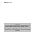
WARNING!!
NEVER APPLY POWER TO THIS AMPLIFIER WITH THE COVER REMOVED!
CONTACT WITH THE VOLTAGES INSIDE THIS AMPLIFIER CAN BE FATAL!
PLEASE READ THIS MANUAL BEFORE ATTEMPING TO OPERATE
EQUIPMENT! Improper or abusive operation of this amplifier can damage the tubes
or other components in this amplifier. Damage caused by improper or abusive
operation is not covered under the warranty policy.
i
AL-800H Instruction Manual
Unpacking Instructions
Remove the 3CX800A7 tubes from their shipping cartons. Carefully unwrap the tubes and inspect them for
visible damage. look for dented anode coolers and broken or bent pins. Roll the tubes over slowly and
listen for loose internal materials. contact either your Ameritron dealer or Ameritron immediately if any
damage exists.
Carefully lift the amplifier from the shipping carton, and place it on a firm, level surface. Inspect the
amplifier for shipping damage. contact either your Ameritron dealer or Ameritron immediately if any
damage exists. remove the cover screws with a #2 Philips screwdriver. Save the screws to resecure the
cover. carefully lift the rear of the cover while sliding the cover back. TheAL-800H is shipped with the
rubber chimneys, fusses, and fuse caps packed inside the amplifier. Additional screws will be included
in the fuse pack if they are required.
WARNING: Never remove the cover while this amplifier is connected to the power mains! Contact
with the voltages in this amplifier can be fatal.
The tubes must be installed in their sockets prior to operation. Observe the pin configuration on the tubes
and the sockets. Two of the pins are separated by a large space. Carefully observe the pin alignment to be
sure the tube pins are centered on the socket's metal contacts. Firmly press each tube into a socket. Do
NOT twist or force the tubes into the sockets.
Install the rubber chimneys over the tubes. The seam of the chimneys must face the fiber panel. The
bottom of the chimney has notches that must fit over the grid connectors near the base of the tube.
Remove the tape holding the anode connectors to the center panel. Install the anode spring clip connectors
on the tube's anode caps by pushing straight down on the clips.
The top cover should now be installed with the side ventilation holes positioned on the lift (front view).
The vent holes on the top of the cover should be on the right side of the amplifier (front view). Secure the
cover by installing the corner screw's first. Install all the screws loosely until every screw is in place.
Tighten the screws after they have all been installed.
Install the fuses and fuse caps on the back of the amplifier. This amplifier uses two 15A fuses for standard
240 Vac operation. If you wish to operate the amplifier on a line voltage other than 240 Vac, the jumpers
on the power transformer primary windings must be changed. If the line voltage wiring is changed, the
correct fuses must be installed. See the TRANSFORMER CONNECTIONS section on page 13 for more
information.
CAUTION:
Always use fast-blow fuses rated at 250 volts or higher.
automotive fuses or slow-blow fuses.
NEVER use standard
Note: Ameritron will NOT be responsible for shipping damage due to improper packing. The
packing materials used to ship this amplifier are specially designed to prevent damage. All packing
materials should be retained for future shipping. replacement packing materials may be purchased
from Ameritron if original packing materials are unavailable.
ii
AL-800H Instruction Manual
Table of Contents
Unpacking Instructions ....................................................................................................iv
Features............................................................................................................................1
AL-800H Technical Specifications .................................................................................2
General Information.........................................................................................................3
Safety Interlock....................................................................................................3
ALC .....................................................................................................................4
Dynamic Bias.......................................................................................................4
Timer - Overload Circuits................................................................................................5
Grid Overload Protection.....................................................................................5
Thermal Overload................................................................................................5
Cathode Warm-up Timer.....................................................................................5
Power Supply...................................................................................................................6
Heater Supply ......................................................................................................6
Plate (HV) Supply................................................................................................6
Meters ..............................................................................................................................6
Current Meter (plate and grid):............................................................................6
Multimeter ...........................................................................................................7
Multimeter Functions ..........................................................................................7
Wattmeter Circuit ................................................................................................7
Peak Envelope Power vs. Average Power ...........................................................8
Tube Life .........................................................................................................................8
Export Modifications.......................................................................................................9
Technical Assistance .......................................................................................................10
Installation Guidelines and Suggestions ..........................................................................11
Location Of The Amplifier .................................................................................11
Ventilation ...........................................................................................................11
Power Connections ..............................................................................................11
Grounding............................................................................................................12
Transformer Connections ................................................................................................13
Interconnections...............................................................................................................13
Operating Instructions And Guidelines ...........................................................................14
Front Panel Controls ............................................................................................14
"MULTIMETER" Switch........................................................................14
"OFF-ON" Switch....................................................................................14
"STBY-OPR" Switch...............................................................................14
"PLATE" Control ....................................................................................15
"LOAD" Control......................................................................................15
ALC Metering, Controls, and Adjustments .....................................................................15
ALC Metering Functions .....................................................................................15
ALC Controls.......................................................................................................16
ALC Adjustments ................................................................................................16
Rear-panel "ALC LIMIT" control .......................................................................17
ALC Limit Adjustment (rear panel) ....................................................................17
Driving Power..................................................................................................................18
Tube and Component Life ...............................................................................................18
iii
AL-800H Instruction Manual
Tuning..............................................................................................................................19
Tuning Procedure.................................................................................................19
"ALC SET" Control.............................................................................................22
Additional SSB Notes......................................................................................................22
AM (Amplitude Modulation) Operation .........................................................................22
FM (Frequency Modulation), RTTY, and DIGITAL OPERATION...............................23
Audio Distortion ..............................................................................................................23
QSK Operation ................................................................................................................23
Periodic Maintenance ......................................................................................................24
Parts List ..........................................................................................................................25
Power Supply / SWR Board (50-0800H-1) .........................................................25
Tuned Input Board (50-0800H-2)........................................................................26
AL-800H Tuned Input Chart ...............................................................................26
Meter Board (50-0800H-3)..................................................................................26
Timer / Overload Board (50-01172)....................................................................27
AL-800H Main Chassis Parts List .......................................................................28
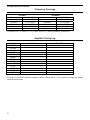
Frequency Coverage ........................................................................................................29
Amplifier Tuning Log......................................................................................................29
Notes:...................................................................................................................30
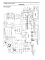
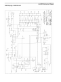
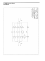
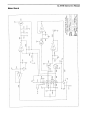
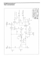
Schematics .......................................................................................................................31
Wiring Diagram ...................................................................................................31
PWR Supply / SWR Board..................................................................................32
Input Board ..........................................................................................................33
Meter Board .........................................................................................................34
Timer / Overload Board.......................................................................................35
Notes:...................................................................................................................36
iv
AL-800H Instruction Manual
Features
• The AL-800H uses two reliable high gain 3CX800A7 tubes.
• A time-delay circuit provides a 180 second warm-up to eliminate potential damage to the tube
cathodes.
• A grid overload circuit quickly disables the amplifier if the grid current becomes excessive. This
feature prevents excessive grid current from causing distortion or damaging the tubes or other
components.
• A thermal overload automatically disables the amplifier if excessive heating of the power transformer
occurs.
• A multi-voltage heavy-duty transformer with a unique "buck-boost" winding allows adjustment of
the primary voltage to 14 different voltages centered on 115 and 230 volts. This versatile Ameritron
feature allows the user to select the optimum primary voltage for maximum performance and life.
• The tuning and loading controls have vernier 6:1 reduction drives for smooth tuning. Logging scales
allow quick and repeatable control adjustment for rapid band changes.
• The AL-800H has two illuminated cross-needle panel meters. the left meter provides a continuous
reading of grid and plate currents. the right meter reads peak RF power output on one scale and Plate
voltage (HV), Reflected power and SWR (REF), ALC detector voltage (ALC), and ALC adjustment
level (ALC SET) on the other scales.
• Heater and plat voltages are maintained using the "STBY/OPR" switch. This allows the amplifier to
be conveniently bypassed for "barefoot" operation.
• A front panel "ALC SET" control allows convenient adjustment of the ALC threshold. The unique
ALC circuit samples the grid current and power supply voltage.
• "XMT" and "OL" LED's on the front panel indicate proper operation of the amplifier.
• A rear panel 12 volt auxiliary output jack provides up to 200 mA at 12 Vdc for accessories such as the
ART-15 Antenna Tuner.
• A step-start circuit limits the inrush current to the power supply and tube heater. This circuit extends
the life of the amplifier components.
1
AL-800H Instruction Manual
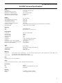
AL-800H Technical Specifications*
Input:
Circuit type:
Maximum VSWR at resonance:
Minimum 2:1 VSWR bandwidth:
Maximum drive power permissible:
Typical drive for full power output:
Pi-network, slug tuned coils
1.3:1 or less
20% of center frequency
100 watts PEP
55 watts
Output:
Circuit type:
Typical SSB PEP voice operation:
CW continuous operation:
1/2 hour PEP two-tone test:
1/2 hour continuous carrier (RTTY):
Frequency Coverage:
Third Order IMD:
Pi-L, Pi-network
1500 watts
1500 watts
1500 watts
1000 watts
1.8 to 21 MHz amateur Bands. (Export models include 24.5 and 28 MHz)
-35 dB or better (at rated output)
Efficiency:
CW:
SSB:
approximately 65%
approximately 65% (envelope crest)
Power Supply:
Circuit type:
No load voltage:
Full load voltage:
Full load current:
Regulation:
Transformer:
Capacitors:
Normal line current at rated CW output:
Normal line current at 1500 watt PEP output:
Power line current in standby:
Full wave voltage doubler
2600 V
2250 V
1.2 A
15%
32 lb. E-I lamination grain oriented
63 mFd total, computer grade
14A at 240 Vac
9 A at 240 Vac
0.5 A at 240 Vac
Tube:
Type:
Continuous dissipation:
Warm-up time:
Estimated life:
(2) 3CX800A7
800 watts total per tube, 1600 watts total
180 seconds
8,000 hours ICAS
Metering:
Multimeter:
Current meter:
Peak forward power (continuously). The second scale switches between peak reflected power (and SWR), ALC
threshold, ALC output voltage, and high voltage.
Plate and grid current (simultaneously) on separate scales.
ALC:
Negative going, 0 to 10 volts, adjustable.
Relay:
Requires contact closure or sink of +12 Vdc at 100 mA. Back pulse protected.
Connectors:
RF:
Line:
Others:
SO-239
NEMA 6-15P, standard 240 V three wire
RCA Phono
Physical:
Dimensions:
Weight:
17-1/4"D x 14-1/2"W x 8-1/2"H
60 lbs. shipping (52 lbs. operating)
2
AL-800H Instruction Manual
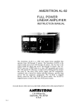
Ameritron Al-800H 1500 Watt Linear Amplifier Instruction Manual
The Ameritron AL-800H is a 1500 watt output linear amplifier that operates from 160 through 15 meters.
The AL-800HX is the export model that operate from 160 through 10 meters. Export modification
instructions are only available with proof of a valid amateur radio license.
The AL-800H uses a pair 3CX800A7 tubes in a class AB2 grounded grid circuit. High-quality power
supply and RF components combine with an accurate peak-detecting directional coupler, front panel
adjustable true ALC circuit, electronic grid current and thermal overload protection, and automatic bias
switching to make this the best featured and most reliable 3CX800A7 amplifier available. The AL-800H
and AL-800HX are factory-wired for 240 volt, 50/60 Hz ac line voltage. All models are easily converted to
other supply voltages between 90 and 250 volts ac.
General Information
Safety Interlock
The top cover of the AL-800H operates an interlock switch which completes the primary circuit of the
power transformer. The interlock will open and de-energize the transformer primary if the top cover is
removed.
WARNING: High voltage can kill!! Accidental contact with the voltages in this amplifier can be
lethal.
For your personal safety please observe the following precautions:
1.
2.
3.
4.
5.
6.
7.
3
NEVER defeat the interlock.
NEVER remove the cover with the amplifier connected to the power line.
ALWAYS allow the capacitors to discharge for several minutes after unplugging the amplifier and
before removing the cover.
ALWAYS select the high-voltage (HV) function of the Multimeter to check the high voltage potential.
Do not remove the cover if voltage is indicated.
ALWAYS ground the tube anode (outer metal surface) to the chassis through a low value, high
wattage resistor before touching anything inside the amplifier.
ALWAYS be cautious of heat. Many components inside the amplifier operate at high enough
temperatures to cause burns.
NEVER make any unauthorized component or circuit modifications to this product. The only
acceptable source for modifications is Ameritron or a source approved by Ameritron. Unauthorized
modifications almost certainly will increase the risk of equipment failure or personal injury.
AL-800H Instruction Manual
ALC
The AL-800H is one of the few amplifiers using a "true" automatic level control [ALC] circuit. In this
amplifier, the ALC actually samples grid current and power supply loading to determine the ALC voltage.
The front panel "ALC SET" knob adjusts the level of grid current where ALC action begins. The ALC
action begins softly over a range of a few milliamperes to minimize distortion. This soft-touch ALC is an
Ameritron exclusive.
The ALC circuit is located on the METER BOARD P/N 50-0800H-3 (behind the "MULTIMETER"
switch). IC301 (pin 9) samples the voltage drop (caused by grid current) across R106 in the main power
supply board. ALC voltage is derived by comparing the grid shunt voltage to the voltage from the power
supply (pin 10).
Pin 8 of IC1 will go negative if the grid shunt voltage exceeds the voltage from divider R311 and R2
(chassis mounted control), or if the supply voltage sags from excessive line voltage drop. Pin 8 is followed
by current buffer Q303 that sources the negative ALC voltage to the ALC output jack.
Dynamic Bias
Conventional bias circuits allow high power linear amplifiers to dissipate hundreds of watts during low or
no signal periods. This creates needless heat, since virtually no dissipation is required unless the amplifier
is being driven with large signal levels.
The AL-800H contains an exclusive bias circuit that reduces the idling (quiescent) current very close to the
tube's cut off region. The power amplifier tube in the AL-800H has a full resting period of very low
dissipation between dots and dashes on CW and between words on SSB. The lower idling current
dramatically reduces component temperatures on both CW and SSB. If only a few milliwatts of RF power
are applied to the amplifier, the quiescent current will increase. Linearity remains excellent with this circuit
because the tube's conduction angle is never reduced below class AB.
The dynamic bias circuit is located on the Power Supply Board P/N 50-0800-H1. Diodes D101 and D102
rectify a small sample of the RF drive voltage. This voltage is applied to the base of dc switch Q101. If
Q101's base is driven with a few microamperes of current from the RF sampling circuit, Q101's collector
will pull the base of PNP transistor Q102 low. This turns dc switch Q102 on.
When Q102 is on, zener diode D103 is connected between the collector and base of Q103.
D103 sets the operating bias. This zener applies forward bias to Q103's base whenever the collector voltage
of Q103 exceeds the voltage of D103. This forward bias will turn Q103 on harder and will reduce the
collector voltage. If the collector voltage is less than the breakdown voltage of D103, Q103 will move
towards cut-off and the collector voltage will increase. Q103 is, in effect, a current buffer for zener diode
D103.
4
AL-800H Instruction Manual
Timer - Overload Circuits
CAUTION:
Never modify or disable protection circuits without factory approval. Doing so with void
all manufacturer's warranties.
Grid Overload Protection
This amplifier contains a fast acting electronic grid protection circuit to enhance tube life. The amplifier
will quit operating and the "OL" and "XMT" LEDs will both illuminate if the safe limit of grid
dissipation is approached or exceeded. The grid overload protection circuit is reset whenever the "STBYOPR" switch is placed in the "STBY" position.
NOTE: This circuit has a much faster response time than the grid meter. This circuit also measures
the peak grid current. The operator may not observe the grid current meter climbing before
the overload circuit responds and disables the amplifier.
This circuit is located on the Timer / Overload board P/N 50-0800-5. IC501 (pin 5) senses the voltage
across the grid shunt (power supply board, R106) through terminal 1. If the voltage at pin 5 exceeds the
regulated voltage at the junction of R505 and R511, the output of IC501 (pin 7) will go high and turn on
Q504. Q504 will energize the coil of RL501. RL501 will latch "on" and remove the voltage from terminal
3 and relay RLY101 (power supply board).
Thermal Overload
The transformer in this amplifier contains an internal temperature sensor. This sensor disables the transmit
function if the transformer's temperature ever happens to approach the limit of safe operation. Thermal
overload is indicated if the "OL" LED illuminates without the "XMT" LED being illuminated.
The amplifier will not operate during a thermal overload indication. The thermal protection system
automatically resets after several minutes of a non-transmitting cool down period.
Cathode Warm-up Timer
Indirectly heated transmitting tubes normally require a few minutes of "warm-up" time before plate current
can be drawn. This protection is provided by IC501 (see TUBE LIFE on page 8). Pin 2 of IC501 is
connected to a regulated reference voltage. C509 begins to charge when the main power switch is placed in
the ON position. The voltage at pin 3 of IC501 will exceed the voltage on pin 2 after approximately three
minutes, causing the output of IC501 (pin 1) to go high.
Q503's collector pulls low whenever the output of IC501 (pin 1) is high. When the collector of Q503 is
low, Q502 and Q501 are forward-biased. This allows 12 volts to appear at terminal 5. Terminal 5 supplies
12 Vdc to the keying circuits and the plate and grid current meter lamp.
5
AL-800H Instruction Manual
Power Supply
Heater Supply
The heater circuit of this amplifier satisfies all requirements of the tube manufacturer related to tube
performance and life. The heater voltage and inrush current are controlled by the power transformer's
internal resistance and impedance, heater choke resistance, heater wiring resistance, and the step-start
circuit. For maximum tube life, NEVER replace any circuit components or wiring with substitute parts.
Always consult the factory before modifying any section of this amplifier
Plate (HV) Supply
The plate supply uses a full wave doubler circuit with 200 amp surge rated diodes and a heavy duty 32
pound grain oriented transformer with internal thermal protection. Filtering is accomplished by a bank of
high quality computer grade capacitors totaling 63 mFd. Large 50k-ohm 7-watt bleeders are used for safety
and superior voltage equalization. The transformer allows user selection of fourteen different line voltages
(See the TRANSFORMER CONNECTIONS section on page 13 for details).
Power is supplied through "OFF-ON" switch S2. A 10 ohm resistor (R27) limits the line current during
the filter capacitor charge time to lower component stress. When the filter capacitor charging current
decreases sufficiently, RLY102 shorts the 10 ohm resistor. This applies full power line voltage to the
transformer. The 10 ohm resistor is protected from high-voltage supply shorts by a two-ampere fast-blow
fuse (F101) during start-up. If F101 or the 10 ohm resistor (R27) fails the amplifier will not start. If F101
fails from a momentary HV to ground fault, meter protection diode D117 may also fail. See the METERS
section that follows for more information.
Meters
Current Meter (plate and grid):
The plate and grid current meter is located on the far left side of the front panel. This meter indicates the
plate current (Ip) on the right-hand meter scale. This scale has a small picket every 0.05 ampere, a large
picket every 0.25 ampere, and indicates 1.5 amperes at full deflection.
The left-hand meter scale indicates the grid current (Ig). The small pickets on this "Ig" scale appear every 5
mA and the larger pickets appear every 25 mA. The full scale "Ig" reading is 125 mA.
The plate and grid meters in this amplifier will normally indicate maximum grid current and maximum RF
output near the same "PLATE" tuning setting during adjustments. Maximum grid current and minimum
plate current also generally occur at or near the same "PLATE" tuning setting.
NOTE:
If the grid and plate meters always track (move together in exact step) as the tuning
controls are adjusted and if they show the same approximate amount of pointer movement,
diode D117 on the power supply board could be shorted.
D117 protects the overload circuit and the meters. This diode is located near the electrolytic capacitors on
outside edge of the main circuit board. D117 will usually short if there is a large high-voltage-to-chassis
current fault. The grid and plate current meters will not read correctly if this diode fails. The overload
circuit may repeatedly trip before full power is reached if D117 is shorted.
6
AL-800H Instruction Manual
Multimeter
The multimeter is the meter on the right. It continuously reads the forward peak envelope power on its lefthand scale (FWD). This scale is calibrated in 100 watt steps up to 2 kW.
The right-hand scale of this meter serves multiple functions, including measurement of the high voltage
(HV), reflected power (REF), SWR, ALC voltage output (ALC), and relative ALC threshold (ALC SET).
These four metering functions are selected by the "MULTIMETER" switch. See MULTIMETER
FUNCTIONS for more information.
Multimeter Functions
HV: The multimeter will indicate the dc plate voltage of the PA tube when in the HV position. The correct
scale to use is the ACL / HV scale, which has a picket every 100 volts. Two zeros must be added behind
the numbers indicated on the meter scale (i.e. multiply by 100), so that "25"=2500 volts and "20"=2000
volts. Do not operate the amplifier if the high voltage is over 2700 volts with the amplifier on standby. See
the TRANSFORMER CONNECTIONS section on page 13 for information on correcting excessive high
voltage.
REF: The multimeter measures the antenna (or load) peak envelope reflected power in the REF position.
The full scale reflected power reading is 500 watts. This scale is marked every 10 watts below 100 watts,
and every 100 watts from 100 to 500 watts.
NOTE: The SWR of the load can be measured when the "MULTIMETER" switch is in the REF
position by observing the different red SWR curves. The forward and reflected meter
pointers will cross each other on, or near, the correct SWR curve.
ALC: The multimeter measures the output voltage of the ALC detector when in the ALC position. The
full scale ALC reading is 35 volts and is read directly from the ACL / HV scale. The meter should flick
upwards occasionally during normal ALC action. See ALC METERING, CONTROLS, AND
ADJUSTMENTS operation on page 15 for more information.
ALC SET: The multimeter measures the approximate grid current that will produce ALC activity when
the meter switch is in the "ALC SET" position. One zero must be added to the reading on the ACL / HV
scale and the result divided by 2 for this function. For example, ALC action will begin at approximately 75
mA of grid current (typically between 60 mA and 90 mA) when the "ALC SET" control is adjusted until
the meter reads "15."
Wattmeter Circuit
The AL-800H wattmeter circuit uses an accurate directional coupler followed by a true peak detector
circuit. This circuit will accurately determine the true peak envelope power (PEP) of normal voice
waveforms. If the load SWR is high, the true power reading can be obtained by subtracting the reflected
power from the forward power reading.
7
AL-800H Instruction Manual
Peak Envelope Power vs. Average Power
Peak envelope power (PEP) is often misunderstood. PEP is not associated with the sine wave or root-meansquare (RMS) power, and it has no fixed ratio to average power. There are no formulas that allow accurate
conversions between average and peak voice waveform power.
PEP is the power at the crest (highest point) of the RF waveform. On SSB, the average power can vary
from a few percent of the PEP to over fifty percent of the PEP. Generally, the PEP on SSB is two to five
times greater than the average power. On CW or other constant amplitude modes (such as FM or RTTY),
the PEP is always equal to the average power.
Tube Life
The 3CX800A7 is a reasonably rugged tube. The anode can handle very large anode dissipation overloads
for short periods of time due to the thermal mass of the external anode. Care must be taken to avoid
exceeding the temperature ratings of the tube's ceramic-to-metal seals. The life of the tube in this amplifier
may be prolonged if adjustment periods are kept short and a brief "cool-down" periods are provided
between lengthy adjustment periods. Avoid shutting the main power off immediately after lengthy full
power CW or RTTY transmissions. After lengthy full power RTTY or CW transmissions, allow a one or
two minute "cool-down" period (without transmitting) before shutting off the ac power switch.
The most sensitive element in any indirectly heated oxide cathode tube will always be the control grid. A
fraction of a second of incorrect tuning can cause control grid damage. This is especially true in amplifiers
that use fuses or resistors to protect the grids. Fuses and resistors are much too slow and too unpredictable
to adequately protect control grids. The 3CX800A7 grids in this amplifier are protected by a fast-acting
electronic circuit. This circuit rapidly disables the amplifier when excessive grid dissipation occurs.
In the AL-800H a grid current of 150 mA (at 100 watts of drive) produces the maximum rated grid
dissipation of 4 watts per tube. This amount of grid current will also safely disable the amplifier within a
few milliseconds. Never remove or defeat the grid protection circuit. Doing so will void all
manufacture's warranties.
WARNING:
NEVER drive this amplifier with more than 100 watts of short term average envelope power.
NEVER remove, defeat, or modify the internal electronic grid protection circuits.
Maximum power output normally occurs with a maximum of 40 to 60 mA of grid current on CW, or 25
mA indicated (50 mA peak) during a SSB two-tone test. During typical SSB voice operation, the grid
current usually moves slightly above zero. The grid dissipation is well under one watt with 50 mA of grid
current and 100 watts of drive is around on watt per tube.
The cathodes of the 3CX800A7's must reach full operating temperature before the tube is operated. The
cathodes become fully operational 180 seconds after the application of the full heater voltage. The warmup timer in this amplifier assures that the cathode reaches the proper operating temperature before the
amplifier can be operated. Never defeat the warm up timer or alter the heater voltage.
8
AL-800H Instruction Manual
The continuous commercial plate current rating of each 3CX800A7 is 600 mA. Brief periods of plate
current exceeding 1.5 amperes (per pair) will not cause loss of emission or shorten the life of the tubes in
this amplifier. For maximum tube life, plate current should be maintained below 1.3 A on normal amateur
CW operation, 1.2 A on FM, RTTY, and other "steady" carrier modes.
The application of heater or filament voltage causes thermal stresses from rapid and uneven temperature
changes in the tube's heater. Avoid unnecessary main power switch cycling to prevent needless heater life
reduction.
An accumulation of gas (or stray debris) in the tube can cause the tube to arc between the anode and the
other elements of the tube. The resulting "gas arc" will generally manifest itself as a loud "pop" when the
amplifier is first turned on, or during conditions of high anode voltage. A "gas arc" will often damage diode
D117 on the negative rail of the filter capacitor bank and open the fuses in the amplifier. If this problem
occurs frequently, the tubes should be tested or replaced. The use of low quality tubes, tube that have been
stored for extended periods, or abused tube will increase the likelihood of a "gas arc". Ameritron
recommends using only current code date Eimac 3CX800A7 tubes.
Export Modifications
A simple modification will allow operation on frequencies above 15 meters. Instructions for this
modification are available by sending a written request for "Export Modification Instructions" along with a
copy of a valid amateur license. There is no charge for this information. Export models are shipped with
this modification installed and have an "X" or "Y" following the serial number. Standard frequency ranges
are indicated in the chart on page 19.
9
AL-800H Instruction Manual
Technical Assistance
Technical assistance is available during normal central standard time business hours on weekdays.
Customer service is more effective when our engineers are provided the following information:
1. Model and serial number
2. Date of purchase and dealer
3. An accurate description of the problem
Meter readings at all stages of the tuning procedure are very important along with a complete description of
the other equipment used with our product.
Written assistance is also available. Due to time delays in processing mail, please allow at least three
weeks for a written reply. For service or written correspondence, use the following address:
AMERITRON
116 Willow Rd.
Starkville, MS. 39759
Telephone (662) 323-8211
FAX (662) 323-6551
NOTE: Service history has clearly shown that most problems are operating or installation errors,
rather than equipment failures. Most problems can be resolved over the telephone. Please
contact our staff before shipping parts or equipment to us.
The packing materials used to ship this amplifier were specially designed to prevent shipping damage. The
original packing materials should be used to ship this amplifier. Replacement packing materials may be
purchased from Ameritron if original packing materials are unavailable or damaged.
CAUTION: Never ship this amplifier with the tube installed. Ameritron will not be responsible for
shipping damage caused by improper packing.
10
AL-800H Instruction Manual
Installation Guidelines and Suggestions
Location Of The Amplifier
Do not install the amplifier in excessively warm locations or near heating vents or radiators. Be sure air can
circulate freely around and through the amplifier cabinet. Provide an unobstructed cold air inlet for the
amplifier. DO NOT place any books, magazines or equipment that will impede the free flow of air near or
on the cabinet ventilation holes.
Ventilation
The AL-800H ventilation system has been designed and tested to maintain tube seal temperatures safely
below the tube manufacturer's rating at 1200 watts of continuous two tone test SSB PEP output, or 1500
watts of continuous two-tone or CW power output when the amplifier is properly tuned. The blower in the
AL-800H is a permanently lubricated type that requires no maintenance in normal operation. To insure
adequate cooling in your installation, please observe the following:
1.
Do not block or unduly restrict the ventilation holes in the cover. Be sure that the amplifier is located
in an area so the ventilation holes have open air circulation. It is particularly important to avoid
restricting the air inlet.
2.
The exhaust airflow is over 30 CFM. Do not "assist" the exhaust airflow with cabinet mounted fans.
3.
The most efficient way to improve airflow is to pressurize the air inlet area. Be sure that any fan used
to assist the inlet airflow has at least a 60 CFM rating.
4.
The exhaust air will become quite warm at high power levels. Do not place any heat sensitive objects
in the exhaust air stream.
Power Connections
The AL-800H is supplied with a NEMA 6-15P plug for 240 Vac operation. Full duty cycle operation with
ac supply voltages below 200 volts is not recommended. The TRANSFORMER CONNECTIONS section
on page 13 show the correct wiring for various supply voltages.
This amplifier has a current demand of approximately 14 amperes at 240 Vac with 1500 watts of RF carrier
output. The average power line current during voice peaks on SSB will be approximately 9 amperes at
1500 watts PEP output. Most normal residential power lines and house-wiring should meet this demand for
current.
If the power mains have excessive resistance, the high voltage may sag to less than 2200 volts under load.
Voltage sag will not hurt the amplifier if the fully loaded high voltage remains above 2000 volts.
CAUTION: Never allow the high voltage to exceed 2700 volts under any condition.
For 240 volt operation, the wiring between the fuse box and the amplifier ac outlet must be number 14
gauge (or larger) in order to supply the current required (14 A) without a significant drop in the line voltage.
The 240 volt outlet should be fused 20 amperes.
11
AL-800H Instruction Manual
Grounding
Connect a good RF and dc ground to the ground post on the rear panel of the amplifier. Use the heaviest
and shortest connection possible. The best materials to use for ground connections are (in order of
effectiveness) smooth wide copper flashing, copper tubing, or solid copper wire. Never use braided or
woven conductors unless the lead needs to be flexible. Braided or woven conductors offer a high
impedance to both lightning and RF.
Water pipes, metal heating ducts, metal fences and other large metallic masses offer convenient RF
grounds. If a water pipe ground is used, inspect all the pipe connections to be sure that no plastic or rubber
connections are insulating the pipes. Insulated pipe connections will interrupt the electrical continuity to
the water supply line. Install a jumper around any insulated pipe connections you find. Use heavy copper
wire or flashing with stainless hose or pipe clamps for the jumpers.
The following tips will help prevent lightning damage and RF grounding problems:
1.
Avoid using braided or woven conductors, they have very high resistance to both RF and lightning
currents. RF and lightning flows along the surface of conductors, almost no current flows in the center
of the conductor. The lowest RF resistance occurs with wide, smooth conductors.
2.
Avoid routing a single small gauge grounding conductor along the various pieces of equipment (or to
connect multiple ground sources). Instead, use multiple ground leads that connect to a single wide
buss at the operating position. Keep all ground leads as short and wide as possible.
3.
Buried radials provide much better lightning and RF grounds than ground rods do, although both are
needed for safety.
4.
Avoid sharp bends in ground leads. When changing the direction of a ground lead use a gradual radius
turn.
5.
Avoid second story operation. A good ground is much easier to obtain on the first floor or in the
basement of a structure.
6.
Air-core choke baluns should be used on all coaxial feedlines. The feedlines should be coiled into
several 4" to 6" diameter turns before they enter the building. Either directly bury the feedlines a few
inches deep in the ground for a minimum distance of ten feet or ground the shields to a separate
outside ground on the antenna side of the choke.
12
AL-800H Instruction Manual
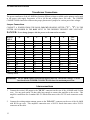
Transformer Connections
The power transformer of the AL-800H has fourteen different voltages available on the primary and is rated
at full power with supply frequencies of 50 to 60 Hz and voltages above 200 volts. The JUMPER
CONNECTIONS chart below indicates the proper placement of jumpers for various power line voltages.
Jumper Connections
CONNECT A JUMPER FROM THE BOLD COLUMN HEADING LETTER ("A" - "F") TO THE
LETTER OR NUMBER IN THE ROW NEXT TO THE DESIRED "HIGHEST LINE VOLTAGE".
DANGER: Never change jumpers with the power cord connected to an outlet.
Highest
"A"
Line-V
205
215
220
230
240*
245
250
90
(B)
100
(B)
110
(B)
115
(B)
125
(B)
130
(B)
140
(B)
* Factory wired
"B"
C
C
C
C
C
C
C
A
A
A
A
A
A
A
"C"
(B)
(B)
(B)
(B)
(B)
(B)
(B)
(D)
(D)
(D)
(D)
(D)
(D)
(D)
"D"
C
C
C
C
C
C
C
"E"
3
3
2
F
1
2
1
3
3
2
F
1
2
1
Line
Fuse
"F"
1
2
1
(E)
2
3
3
1
2
1
(E)
2
3
3
20
20
20
15
15
15
15
20
20
20
20
20
20
20
WARNING: The AL-800H requires different back panel fuses for various line voltages. Use the
fuse listed in the JUMPER CONNECTIONS chart for maximum protection.
Interconnections
1.
Connect the exciter's RF output to the "RF IN" connector on the rear of the AL-800H with 50 ohm
coax. Use any good quality 50 ohm cable long enough to connect the amplifier to the exciter. This
amplifier connection uses a standard SO-239 female that mates with a PL-259 male connector on the
cable.
2.
Connect the existing station antenna system to the "RF OUT" connector on the rear of the AL-800H
with RG-8 type coax. This amplifier connection uses a SO-239 female that mates with a PL-259
connector on the cable.
13
AL-800H Instruction Manual
3.
Shielded audio type cable with a standard male phono plug should be used to connect to the "RLY"
jack on the AL-800H. This jack has positive 12 Vdc open circuit and supplies 100 mA of current
when pulled to ground. The relay circuit has an internal back pulse canceling diode to protect sensitive
exciter circuits from damage.
4.
Connect a short, wide, and smooth ground lead from a good earth and RF ground to the rear panel
"GND" terminal. Avoid using braided conductors for ground leads.
5.
The "12 V" connection on the rear panel provides 12 Vdc at 200 mA maximum to operate external
dial lamps or accessories such as the ATR-15 Antenna Tuner.
6.
Connect the "ALC" jack to the ALC input of the exciter with a shielded cable and a phono plug. The
proper connection point on the exciter should be indicated in the exciter's manual. The AL-800H ALC
will operate with any exciter that uses a negative-going ALC voltage of up to 10 volts.
Note: Transceiver ALC response times and ALC voltage requirements vary with different
manufacturers. The ALC section describes adjustment of this circuit in detail.
Operating Instructions And Guidelines
Front Panel Controls
"MULTIMETER" Switch
This four position switch selects either the plate voltage (HV) of 0-3500 volts, the reflected peak envelope
power (REF) of 0-500 watts, the ALC detector output voltage (ALC) of 0-35 volts, or the approximate ALC
grid current threshold (ALC SET) of 0-175 mA. See the METERS section on page 6 for more details.
"OFF-ON" Switch
This switch turns the main power off and on. When this switch is placed in the "ON" position the blower
should start, the right-hand meter should be illuminated, and high voltage should appear. The left-hand
meter should illuminate and the amplifier should operate after three minutes.
"STBY-OPR" Switch
This switch disables the amplifier's internal antenna relay and resets the grid protection circuit. In the
"STBY" position the amplifier is bypassed without turning the tube's heater or the power supply off.
This switch will also reset the grid protection circuit if the "OL" LED is illuminated. The overload circuit
is automatically reset whenever this switch is placed in the "STBY" position and returned to the operate
position.
14
AL-800H Instruction Manual
"PLATE" Control
The "PLATE" control adjusts the output tank circuit to resonance. This control should always be adjusted
for maximum RF output power. Maximum RF output power normally occurs simultaneously with
maximum grid current and very close to the plate-current "dip."
"LOAD" Control
This control adjusts the coupling of the amplifier to the antenna. This adjustment is necessary to insure
optimum coupling to the load as the SWR of the load, the operating frequency, or the power level is
changed. Advancing the "LOAD" control clockwise increases the RF power output capability and the
linearity of the amplifier. Advancing the "LOAD" control also decreases the grid current and increases
the plate current for a given amount of drive.
The efficiency of the amplifier and the grid current decrease if the "LOAD" control is rotated beyond the
point of maximum output. The linearity, however, will increase. The proper position for this control is
slightly clockwise from the setting that produces maximum output with full drive-power applied. Never
use this control to adjust the output power.
CAUTION: Failure to adjust the loading control properly can result in excessive tank circuit
voltages and damage to components.
The "PLATE" control should always be checked after the "LOAD" control is adjusted by more than one
number. For example, if the "LOAD" is advanced from 1-1/2 to 2-3/4, the "PLATE" should be re-tuned.
If the "LOAD" is touched up a small amount, the "PLATE" setting will not usually require re-adjustment.
ALC Metering, Controls, and Adjustments
ALC Metering Functions
The "MULTIMETER" switch in the AL-800H has two positions that indicate the functioning of the ALC
circuit. These positions are as follows:
ALC...In this position the multimeter measures the output voltage of the ALC detector. The full scale
reading of the ALC detector voltage is 35 volts. It is read directly from the "ACL / HV" scale of the
multimeter. The multimeter will indicate the maximum value of ALC voltage available from the internal
ALC circuit. The meter should flick upwards occasionally during normal ALC action in this position.
ALC SET...In this position the multimeter measures the approximate grid current that will produce ALC
activity. One zero must be added to the reading on the "ACL / HV" scale and the result divided by 2 for
this function.
For example: If the meter reads 15, add one zero (150) and divide by 2 (75). In this example ALC action
will begin at approximately 75 mA of grid current.
15
AL-800H Instruction Manual
ALC Controls
The position of the "ALC SET" control determines the grid current value that will begin to produce ALC
voltage. Rotating the "ALC SET" control counter-clockwise reduces the maximum grid current
obtainable and the available RF power output. Rotating the "ALC SET" control clockwise increases the
maximum grid current level.
The approximate grid current available before ALC action begins can be determined by placing the
"MULTIMETER" switch in the "ALC SET" (far clockwise) position. The "ALC SET" control should
normally be adjusted to produce a multimeter reading of 3 to 6 volts with the "MULTIMETER" switch in
the "ALC SET" position. This will allow a maximum grid current of approximately 15 to 30 mA.
ALC Adjustments
During SSB operation, two adjustments affect the ALC and the sound of the signal. One is the exciter's
microphone gain (or RF output level) adjustment. It will control the "fullness" of the ALC and the average
output power. It will have very little effect on the peak output power, however. The fullness of ALC action
is indicated by the meter reading in the multimeter "ALC" position. More exciter audio gain or power
output will drive the amplifier's ALC circuit harder, and produce a more constant meter reading. This
produces RF compression that increases the "talk power" without increasing signal bandwidth or distortion.
Note: Audio background noise will increase while using heavy ALC levels on SSB. Objectionable
background noise levels may occur while using heavy amounts of ALC, especially if the heavy ALC levels
are used in conjunction with other speech processing. In these situations, operating in a quiet room and
"close talking" the microphone will minimize objectionable background noise.
The amplifier's "ALC SET" control determines the level of grid current that produces ALC activity. The
maximum power output level. This amplifier has the best linearity when the "ALC SET" control is
adjusted to limit the peak grid current to 40 mA or lower. This adjustment must be made with a carrier or
single tone signal. When the "ALC SET" control is properly adjusted, it will be impossible to exceed 40
mA of grid current with any tuning or drive adjustment.
During CW operation, the "ALC SET" control voltage should be adjusted just high enough (clockwise)
to allow the desired output power to be reached. The "ALC SET" control should never be adjusted to the
point where the grid current can exceed 50 mA under any tuning or drive adjustment condition. During
proper CW ALC operation, the exciter drive level control should be adjusted until the ALC voltage meter
slightly flickers (ALC position of the "MULTIMETER" switch) while operating with normal output
power levels.
The ALC circuit will limit the amplifier's grid current to a safe value if anything accidentally changes in the
station or the antenna. The CW keying waveform of the radio will remain unaltered when the ALC is
adjusted in this manner.
Note: Caution should be exercised if the "ALC SET" is used to control the CW power output with
the exciter power control set at maximum. Key clicks may be produced if the exciter has a
poor ALC response time. Check for proper wave shape when using the ALC in the amplifier
exclusively to control the RF output power.
16
AL-800H Instruction Manual
Rear-Panel "ALC LIMIT" Control
The "ALC Limit" control (rear panel) limits the maximum voltage available from the ALC circuit. This
control is necessary only because the ALC response times and voltage requirements for exciters have never
been standardized. The ALC voltage requirements may even vary between different models produced by
the same manufacturer.
If the ALC response time of the exciter (transceiver) is faster than the rise time of the RF envelope, there
will be no voltage compatibility problems. The ALC voltage from this amplifier will automatically adjust
to the limit required by the exciter.
If the ALC voltage requirements are low and if the ALC attack time is slow, the ALC may cause the output
power to "pump" at a very slow rate. The undesired "pumping" can be corrected by reducing the amplifier's
ALC output voltage with the "ALC Limit" control (R1).
A full counter-clockwise "ALC Limit" setting will produce approximately 10 volts of maximum negative
ALC voltage. A full clockwise setting (viewed from amplifier rear) will produce no ALC voltage. Always
start with this control fully counter-clockwise before slowly advancing this control clockwise. The ALC
LIMIT ADJUSTMENT section that follows gives adjustment details.
An external 1,000 to 5,000 ohm potentiometer can be added from the ALC output line to ground if the
particular amplifier you are using does not have a rear panel "ALC Limit" control. The chassis (shield) of
the amplifier's ALC output jack must connect to the clockwise (shaft end view) terminal of the ALC exciter
voltage control. The ALC jack center pin on the amplifier must connect to the counter-clockwise terminal
(shaft end view) of the external control. The center of the control connects to the ALC input of the exciter.
ALC Limit Adjustment (rear panel)
This adjustment procedure should be used if "pumping" occurs from excessive transceiver ALC sensitivity
and/or slow transceiver ALC response time:
1.
Load the amplifier for maximum output on any band (see tuning instructions later in this manual).
2.
Adjust the "ALC SET" control on the front panel and the rear panel "ALC Limit" potentiometer to
their full counter-clockwise positions.
3.
Apply full exciter drive power, and adjust the rear panel "ALC Limit" potentiometer clockwise (rear
view) until the amplifier's ALC output voltage meter (multimeter "ALC" position) indicates 6 to 10
volts. As an alternative, the potentiometer can be adjusted clockwise until the RF output power
reaches 300-500 watts.
17
AL-800H Instruction Manual
Driving Power
This amplifier is designed to operate at full ratings when it is driven by an exciter that has approximately 70
watts of RF output. An exciter with a lower output power may be used with a resulting decrease in
amplifier output. Both the driving power and the "LOAD" control must be carefully adjusted when using
an exciter that delivers more than 70 watts. Proper control settings will help prevent excessive grid current
and spurious signals, which create needless interference to other operators. A monitor scope is
recommended for continuous output observation. An oscilloscope is the best way of determining if the
amplifier is "flat-topping" and producing excessive distortion products.
A second method of determining linear operation is to monitor the peak RF output power carefully on the
AL-800H's internal meter. Determine the maximum obtainable RF output power and reduce the exciters
power until there is a noticeable margin from the maximum output power. This will insure some reserve
power is available for random voice peaks.
Note: Never increase the drive power beyond the point where the amplifier's output power stops
increasing. This is also the point where the grid current will begin rising rapidly. If this
happens, the LOAD control is set too far counter-clockwise and needs to be adjusted to a
higher number.
The amplifier being over-driven for a given "LOAD" setting when the grid current increases rapidly while
the plate current and output power increase slowly. The amplifier "LOAD" control needs to be advanced
to a higher number if this condition occurs. Non-linear operation, splatter, and excessive grid current will
occur if the "LOAD" setting is too low. Excessive plate current is the proper indicator that the drive
power, while excessive grid current indicates improper loading.
Tube and Component Life
These guidelines will help prolong tube and component life, and minimize splatter.
1.
On SSB or other linear modes virtually any amount of power will cause splatter if the loading is too
light ("LOAD" control too far counter-clockwise). Always tune for maximum output with maximum
drive power. Reduce the drive power to reduce the output power on SSB, not the loading control.
2.
Lightly loading an amplifier will also result in large voltages building up in the tank circuit. Underloading an amplifier is much harder on the tube and other components than operating a properly loaded
amplifier into a high SWR or with excessive drive power.
3.
Never depend on average reading power or current meters to indicate proper operation on SSB or other
linear modes. The best indicator of linearity is either an oscilloscope or the internal PEP RF output
meter. Maximum linearity can be determined by finding the maximum output power possible and then
reducing the exciter power for a slight reduction in output power.
4.
Never exceed 60 mA of grid current on CW carrier. The proper grid current during voice modulated
SSB will range from 0 to 20 mA. The SSB grid current will vary with the operators voice, the amount
of signal compression or processing, and the tube characteristics.
18
AL-800H Instruction Manual
Tuning
Follow the instructions below in numerical order. Proper tuning will produce excellent output power, a
clean signal, and good tube life. If the various meter readings are different than indicated in the text, check
the external amplifier connections. Consult the manual for the exciter if necessary.
WARNING: The transformer must be wired correctly for your line voltage. This amplifier is
normally shipped wired for standard 240 Vac operation.
Connections section on page 13 for details.
See the Transformer
Tuning Procedure
Important Note: This amplifier contains an electronic grid protection circuit to prevent control-grid
damage. This amplifier will quit operating and the "OL" LED will illuminate if the grid dissipation
exceeds a safe pre-set limit. The overload circuit responds much faster than the grid current meter. The
overload circuit will respond to excessive grid current before the operator can observe the increase on the
grid current meter.
Some exciters generate high-level RF pulses when first keyed. These short duration pulses may greatly
exceed the exciter's steady-state operating output power. Unexplained activation of the grid overload
circuit may indicate the existence of this exciter problem. The grid overload circuit can be reset by
momentarily placing the "STBY-OPR" switch in the "STBY" position.
Never under-load the amplifier to reduce the output power. The amplifier "LOAD" control must be set to
a high enough position (clockwise) to prevent excessive voltage and arcing in the tank circuit or excessive
grid current. Repeated tripping of the grid overload circuit probably indicates the "LOAD" control is set
too low.
1.
Set the AL-800H front panel switches as follows:
POWER
OPR-STBY
MULTIMETER
to
to
to
OFF
STBY
HV
2.
Plug the ac line cord into the proper voltage outlet.
3.
Place the main power switch in the "ON" position. The meter lamps should light and the blower
should start. Read the 3500 volt scale on the multimeter. It should indicate 2600 volts nominal and no
more than 2700 volts.
4.
With the amplifier still on "STBY", tune the exciter into a normal 50 ohm load according to the
manufacturer's instructions. Turn the exciter drive down after tuning.
19
AL-800H Instruction Manual
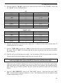
5.
Place the amplifier's "BAND" switch on the same band as the exciter. Set the "PLATE" control and
the "LOAD" control as indicated below:
Frequency
1.810
3.600
7.050
10.125
14.050
18.125
21.050
24.900
28.050
Frequency
1.850
3.900
7.200
14.250
21.350
28.500
CW
Plate
3-1/2
1-3/4
5
5-1/2
8
8
9
8-1/2
9
PHONE (SSB)
Plate
3-1/2
3
5-1/4
8-1/4
9-1/4
9
Load
6-1/4
0-1/2
1-3/4
2-1/2
6
5-1/2
6-1/2
6-1/2
7-1/2
Load
7
3-1/2
4-3/4
6
6-1/2
7-1/2
6.
With the exciter's drive level still on zero, observe the 1.5 ampere Ip scale on the left hand meter. It
should indicate zero (0) amperes.
7.
Place the "STBY-OPR" switch in the "OPR" position. Place the exciter in the transmit mode with no
RF output. The red "XMT" LED should light and the plate current (Ip on the left meter) should be
close to zero (0).
8.
With the exciter in the transmit mode, apply a very low amount of RF drive power (about 100 mW).
The plate current (Ip) should suddenly jump from zero to nearly 100 mA.
NOTE: Currents may vary up to 25% due to component and line voltage tolerances. If the current
in this step is higher than expected, the RF level from the exciter may be too high.
If the exciter does not allow adjustment to very low CW power levels, the exciter can be placed in the
SSB mode and the audio (microphone) gain control advanced from minimum while speaking until the
plate current (Ip) just flickers upwards. The plate current (Ip) should be around 100 mA on these
flickers.
9.
Place the "MULTIMETER" switch in the "ALC SET" position. Adjust the front panel "ALC
SET" control until the multimeter indicates 10 volts. This adjustment will limit the amplifier's grid
current to approximately 50 mA.
20
AL-800H Instruction Manual
>
STEPS 10a AND 11a REQUIRE A CONNECTION FROM THE AMPLIFIER'S ALC OUTPUT TO
THE EXCITER'S ALC INPUT.
>
STEPS 10b AND 11b SHOULD BE USED IF THE EXCITER AND AMPLIFIER ALC LINES ARE
NOT CONNECTED.
NOTE: Step number 10 requires the simultaneous observation of the plate current (Ip) and the grid
current (Ig).
10a. If the ALC line is connected, adjust the exciter's drive or power output control to maximum. NEVER
ALLOW THE GRID CURRENT (Ig) TO EXCEED 75 mA OR THE PLATE CURRENT (Ip) TO
EXCEED 1.2 AMPERES AT THIS STAGE OF TUNING. If either current exceeds these limits, reduce
the "ALC SET" control. Adjust the "PLATE" control for maximum output power. The plate current
(Ip) of the amplifier and the output power of the exciter should dip (decrease) when this adjustment is
made.
10b. If the ALC is not connected, place the exciter in the transmit mode and gradually increase the drive
until a grid current of 50 mA or a plate current of 0.5 ampere (whichever is higher) appears. The
"PLATE" control should be adjusted until maximum grid current and maximum RF output power
appear. The plate current (Ip) should now dip slightly. The drive power should be removed.
11a. Increase the "ALC SET" voltage (if the ALC is connected) until 70 mA (14 volts) is indicated. Apply
full drive (not to exceed 100 watts) and adjust the "LOAD" and "PLATE" controls for maximum RF
output power. The grid current should not be allowed to go above 100 mA at this stage. The plate
current should not be allowed to exceed 1.5 ampere during brief periods of tuning (30 seconds).
11b. Increase the exciter drive power (if the ALC is not connected) until 70 mA of grid current is indicated.
Adjust the "LOAD" and "PLATE" controls for maximum RF output power. The grid current should
not be allowed to go above 100 mA at this stage. The plate current should not be allowed to exceed
1.5 ampere during brief periods of tuning (30 seconds).
12. For CW operation, the output power should be reduced with the "ALC SET" control until the rated
power of 1500 watts CW is obtained. The "LOAD" control should be adjusted until minimum plate
current is obtained without dropping below 1500 watts. The exciter's power can be reduced until the
multimeter shows a slight upward flicker with the "MULTIMETER" switch in the ALC position if
the ALC is used.
13. For SSB operation, a two-tone generator or sustained "HEL-L-L-L-L-O" can be used. The exciter
should be set to produce the maximum output power (not to exceed 100 watts of average power). The
amplifier's "LOAD" control is adjusted for maximum power on the internal peak reading RF
wattmeter. The "ALC SET" control is adjusted until a peak power output of 1500 watts (or less) is
obtained. Finally the exciter's audio gain or output power is adjusted until the multimeter "ALC"
position indicates the desired ALC level.
NOTE: If the ALC is not connected, the amplifier should be fully loaded with maximum drive (not
to exceed 100 watts). The exciter's output should then be reduced until 1500 watts is
obtained.
21
AL-800H Instruction Manual
"ALC SET" Control
Proper adjustment of the front panel "ALC SET" control accomplishes the following:
1.
The exciter's power is limited to a value that will produce a fixed amount of grid current in the
amplifier. The front panel "ALC SET" control determines the maximum grid current that can be
produced.
2.
The "LOAD" control setting will determine the maximum plate current and output power for a given
grid current. Never exceed 1.5 A of short duty cycle (or 1.2 A of long duty cycle) plate current. Never
exceed 50 mA of operating grid current.
3.
For normal SSB operation, the exciter power should be reduced until the ALC voltage (measured in the
ALC multimeter position) flicks upwards on occasional voice peaks. This will produce the best audio
quality. The drive can be increased for DX or weak signal SSB operation until the ALC steadily
registers voltage.
Also see the ALC section on page 4, and the MULTIMETER section on page 7.
Additional SSB Notes
The peak power output developed on SSB is limited by the amplifier loading, RF drive, and peak-toaverage power of the RF wave form. The "LOAD" setting is the single most critical adjustment for proper
operation. Properly loaded, this amplifier will produce excellent linearity with output powers of well over
one kilowatt. Improperly adjusting the "LOAD" control can produce flat-topping and splatter with only a
few hundred watts of RF output.
NOTE: Always remember that the "LOAD" control setting is much more important than any other
parameter for good linearity!
To maintain linearity, always be sure that the "LOAD" control is adjusted far enough clockwise for the
peak drive that will be applied.
Be considerate of others. NEVER "push" this amplifier into envelope clipping or to the point where the
grid current approaches 25 mA on voice peaks. Envelope clipping can be also be avoided by adjusting the
amplifier's "ALC SET" control until the peak output power drops slightly from the power obtained with
full microphone gain and a fully clockwise "ALC SET" adjustment. For the cleanest audio, the
microphone gain can be reduced until the ALC meter just flickers on voice peaks.
AM (Amplitude Modulation) Operation
The efficiency of any conventional linear amplifier must remain below half the peak efficiency under
maximum signal conditions (less a safety factor) in AM operation. Since this linear amplifier has a peak
plate efficiency of nearly 65%, the carrier efficiency must be kept below 30% to maintain linearity. The
power dissipated in the tube anode will be more than twice the carrier output power.
The carrier power must be kept below 300 watts for clean and safe AM operation. With 300 watts of
carrier, the peak envelope power will reach 1200 watts with 100% symmetrical modulation. The modulated
AM power output should be limited to 1500 watts peak with non-symmetrical modulation that enhances the
positive peaks.
22
AL-800H Instruction Manual
FM (Frequency Modulation), RTTY, and Digital Operation
The efficiency of this amplifier will approach 65% in the FM, RTTY and DIGITAL OPERATION modes.
Since these modes do not require linear amplification of complex waveforms, the tuning can be re-adjusted
for maximum power at the desired output power level. This will keep the efficiency as high as possible.
Audio Distortion
One problem that often occurs when using a linear power amplifier is SSB audio distortion on one or more
bands. This distortion is usually caused by RF feedback from either a poorly designed antenna or poor RF
grounding. REMEMBER THAT A GOOD GROUND FOR DC IS NOT NECESSARILY GOOD FOR RF.
RF circuits require short connections with smooth, wide conductors. Braiding or woven wire has a very
high RF resistance and should be avoided. See the "Grounding" section on page 12 of this manual. More
detailed suggestions on grounding are available by requesting Ameritron's Tech Bulletin on RF Feedback.
QSK Operation
The antenna transfer relay in the AL-800H takes approximately 15 milliseconds to change states. This
precludes using the standard internal relay for QSK CW operation. Commonly available vacuum relays are
specified at 5 to 7 milliseconds of switching time. Even expensive vacuum relays are less than ideal for
high speed QSK operation. At 60 WPM, less than 50% of the receive-time is available with vacuum relays.
On PACKET, AMTOR, and other modes, delay can be added to the transmit and receive changeover to use
either vacuum or our standard relay effectively. Ameritron offers two high-speed PIN diode options that
permit operation on modes requiring high speed receive-transmit switching. Both systems offer noiseless
switching times of under one millisecond. Since these PIN diode systems are several times faster than
vacuum relay systems, they will allow over 90% of the available receive time to be used at 60 WPM.
Ameritron highly recommends using the external QSK-5 switch. This stand alone PIN diode switch can be
used with almost all types of amplifiers and transmitters. Modifications are not required in amplifiers used
with the QSK-5 unit. The QSK-5 operates directly from 120 Vac power lines.
Ameritron also offers an internal QSK board as a space-saver for the AL-800H. This internal board is
slightly less expensive. However, it provides less flexibility and serviceability than the external QSK-5
unit. Factory installation of the QSK-5PC is highly recommend. Contact Ameritron for details on the
QSK-5 and the QSK-5PC.
23
AL-800H Instruction Manual
Periodic Maintenance
The high voltage present on various parts of the amplifier will attract dust and dirt. The high voltage areas
at the bottom of the plate choke and the plates and insulators of the air variable capacitors should be kept
dust free. These areas should be inspected periodically, especially if the amplifier is operated in a dusty
environment. These areas may be inspected by unplugging the line cord and waiting a few minutes for the
power supply capacitors to discharge. The high voltage should then be checked with the internal
multimeter by placing the meter switch in the HV position.
WARNING: High voltages can kill!!! Accidental contact with the voltages in this amplifier can be
lethal!
For your personal safety please observe the following precautions:
1.
2.
3.
4.
5.
6.
7.
NEVER defeat the interlock.
NEVER remove the cover with the amplifier connected to the power line.
ALWAYS allow the capacitors to discharge for several minutes after unplugging the amplifier and
before removing the cover.
ALWAYS select the high-voltage (HV) function of the Multimeter to check the high voltage potential.
Do not remove the cover if voltage is indicated.
ALWAYS ground the tube anodes (outer metal surface) to the chassis before touching anything inside
the amplifier.
ALWAYS be cautious of heat. Many components inside the amplifier operate at high temperatures.
NEVER make any unauthorized component or circuit modifications to this product. The only
acceptable source for modifications is Ameritron or a source approved by Ameritron. Unauthorized
modifications almost certainly will increase the risk of equipment failure or personal injury.
The cover should be removed and a low value (40 to 500 ohm) two-watt or larger resistor should be secured
to the chassis. The other end of this resistor should be connected to the tube anode with an insulated clip
lead.
CAUTION: NEVER ground the anode directly to the chassis without a series resistor. Component
damage may occur from the current surge.
NOTE: This resistor is a safety device that must be installed when beginning service work and
removed when the work is finished.
Dust and dirt can be blown out of the amplifier with a shop vacuum or a high-pressure air hose. A soft
bristle brush dipped in alcohol can be used to clean particularly dirty areas. If the amplifier is operated in a
dusty environment, a non-conductive low- restriction foam air filter can be placed over the ventilation
holes on the left side of the cabinet near the filter capacitors. Placing an air filter over these air inlet holes
will substantially reduce the amount of dust entering the cabinet. Most hardware stores stock suitable air
filter material that are used as replacement filters for window air conditioners.
24
AL-800H Instruction Manual
Parts List
Power Supply / SWR Board (50-0800H-1)
Designator
D101, 102, 114, 115
D103
D116 - 120
D104 - 113
C101
C102,105
C103
C104
C106,125,126,129,135 - 137
C140
C107 - 116
C118 - 123
C127
C128, 132, 138, 139, 140
C130, 131
C133
C134
R101
R102
R103,104,121
R105
R106
R107,131
R108,109
R110,111
R113-118
R120
R122
R123
R124,125
R126, 128, 129
R127
R130
RLY101
RLY102
RFC101
T101
Q101
Q102
Q3 (see main chassis)
F101
25
Description
1N34A
1N752 Zener 5.6V
1N4001
1N5408
27 pF 500 V
.001 uF 1 kV
10 pF 1 kV
3-12 pF 500 V Trim
.01uF 50 V Disc
.47 uF
.01 uF 1 kV
380 uF 450 V Elect.
270 pF 500 V
.1 uF 50 V
.01 uF 250 Vac
2200 uF 25 V
220 uF 25 V
4.7k mox 1 W
470k 1/4 W
10k 1/4 W
10 ohm 1/2 W
3 ohm 2 W 1%
0.6 ohm 3 W 1%
1M 3 W 1% special high voltage type
750k 2 W mox 2%
50k 7 W 5%
51 ohm 2 W mox 5%
6.8k 1/4 W
1.8k 1/4 W
50k trim pot
47k 1/2 W
10 ohm 10 W
47 ohm 1/2 W
3PDT 12 Vdc
SPST 12 Vdc
Choke 3 turns FB-73
Toroid
2N3904
2N3906
MFJ3055 transistor, NPN
2 A slow blow
Ameritron P/N
300-0346
305-0710
300-0266
300-0145
208-5404
200-2120
200-3531
204-0150
200-0416
203-0530
200-2121
203-0682
208-5775
200-0754
200-2122
203-0207
203-0565
103-1747
100-0188
100-4100
100-0727
103-3400
103-3399
103-2223
103-1743
103-7580
103-2151
103-1747
100-0728
104-0400
101-0402
103-9702
101-4470
408-6140
408-6148
10-15168
10-14134
305-0645
305-0722
305-3055
755-1102
AL-800H Instruction Manual
Tuned Input Board (50-0800H-2)
Designator
C201 (tube side)
C202 (transmitter side)
C213
C214
C215
L201
S201
Description
See input chart
See input chart
150pF capacitor
150pF capacitor
220pF capacitor
See input chart
Input switch
Ameritron PN
See input chart
See input chart
208-5151
208-5151
2085171
See input chart
500-4811
AL-800H Tuned Input Chart
BAND
160
80
40
20/30
15/17*
10/12
C201 (pF) tube side
2700
1300
820
470
220
220
(208-5689)*
(208-5177)
(208-5381)
(208-5440)
(208-5175)
(208-5175)
L201
21.75
18.75
10.75
5.75
3.75
4.75
(405-1217)
(405-1187)
(405-1107)
(405-1057)
(405-1037)
(405-1047)
C201 (pF) transmitter
side
2000
(208-5608)
1000
(208-5176)
500
(208-5691)
270
(208-5775)
150
(208-5175)
180
(208-5396)
* Ameritron part numbers parenthesized
Meter Board (50-0800-3)
Designator
D301
C301, 302
C303, 304, 307 - 311, 314, 315
C305, 306
C312
C313
R301, 302
R303
R305, 314
R310
R307
R308, 311, 306
R304, R309
R312
R313
R316
IC301
Q301, 302
Q303
S301
Description
1N34A
.47 uF 50 V tantalum
.1 uF 50 V
.001 uF 1 kV
.33uF 50 V
100uF 25 V
2.2M 1/4 W
390 ohm 1/4 W
470k 1/4 W
10k 1/4 W
100 ohm 1/4 W
33k 1/4 W
4.7k 1/4 W
330 ohm 1/4 W
270 ohm 1/4 W
47 ohm 1/4 W
LM324
2N3904
2N3906
Rotary 2P6T
Ameritron P/N
300-0346
203-0530
200-0754
200-2120
205-1334
203-0564
100-6220
100-0390
100-0188
100-4100
100-2100
100-3330
100-1470
100-0330
100-0600
100-2470
311-0324
305-0645
305-0722
500-0563
26
AL-800H Instruction Manual
Timer / Overload Board (50-0117-2)
Designator
C501-506
C507,508
C509
D501, 502
D503
IC501
Q501
Q502, 504
Q503, 505
R501-503
R504, 505
R506, 508
R507
R509
R510
R511
R512, 513
R514, 515
RLY501
FB
27
Description
.01 uF 50 V disc
.47 uF tantalum
100 uF 25 V
1N4001
5.6 V zener
LM 358 dual op-amp
NPN transistor MJF3055
PNP transistor 2N3906
NPN transistor 2N3904
10k 1/2 W
3.3k 1/4 W
680 ohm 1/4 W
1.8k 1/4 W
1 meg 1/4 W
1k 1/4 W
180 ohm 1/2 W
4.7k 1/4 W
470 ohm 1/4 W
DPDT 12 V dip relay
FB 73-801 Ferrite Bead
Ameritron P/N
200-0416
203-0530
203-0564
300-0266
301-710
311-0724
305-3055
307-0722
305-0645
101-0643
100-0729
100-0532
100-0728
100-0730
100-0727
101-0384
100-3470
100-2470
408-2135
10-15168
AL-800H Instruction Manual
AL-800H Main Chassis Parts List
Designator
B1
C1, 6
C2, 3, 9, 20
C4, 5
C7
C8
C10, C16, 21
C11-13, 17-19
C 14, 15
F1,2
50-0080-1
50-0080-2
50-0080-3
50-0080-4
50-0117-2
L1
L2
L3
M1
M2
R1
R2
R3
R4, 5
PC
RFC2
RFC3
RFC4
RFC5
S1
S2
S3
S4
Q3
T1
V1
Description
Blower (Howard 3-90-8538)
170 pF Doorknob 7.5 kV
.001 uF 7.5 kV
470 pF 3 kV chip capacitor
Air Variable Load
Air Variable Plate
.01 uF 1 kV disc
.1 uF 50 V disc
.01 uF 250 Vac disc
See Line Voltage Chart, page 6
Power Supply / SWR Board Assembly
Input Circuit Assembly
Metering Board Assembly
RF Tank Board Assembly
Timer / Overload Board Assembly
"L " Coil
LF Coil
HF Coil
Meter (current, grid and plate)
Meter (multimeter and power output)
100 k pot (ALC limit)
1 k pot (ALC SET)
33 ohm 1/2 W
1.5 ohm 3W
Parasitic Choke with Cap
Plate Choke
2.5 mH Choke
5 turns #20 on ferrite core
5 turns twisted pair #18 wound on ferrite core
Band Switch
Lighted switch
Rocker Switch
Interlock Switch
Transistor MJF3055
Transformer
3CX800A7 Tube
Ameritron P/N
410-3590
209-0559
200-7224
210-0470
204-2573-1
204-2112
200-2121
200-0754
200-2122
-------------50-0800-1
50-0800-2
50-0800-3
50-0800-4
50-0117-2
10-13800-LC
10-13800-LF
10-13108
400-3580
400-3581
105-1341
105-7301
100-403
103-3400
10-00800-PC
10-15139
402-1162
10-00800-RFC4
10-00800-RFC5
504-2135
507-1157
507-1147
504-3247
305-3055
406-1248
350-0800
28
AL-800H Instruction Manual
Frequency Coverage
160 meters
80 meters
40 meters
20 meters
15 meters
AL-800H
1.8-2.0 MHz
3.3-4.4 MHz
6.3-8.3 MHz
10.1-15.5 MHz
16.5-21.5 MHz*
AL-800HX
160 meters
1.8-2.0 MHz
80 meters
3.3-4.4 MHz
40 meters
6.3-8.3 MHz
20 meters
10.1-15.5 MHz
15 meters
16.5-21.5 MHz*
10 meters
24-29 MHz*
* Operation on 11-13 MHz, 15.5-16.5 MHz, and 25-27.9 MHz will damage components.
Amplifier Tuning Log
Band
160 CW
160 SSB
80 CW
75 SSB
40 CW
40 SSB
30 CW
20 CW
20 SSB
17 CW
17 SSB
15 CW
15 SSB
"LOAD"
"PLATE"
Fill in this log with the amplifier settings to quickly change bands. Use a pencil as settings may change
with different antennas.
29
AL-800H Instruction Manual
Notes:
30