1
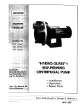
"HYDROoGLASS ''_
ESSU E
I
LE PU
,_E/_/,_,_
__:
___,___,_,i_i!i_ii_i,ii_
i_i_
_ili_i
i!__i_!
!¸I_
_ii
il¸I
!i_
_,_
t.
For
- Installation
® Operation
® Repair Parts
._rence.
Sears, Roebuck and Co., Hoffman Estates, IL 60179
PRINTED
IN U S A
Form NO F642-20g2
U.S.A.
(3/2B/9s)
CONTENTS
nNTRODUCTtON
INTRODUCTION/WARRANTY
.......................................... 2
SAFETY ...............................................................................
2
PREPARATION ................................................................... 3
INSTALLATION ..............................................................
ELECTRICAL......................................................................
Please take a few minutes to read our instructions before
you install and use your pump_ This will help you obtain
the full benefits from this pump It will also help you
avoid any needless service costs that result from causes
we cannot control and cannot cover in our warranty°
4-5
6
OPERATION ........................................................................ 7
MAINTENANCE ...........................................................................
9
TROUBLESHOOTING/PUMP
PERFORMANCE ............. 10
REPAIR PARTS ................................................................... 11
FULL ONE YEAR WARRANTY
ON PUMPS
For one year from the date of purchase, Sears will repair or replace this pump, free of charge, if defective in material or
workmanship.
LIMITED WARRANTY ON SEARSHYDRO-GLASS ®PUMPS
After one year and through two years from the date of purchase, Sears will furnish, free of charge, a replacement part for any
defective part, You pay for labor.
This warranty does not cover repairs or replacement parts necessary because of abuse or negligence including failure to
install, adjust and operate this pump according to the instructions in the owner's manual.
LIMITATION OF WARRANTY
SEARSWILL NOT BE LIABLE FOR LOSS OR DAMAGE TO PROPERTY OR ANY INCIDENTAL OR CONSEQUENTIAL LOSS
OR EXPENSEFROM PROPERTY DAMAGE DUE DIRECTLY OR INDIRECTLY FROM THE USE OF THIS PRODUCT.
Some states do not allow the exclusion or limitation of incidental or consequential damages, so the above limitation or
exclusion may not apply to you.
•WARRANTY SERVICE IS AVAILABLE BY SIMPLY CONTACTING THE NEAREST SEARSSERVICE CENTER/DEPARTMENT IN
THE UNITED STATES: This warranty applies only while the product is in use in the United States....
This warranty gives you specific legal rights, and you may also have other rights which vary from state to state.
Sears, Roebuck and Co., Dept. 817 WA, Hoffman Estates,IL 60179
RULES FOR SAFE [NSTALLATaON AND OPERATION!
Carefully read and follow all safety instructions
manual or on pump.
in this
This is the safety alert symbol. When you see this
symbol on your pump or in this manual, look for one
of the following signal words and be alert to the potential
for personal injuryI
DANGER
warns about hazards that will
cause serious personal injury,
damage if ignored_
[A'WARNING]WARNING
death or major property
warns about hazards that can
cause serious personal injury,
damage if ignored.
death or major' property
[A CAUTION]CAUTION warns about tlazards that will or
can cause minor personal injury or property damage if
ignored°
The word NOTICE indicates special instructions which
are important but not related to hazards_
l_To avoid risk of serious bodily injury and property
damage, read safety instructions carefully before
installing pump_
2. Follow local and/or national plumbing and electrical
codes when installing pump_
3. Keep well covered while installing pump to prevent
leaves and other debris from falling into well,
contaminating well and possibly damaging pump_
4. Protect pump and piping system from freezing.
Allowing
pump or water system to freeze could
severely damage pump and voids warranty_
[_WARNING]Hazardous
Voltage. Can shock, burn,
cause death, or start fires.
5o Disconnect electrical power source before installing or
working on pump.
6. Ground pump with a ground wire run from grounding
lug on motor to a grounded lead in the service panel.
7_ Line voltage and frequency of electrical power supply
must agree with motor nameplate°
8. Use of fuses or wire smaller than size recommended
in owner's manual can cause overheating, possible
fires, and will void warranty_
8. Pump water only with this pump.
9. Do not run pump dry. To do so will damage seals and
can cause leaking and property damage.
Before
You Install Your Pump
BASIC TOOLS
AND
MATERIALS
NEEDED
Pipe Wrenches
Hacksaw
Screwdriver
Check Valve
Adjustable Wrench
Knife
Teflon Tape
NOTICE: Welt must not be more than 20' depth to water.
1. Long runs and many fittings increase friction and
reduce flow. Locate pump as close to well as possible:
use as few elbows and fittings as possible°
2_ Be sure well is clear of sand. Sand will plug the pump
and void the warranty°
3, Protect pump and all piping from freezing_ Freezing
will split pipe, damage pump and void the warranty.
Check locally for frost protection
requirements
(usually pipe must be 12" below frost line and pump
must be insulated).
741 0993
Figure 2 - Foot Valve Must Work Freely
No Sags
4, Be sure all pipes and foot valve are clean and in good
shape.
5_ No air pockets in suction pipe.
6.
No leaks in suction piper Use Teflon tape or PlastoJoint Stik to seal pipe joints,
7. Unions installed near pump and well
servicing. Leave room to use wrenches.
8.
will
aid in
Keep Pipe Straight and Angled up to Pump
[gWARNtNG]Pump body may explode if used as a
booster pump. DO NOT use in a booster application.
Figure 3 - No Air Pockets In Suction
Bedy
PipeJointCompoundWill
.... .,:_:::.
:,,Damage Prastic
Use New Pipe for'B_i'_sui:is
:_
From
Welt
No Air Leaks tn Suction:._!_iiii:ii:_
i iiiiiii!::_..
_:?i_
_:?;:!::
.......... .,::?)Z
;)?
_:"
Figure 1 - No Dirt Or Scale In Suction Pipe
Use Teflon Tape
Figure 4 - Suction Pipe Must Not Leak
Well Pipe Installation
NOTICE: Use the installation
matches your well type°
method
below
which
[_ck
vaive
CASED WELL INSTALLATION
Io Inspect foot valve to be sure it works freely. Inspect
strainer to be sure it is clean°
2o Connect foot valve and strainer to the first length of
suction pipe and lower pipe into well Add sections of
pipe as needed, using Teflon tape on male threads_ Be
sure that all suction pipe is leakproof or' pump will
lose prime and fail to pump. Install foot valve 10 to 20
feet below the lowest level to which water will drop
while pump is operating (pumping water level). Your
well driller can furnish this information.
_
coupling
3. To prevent sand and sediment from entering the
pumping system, the foot valve/strainer should be at
least 5 feet above the bottom of the well
.,__Wel_ point
4_ When the proper depth is reached, install a sanitary
well seal over the pipe and in the well casing. Tighten
the bolts to seal the casing.
5o When using a foot valve, a priming tee and plug as
shown in Figure 5 are recommended
(trlve p_pe
_.,..._Dr'_ven
point
Figure 6 - Driven Point Installation
plug
Priming
Plug
Primingtee
Suction/
pipe
Standingwater
level (pump off)
Draw_ewn water
levet (pump on)
1'(3-sm)
Valve
846 0494
At feast 5 feet (1 5 m)
Figure 7 - Multiple
Figure 5 - Cased/Dug
Well Installation
2.. Install a check valve in horizontal pipe. Flow arrow on
check valve must point toward pump.
HORIZONTAL
DUG
WELL INSTALLATION
Io Same as cased well installation.
DRIVEN
POINT
INSTALLATION
I_ Connect the suction pipe to the drive point as
illustrated in Figure 6o Keep horizontal pipe run as
short as possible, use Teflon tape on male pipe
threads Multiple well points may be necessary to
provide sufficient water to pump_
Discharge
i.
PIPING
FROM WELL TO PUMP
Never install a suction pipe that is smaller than the
suction port of the pump_
2. To aid priming on well point installations, install a line
check valve as shown in Figure 6. Be sure check valve
flow arrow point toward pump.
DISCHARGE
I,
PIPE SIZES
If increasing discharge pipe size, install reducer in
pump discharge porL Do not increase pipe size by
stages°
2. Whenthepumpis setawayfromthepointsof water
use,the dischargepipesizeshouldbe increased to
reduce pressure losses caused by friction,
o Up to 100' run: Same size as pump discharge port.
= 100' to 300' run: Increase one pipe size,
= 300' to 600' run: Increase two pipe sizes.
LAWN SPRINKLING
APPLICATION
This pump is designed for lawn sprinkling° It is designed
to deliver plenty of water at full sprinkler pressure It can
pump from a pond, cistern or well points
Pump discharge can be divided to supply two (2) or more
sprinkler systems• A suggested multiple discharge to
service is shown in Figure 7, Page 4_
Do not use in a pressure tank or booster pump application.
Pump/Piping
PUMP
Figure 9- Independently Support All Piping
Attached To Pump
Pipe Joint Compound Will
.........Damage Plastic
installation
No Air Leaks in Suction P}_
INSTALLATION
NOTICE: Use Teflon tape supplied with the pump for
making all threaded connections to the pump itself Do
not use pipe joint compounds on the pump: they can
react with the plastic in the pump components.
!:,
",,Air Fto;s "
1, Bolt pump to solid, level foundation
::::::::::::::::::::::::::::::::::::
• :::::::::::::::::::::::
2. Support all piping connected to the pump,
3. Wrap t-1/2 to two layers of Teflon tape clockwise (as
you face end of pipe) on all male threads being
attached to pump.
4o Tighten joints
overtighten.
hand tight plus 1-1/2 turns° Do not
NOTICE: Install pump as close to well head as possible.
Long piping runs and many fittings create friction and
reduce flow.
NOTICE: For long horizontal pipe runs, install a priming
tee between check valve and well head as shown in
Figure 5, Page 4, For driven point installations, install a
check valve as shown in Figure 6, Page 4. Be sure check
valve flow arrow points toward pump
Use Teflon Tape
Figure ! 0 - Use Teflon Tape Or Plasto-Joint Stik on
Pipe Joints and Connections to Pump
Use schedule 80 or iron pipe, See "Well Pipe Installation"
for more information_
From
Well
ill,
r/ ooo"
Hand Tight Plus 1-112 Turns With Wrench
748 0993
Figure 8 - Bolt Pump Down
Figure 11 - Don't Overtighten
Electrical
Risk of serious or fatal
electrical shock.
I_WARNINGI Disconnect power at service panel before
connecting pressure switch.
Connect motor ground wire
before connecting power
supply wires.
To convertdual-voltagemotors
from 230 to 115 Volts:
Do not ground to a gas
supply line.
tracerfrom B toA
Moveblackwire
fromA toLI_
NOTICE; 2 HP motors
are 230 Voltonly;
do notconnect
to 115 voltpower;
/
/
Turn off power before
working on pump or motor.
MotorGround
_._. _ Screw t
_
Wire
"
White w/
Ground
;:i u
Connect ground wire
to motor ground screw
as shown,,
Connect power supply wires
to the terminal beard
as shown_
Black /
Clamp
power
cable
to prevent
strain on
terminal
screws
wiring
Dual voltage motors come factory wired
operation. Inset shows 115 Volt conversion.
Use wire size specified in wiring chart. If possible,
connect pump to a separate branch circuit with no other
appliances on it.
lvlnstalt,
ground, wire and maintain
pump in
accordance with your local electrical code and aJl
other codes/ordinances that apply° Consult your local
building inspector for code information°
2o Connect ground wire first as shown at lefto Ground wire
must be a solid copper wire at least as large as power
supply wires°
• Connect ground wire to grounded lead in service
panel, metal underground water pipe, well casing at
least 10' (3M) long, or to ground e_ectrode provided
by power' company.
E82 0494
FIGURE 12 - 115/230
volt motor
through typical pressure switch.
Match motor voltage and power supply voltage° Supply
voltage must be within ±10% of motor nameplate voltage_
Incorrect voltage can cause fire or seriously damage motor
and voids warranty, If in doubt, consult a licensed
electrician°
connections
3. Connect power supply wires as shown at left,
for 230 volt
Do not alter wiring in single voltage motors.
Match motor voltage to power supply voltage.
WIRING CHART
Recommended Wire and Fuse Sizes
DISTANCE IN FEETFROM MOTOR TO METER
L
Branch
Fuse*
0'
51'
TO
50'
TO
100'
Pump
Model
HP
Volt
Max.
Load
Amps
390.262451
1
1t5
230
t4_8
7.4
20
15
12
14
12
14
12
14
390.262551
1-!/2
1t5
230
19.2
9.6
30
15
10
t4
10
14
390.262651
2
230
12.0
15
14
14
Rating*
Amps
Min.
Wire
101'
TO
200'
201'
TO
300'
301'
TO
400'
401'
TO
500'
WIRE SIZE
Size
*Dual element or Fusetron time delay fuses recommended for all motor circuits,
10
14
8
!4
8
14
6
12
6
12
14
12
.....! 2
6
[
12 [
4
1.0
4
10
2
lO
lo
8
Operation
PRIMING
more than 20') and length of horizontal run (10' of
horizontal suction pipe = 1' of vertical lift due to
friction losses in the pipe)°
THE PUMP
NOTICE: 'Priming' refers to the pump expelling all air in
the system and beginning to move water from its source
out into the system. It does not refer only to pouring water
into the pump (although pouring water in is usually the
first step),
if no water is produced within ! 0 minutes, stop pump,
release all pressure, remove priming plug, refill and try
again..
_
NOTICE: NEVER run pump dry. Running pump without
water in it will damage seals and can melt impeller and
diffuser° To prevent damage, fill pump with water before
starting.
I_ Remove priming plug (Figure 13)o
2, Make sure suction and discharge valves and any hoses
on discharge side of pump are open,
3o Fill pump and suction pipe with water,
4_ Replace priming plug, using Teflon tape on thread;
tighten plug,
NOTICE:
If a priming
tee and plug have been
provided for a long horizontal
run, be sure to fill
suction pipe through this tee and replace ptugo (Don't
forget to Teflon tape the plug_)
5o Start pump: water should be produced in 10 minutes
or less, the time depending on depth to water (not
b
IAWARNING..}Hazardous pressure and risk of explosion
and-_-scaidingoIf pump is run continuously at no flow (that
is, with discharge shut off or without priming), water
may boil in pump and piping system. Under steam
pressure, pipes may rupture, blow off of fittings or blow
out of pump ports and scald anyone near.
To prevent explosion, do the following:
Ao Be sure discharge (valve, pistol grip hose nozzle, etc.)
is open whenever pump is running.
B.. If pump fails to produce water when attempting to
prime, release all pressure, drain pump and refill with
cold water after every two attempts.
C. When priming, monitor pump and piping temperature°
if pump or piping begin to feel warm to the touch,
shut off pump and allow system to cool off. Release all
pressure in system and refill pump and piping with
cold water.
Minutes
,
Figure 15 - Run Ten Minutes Or Less
i:: ¸
Figure 13 - Remove Priming Plug
t
Figure 14 - Fill Pump Before Starting
Figure 16 -Do Not Run Pump With
Discharge Shut Off
•
Maintenance
Pump and piping need not be disconnected to repair or
replace motor or seal (see Figure 18)_ If motor is replaced,
replace the shaft seal (Key Nov 6, Page 1 I). Keep one on
hand for future use.
Be sure to prime pump before starting_
NOTICE: Check motor label for lubrication instructions.
The mechanical shaft seal in the pump is water lubricated
and self-adjustingo
NOTICE: Drain pump when disconnecting
or when it might freeze,
PUMP
from service
DISASSEMBLY
Io Disconnect power to motor
NOTICE: Mark wires for correct assembly_
2, Remove clamp (see Figure 18).
3o Remove pump base mounting bolts° Motor assembly
and back half of pump can now be pulled away from
pump front half (Figure 18). CAREFULLY remove ORing_
CLEANING/REPLACING
IMPELLER
NOTICE: First, follow instructions under "Pump Disassembly",
I_ Remove four screws fastening diffuser to seal plate;
remove diffuser (see Figure 19), Exposed impeller can
now be cleaned_
2, If impeller must be replaced, loosen two machine
screws and remove motor canopy (see Figure 20)°
_
•
3o [ _,WARNING ]Capacitor
voltage may be hazardous. To
discharge capacitor, hold insulated handle screwdriver BY THE HANDLE and short capacitor terminals
together
(see Figure 20)o Do not touch metal
screwdriver blade or' capacitor terminals, If in doubt_
consult a qualified electrician,
4, Unscrew capacitor clamp and remove capacitor, Do
not disconnect capacitor wires to motor',
5_ Slide 7/16" open end wrench in behind spring loaded
switch on motor end of shaft; hold motor shaft with
wrench on shaft flats and unscrew impeller by turning
counterclockwise when looking into eye of impeller.
6v To reinstall, reverse steps 1 through 5.
7o See directions under "Pump Reassembly," Page 9
REMOVING
OLD SEAL
1o Follow instructions under "Pump Disassembly".
2, Follow steps 2 through 5 under "Cleaning/Replacing
Impeller
3, Unscrew four nuts holding pump back half to motor.
Remove rotating
half of seal by placing
two
screwdrivers
under back half of pump body and
carefully prying up (Figure 21). Back half of pump
body will slide off shaft, bringing seal with it.
NOTICE: Be sure you do not scratch or mat shaft; if shaft
is marred, it must be dressed smooth with fine eme W or
crocus cloth before installing flew seal. DO NOT reduce
shaft diameter[
4. Place pump body half face down on flat surface and
tap out stationary half of seal (see Figure 22),
INSTALLING
NEW SEAL
I.
Wet outer edge of Rubber Cup on ceramic seat with
liquid soap. Be sparing!
2, Put clean cardboard washer on seal face. With thumb
pressure, press ceramic seal half firmly and squarely
into seal cavity in seal plate (see Figure 23). Polished
face of ceramic seat is up, If seal will not seat
correctly, remove_ placing seal face up on bench,
Reclean cavity Seal should now seat correctly.
3, If seal does not seat correctly after recleaning cavity,
place cardboard washer over polished seal face and
carefully press into place using a piece of standard
'3/4" pipe as a press°
%=
IM_ 04_4
Figure 19- Remove Diffuser
Figure 17 - Disconnect
Power
_WARNING
To avoid e|ectrical
shockhazard,use
insulated-handle
screwdriverto short
capacitor terminals
as shown,
Figure 18 -Slide
Motor
Back
Figure 20 - Hold Shaft
Maintenance
(Continued)
NOTICE: Be sure you do not scratch seal face°
4, Dispose of cardboard washer and recheck seal face to
be sure it is free of dirt, foreign particles, scratches and
grease,
5, Inspect shaft to be sure it is free of nicks and
scratches,
6, Reassemble pump body half to motor flange. BE SURE
it is right side up.
7. Apply liquid soap sparingly (one drop is sufficient) to
inside diameter of rotating seal member.
8, Slide rotating seal member (carbon face first) onto
shaft until rubber drive ring hits shaft shoulder,.
NOTICE: Be sure not to nick or scratch carbon face of
seal when passing it over threaded shaft end or shaft
shoulder° The carbon surface must remain clean or short
seal life will result.
9. Hold motor shaft with 7/I 6" open end wrench on
shaft flats and screw impeller onto shaft. Be sure you
do not touch capacitor terminals with body or any
metal object. Tightening impeller will automatically
locate seal in correct position,
I OoRemount diffuser on pump body half with five screws.
Be CarefulThat
Does not Damage
Seal Face
Shaft Shoulder
/
Ceramic Face
Carbon Face
_oT_osm
Figure 24 - Protect Seal Faces
PUMP
REASSEMBLY
1, Clean O-Ring and O-Ring groove.
2. Put O-Ring in groove on face of flange; put pump
halves together (see Figure 25).
3, BE SURE inside of clamp is clean. Place clamp on
pump halves; snug up. Alternately tighten screw and
tap clamp with mallet to seat O-Ring (see Figure 26),
4, Replace base mounting bolts,
5_ Replace motor wiring; close draincocko
6. Prime pump according to instructions, See "Operation,"
70 Check for leaks.
Figure 21- Remove Seal plate
Figure 25 - Assemble Pump
Figure 22 - Tap Out Seal
Figure 26 - Tap Clamp While Tightening
Figure 23 - Press in New Seal
Troubleshooting
SYMPTOM
Motor
CORRECTIVE ACTION
POSSIBLE CAUSE(S)
will not run
Chart
1.
Disconnect
I
Be sure switch is on
2,
Fuse is blown
switch is off
2
Replace fuse
3,
Starting switch is defective
3, Replace starting switch
4.
Wires at motor are loose,
disconnected, or wired incorrectly
4
Refer to instructions on wiring
Check and tighten all wiring.
[ _WARNiNG
[Capacitor voltage may be hazardous, To discharge
capacitor, hold insulated handle screwdriver BY THE HANDLE and
short capacitor terminals together. Do not touch metal screwdriver
blade or capacitor terminals, if in doubt, consult a qualified
electriclano
Motor runs hot and
1,
Motor is wired incorrectly
1. Refer to instructions
overload
kicks off
Z
Voltage is too low
2
Motor runs but no
water is delivered
"1.
Pump in new installation did
not pick up prime through:
a. Improper priming
b. Air leaks
1, In new installation:
c
Pump has lost prime through:
a Air leaks
b Water level below suction
i'2
looking for other
causes Unscrew
if wire
a, Re-prime according to instructions
b Check all connections on suction line
c. Leaking foot valve
*(Note: Check
prime before
on wiring
Check with power company, Install heavier wiring
size is too small (See Electrical, Page 6)
2.
Replace foot valve
In installation already in use:
a. Check all connections on suction line and shaft seal
b
of pump
Lower suction line into water and re-prime If receding water level
in welt exceeds suction lift, a deep wel! pump is needed
priming plug and
see if there is water
3.
impeller
in priming hole)
4
Check valve or foot valve is stuck
in closed position
4
5
6
Pipes are frozen
Foot vatve and/or strainer are
5, Thaw pipes. Bury pipes below frost line, Heat pit or pump house
6, Raise foot valve and/or strainer above wel! bottom
is plugged
3. CIean impeller; see Maintenance
Rep]ace check valve or foot valve
bu!!ed in sand or mu d
Pump does
deiiver
waternot
to full
1
Water
level in well is Iower than
estimated
capacity (Also
check point 3
2
Steel piping (if used) is corroded
llmed, causing excess friction
immediately
above _, 3.
Offset piping
1
or
A deep well jet pump may be needed (over 20 ft to water)
2. Replace with plastic pipe where possible, otherwise
is too small in size
with new steel pipe
3. Use larger offset piping
TABLE II
PERFORMANCE CHART (IN GALLONS PER MINUTE)
390.262451
1 H.P.
DISCHARGE
PRESSURE
390.262551
1-t/2 H,P.
20'
45
44
390.262651
2 H_P.
DISTANCE ABOVE TO WATER
5'
10'
15'
20'
67
6]
56
46
66
58
55
45
PS!
5'
10'
15'
10
55
49
48
15
51
46
45
20
4s
42 "
30
38
31
35
28
32
24
29
20
55
48
52
45
35
23
19
]6
11
39
37
34
28
42
38
35
32
40
45
t7
13
8
33
27
20
11
34
30
27
23
18
14
8
13
10
37 I
-
50
-
I
so I
m
.
5'
10'
15'
20'
69
67
65
62
65
63
60
58
So
s4
1 44 " so
51
44
.
.
43
37
-
.
.
52
47
25
14
m
.
.
50
45
18
.
.
7
u
DISCHARGE
PIPE
1-1/2"
NPT
I-1/2"
NPT
2" NPT
1-1/2"
NPT
1-1/2"
NPT
2" NPT
TAPPING
SUCTION
PIPE
TAPPING
]o
48
42
s2
_
45
40
SEARS "HYDRO-GLASS
MODELS
390.262451,
"® SPRUNKLER PUMPS
390.262551
and 390.262651
4A
lg
15
3
/
4
5
6
t6
18
12
9
10
11
13
Toorder parts, call:
SearsProductService,1-800-366-7278
Part
Description
Key
No.
1
2
3
4
4A
4B
5
6
7
e
8
8A
9
tlA
t2
13
14
15
16
17
t8
19
20
2t
i
J218-955C
C69-2
WC78-39T
L176-47P1
Motor
Slinger
Priming Plug I/2" NPT
Tank Body Back Half Complete
Tank Body Back Hail
Seat Plate Insert
U9-399
Impeller
impeller Screw
Diffuser
Diffuser
Screw - #8 - 32 RH
Req'd; 2 HP -2
"V _'Clamp
Tank Body Front Half(End No 12)
Tank Body Front Half Complete (tnd
Drain Plug - t/4 NPT
O-Ring
Base
Flat Washer 5/16 (2 Req'd )
Nut - 5/16 - 18 (4 Req'd }
Rubber Pad
Lock Washer - 5/16 (2 Req'd )
Capscrew (2 Req'd )
Flat Washer 5/t6 (2 Req'd )
Capscrew (2 Req'd )
Owner's Manual
- Not illustrated
390,262551
115/230V
60 Cy/1 Ph
lq12 HP
J218-956C
C69-2
WC78-39T
L176-47Pt
390.262651
230V
60 Cy!1 Ph
2 HP
J218-957C
C69-2
WC78-39T
C!03-189P
O-Ring
Shaft Seal for 5/8" Shaft
(1 and 1-1/2 HP-4
10
1t
390.262451
115/230V
60 Cy/1 Ph
1 HP
2784
C105-92PVB
U9-399
2784
C105-92PBBB
CI-258PCA
C1_258PCA
U30-869SS
U30-869S5
C19-5455
C176-53P
C19-54SS
C176-53P
WC78-40T
U9-226
C4.42P
U43-61ZP
U36-37ZP
C35-11
U43-tlZP
WC78-40T
U9-226
C4-42P
U43-61ZP
U36-37ZP
C35-11
U43-11ZP
J3-2
Ug-228A
2784
C105-214PFA
C30-51SS
C1-274P
U30-542SS
Req'd )
Nos 3 and 12)
F642-2092
F642-2092
C19-37A
C176-62P
WC78-40T
U9-393
C4-42P
C35-1t
U30-7755
U43-42SS
U30-74SS
F642-2092
"HYDRO-GLASS ''®
G P
U
SPRI KLE
U
Now that you have purchased
your Sprinkler
Pump,
should a need ever exist for repair parts or service,
simply contact any Sears Service Center. Be sure to
provide all pertinent facts when you call or visit.
The Model Number of your Sprinkler Pump will be
found on a plate attached to the side of the pump body,
WHEN ORDERING REPAIR PARTS, ALWAYS GIVE
THE FOLLOWING INFORMATION:
• PART NUMBER
• PART DESCRIPTION
- MODEL
o NAME OF ITEM
NUMBER
All parts listed may be ordered
Center.
from any Sears Service
If the parts you need are not stocked locally, your order
will be electronically transmitted to a Sears Repair Parts
Distribution Center for handling_
When Sears arranges the installation, you can be sure
the job is done right. We will arrange for professional
workmanship...and
we'll take care of the entire project.
What's more, during installation
you get insured protection...against
property
damage
and also against
accidents to workmen. All you have to do is talk to your
Sears salesperson
or call your nearest store today for
detailed information.
Sears, Roebuck and Co., Hoffman Estates, IL 60179
U.S.A.