1
OPERATOR'S
MANUAL
4
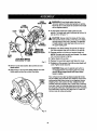
10 in. COMPOUND
MITER SAW
Model No.
315.241940
WARNING: To reduce the risk of
iniury, the user must read and understand the operator's manuat before
using this product,
Customer Hetp Line: 1-800-932-3188
Sears, Roebuck and Co., Hoffman Estates, IL 60179 USA
Visit the Craftsman web page: www.sears.com/craftsman
983000-437
3-04
Save this manual for future reference
• Warranty and introduction.................................................................................................................................................
2
• General Safety Rules.....................................................................................................................................................
3-4
• Specific Safety Rules.....................................................................................................................................................
4-5
• Symbols.........................................................................................................................................................................
6-7
• Electrical............................................................................................................................................................................
8
• Glossary ofTerms..............................................................................................................................................................
g
• Features.....................................................................................................................................................................
10-12
• Tools Needed .................................................................................................................................................................
12
•
13
Loose Parts ....................................................................................................................................................................
• Assembly...................................................................................................................................................................
13-20
• Operation...................................................................................................................................................................
20-26
• Adjustments..............................................................................................................................................................
27-28
•
Maintenance...................................................................................................................................................................
29
•
Parts Ordering/Service...................................................................................................................................................
30
ONE YEAR FULL WARRANTY
ON COMPANION TOOL
If this Companiontool fails due to a defect in material or workmanshipwithin one year from the date of purchase,
RETURN IT TO THE NEARF__TSEARS STORE IN THE UNITED ffrATE8, and Sears will replace it, free of charge.
This warranty is void if this tool is used for commercial or rental purposes.
This warranty gives you specific legal rights,and you may also have other rights which vary from state to state.
Sears, Roebuck and Co., Dept. 8t7 WA, Hoffmen Eatates, IL 60179
This tool has many features for making its use more pteas_nt and enjoyable. Safety, performance,end dependability
have been given top pr)oriL'yin the design of this product making )t easy to maintain and operate.
2
,_
• SECURE WORK. Use clamps or a vise to hold work
when practical. It's saferthan usingyour hand and
|rees both hands to operate tool
WARNING: Read and understand all inatrucl
tlone. Failureto follow all inst_'uctionslisted below,
may rssuttin etecLricshock, fire and/or serious
persona_iniury.
•
DON'T OVERREACH. Keep proper footingand bah
ance at all times.
•
MAINTAIN TOOLS WITH CARE. Keep toolssharp and
clean for better and safer performance. Follow instructionsfor lubricating and changingaccessories.
•
DISCONNECT TOOLS. When not in use, before servicing,or when changing attachments,blades, bits,
cutters, etc., all tools shouldbe disconnected.
AVOID ACCIDENTAL STARTING. Be sure switch is off
when pluggingin anytool.
USE RECOMMENDED ACCESSORIES. The use of
improper accessories may risk injury.
READ ALL iNSTRUCTIONS
•
•
•
•
•
•
•
•
KNOW YOUR POWER TOOL. Read the operator's
manual carefully.Learnthe eawls applicationsand limitations as well as the specific potential hazardsrelated
to this tool.
GUARD AGAINST ELECTRICAL SHOCK BY PREVENTING BODY CONTACT WITH GROUNDED
SURFACES. For examp]e, pipes, radiators, ranges,
refrigeratorenclosures.
KEEP GUARDS IN PLACE and In good working order.
REMOVE ADJUSTING KEYS AND WRENCHES.
Form habit of checking to see that keys and adjusting
wrenches are removed frpm tool before turning it on.
KEEP WORK AREA CLEAN. Cluttered areas and
benchesinvite _ccidenta.
00 NOT _aavetoolsor
pisces of wood on the saw whila It is in operation.
DO NOT USE IN DANGEROUS ENVIRONMENTS.
Do not usa power tools in damp or wet focations or
expose to rain. Keep the work areawell tit.
KEEP CHILDREN AND VISITORS AWAY. All visitors
shouldwear safety glassesand be kept a safe dLslance from work area. Do not let visitorscontact tool or
extensioncord white operating.
•
•
• NEVER STAND ON TOOL, Serious injury could occur
if the tool istipped or if the cutting tool is unintentionally contacted.
• CHECK DAMAREO PARTS. _fore further LLSe
Of
the tOO[,a guard or other pert that is dsmeged should
be carefullychecked to determine that it willoperate
properlyand perform its intended function.Check for
alignment of moving pe_Ls,binding of moving parts,
breakage of parts, mounting and any ot_er conditions
that may aff'ecf:its operation.A guard or other part that
is damaged must be properlyrepaired or replaced by
an authorized service center toavoid risk of personal
injury.
• USE THE RIGHT DIRECTION OF FEED. Feed work
into a blade or cutter againstthe direction of rotation of
blade or cutter only.
• NEVER LEAVE TOOL RUNNING UNATrENDED,
TURN THE POWER OFR Don't leave tool until it
comes to a complete stop.
II PROTECT YOUR LUNGS. Wear a face or dust mask if
the cutting operation is dusty.
MAKEWORKSHOPCHILDPROOFwith
padlock.sand
master switches, or by removingsLarterkeys.
•
DON'T FORCE TOOL. [t will do the job better and
eater at the feed rate for which it was designed.
• USE RIGHT TOOL. Don't force the tool or attachment
to do aiob it was not designed for. Don't use Rfor a
purpose not intended.
• USE THE PROPER EXTENSION CORD. Make sure
your extension cord is in good condition. Use only a
cord heavy enoughto carry the current your product
will draw. An undersizedcord will cause a drop In line
voltage resultingin loss of power and overheating.A
wire gauge size (A.W.G.)of at least 14 is recommended
for an extensioncord 25 feet or less in length. If in
doubt, use the next heavier gauge. The smallerthe
gauge number,the heavierthe cord.
•
PROTECT YOUR HEARING. Wear hearingprotection
duringsxtandsd periodsof operation.
• DO NOT ABUSE CORD. Never yank cord to disconnect from receptacle. Keep cord from heat, oil, and
sharp edges.
• USE OUTDOOR EXTENSION CORDS. When 'Lociis
uead outdoors,usa onlyextension cordswith approved ground connection that are intendedfor use
outdoorsand so marked.
• DRESS PROPERLY. Do not wear loose clothing,
gloves, neckties, or jewelry. They can get caught
and draw you into moving parts. Rubber glovesand
nonskid footwear are recommended when working
outdoors.Alsowear protective ha'rrcoveringto contain
long hair.
• ALWAYS WEAR SAFETY GI.ASSEB WITH SIDE
SHIELDS. Everyday eyeglasseshave only impactresistantlenses, they are NOT satety glassas.
•
KEEP BLADES CLEAN, SHARP, AND
WTTH SUFFICIENT SET. Sharp blades minimizestall l
ing and kickback.
• BLADE COASTS AFTER BEING TURNEDOFR
• NEVER USE IN AN EXPLOSNE ATMOSPHERE.
Normal sparkingof the motor could ignite fumes.
3
•
•
•
•
•
•
INSP ECT TOOL CORDS PERIODICALLY. If damaged,
have repaired by a qus_od sarvica t_.hn_lan at _n
authorizedservice fae){ity. The conductor with insulation having an outer surface that is green with or without yellow eVipse isthe equipment-groundingconductor. If repair or replacement of the electric cord or plug
is necessary,do not connect the equipment-grounding
conductorto a[[ve terminal Repair or replace a damaged or worn cord immediately.Stay constantlyaware
of cord location and keep it well away from the rotating
b_da.
INSPECT EXTENSION CORDS PERIODICALLY and
replace if damaged.
KEEP TOOL DRY, CLEAN, AND FREE FROM OIL
AND GREASE. Always use a dean c_othwhen cleaning. Never use brake fluids, gasoline, petroleum-based
products, or any solvents to clean tool
STAY ALERT AND EXERCISE CONTROL, Watch
what you are doing and use common sense. Do not
operate too{when you are tired. Do not rush.
DO NOT USE TOOL IF SWITCH DOES NOT TURN IT
ON AND OFF. Have defective switches replaced by an
authorizedservice center.
USE ONLY CORRECT BLADES. Do not use b{ades
with incorrectsize hoise. Never use blade washers or
b_de bolta that are defective or {nCOTT_"_.
"[hemBx_mum b%adaeapad_ of your saw Is 10 in. (254 ram).
•
FIRMLY CLAMP OR BOLT your miter sew to a workbench or table at approximately hip height.
• KEEP HANDS AWAY FROM CUTrlNG AREA. Do not
reach underneath wor!<or in blade cutting path wlth
your hands and fingersfar any reason. Always turn the
power off.
• ALWAYS SUPPORT LONG WORKIPIECES while cutting to minimizerisk of blade pinchingand kloid0aok.
Saw may slip, walk or slide while cutting long or heavy
boards.
• ALWAYS USE A CLAMP to secure the workplece
when possible.
• BE SURE THE BLADE CLEARS THE WORKPIECE.
Never start the sew with the blade touchingthe
wcrkpiece. Allow motor to come up to full speed
before starting cut.
• MAKE SURE THE MITER TABLE AND SAW ARM
(BEVEL FUNCTION) ARE LOCKED IN POSITION
BEFORE OPERATING YOUR SAW. Lock the miter
table by securelytightening the miter lock levers. Lock
the saw arm (bevel function}by securely tighteningthe
bevel lock knob.
•
BEFORE MAKING ACUT, BE SURE ALL ADJUSTMENTS ARE SECURE.
•
BE SURE BLADE PATH IS FREE OF NAILS. Inspect
for and remove atf na_sfrom lumber before cutting.
•
NEVER TOUCH BLADE or other moving parts during
UaS.
•
NEVER START ATOOLWHEN ANY ROTATING COMPONENT IS IN CONTACT WITH THE WORKP|ECE.
• DO NOT OPERATE A TOOL WHILE UNDER THE
INFLUENCE OF DRUGS, ALCOHOL, OR AI_Y
MEDICATION.
• WHEN SERVICING use only identic_ replacement
parts. Use of any other pads may create a hazard or
cause productdarr_ge.
• CHECKWITH AQUALIFIED ELECTRICIAN or service
personnelJfthe groundinginstructionsare not completely understoodor it in doubt as to whether the toot
LSproperlygrounded.
• USE ONLY RECOMMENDED ACCESSORIES listed
in this manual or addendums. Use of accessories
that are not listed may cause the risk of personal
injury. Instructions for safe use of accessories are
included with the accessory.
• DOUBLE CHECK ALL SETUPS, Make sure blade is
tight and not making contact w)th saw or workpiece
before connecting to power supply,
•
•
NEVER USE A LENGTH STOP ON THE FREE SCRAP
END OF A CLAMPED WORKPIECE. NEVER hold
onto or bind the free scrap end of the workplace in any
operat'_r_. If =_work clamp and length stop are used
together,they must both be installedon the same side
of the sew _abla to preventthe sew from catching the
loose end and kicking up.
NEVER out more than one piece at a time. DO NOT
STACK more than one workpiece on the saw table at a
time.
NEVER PERFORM ANY OPERATION FREEHAND.
Always place the workpJeceto be cut on the miter
table and positionit f'_mlyagainst the fence as e backstop. Always use the fence.
NEVER hand hold a workpieoethat is too small to be
clamped. Keep hands riser of the cutting arcs.
NEVER reach behind, under,or within three inches
of the blade and its cutting path w_h yourhands and
fingers for any reason.
•
•
NEVER reach to pick up a workpiece, a piece of scrap,
or anything e_ss that is in or near the cutting path of the
b_de,
• AVOID AWKWARD OPERATIONS AND HAND POSITIONS where a sudden slip could cause your hand
to move intothe blade. ALWAYS make sure you have
good balance. NEVER operate yourmiter saw on the
floor or in a crouched position.
MAKESURETHEWORKAREAHASAMPLE
LIGHTING to see the work and that no obstructionswit] intertara with saf_ oper-tion BEFORE psrtorr_in(.} any work
using your saw.
• ALWAYS TURN OFF THE SAW before disconnecting
it to avoid accidental startingwhen reconnectingto
power suppty.NEVER leave the saw unattendedwhile
connected to a powersource.
• NEVER stand or haveany part of your body in line wfth
the path of the saw blade.
• ALWAY8 release the power switch and allow the
saw blade to stop rotating beforeraising it out of the
workpiece.
• DO NOT TURN THE MOTOR SWITCH ON AND OFF
RAPIDLY. "l%his
cou(d cause the saw blade to loosen
and could create a hazard. Shouldthis ever occur,
stand cTserand at_owthe saw blade to come to s complete stop. Disconnectyour saw from the power supply
and socurolyretightenthe blade bolt.
• IF ANY PART OF THIS MITER SAW IS MISBING or
should break, band, or fail in anyway, or shouldany
electrical component fail to perform properly,shut off
the power switch, remove the miter saw plug (Tomthe
power sourceand have damaged, missing, or failed
parts replaced before resumingoperation.
• THIS TOOL should have the following markings:
a)
b)
c)
d)
e)
f)
Wear eye protection.
Keep hands out of path of saw blade
Do not operate saw without guards in pJaos.
Do not perform any operation freehand.
Never reach aroundsew b{ade.
Turnoff tool and walt for saw blade to stop before
moving work.pieceor chang(rigsettings.
g) Disconnectpower (or unplug tool as applicab{e)
before changing blade or servicing.
h) No load speed.
• ALWAYS carry the tool only by the carrying handle.
• SAVE THESE INSTRUCTIONS, Refer to them
frequently and use to instruct other usem. If you loan
someonethis tool, loan them thess instructionsalso.
• ALWAYS STAY ALERT] Do not allow familiarity (gained
from frequent use of your saw) to seuse a careless
mistake. ALWAYS REMEMBER that a careless fraction
of a second is sufficientto inflict severe injury.
WARNING: S(xr_ dust created by power sand{ng,sawing, gr(nding, drii{(ng, end other construction_ctNitiea contains chemicals known to cause cancer, birth defects or other reproductiveharm. Some examples of these chemicals are:
•
leadfrom lead-based paints,
•
crystallinesilica from bricksand cement and other masonry products, and
•
arsenic and chromium from chemically-treated {umber.
Yourrisk (Tom these exposures varies, dependingon how often you do this type of work. To reduce your exposure
to these chemicals: work in a well ventilatedarea, and work with approved safety equipment, such as those dust
masks that are specially designedto filter out microscopicparticles.
5
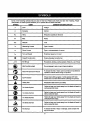
Someof
the followingsymbols may be used on this tool. Please study them and learn their meaning. Proper
interpretation of these symbolswill allow you to operate the tool better and s,_fsr.
SYMBOL
NAME
OESIQNATION/EXPLANATIO N
V
Volts
Voltage
A
Amperes
Current
Hz
Hertz
Frequency(cyclesper second)
W
Watt
Power
Minutes
Time
Aitemeting Current
Type of current
•-
DirectCurrent
Type or a characteristicof current
no
No Load Speed
Rotational speed, at no toad
[]
Class II Construction
Daub[s-insulatedconstruction
Per.Minute
Revolutions,stTokes,surface speed, orbits etc., per minute
Wet ConditionsAJert
Do not expose to rain or use in damp locations.
Read The Operator's Manual
operator's
manual
before
usingthis
product.
To reduce the
risk of
injury,user
must
read and understand
Eye Protection
Atwayswear
gogglesor
safety
glasseswithproduct.
side
shields
and asafety
fullface
shieldwhen
operatingthis
Safety Atert
Precautionsthat involveyour safety.
No Hands Symbo_
serious
Failuretopersonatinjury.
keep your hands away from the blade will rseu_tin
(_
No Hands Symbol
Failureto
keep yourhands away from the blade w_l result_n
serious persona{injury,
e
No Hands Symbol
serious
persona{injury.
Failureto
keep your hands away from the bladewill resultin
No Hands Symbol
Failureto
keep y_ur
hands away from the blade wi{{result in
serious
persona_
in,P/.
Ho'_Surface
To
risk of {niury
ordt_'_age, avoid contact w_th
anyreducethe
hot surface.
rain
..Jmin
(_
6
The following
this product.
SYMBOL
A
signal words and meanings are intended to explain the levels of risk associated
SIGNAL
MEANING
DANGER:
Indica.tssan imrninantlyil_.ardous situation, which, if not avoided, will
result in death or serious fniury.
WARNING:
Indicates a potentially hazardous situation,which, if not avoided, could
resultin death or serious injury,
CAUTION:
Indicates a potentially hazardous situation, which, ifnot avoided, may
result in minor or moderate injury.
CAUTION:
_/ithout Safety Alert Symbol) Indicates a situs,tion that may result in
propertydamage.
SERVICE
Servicingrequiresextreme care and knowledgeand
should be performed only by a qualifiedservice technician. For servicewe suggest you return the productto
your nearestAUTHORIZED SERVICE CENTER for repair.
When servicing, use only identicalreplacement parts.
&
with
WARNING: To avoid serious personalinjury,
do not attempt to use this product untilyou read
thoroughlyand understand comptetalythe
operator'smanual. Save this operators manual
and review frequently for continuingsafe opera
tfon and Ins_'uctingotherswho may usethis
product,
WARNING:
O
The operation of any power tool can resultin foreign objects being thrown into your eyes, which can
result in severe eye damage, Before beginningpower too[ operation,always wear safety goggles
or safety g[aseeswlth side shields and a fullface shield when needed. We reoommendWide Vision
Safety Mask for use over eyeglasses or standard safety glasseswith side shields.Always use eye
protection which is marked to complywith ANSI Z87.1.
SAVE THESE INSTRUCTIONS
EXTENSION
SPEED AND WIRING
CORDS
Use only 3-wire extension cords that have 3-prong
groundingplugs and 3-pole receptaclesthat accept the
tool's plug. When usinga power tool at s considerable
distance from the powersource, use an extension cord
heavy enough to carry the current that the tool will draw.
An undersized extensioncord will causea drop in line
voltage, resultingin a foes of powerand causing the motor
to overheat. Use the chart provided below to determine
the minimumwire size required in an extension cord. Only
round Jacketedcords listed by Underwriter'sLaboratories
(UL) shouldbe used.
The no-load speed of this tool is approximately4,500 rpm.
7his speed is not constant and decreases under a Iced
or with fewer voltage. Forvoltage, the widng in a shop
is as importantas the motor'shorsepower rating.A line
intendedonly for lightscannot properlycarry a power tool
motor. Wire that is heavy enoughfor a short distancewill
be too lightfor a greater distance.A finethat can
support one power tool may not be able to support two
or three tools.
-Ampe_
in the event of a malfunctionor breakdown, grounding
provides _ path of k_astresistancefor electriccurrentto
reduce the risk of electricshock. This tool is equipped
with an electric cord having an equipment-grounding conductor and a groundingplug. The plug must be
plugged intoa matching outletthat is properly installed
and grounded in accordance with all local codes and
ordinances.
GROUNDING
rating (on tool facep!ete)
0-2.0
2.%3,4
Cord Length
3,5-5.0
5.1-7,0
7.%_ 2.0 12,1-'{0,0
Wire Size (A.W.G.)
25'
16
16
16
16
14
14
50'
16
16
_6
_4
14
12
100'
16
16
14
12
10
--
--Ueed on12 gauge - 20 amp circuit
NO'RE:AWG = Amedcan Wire Gauge
Do not modify the plu9 provided. If it win not fit the outlet,
have the proper outlet installedby a qualifiedelectrician.
improper connectionof the equipment-groundingconductor can re,sultina risk of eiectr_ shock. The cond_,tor with insulation hav_ngan outer surface that is green
with or without yellow sffipes is the equipment-grounding
conductor.)f repair or replacementof the electriccord or
plug is necessary,do not connect the equipment-grounding conductor to a live tarmlna}.
When working with the tool outdoors, use an extension
cord that is designed for outside use. This is indicated by
the letters "WA" on the cord's jacket.
Before using an extension cord. inspect it for loose or
exposed wires and cut or worn insulation.
A
INSTRUCTIONS
WARNING: Keep the extension cord clear of the
workrngarea. Positionthe cord so that it wifl not get
caught on lumber,tools or other obstructionswhile
you are workingwith a power tool. Failureto do so
can result fnserious personal injury.
Check with a qualified electrician _r ser_ce persone_el
if
the groundinginstructionsare not completely understood,
or if in doubt as to whether the tool Is properlygrounded.
Repair or replace a damaged or worn cord immediately.
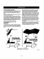
This tool is intendedfor use on a circuitthat hasan outlet
like the one shown in figure 1, It else has s groundingpin
like the one shown.
WARNING: Check extensioncords before each
use. If damaged replace immediately.Never use tool
with a damaged cordsince touching the damaged
are_ cou(d cause s(oc_cat shock resu(tingin serious
Injury.
ELECTRICAL CONNECTION
This tool is powered by a precisionbuilt electric motor.
It should be connected to a power supply that is t20
volts, 60 Nz, AC only (normal household current). Do
not operate this toot on direct current (DC). A substantial
voltage drop wilt cause a loss of power and the motor wltl
overheat, If the saw does not operate when plugged into
an outlet, double check the power supply.
GBDUNDING
PIN
I
COVEROFGROUNDED
OUTLETBOX
Fig. 1
8
Anti-Kickback Pawls (radial arm and table saws)
A dev?sewhich, when property ?nste]ladand maintained,
is designed to stop the workplace from being kioked back
toward the front of the saw during a rippingoperation.
Arbor
The shaft on which a blade or cutting tool is mounted,
Bevel Cut
A cutting operation made with the blade atany angle
otherthan 90" to the table surface.
Non-Through Cuts
Any cutting operation where the blade does not extend
completelythrough the thickness of the workpiecs.
Push Blocks and Push Sticks
Devicesused to feed the work:piecethroughthe saw
blade during cutting operations.A push stick (not a push
block)shouldbe used for narrow rippingoperations.
These aids help keep the operator's hands well away from
the blade.
Chamfer
A cut removinga wedge from • block so the end (or part
of the end) is angled ratherthan at 90 °.
Compound Cut
A cross cut made with both e miter end a bevel angle.
Crosscut
A cutting or shaping operationmade across the grain or
the width of the workpieee.
Cutter Head (Planers and Io/ntera|
A rotating plaoe of adiustablablades. The cutter heed
removes materialfrom the workplece.
Dedo Cut
A non-throughcut which producese squara-sJdsdnotch
or hough in the work,piece (requiresa epsolai blade).
Featherboard
A device used to help centre] the workpJecaby guiding Jt
securelyagainst the table or fence duringany ripping
operation.
FPM or SPM
Feet per minute (or strokes per minute), used in reference
to blade movement.
Pilot Hole (drill presses]
A small hole drilled in a workpiece that serves as a guide
for drillinglarge holes accurately.
Ra_w¢
A cutting operationto reduce the thickness of the workpiece to make thinnerpieces,
Resin
A sticky,eep-based substanoethat hashardened.
Ravoful_tonsPar Minute (RPM)
The number of turnscompleted by a spinning object in
one minute.
Ripping or Rip Cut
A cutting operation along the length of the workplace.
Riving Knife (table saws)
Also known as a spreader or splitter. A metal piece,
slightlythinnerthan the sew blade, which helps keep the
kerr open and also helpsto preventkickback.
_v Blade Path
The area over, under,behind, or in front of the blade. As
it appliesto the wcrkpiece, that areawhich will be or has
been cut by the blade.
Set
The distance that the tip of the saw blade tooth is bent (or
set) outward from the face of the blade.
Freehand
Performinga cut without the workplace being guided by a
fence, miter gauge, or other aids.
Gum
A sticky, esp-bassd residue from wood products,
Heel
Alignmentof the blade to thefence.
Kerr
The material removed by the blade in a through out or the
slot produced by the blade in a non-through or pertlal cut.
Klckback
A hazard that can occur when the blade binds or stalls,
throwingthe workpleoe back towerd operator.
Snips (planers}
DeprassJonmade at either end of s workplace by cutter
bladeswhen the workpiece is not properlysupported.
Throw-Beck
The throwing back of a workpiece usuallycaused by the
wcrkplacs being dropped into the blade or being placed
inadvertentlyin contact with the blade.
Through Sawing
Any cutting operationwhere the blade extends completely
through the thickness of the wcrkpleca.
Work.piece or Material
The item on which the operation is being done.
Worktable
Surface where the workpiece rests while perforatinga
cutting,drilling,planing,or sandingoperation.
Leedlng End
The end of the workpieoe pushed intothe tool first.
Miter Cut
A cutting operation made with the workp?eoeat any angle
to the blade other than 90 °,
g
Product Specifications:
Blade Diameter .........
• ................
Blade Arbor .............................
No Load Speed ......................
10 in.
5/8 in.
4,500/min.
Input .......
120 Volts, 60 Hz, AC Only,12 Amperes
Net Weight .............................
28 Ibs.
When the miter angle (miter t_ble) is set at O"and the bevel
angle is set at 0":
Maximum nomir_l Lumbersizes:
2 x6
When the miter angle (miter ta.ble)isset at 45"and the bevel
angle is set at 0":
Maximum nomir_i lumber sizes:
2x 4
When the miter angle (mitertable) is set at O"and the bevel
ang)e is set at 45":
Maximum nominallumber sizes:
2 x6
When the miter angle (mitertable) is set at 45"and the bevel
angle is set at 45":
Maximum nominallumber sizes:
2 x 4.
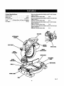
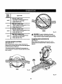
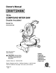
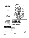
SAWARM
UPPERBLADE
GUARD
DUETGUIDE
BEVELB_LE
LOWER
BEVEL
LOCKKNOB
MITER TABLE
MITER
LOCKLEVER
WORKCLAMP
Fig. 2
10
KNOWYOUR COMPOUNDMITERSAW
SPINDLE LOCK
See Figure 4.
See Figure2.
Before attempting to use this product, familiarize yourself with elf operating features and safety requfrements.
t2 AMP MOTOR
Your saw has a powerful 12 amp motor with sufficient
power to handle tough cuttingjobs. It is made with all
bah bearings,and has externallyaccessible brushes for
ease of servicing.
BUTTON
A spindle lock button has been providedfor lockingthe
spindle which keeps the blade in your saw from rotating.
Depress and hold the lock button while Installing, changing,
or removingblade.
SWITCH
TRIGGER
10 in. BLADE
A 10 in.saw blade is included with your compound
miter saw. )t will cut materialsup to 2 in. thick or 6 in.
wide, depending upon the angleat which the out is being made.
8PINOLE
LOCKBU1]'ON
MITER LOCK LEVERS
See Figure 3.
The miter lock levers securelylock the saw table at the
desired miter angles.
MITERLOCK
LEVERS
Fig. 4
TRIGGER LOCK
See FTgum5.
To preventunauthorizeduseof your oompound miter saw,
we suggest that you disconnect it from the power supply
and lock the switch in the off position.To lock the switch,
install a padlock (not included)through the hole in the switch
trigger.A lookwith e long shackle up to 9/32 in. diameter
may be used. When the lock is installedand locked, the
switch is inoperable.Store the padlock key in another location.
SWITCH
TRIGGER
PADLOCK
Fig. 3
Fig. 5
11
WARNING:Theoperation
ofany saw can result
in foreign objects being thrown into your eyes,
which can result in severe eye damage. Before
stating power tool operation, always wear safety
goggles or safety giaeses with side shieidsand
a full face shield when needed. We recommend
wide vision safety mask for use over eyeglasses or
standard safety glasses with side shields.
BEVEL LOCK KNOB
The bevel lock knob securelylocks yourcompound
miter saw at desired bevel angles. A positive stop adjustment screw has been provided on each side of the
saw arm. These adiustment screws are for making fine
adjustmentsat 0"and 45".
ELECTRIC
BRAKE
An electricbrake has been provided to quicklystop blade
rotationafter the switch isrsreased.
FENCE
The fence on yourcompound miter saw has been provided
as a support to hold your workplace securely againstwhen
making all cuts.
SELF-RETRACTING
LOWER BLADE GUARD
The lower blade guard is made of shock-resistant, seethrough plasticthat providesprotectionfrom each side of
the blade. It feb'actsover the upper blade guard as the saw
is lowered intothe workpiece.
The followingtools (not Included) are needed for checking adjustments of your saw or for ir_talling the blade:
COMBINATION
WRENCH
(2)
10 mm,14mm
COMBINATION
SQUARE
FRAMINGSQUARE
Fig. 6
PHILLIPSSCREWDRIVER
12
Thefollowing
itemsareincluded
withyourCompound
MiterSaw:
•
Saw Blade - 10 ln,
• Blade Wrench
• Work C_amp
• Operator's Manual
=,= _
BLADEWRENCH
WnRKCLAMP
SAWBLADE
Fig. 7
,I_ WARNING: The use of atfachments or accessoriesnot listed might be hazardous and could cause ssdous
personalinjury.
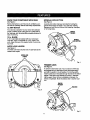
UNPACKING
•
Do not discardthe packing material until you have
carefullyinspected and satlsfactodiyoperated tha tool
• The _w is factory set for accurate cutting.After
assemblingit, checkfor accuracy, ff shippinghas
inSusncedthe settings, refer to spsciflcprocedures
explained in this manual
This product has been shipped completely assambled.
• Carefully lift saw from the carton by the carryinghandle
and the saw base, and place it on a level work surface,
NOT _" This saw is heavy.To avoid back iniury,liftwith
your legs, not your back, and get help when needed.
• Yoursaw has been shipped with the saw arm secured
in t_s down position.To release the saw arm, push
down on the top of the saw arm, cut the tie-wrap, and
pull out on the lock pin.
•
Ifanypartsaredamaged or missing, please call
1-800-932-3188 for assistance.
J_l WARNING= If any partsare missing,do not operate
this toot until the missing parts are replaced. Failure
to do so could result in possibleserious personal
inlury.
• Lift the saw arm by the handle. Hand pressureshould
remain on the saw arm to prevent sudden rise upon
rslsasa of L_etie wrap.
• Inspect the tool carefuffyto make sure no breakage or
damage occurred duringshipping.
13
Your compound miter saw should be permanentlymounted to a firm supportingsurface such as a workbench.
Four bolt holeshave been provided in the saw base for
this purpose. Each of the four mountingholesshould be
bolted securely using3/8 in. machine bolts, lock washers,
and he)( nuts (not inctuded). Bolts shouldbe of sufficient
length to acconvnodate the saw base, lock washers, hex
nuts, and the thickness of the workbench.
d_lb WARNII_I" Do not attempt to modify this tool or
createaccessories not recommended for usewith
this tool. Any such aitaratlon or modifl_,tion is
misuse and could result in a hazardous condition
leading to possibleserious personalinjury.
_k
WARNINGs Do not connect to power supply until
assembly is complete. Failureto comply could
result in accidental startingand possible serious
personal injury.
MOUNTING
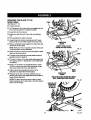
See Figure 8.
Tightenall four bolts securely.
The hoJepe_ern for mountingto a workbenchis shown in
figure 8. Carefullycheck the workbench after mountingto
make sure that no movement can occur during use. If any
tipping, eliding,or walking is notad, secure the workbench
to the floor before operating.
HOLES
WARNING: Ahe_ysmake sum your compound
miter saw fs securelymounted to a workbench or an
approved wcrkstand. Failureto do so could result
in an accident resultingin poSSibleseriouspersonal
injury.
TRACEHOLES
AT THESELOCATIONS
FOR
HOLEPATTERN
TRACEHOLES
ATTHESELOCATIONS
FOR
HOLEPATTERN
NmUNTINGSURFACE
BASE
Fig. 8
14
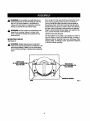
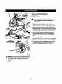
WORK CLAMP
TO INSTALL BLADE
See Figures 10- 12.
See Figure 9.
The work clamp provides greater control by clamping the
workpisce to the fence orthe saw table. It also preventsthe
workpisosfrom creepingtoward the saw blade. This Lsvary
helpfulwhen cutting compound miters,
Depending on the cutting operatlon and the size of the
workplace, it may be necessary to use a C-clamp instead
of the work clamp to secure the workpisca priorto making
the cut.
_k
WARNING: In some operations,the work clamp
assembly may interferewith the operation of the
blade guard assembly.Always make sure thata is
no interferanoewith the blade guard priorto beginning any cutting operation to reducethe risk of
sedous personal injury.
Followthese directionsto installthe work clamp:
•
•
A
Place the shaft of the work clamp in either hole on the
saw table bess.
Rotate the knob on the work clamp to move it in or out
as needed.
WARNING: When using any clamp with a stop
block, install the clamp on the same side as the stop
block, This will eliminatethe possibilityof trapping
the workpiece, resultingin the saw blade and
workplace kickingup. Failureto heed this warning
can resultin esrtous personalInjury.
_L WARNING: A 10 in. blade is the maximum blade
capaoi_ of your saw, Never use a blade that is too
thickto allow outerblade washer to engage with
the fiats on the spindle. Larger bladeswi([come in
contact with the blade guards,while thicker blades
wilt preventthe blade screw from securing the blade
on the spindle, Eitherof these situationscould result
in a serious accident and can cause serious personal
injury.
• Unplug your saw.
_k
WARNING: Failureto unplugyour saw could result
in accidental starting causing possibleserious
personalInlury.
•
Loosen phillipsscrew (A) on the blade bolt cover.
•
Remove phillipsscrew (B) on the blade bolt cover until
blade bolt cover can be raised.
•
Gently raisethe lower blade guard bracket, releasing
lower blade guard fi'omnotch so that lower blade
guard and blade bolt cover can be rotated up and back
to expose the blade bolt.
•
Depress the spindle lock button and rotate the blade
bolt until the spindle locks.
II Using the blade wrench provided,loosen and remove
the blade bolt.
NOTE: The blade bolt has left hand threads. Turn blade
bolt clockwiseto loosen.
WORK
CLAMP
BASE
Fig. 9
SCREW(,A)
LOWERBLADE
GUARDBRACKET
Fig. 10
15
LOWER
BLADEGUARD
WARNING: If inner blade washer has been
removed, replace it before placingblade on spindle.
F_lure to do so could cause an accident since blade
will not tighten properly.
BI.AOE
BOLTCOVER
BLAOE
\
PHILLIPS
SCREW
TO
LOOSEN
•
Fit saw blade inside lower blade guard and onto
spindle. The bladeteeth point downward at the front of
saw as shown in figure 11.
A
CAUTION: Always installthe blade with the blade
teeth and the arrow printed on the side of the blade
pointing down at the front of the saw. The direction
of blade rotation Is also stamped with an arrow on
the upper blade guard,
FLAT(S)
TIGHTEN
INNERBLADE
WASHERWITH
DOUBLE"17'FLATS
•
Replace outer blade washer.The double "D"flats on
the blade washers align with the fiats on the spindle,
I
Depressspindle lock button and replace blade bolt.
NOTE: The blade bolt has left hand threads. Turn blade
bo{tcountsrc(ockwiseto tighten.
•
Tightenblade bolt securely.
BLADE
BOLT
OUTERBLADEWASHER
W_H DOUBLE"D'FLATS
• Replace the lower blade guard and blade bolt cover.
II Retightsn phillipsscrews (A and B) secudng blade bolt
cover.Tighten straw securely.
Fig. 11
•
Remove outer blade washer. Do not remove inner
blade washer.
CAUTION: Make sure the spindle lock button is
not engaged before reconnectingsaw into power
source. Never engagespindle Jookbutton when
blade is rotating.
• Wipe a drop of oil onto Inner blade washer and outer
blade washer where they contact the blade.
Your compound miter saw has been adjusted at the factory for making very accurate cuts. However,some of the
componentsmight have moved out of alignment during
shipplng.Also, over a period of time, read]ustmenL will
probabtybecome necessary due to wear. After unpacking
your saw, check the followingadiustmentebefore you begin using saw. Make any readjustmentsthat are necessary
and periudica((ycheck the parts a(ignment to make sure
that your saw is cutting accurateJy.
SPINDLE
LQGK
BUTTON
Fig. 12
16
NOTE:Manyoftheillustrations
inthismanual
showonly
portionsofyourcompound
mitersew,Thisisintentions]
sothatwecanciearlyshow
pointsbeingmadeintheIl-
FRAMING
SQUARE
/
FENCE
MITERTABLE
lustrations. Never operate your Raw without all guard==
securaJy in place end in good operating condition.
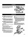
SQUARING
THE MITER
FENCE
See Figures 13- 16.
TABLE
TO THE
• Unplug your saw.
• Push down on the sew arm and pu[I out the lock pin to
release
the saw arm.
• Raise saw arm to its fult raised position.
• Loosen the miter lock levers.
• Rotate the miter table untTIthe pointer is positioned
atO'.
• Securelytighten the miter lock levers.
• Lay a framing square fiat on the miter table. Place one
tag of the square against the fence. Pla.cethe other
(eg of the square beside the throat plate in the miter
table. The edge of the square and the slot in the throat
plats in the miter table shouldbe parallelas shown in
figure 13.
• If the edge of the framing square and the throat plate
in the miter tabfe are not paraliefas shown in figures 14
and 15, adjustments are needed.
• Using the blade wrench, loosen the socket head
screws securingthe fence. Adjust the fence left or right
untilthe h'amlngsquare and throat plate are paraReL
THROATPLATE
VIEWOFMITERTABLENOTSQUARE
WITH
FENCE,ADJUSTMENTS
AREREQUIRED
F_g.f 4FRAMING
SOUARE
• Retighten the screws securelyand recheck the fenceto-table alignment,
FRAMING
SQUARE
FENCE
THROATPLATE
VIEWOFMITERTABLENOTSQUARE
WITH
FENCE,ADJUSTMENTS
AREREQUIRED
FENCE
Fig. 15
MITERTABLE
SOCKET
HEAD
SCREW(S)
SOCKFTHEAD
SCREW(S)
THROATPLATE
VIEWOFMITERTABLESQUAREWITHFENCE
CORRECTLY
ADJUSTED
Fig. 13
Fig. 16
17
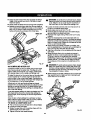
SQUARINGTHE SAW BLADETO THE FENCE
FENCE
See Figures 17 - 20.
• Unplug your saw.
•Pu[[ the saw arm a[I the way down and engage the lock
p_nto hold the saw arm in transport position.
• Loosen the miter lock Ievere.
•
Ro_ztethe miter table unti[the pointer is positioned
at0".
•
Securely tighten _le miter [ook levers.
•
Lay a framing square fiat on the miter table. Place one
leg of the square against the fence. Slide the other leg
of the square against the fiat paTtof saw blade.
NOTE: Make sure that the square contacts the fiat pert
of the saw blade, not the blade teeth.
BASE
VIEWOFBLADENOTSQUARE
WITH
FENP..,E,
ADJUSTMENTS
APEREQUIRED
• The edge of the square and the saw blade should be
parallelas shown in figure 17.
• If the front or back edge of the saw blade angles away
from the square as shown in figures 18 and 19, adjustmerits are needed.
•
FRAMING
SQUARE
Fig. 18
FENCE
BLADE
Using a 14 mm wrench, loosen the hex screws that
secure the mounting bracket to the miter table.
• Rotate the mounting bracket lei_tor right untilthe saw
blade Lspara.[[e(w}th the squaze,
• RatJghtenthe screwssacure[y and recheck the b[adeto-fence alignment.
FRAMING
SQUARE
FENCE
BASE
VIEWOFBLADENOTSQUARE
WITH
FENCE,ADJUSTMENTS
AREREQUIRED
F_.lg
BASE
HEXHEAD
FRAMING
SQUARE
VIEWOFBLADE
SQUAREWITH FENCE
Fig. 17
MOUNTING
BRACKET
MI'I'ER
TABLE
Fig. 20
18
SQUARINGTHE BLADETO THE
MITERTABLE
FENCE
See Figures21 - 24.
• Unplug yoursaw.
• Puffthe saw arm all the way down and engage the lock
pin to hold the saw arm In transportposition.
• Loosen the miter lock {avers.
•
Rotate the miter table untUthe pointer is positioned
_t0".
•
•
Securelytighten the miter Locklevers.
Loosen bevel lock knob and set saw arm at 0"bevel
(io)adeset g0"to miter table)."nghtenbevel lock knob.
•
Place a combinationsquare against the miter table and
the fiat part of saw b{ade.
MITER
TABLE
COMBINATION
SQUARE
CORRECT
VIEWOFBLADE
SQUAREWITHMITERTABLE
NOTE: Make sure that the square contacts the fiat part
of the saw blade, not the blade teeth.
• Rotate the blade by hsnd and check the blade-to-table
alignment at severe{
points.
FENCE
FiO.
BLADE
• The edge of the square and the saw bladeshould be
paraIle&as shown in figure21.
•
If the top or bottom of the saw blade angles away from
the square es shown in figures22 and 23, adjustments
ere needed.
• Using a 10 mm wrench or adjustable wrench, loosen
the lock nut sscur(ng positive stop adjustmentscrew.
ALsoloosen beve_lock 'Knob.See F_gum23.
MITER
TABLE
• Adjust positive stop adjustment screw to bring
saw blade Into alignmentwith the square.
•
COMBINATION
SQUARE
Retighten bevel lock knob. Next, retightenlock nut
securingthe positive stop ad,h._tmsntscrew. Recheck
bk_de-to-tsb{e alignment.
VIEWOFBLADENOTSQUAREWITHMITER
TABLE,AOJIJSTMENTS
AREREQU(REO
NOTE: The above procedure can be used to check
blade squareness of the saw blade to the miter table at
both 0"and 45"angles.
F(g. 22
POSITIVE
8TOP
ADJUSTMENT
SCREWFOR
45"ANGLES
LOCK
J
19
FIG.23
Yoursawhastwoscaleindicators,
oneonthebevelscale
andoneonthemiterscale.Aftersquaring
adjustments
havebeenmade,it may be necessaryto loosenthe indi-
FENCE
BLADE
cators screws end reset them to zero.
COMBINATION
SQUARE
MITER
TABLE
VIEWOFBLADENOTSQUARE
WiTHMITER
TABLE,ADJUSTMENTS
AREREQUIRED
CU'I-rlNG
SAW
_1, WARNING" Do not allow familiarity with yourtool
to make you careless.Remember that a careless
fraction of a second is sufficient to inflict severe
injury.
_,
WARNING: Always wear safety goggles or safety
glasseswith side shieldswhen oparat]ngtools.
Failureto do so could resultin objects being thrown
into your eyes, resulting in possibleserious injury.
A
WARNING: Do not use _ny attachments or accessories not recommended by the manufacturer of
this tool The use of attachments or scceseorise not
recommended can result in serfous persona| fnJ'ury.
_k
WITH
YOUR
COMPOUND
Fig. 24
MITER
WARNING: When using a work clamp or C-clamp
to secure yourworkpisce, clamp workpisce on one
side of the blade o_y. The workpisce must remain
_'ee on one side of the bradsto prevent the blade
from bindingin workpisoe.The workpiece binding
the blade will cause motor stallingand kickback.
This situationcould cause an accident resultingin
possibleserious personalinjury.
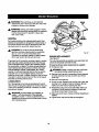
CROSSCU'n'ING
See Figure 25.
A crosscutis made by cuing across 1hegrain of the
workplace. A sVa",ghtcrosscutis made with the miter
table set at the 0" position.Miter crosscutsere made with
the miter table set _t some angte other than zero.
APPLICATIONS
Thisproduct has been designedonlyfor the purposeslisted
below:
• Cross cutting wood and plastic.
• Cross cutting miters, joints, etc. for pictureframes,
moldings, door casings, and fine jotnery.
• Bevel cutting and compQundcutting.
NOTE=The blade provided is fine for mostwood cutting
operations,but for fine jofnerycuts or cutting pisstlc, use
one of the accessory blades available from your nearest
Sears store.
_,
_TRAIGHT
CRD38CLIT
WARNING: Before stetting any cutting operation,
_brnp or bolt your compound miter saw to a
workbench. Never operate your miter saw on the
floor or in s crouched position.Failureto heed this
warning can resultin serious personalinjury.
Fig. 25
2O
TO MRrERCUT
• Pullout the lock pin and lift saw arm to its full height.
• Loosen the miter lock levers.
• Rotate the saw table until the pointer alignswith the
desired angle on the miter scale.
• Tighten the miter lock levers securely.
_k
• Rotate the saw table untilthe pointeraligns with zero
on the miter scale.
• Tighten the miter lock leverssecurely.
_lb WARNING: To avoid serious personalinjury,always
tighten the miter lock lever securelybefore makinge
cut. Failureto do so could resultin movement of the
controlarm or miter tabte while makinga cut.
WARNING: To avoid serious personalinjury, always
tighten the miter lock handle securely before making
a cut. Failureto do so could result in movement of
the controlarm or miter table while makinga cut.
MOUNTING
BRACKET
INDICATOR
POINT
• place the workpiece flat on the miter table with one edge
securely againstthe fence. If the board is warped, placa
the convex side against the fence. If the concave edge
of a board is pisced against the fence, the board could
collapse on the blade at the end of the cut, jamming the
blade.
• When cutting long pieces of lumber or molding, support
the opposite end of the stock with a relier stand or with
a work surface isve( with the saw tabte. See Figure 30.
• Aligncutting line on the werkplece with the edge ot saw
blade.
• Grasp the stock firmly with one hand and secure
it against the fence or use the optional work clamp or a
C-clamp to secure the wcrkplece.
_L
WARNING: To avoid seriouspersonal injury,keep
your hands outside the no hands zone; at least 3
in. from blade. Never perform any cutting operation
freehand (withoutholdingworkpisoa against the
fanoa). The blade could grab the workpieoaif it slips
or twists.
•
Beforeturningon the saw, performa dry runofthe cutting
operation just to make surs that no problemswilt occur
when the cut is made.
Fig. 26
•
Loo_¢ the bevel lock knob end move the saw arm to
the left to the desired bevel angle.
• Bevel engles can be sat from 0"to 45".
• Align the indioator point for the desired angis.
• Once the saw arm has been set at the das_'edangle,
seou_ly tighten the beve_lock knob.
•pisce the workpiace flat on the miter table with one
edge escurotyagainst the fence, it the board is warped,
place the convex side againstthe fence. If the concave
edge of a board is placed againstthe fence, the board
could collapseon the blade at ths end of the cut, jamming the blade.
• When cutting long pieces of lumber or molding, support the opposite end of the stock with a roller
stand or with a work surface [eve]with the saw table.
See F-Tgure30.
• Alignthe cutting lineon the workpiecawith the edge of
saw b_de.
• Grasp the stock firmlywith one hand and secureit
against the fence or use the optional work clamp or a
C-oiamp to secure the workpleoa.
• Grasp the saw handle firmly then squeeze the switch
kiggsr. Allow several seconds for the blade to reach
maXimumspeed.
• Slowly lower the blade into and throughthe workpieoa.
• Releasethe switchtriggerand allow the saw bledetostop
rotating before raisingthe blade out of workpisca. Wait
until the eiscb'icbrake stops blade from turning before
removingthe workplece from the miter table.
TO BEVEL CUT
see Figures26 - 27.
A bevel cut Is made by cutting across the grain of the
werkpisce with the bradeangled to the workpleoa. A
straight bevel cut is made with the miter table set at the
zero degree positionand the blade sot at an angle
between 0"and 45".
_1_ WARNING: To avoid serious personalinjury,keep
your hands away from Guttingarea. Never perform
,,ny cuffing operation freehand(without holding
workpisce against the fence}. The btade could grab
the workpisoa if it slips or twists.
•
• Pull out the (ock pin and riftsaw arm to its full height.
• Loosen the miter lock levere.
21
Beforeturning on the saw, perform a dry run of the cutting operationjust to make sure that no problemswill
occur when the cut Is made.
• Grasp the saw handle firmlythen squeeze the switch
trigger.Aflowseveral secondsfor the blade to reach
maximum speed.
• S1owlylower the blade into and throughthe workplece.
• Release the switch triggerand allow the saw blade to
stop rotating beforeraisihgthe blade out of workplace.
Wait untilthe electric brake stops blade from turning
before remo,_in_the wark_iece fro_'nmiter table.
WARNING: To avoid seriouspersonal injury,always
tightenthe miter lock levers securelybefore making
a cut. Failureto do so could result in movement of
the controlarm or miter table while making a cut.
•
•
•
BEVELCUT
•
•
•
•
•
Loosenthe bevel lock knob and move the saw arm to
the {eft to the desired bevel angle.
Bevel angtes can be set from 0° to 45 °.
Once the saw arm has been set at the desiredangle.
securelyt{ghtenthe bevel lock knob.
Recheck mher angle setting. M_e a test out in scrap
mstedaL
Place the workpiece flat on the miter table with one
edge securelyagainst the fence. If the board is warped,
place the convex side against the fence. If the concave
edge of a board could collapse on the blade at the end
of the cut, jamming the blade.
When cutting long pieces of lumber or molding,support the opposite end of the stock with a rollerstand or
with a work surface ]evelwith the saw table.
Alignthe cutting line on the workplece with the edge of
saw blade.
Grasp the stock firmly with one hand and secure It
against the fence or use the optionalwork clamp or a
C-clamp to secure the workplace when possible.
NOTE When maLdnga 45" left miter and a bevel angts
greater than 30", you must use a C-cismp to secure
the workpiece or move clamp to the right side of the
base.
Fig. 27
TO COMPOUND
_1= WARNING: To avoid seriouspersor_ injury, always
keep your handsaway from cutting area. Never perform any cutting operationfreehand (wiLhoutholding
workpiece againstthe fence). The blade could grab
the wed<pieceif it slipsor twists.
MITER CUT
A compound miter cut is e cut made usinga miterangle
and a bevel angle at the sarhe time. This type of cut is
used to make picture frames, cut molding,make boxes
with sloping sides, end for certain roof framing cuts.
•
To make this type of cut the conVol arm on the miter table
must be rotated to the correct angle and the saw arm
must be tilted to the correct bevel angle. Care shouldalways be taken when making compound miter setups due
to the interaction of the two angle settings.
Beforeturning on the saw. perform a dry run of the cutting opera,|oni_ to make sure tha_no probk_nswilt
occur when the cut is made.
Adjustments of miter and beveJsettings are interdependent with one another.Each time you adjust the miter
setting you change the effect of the bevel setting. Also,
each time you adjust the bevel setting you change the effect of the miter setting.
It may take several settingsto obtain the desiredcut. The
first angle setting should be checked after setting the
second angle, since adjusting the secondangle affects
the first.
Once the two correct settings for a particularout have
been obtained, always make a test cut in scrap material
beforemaklng a finish cut in good material.
TO MAKE A COMPOUND
CUT
• Puffout the lock pin and rift saw arm to its full height.
• Loosen the miter lock levers.
• Rotate the saw table untilthe pointeraligns with the
desired angle on the miter scala.
• Tighten the miter lock levers securely.
Fig.
28
22
• Grasp the saw handle firmlythen squeeze the switch
trigger.Allow several seconds for the blade to reach
m_x_mum speed.
•
Slowly lowerthe blade into and through the workp(ece. See/:{gum 28.
•
Release the switch trigger and allow the saw bladeto
slop rotatingbefore raisingthe blade out ofworkpiece.
Wait untilthe electric brake stops blade from turning
before removingthe workpiece from miter table.
SUPPORT LONG WORKPIECES
See Figure 30.
Long workpiecas need extra supports. Supportsshould
be placed along the work,piece so it does not sag. The
support should let the workplace lay fiat on the base
ot the saw and work table duringthe cutting operation.
Use the optional work c[,_Tlpor a C-clamp to secure the
workplace.
A
WARNING: To avoid seriouspsreona_injury, always
keep your hands outside the no hands zone; at least
3 in, from blade. Never perform any cutting operatfon
freehand (withoutholdingworkpiece against the
fencel. The bhde coutd grab the workplace if It sl(ps
or twists.
45"X 45"COMPOUND
MITERCUT
Fig. 29
LONGWORKPIECE
WORKPIECE
_LIPPOITI_
Fig. 30
23
CUTTING COMPOUND
MITERS
"toa_din makingthe correct settings,the compound angle se_ing chart botowhas been provided.Since compound cuts
are the most difficultto accurately obtain,trial cuts should be trade in scrap material, and much thoughtand plannfng
made, priorto making your requiredcut.
prrcH
NUMB-:R
ol:=o,=
4
I
5
OF $1DE,_
6
I
7
I
8
I
9
I
10
0o
M-45.00 ° M-36.00 °
B- 0,00 ° B0,00 =
M-30,00 =
B- 0.00 =
M-25.71 = , M-22.50 =
B- 0.00 ° B- 0.00 °
5=
M-44.89 = M.35.90 °
B" 3,53 = B- 2.94 -=
M-29,91 =
B,- 2.50 =
M-25.63 =
B- 2.17 =
M-;?.2.4.2 == M-19.93 °
B- 1.91 ° B- 1.71 =
10 °
M-44.56 °
B- 7.05 °
M-35.58 =
B- 5.86 °
M-29.62 °
B- 4.98 °
M-25.37 °
B- 4.32 °
M-22.19 =
B- 8,81 =
M-19.72 = M-17.74 °
B- 3.40 ° ]_- 3.08 °
1'5°
_-44,01 = M-35.06 °
B-10.55 Q B- 8.75 °
M-29.15 =
B- 7,44 °
M-24,85 =
B- 6,45 =
M-21.81 °
B- 5.68 °
M-19.37 =
B- 5.08 °
M-34,32 ° ;M-28.48 °
_-_1.60 °
B- 9,85 °
M-24.35 =
B- 8.53 °
M-21.27 = M-18.88 = M-16.98 =
B- 7.52"
B- 6.72 ° B,- 6.07 =
20=
M-43.22 °
B-'_4.00 °
M-20.00 ° M- 18.00 ° :
B0.00 ° B- 0.00 =
M-17.94 =
B- 1.54 °
M-17.42 °
IB- 4.59"
25 °
M-42.19 = M-33.36 °
B-17.39 ° B-14,38 °
M-27.62 °
B-12.20 °
M-23.56 °
B-10.57 °
M-20.58 ° M-18.26 °
B- 9.31 ° B- 8.31 °
M-16.41 °
B- 7.50 =
300
M-40.89 °
B-20.70 °
M-26.57=:
B-14.48 °
M-22.84 °
B-12,53 °
M-19.73 °
B-11,03 °
M-17.50 °
B- 9.85 °
M-15.72 =
B- 8,89 °
35 °
M-39.32 = M-30.76 =
B-23,93 ° B- 19.70 =
M-25.31 =
B- 16.67 °
M-21.53 °
B- 14.41 °
M-18.74 °
B- 12,68 °
M-16.60 °
B- 11.31 _
M-14.90 °
B- 10.21 =
40"
M'37'45=
B- 27.03"
M-2g'_0°
B- 22.20 q
M'23'86°
B- 18.75 °
M'20"25=
B- 16.19 =
1_'17"6G°
B- 14.24 °
M'15"56°
B- 12.70 q
M'13'98=
B- 11.46 °
45"
M-35.28 ° M-27.19 °
B- 3O.O0° B-24,56 °
M-22.21 °
B-29.70 =
M-18.80 =
B-17,57 °
M-16.32 °
B-15.70 =
M-14.43"
6-14.00 °
M-12,94'
6-12,62 °
M-32.73 °
B-32.80 °
M-25.03 =
B-26.76 °
M-20.36 °
B-22.52 °
M-17.20 °
B-19.41 °
M-14,91 ° IM-13.17 °
B-17.05 ° B-15.19°
M-11.80 =
B-13.69 =
55 =
M-28.84 °
B-35.40 °
M-22.62 =
B-28.78 °
M-'t8.32 °
B-24,18 =
M-15.44 o M-13,36 = M-11.79 °
B- 20.82 `> B-18.27 ° B-18.27 °
M-10.56 o
B-14.66 °
60 °
M-26.57 ° M-19.96 °
B-3736 ° B-30.60 °
M-18.10 °
B-25._6 °
M-13,54 °
B-99.07 °
M-11.70 = M-10.31 °
B-_9.35 = B-17.23 °
M- 9.23 =
B-16.52 °
65 °
M-22,91 = M-17,07 =
B- 39.86 ° B- 32.19 °
M-13,71 =
B- 25.95 _
M-11.50 =
B- 23.16 °
M- 9.93 °
13-20.29"
M- 8.74"
13-18.06 °
M- 7.82 °
B -16.26 °
70 =
M-18.88 = M-13.95 =
B-41.64 ° B- 33.53 =
M-11.17 °
B-28.02 °
M- 9.35 =
B- 24.06 =
M- 8.06 =
B-21.08'
M- 7.10 =
B- 18.75 =
M- 6.34 °
B- 16.88 °
75 °
M-14.51 °
B- 43.08 °
M-10.65 °
B-34.59 =
M- 8.50 °
B-28.88 =
M- 7.10 °
B-24.78 =
M- 6.12 = M- 5.38 °
B- 21 .Cog
= B- 19.29 =
M- 4.81 °
13- 17.37 =
80 °
M- 8.85 °
B" 44.14 =
M" 7,19 =
B-35.37 °
M- 5.73 =
B-29.50 °
M" 4.78 =
B-25,30 °
M- 4.11 °
B" 22.14 °
M" 3,62 = M" 3.23 °
13"19.68 ° B" 17.72 °
M-
M-
M-2.07
M-1,82
50°
M85 °
90 °
M-32.18 =
B-17.09 °
4.98 ° M-
3.62 =
B. 44.78 o 18-35.84o
I M- 0.0O° M0.00 °
6- 45.00 = B- 36.00 =
2.88 °
2.40 °
°
°
B-19.92 °
M-
1.62 =
B-29.87 °
B-25.61 °
B-22.41 °
M- 0.00 =
B- 30.00 °
M- 0,00 =
B- 25.71"
M.- 0.00 _ M- 0.00 ° M0.00 =
B- 22.50 ° B- 20.00"
B- 18.00 °
Each B (Bevel)and M (_iter) Setting is Given te the Closest 0.005°.
COMPOUND-ANGLE SETTINGS FOR POPULAR STRUCTURES
24
1_.17.93 °
CUT'rING CROWN MOLDING
Your compound mRer saw does an excellent Jobof cutting
crown molding. In general, compound miter saws do a
better job of cutting crownmolding than any other tool
made.
When setting the bevel and miter angles for compound
miters, rememberthat the settingsare interdependent;
changing one angle changes the other angle as well.
Keep in mind that the angles for crownmoldings are very
precLseand diffLcuitto sat. Since it tsvery easy for these
angles to shift, all settings should first be tested on scrap
molding.Also most wells do not have angles of exactly
90", therefore, you witl need to fine tune yoursettings,
In order to fit properly,crown molding must be compound
mitered with extreme accuracy.
The two contact surfaces on a piece of crown molding
that fit flat against the ceilingand the wall of a room are at
angles that, when added together, equal exactly go'. Most
crown molding has a top rear angle (the section that fits
fiat against the cs[Ting)of 52"and a bottom rear angle (the
section that fits fiat against the wall) of 38".
When cutting crown molding by this method the bevel
angle should be set at 33.85".The miter angle shouldbe
set at 31.62" either dght or left, dependingon the desired
cut for the application. See the chart below for correct
angle settings and correct positioningof crownmolding
on miter _ble.
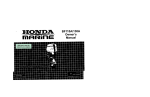
LAYING MOLDING
FLAT ON THE
MITER TABLE
See Figure 31.
"1"o
usethis method for accucateLycut_mg crownmolding
for a 90"inside or outside corner,lay the molding with its
broad back surface flat on the miter table and against the
fence.
52"
The settings in the chart below can be used for cutting All
Standard (U.S.) crownmolding with 52"and 38"angles.
The crown motdthgis plaoe(i fiat on the miter table us'rag
the compound features of your miter saw.
CEILING
INSIDE
CORNER
TOPEDGEAGAINSTFENCE=
* LEFTSIDE,IH$IDE¢6RNER
•
RIGHTSIDE,OWSIDECONNER
FEHCE
•
•
MITERTABLE
0
OUTSIDE
CORNER
0
BOTTOMEDGEAGAINSTFENCE=
RIGHT81DE,iNSIDECORNER
LEFTSLOE,OUTStOE
CORNER
MITERTABLE
0
0
CROWNMOLDINGFLATONMITERTABLE
F(g. 31
25
Bevel
Angle
Typeo#Cut
Setth_g
33.85"
33.85"
33.85"
side, inside comer
1. Top edge.of molding against fence
2. Miter table set fight 31.62"
3. Save left end of cut
Right side, Irmlde comer
1. Bottom edge of molding against fence
2. Miter table set left 31.62"
3. Save (eft end of cut
Left side, outside corner
_. Bottom edge of motding against fence
2. Miter tsble set left 31.62"
WRONG
Fig.33
3. Save right end of cut
33.65"
Right aide, outside comer
1. Top edge of molding against fence
2. Miter table set right 31.62"
3. Save right end of cut
_,
WARNING: To avoid a kickback and to avoid
seriouspersona_injury,never positionthe concave
edge of bowed or warped marsala[ against the fence.
CLAMPING
WIDE WORKPIECES
8ee Figure 34.
CUTIBNG WARPED
See Figures32 - 34.
MATERIAL
When cutting wide workpiecas such as a 2 in, x 6 in.,
boards should be clamped with a C-clamp as shown in
figure 34.
When cutting warped material, always make sure it is
positionedon the miter table with the convex side against
the fence as shown in figure 32.
If the warped material _spositionedthe wrong way as
shown in figure 33, it will pinch the blade near the completion of the out.
RIGHT
Fig. 32
Fig. 34
26
BEVEL PIVOT ADJUSTMENT
_1_ WARNING: Before performingany adjustment,
make sure the tool is unplugged from the power
supply and the switch is in the OFF ( O ) position.
Failureto heed this warning could result in serious
personalinjury.
• Yourcompound miter saw should bevel easily by loosening the bevel lock knoband tiltingthe saw arm to the
left.
• If movement is tight or if there is play in the pivot, have
saw repaired by a qualifiedservicetechnician at your
nearest Sears store or repair center to avoid risk of
personalinjury.
POSITIVESTOP
ADJLIS'TMENT
SCREWFDR
45"/i_GLE8
DEPTH STOP
See Figure 35.
The depth stop limits the blade's downward b'avel.It
allows the blade to go balow the rn_artable enough1o
maintain full cutting sapacitles. The depth stop positions
the blade 1/4 in. from the miter table support.
NOTE; The miter table support is located inside miter
table.
LOCK
The depth stop is factory set to providemaximum cutting
capacity for the "tOin. saw blade providedwith yoursaw.
Therefore, the saw with blade provided shouldnever need
adjusbx_ents.
However, when the diameter of the blade has been reduced due to sharpening,it may be necessary to adjust
the depth stop to providemaximum cutting capacity. ALso,
when a new blade is installed,it is necessaryto check the
clearanos of the blade to the miter table supportbefore
start'rngthe saw. Make adjustmentstf needed.
J
Fig. 35
PIVOT ADJUSTMENTS
NOTE; These adjustments were made at the factory and
normallydo not requirereadjustment.
TRAVEL
PIVOT ADJUSTMENT
• The saw arm should rise completelyto the up position
by itaeif.
• If the saw arm does not raise by itself or if there is play
in the pivot joints, have saw repaired by a qualified
service technician at your nearest Sears store or repair
center to avoid r_skof personal tn)ury.
27
DEPTH STOP ADJUSTMENTS
See Figure 36.
OEPTHSTOP
ADJUSTMENT
8CREW
•
A
Unplugyour saw.
WARNING" Failureto unplug yoursaw could result
in accidents| starting causing possibleserious
personal injury.
• To adjust the depth atop usaa 10 mm wrench or adjustable wrench and Loosenthe hex nut at the rear of
the miter saw arm.
MITER
TABLE
Use a 5 mm hex key wrench to adiuat the depth stop
adjus_ent screw. The saw h_adele lowered by turning
the screw counter-c[ook'wkse
and raised by turning the
screw clockwise.
Lowerthe blade intothe miter table. Check brads
clsarance and maximum cutting distance (distance
from fence where blade enbars)_ front of miter table
slot.
• Readjust if necessary.
• Tighten the hex nut with a 10 mm wrench or adiustable
wrench.
POSITIVE
STOP
ADJUSTMENT
SCREW
FOR
O"ANGLES
• To prevent the depth stop adjustmentscrew from turning while tighteningthe hax nut, carefuJ]yhold Jtwith
the hax key wrench while tighteningthe hax nut.
LOCKNUT(S)
Fig. 36
WARNING:. Do not start youTcompound miter saw
without checking for interferencebetween the blade
and the throat plate, Damage could resultto the
blade if it strikes the throat plate during operation of
the saw.
28
BRUSH
CAP
_l_ WARNING: When servicing, use onlyidentical
replacement parts. Use of any other part may create
a hazard or cause productdan'_ge.
AI_ WARNING: Always wear safety gogglus or safety
glasseswith side shields during power tool operation
or when blowing dust. If operation is dusty,also
wear a dust mask.
BRUSH
AESEMBLY
BRUgd-I
ASSEMBLY
GENERAL
Avoid usingsolvents when cleaning p_sUo parts. Most
plasticsare susceptibleto damage fTomvarious bJpesof
commemialsolventsand m_y be damaged by theirusa.
Use clean clothsto remove dirt, carbon dust, etc.
BRUSH
CAP
_IL WARNING: Do not at any time let brake fluids,
gasoline, petroleum-basedproducts, penetrating
oils, etc. come in contact with plastic parts.
Chemicals can damage, weaken or destroyplastic
which may result in serious personal injury.
Fig. 37
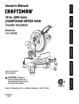
BRUSH REPLACEMENT
See Figure 37.
It has been found that electric tools are subject to accalarated wear and possibleprernaturelailurawhen they are
used on fiberglassboats, sportscars, wstiboard,spackling compounds, or plsstar.The chips and grindings_om
these materials are highlyabrasive to electric tool parts
such as bearings, brushes,commutators, etc. Consequently,it is not recommended that this tool be used for
extended work on any fiberglassmaterial, wallboard,
spackJIngcompounds, or piaster.During any use on these
materials it is extremely importantthat the tool is cleaned
frequently by blowingwith an air iet.
Your saw has externally accessiblebrush assembliesthat
should be periodicallycheck_edfor wear.
LUBRICATION
• Check for wear. Replace both brusheswhen eitherhas
less than 1/4 in. length of carbon remaining.Do not
replace one side without repfacingthe other.
• Reassemble using new brush assemblies.Make sure
curvature of brush matches curvatureof motor and
that brush moves freely in brush tubs.
• Make s_'s brushc_ is odented correctly (s_'aight)and
replace.
Proceed as follows when rapla¢emant Is required:
• Unplug your saw.
_k
• Remove brushcap with a screwdriver.Brush assembly
is springloaded end wLtlpop out when you remove
brush _,ap.
• Remove brush assembly.
Aft of the bearingsin this tool are lubricatedwith a sufficient amount of high grade lubricant for the life of the unit
under normal operating conditions.Therefore, no further
lubricationIs requlrad.
_IL
WARNING: Failureto unplug your saw could result
in accidental starting causing serious iniury.
WARNING: To ensure safety and raJJabJJil"_,
aJ_
repairs -- with the excaption of the externally
accessible brushes - should be performed by a
qualifiedservice technicianat a Sears store to avoid
risk of personalinjury.
• "l'ightenbrush cap securely.Do not overtighten.
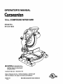
29
Your Home
For repair-In your home-of all major brand appliances,
lawn and garden equipment, or heating and cooling systems,
no matter who made It, no matter who sold Itl
For the replacement parts, accessories and
owner's manuals that you need to do-it-yourself.
For Sears professional installation of home appliances
and items like garage door openers and water heaters.
1-800-4-MY-HOME ® (1400-469-4663)
Call anytime, day or night (U.S_, and Canada)
_/._81'LCOm
re.sears.ca
Our Home
For repair of carry-in items like vacuums, lawn equipment,
and electronics, call or go on-line for the location of your nearest
Sears Parts & Repair Center.
1-800-488-1222
Call anySme, day or night (U,SJ_. only)
_.ZrM_'I_COIR1
To purchase a protection agreement (U.Sa_.)
or maintenance agreement (Canada) on a product serviced by Sears:
1-800-827-6655
(u.s_.)
Pare pedir servicio de repamci6n
a domicilio, y para ordenar piezas:
1-888.SU.HOGAR
s"
1-800-361-6665
(Canada)
Au Canada pour service en franQais:
1-800-LE-FOYER uc
(1-8oo-533-6937)
(1-888-784-6427 q)
® Reglst8red Tradema_ / _ Trademaz-kI _ Se_loe Marko__m, RoebuckandCo,
® Marca Regb_ada / "raMarca de FJbdca/ =* Marca de Servldo de _Hm=, Roel_ck _
_ Ma_ue de _mmerce f u" Msro_e d_poz_e de _
RoeSucksndCo.
WWW.sears.ca
_.
©Seans, Roebuc_snd Co.