1
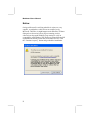
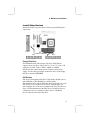
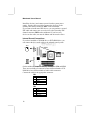
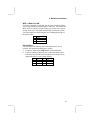
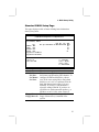
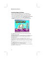
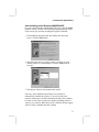
Mainboard User’s Manual
This publication, photographs, illustrations and software are under
the protection of international copyright laws and all rights
reserved. It does not allow any reproduction of this manual,
content and any materials contained herein without the written
consent of the authentic manufacturer.
The information in this manual is subject to change without notice.
The manufacturer does neither represent nor warrant the contents
hereof; and specifically disclaims any implied warranties of
merchantability or fitness for any particular purpose. Furthermore,
the manufacturer reserves the right to revise and change this
publication from time to time, without the obligation of notifying
any person of such revision or changes.
Trademarks
IBM, VGA, and PS/2 are registered trademarks of International
Business Machines.
Intel, Pentium/II/III, Pentium 4, Celeron and MMX are registered
trademarks of Intel Corporation.
Microsoft, MS-DOS and Windows 98/ME/NT/2000/XP are
registered trademarks of Microsoft Corporation.
PC-cillin is a trademark of Trend Micro Inc.
AMI is a trademark of American Megatrends Inc.
MediaRing Talk is a registered trademark of MediaRing Inc.
3Deep is a registered trademark of E-Color Inc.
It has been acknowledged that all mentioned brands or product
names are trademarks or registered trademarks of their respective
holders.
Copyright © 2002
All Rights Reserved
KOB 845GL NDSMx
V3.1
I845GL/May 2002
P/N: 40-012-D86311
Mainboard User’s Manual
Notice:
Owing to Microsoft’s certifying schedule is various to every
supplier, we might have some drivers not certified yet by
Microsoft. Therefore, it might happen under Windows XP that a
dialogue box (shown as below) pop out warning you this
software has not passed Windows Logo testing to verify its
compatibility with Windows XP. Please rest assured that our RD
department has already tested and verified these drivers. Click
the “Continue Anyway” button and go ahead the installation.
II
Mainboard User’s Manual
Table of Contents
Chapter 1: Introduction ...................................................................1
Key Features............................................................................2
Package Contents ....................................................................5
Static Electricity Precautions...................................................6
Pre-Installation Inspection.......................................................6
Chapter 2: Mainboard Installation...................................................7
Mainboard Components ..........................................................8
I/O Ports ..................................................................................9
Installing the Processor..........................................................10
Installing Memory Modules ..................................................11
Jumper Settings .....................................................................13
Install The Mainboard ...........................................................14
Optional Extension Brackets .................................................16
Install Other Devices .............................................................17
Expansion Slots ....................................................................20
Chapter 3: BIOS Setup Utility.......................................................21
Introduction ...........................................................................21
Running the Setup Utility........... …………………………...22
Standard CMOS Setup Page..................................................23
Advanced Setup Page ............................................................24
Power Management Setup Page ............................................27
PCI/Plug and Play Setup Page...............................................29
Load Optimal Settings...........................................................30
Load Best Performance Settings ...........................................30
Features Setup Page...............................................................31
CPU PnP Setup Page .............................................................33
Hardware Monitor Page ........................................................34
Change Password ..................................................................34
Exit ........................................................................................34
Chapter 4: Software & Applications .............................................35
Introduction ...........................................................................35
Installing Support Software...................................................36
Bundled Software Installation ...............................................38
Appendix ...............................................................................39
III
Mainboard User’s Manual
IV
1: Introduction
Chapter 1
Introduction
This mainboard has a Socket-478 support for Intel Pentium4
processors with front-side bus (FSB) speeds up to 400 MHz.
This mainboard has the Intel 845GL chipset that contains Intel
82845 Memory Controller Hub and Intel 82801 I/O Controller
Hub. It supports built-in USB 2.0 providing higher bandwidth.
It implements Universal Serial Bus Specification Revision 2.0
and is compliant with UHCI 1.1 and EHCI 0.95. This mainboard
supports AC 97 audio codec and provides Ultra DMA 33/66/100
function. This mainboard has two 32-bit PCI, one AGP1 (with
Digital Video Output, but without AGP support) and one CNR
(Communications and Networking Riser) slot. There is a full set of
I/O ports including two PS/2 ports for mouse and keyboard, one
serial port, one VGA port, one parallel port, one MIDI/game port
and maximum six USB ports(USB 2.0): two back-panel USB ports
and you can make four extra USB ports by connecting the
extended USB module to the mainboard.
This mainboard is an Micro ATX mainboard that uses a 4-layer
printed circuit board and measures 244 x 244mm.
1
Mainboard User’s Manual
Key Features
This mainboard has these key features:
Socket-478 Processor
♦ Supports Intel Pentium 4 series CPUs
♦ Supports up to 400 MHz Front-Side Bus
Memory Support
♦ Two 168-pin DIMM slots for SDRAM memory modules
♦ Two 184-pin DIMM slots for DDR SDRAM memory
modules
♦ Support SDRAM up to 133 MHz/DDR up to 266 MHz
memory bus
♦ Maximum installed memory is 2GB
Notice: YOU can NOT work SDRAM and DDR simultaneously.
AC97 Audio Codec: CMI9738
♦ Compliant with AC’97 2.2 specification
♦ Full-duplex Codec with independent and variable sampling
rate
♦ Earphone Buffer Built-In, SNR up to 90db
♦ 4Ch DAC, support 4-channel speak-out
♦ Advanced power management support
Expansion Options
The mainboard comes with the following expansion options:
♦ Two 32-bit PCI slots
♦ Supports IDE Ultra DMA bus mastering with transfer rates
of 33/66/100 MB/sec
♦ One DVO (without AGP support) slot
♦ One CNR (Communications and Networking Riser) slot
2
1: Introduction
Onboard I/O Ports
The mainboard has a full set of I/O ports and connectors:
♦ Two PS/2 ports for mouse and keyboard
♦ One serial ports
♦ One parallel port
♦ One VGA port
♦ One MIDI/game port
♦ Six USB ports (two back-panel USB ports, onboard USB
headers providing maximum four extra ports: header
USB2 and USB3)—all support USB 2.0
♦ Audio jacks for microphone, line-in and line-out
Fast Ethernet LAN
♦ Built-in 10BaseT/100BaseTX Ethernet LAN
♦ Integrated Fast Ethernet MAC and full compliance with
IEEE 802.3u 100 Base-T specifications and IEEE 802.3x
Full Duplex Flow Control
♦ In compliance with ACPI 1.0 and the Network Device
Class Power Management 1.0
♦ High Performance achieved by 100Mbps clock generator
and data recovery circuit for 100Mbps receiver
USB 2.0
♦ Compliant with Universal Serial Bus Specification
Revision 2.0
♦ Compliant with Intel’s Enhanced Host Controller
Interface Specification Revision 0.95
♦ Compliant with Universal Host Controller Interface
Specification Revision 1.1
♦ PCI multi-function device consists of two UHCI Host
Controller cores for full-/low-speed signaling and one
EHCI Host Controller core for high-speed signaling
♦ Root hub consists 4 downstream facing ports with
integrated physical layer transceivers shared by UHCI and
EHCI Host Controller
♦ Support PCI-Bus Power Management Interface
Specification release 1.1
♦ Legacy support for all downstream facing ports
3
Mainboard User’s Manual
BIOS Firmware
This mainboard uses AMI BIOS that enables users to configure
many system features including the following:
♦ Power management
♦ Wake-up alarms
♦ CPU parameters and memory timing
♦ CPU and memory timing
The firmware can also be used to set parameters for different
processor clock speeds.
Bundled Software
♦ PC-Cillin 2000 provides automatic virus protection under
Windows 98/ME/NT/2000/XP
♦ MediaRing Talk provides PC to PC or PC to Phone
internet phone communication
♦ 3Deep delivers the precise imagery and displays accurate
color in your monitor
♦ Recovery Genius 21st V5.0 provides the function to
recover, reserve and transfer hard disk data.
♦ CD Ghost is the software stimulating a real CD-ROM to
perform equivalent function.
♦ Language Genius 21st is the software to provides learning
tools of language and singing.
♦ PC DJ is a dual-MP3 player that enables users to actually
mix music right on their own personal computers.
♦ Adobe Acrobat Reader V5.0 is the software to help users
read .PDF files.
Dimensions
♦ ATX form factor of 244 x 244mm
4
1: Introduction
Package Contents
Attention: This mainboard serial has two models, KOB845GL
NDSMx and KOB845GL NDSMx ulr (USB 2.0, LAN Ready).
Please contact your local supplier for more information about your
purchased model. Each model will support different specification
listed as below:
Model
Specification
KOB845GL
Support USB connector only
NDSMx
KOB845GL
Onboard RTL8100 LAN chipset (U7),
NDSMx ulr
support USB 2.0 + RJ-45 LAN connector
Your mainboard package contains the following items:
The mainboard
The User’s Manual
One diskette drive ribbon cable
One IDE drive ribbon cable
Software support CD
Optional Accessories
You can purchase the following optional accessories for this
mainboard.
Extended USB module
CNR v.90 56K Fax/Modem card
5
Mainboard User’s Manual
Static Electricity Precautions
Static electricity could damage components on this mainboard.
Take the following precautions while unpacking this mainboard
and installing it in a system.
1. Don’t take this mainboard and components out of their original
static-proof package until you are ready to install them.
2. While installing, please wear a grounded wrist strap if possible.
If you don’t have a wrist strap, discharge static electricity by
touching the bare metal of the system chassis.
3. Carefully hold this mainboard by its edges. Do not touch those
components unless it is absolutely necessary. Put this
mainboard on the top of static-protection package with
component side facing up while installing.
Pre-Installation Inspection
1. Inspect this mainboard whether there are any damages to
components and connectors on the board.
2. If you suspect this mainboard has been damaged, do not
connect power to the system. Contact your mainboard vendor
about those damages.
6
2: Mainboard Installation
Chapter 2
Mainboard Installation
To install this mainboard in a system, please follow these
instructions in this chapter:
Identify the mainboard components
Install a CPU
Install one or more system memory modules
Make sure all jumpers and switches are set correctly
Install this mainboard in a system chassis (case)
Connect any extension brackets or cables to connecting
headers on the mainboard
Install other devices and make the appropriate connections to
the mainboard connecting headers
Note:
1. Before installing this mainboard, make sure jumper JP2 is
under Normal setting. See this chapter for information about
locating JP2 and the setting options.
2. Never connect power to the system during installation;
otherwise, it may damage the mainboard.
7
Mainboard User’s Manual
Mainboard Components
Identify major components on the mainboard via this diagram
underneath.
Note: Any jumpers on your mainboard that do not appear in
this illustration are for testing only.
8
2: Mainboard Installation
I/O Ports
The illustration below shows a side view of the built-in I/O ports
on the mainboard.
LAN
port
PS/2
mouse
PS/2
keyboard
USB
ports
Parallel port (LPT1)
Serial port VGA port
COM 1
VGA1
Game port
Microphone
Line-in
Line-out
1. The upper PS/2 port connects a PS/2 pointing
device.
2. The lower PS/2 port connects a PS/2 keyboard.
3. The USB ports connect USB devices.
4. LPT1 connects printers or other parallel
communications devices.
5. The COM port connects serial devices such as mice
or fax/modems; VGA port connects to graphic
display devices.
6. The game port connects a joystick or a MIDI
device.
7. Three audio ports connect audio devices. The left
side jack is for a stereo line-out signal. The middle
jack is for a stereo line-in signal. The right side jack
is for a microphone.
8. LAN port connects the network.
9
Mainboard User’s Manual
Installing the Processor
This mainboard has a Socket 478 processor socket. When choosing
a processor, consider the performance requirements of the system.
Performance is based on the processor design, the clock speed and
system bus frequency of the processor, and the quantity of internal
cache memory and external cache memory.
CPU Installation Procedure
Follow these instructions to install the CPU:
1. Unhook the CPU socket’s locking lever by pulling
it away from socket and raising it to the upright
position.
2. Match the pin 1 corner of CPU socket to the one of
processor, and insert the processor into the socket.
Do not use force.
3. Push the locking lever down and hook it under the
latch on the edge of socket.
4. Apply thermal grease to the top of the CPU.
5. Lower the CPU fan/heatsink unit onto the CPU and
CPU socket, and then use the retention module
clamps to snap the fan/heatsink into place.
6. Plug the CPU fan power cable into the CPU
cooling fan power supply connector on the
mainboard.
10
2: Mainboard Installation
Installing Memory Modules
This mainboard accommodates 168-pin 3.3V/184-pin 2.5V
unbuffered SDRAM memory modules. The memory chips must be
standard or registered SDRAM (Synchronous Dynamic Random
Access Memory).
The CPU supports 100MHz system bus. The SDRAM DIMMs
and DDRs can synchronously work with 100 MHz or operates over
a 133 MHz memory bus.
You must install at least one memory module in order to use
the mainboard, either SDRAM or DDR SDRAM, but you
cannot use them simultaneously.
Note: Please be noted you must set up the correct jumper settings
(JT1~JT11) as described in page 13 of this chapter.
SDRAM provides 800 MB/s or 1 GB/s data transfer rate
corresponding with the bus 100 MHz or 133 MHz. It doubles the
rate to 1.6 GB/s and 2.1 GB/s by transferring data on both the
rising and falling edges of the clock. DDR SDRAM uses additional
power and ground lines and requires 184-pin 2.5V unbuffered
DIMM module rather than the 168-pin 3.3V unbuffered DIMMs
used by SDRAM.
SDR1
DDR1
SDR2
DDR2
11
Mainboard User’s Manual
Installation Procedure
The mainboard accommodates two memory modules. You must
install at least one module in any of the three slots. Each module
can be installed with up to 2 GB system memory.
Refer to the following to install the memory modules.
1. Push the latches on each side of the DIMM slot
down.
2. Align the memory module with the slot. The
DIMM slots are keyed with notches and the
DIMMs are keyed with cutouts so that they can
only be installed correctly.
3. Check that the cutouts on the DIMM module edge
connector match the notches in the DIMM slot.
4. Install the DIMM module into the slot and press it
firmly down until it seats correctly. The slot latches
are levered upwards and latch on to the edges of the
DIMM.
5. Install any remaining DIMM modules.
12
2: Mainboard Installation
Jumper Settings
JP2
JT1
JT2
JT7
JT3
JT8
JT4
JT5
JT6
JT9
JT10
JT11
JP2: Clear CMOS Jumper
Use this jumper to clear the contents of the CMOS memory. You
may need to clear the CMOS memory if the settings in the Setup
Utility are incorrect and prevent your mainboard from operating.
To clear the CMOS memory, disconnect all the power cables from
the mainboard and then move the jumper cap into the CLEAR
setting for a few seconds.
Function
Normal
Clear CMOS
Jumper Setting
Short Pins 1-2
Short Pins 2-3
JT1~JT11: DDR/SDR DRAM Type Selector
This jumper enables to select DDR or SDR DRAM type.
Function
DDR
SDRAM
Jumper Setting
Short all JT1~JT11 pins
Open all JT1~JT11 pins
13
Mainboard User’s Manual
Install the Mainboard
Install the mainboard in a system chassis (case). The board is an
ATX size mainboard with a twin-tier of I/O ports. You can install
this mainboard in an ATX case. Ensure that your case has an I/O
cover plate that matches the ports on this mainboard.
Install the mainboard in a case. Follow the instructions provided by
the case manufacturer using the hardware and internal mounting
points on the chassis.
1
PW1
AUDIO1
1
PANEL1
CHS FAN
1
1
SPKR1
PLED1
Connect the power connector from the power supply to the PW1
connector on the mainboard.
If there is a cooling fan installed in the system chassis, connect the
cable from the cooling fan to the CHS FAN fan power connector
on the mainboard.
Connect the cable from the PC speaker to the SPKR1 header on
the mainboard.
Pin
1
3
14
Signal
SPKR
GND
Pin
2
4
Signal
NC
+5V
2: Mainboard Installation
Connect the case switches and indicator LEDs to the PANEL1
header. Here is a list of the PANEL1 header’s pin assignments.
Pin
1
3
5
7
9
Signal
HDD_LED_P
HDD_LED_N
RESET_SW_N
RESET_SW_P
KEY
Pin
2
4
6
8
10
Signal
ACPI-LED
ACPI-LED
POWER-BT
POWER-BT
KEY
If there are a headphone jack or/and a microphone jack on the front
panel, connect the cables to the AUDIO1 header on the mainboard.
Here is a list of the AUDIO header’s pin assignments.
Pin
1
3
5
7
9
Signal
AUD_MIC
AUD_MIC_BIAS
AUD_FPOUT_R
HP_ON
AUD_FPOUT_L
Pin
2
4
6
8
10
Signal
AUD_GND
AUD_VCC
GND
KEY
GND
If there is another power-on indicator LED installed in the
system chassis, connect the LED to the PLED1 header.
Pin
1
2
3
Signal
GROUND
NC
POWER
15
Mainboard User’s Manual
Optional Extension Brackets
For this mainboard, you can also obtain a USB module extension
bracket for more USB ports. Install them by following the steps
below.
Note: All the ribbon cables used on the extension brackets have a
red stripe on the Pin-1 side of the cable.
Extended USB Module
This module bracket has four USB 2.0 ports for more USB devices
(USB 2.0 port USB2, USB3).
1
USB2
1
USB3
Pin
1
3
5
7
9
Signal
VERG_FP_USBPWR0
USB_FP_P0USB_FP_P0+
GROUND
KEY
Pin
2
4
6
8
10
Signal
VERG_FP_USBPWR0
USB_FP_P1USB_FP_P1+
GROUND
NC
1. Locate the USB2/USB3 header on the mainboard.
2. Plug the bracket cable onto the USB2/USB3 header.
3. In the system chassis, remove a slot cover from one of the
expansion slots and install the extension bracket in the
opening. Secure the extension bracket to the chassis with a
screw.
16
2: Mainboard Installation
Install Other Devices
Install and connect any other devices in the system following the
steps below.
FLOPPY
IDE1
IDE2
Floppy Disk Drive
The mainboard ships with a floppy disk drive cable that can
support one or two drives. Drives can be 3.5” or 5.25” wide, with
capacities of 360K, 720K, 1.2MB, 1.44MB, or 2.88MB.
Install your drives and connect power from the system power
supply. Use the cable provided to connect the drives to the floppy
disk drive connector FLOPPY.
IDE Devices
IDE devices include hard disk drives, high-density diskette drives,
and CD-ROM or DVD-ROM drives, among others.
The mainboard ships with an IDE cable that can support one or two
IDE devices. If you connect two devices to a single cable, you
must configure one of the drives as Master and one of the drives as
Slave. The documentation of the IDE device will tell you how to
configure the device as a Master or Slave device. The Master
device connects to the end of the cable.
17
Mainboard User’s Manual
Install the device(s) and connect power from the system power
supply. Use the cable provided to connect the device(s) to the
Primary IDE channel connector IDE1 on the mainboard.
If you want to install more IDE devices, you can purchase a second
IDE cable and connect one or two devices to the Secondary IDE
channel connector IDE2 on the mainboard. If you have two
devices on the cable, one must be Master and one must be Slave.
Internal Sound Connections
If you have installed a CD-ROM drive or DVD-ROM drive, you
can connect the drive audio cable to the onboard sound system.
SIR1
1
1
CD1
CD2
WOL1
On the mainboard, locate the two 4-pin connectors CD1 and CD2.
There are two kinds of connector because different brands of CDROM drive have different kinds of audio cable connectors.
Connect the cable to the appropriate connector.
CD1
Pin
1
2
3
4
Signal
CD IN L
GND
GND
CD IN R
CD2
Pin
1
2
3
4
18
Signal
GND
CD IN R
GND
CD IN L
2: Mainboard Installation
WOL1: Wake On LAN
If you have installed a LAN card, use the cable provided with the
card to plug into the mainboard WOL1 connector. This enables the
Wake On LAN (WOL1) feature. When your system is in a powersaving mode, any LAN signal automatically resumes the system.
You must enable this item using the Power Management page of
the Setup Utility.
Pin
1
2
3
Signal
5VSB
GND
-RING
Infrared Port
You can connect an infrared port to the mainboard. You can
purchase this option from third-party vendors.
1. Locate the infrared port SIR1 header on the mainboard.
2. If you are adding an infrared port, connect the ribbon cable
from the port to the IR header and then secure the port to an
appropriate place in your system chassis.
Pin
1
3
5
Signal
NC
+5V
IRTX
Pin
2
4
6
Signal
KEY
GND
IRRX
19
Mainboard User’s Manual
Expansion Slots
This mainboard has one AGP, one CNR and two 32-bit PCI slots.
AGP1
CNR1
PCI2
PCI1
Follow the steps below to install a AGP/CNR/PCI expansion card.
1. Locate the AGP, CNR or PCI slots on the mainboard.
2. Remove the slot cover for this slot from the system chassis.
3. Insert the expansion card edge connector into the slot and press
it firmly down into it so that it is fully inserted.
4. Secure the expansion card bracket to the system chassis using
the screw that held the slot cover in place.
PCI Slots
You can install 32-bit PCI interface expansion cards in PCI slots.
Slot1 only supports PC5 Slave mode. It is recommended you give
first priority to PCI 1~4 slots while inserting cards.
AGP1
This slot supports the DVO (Digital Video Output) function
(without AGP support) for a TV or video monitor displaying.
CNR Slot
This slot is used to insert CNR (Communications and Networking
Riser) cards including LAN, Modem, and Audio functions.
20
3: BIOS Setup Utility
Chapter 3
BIOS Setup Utility
Introduction
The BIOS Setup Utility records settings and information of your
computer, such as date and time, the type of hardware installed,
and various configuration settings. Your computer applies those
information to initialize all the components when booting up and
basic functions of coordination between system components.
If the Setup Utility configuration is incorrect, it may cause the
system to malfunction. It can even stop your computer booting
properly. If it happens, you can use the clear CMOS jumper to
clear the CMOS memory which has stored the configuration
information; or you can hold down the Page Up key while
rebooting your computer. Holding down the Page Up key also
clears the setup information.
You can run the setup utility and manually change the
configuration. You might need to do this to configure some
hardware installed in or connected to the mainboard, such as the
CPU, system memory, disk drives, etc.
21
Mainboard User’s Manual
Running the Setup Utility
Every time you start your computer, a message appears on the
screen before the operating system loading that prompts you to
“Hit <DEL>if you want to run SETUP”. Whenever you see this
message, press the Delete key, and the Main menu page of the
Setup Utility appears on your monitor.
AMIBIOS SIMPLE SETUP UTILITY – VERSION 1.21.10
(C) 2000 American Megatrends, Inc. All Rights Reserved
Standard CMOS Setup
Advanced Setup
Power Management Setup
PCI / Plug and Play Setup
Load Optimal Settings
Load Best Performance Settings
Features Setup
CPU PnP Setup
Hardware Monitor
Change Password
Exit
Esc : Quit
↑ ↓ ← →: Select Item (Shift)F2 : Change Color F5 : Old Values
F6 : Optimal values
F7 : Best performance values F10 : Save&Exit
Standards COMOS setup for changing time, date, hard disk type, etc.
You can use cursor arrow keys to highlight anyone of options on
the main menu page. Press Enter to select the highlighted option.
Press the Escape key to leave the setup utility. Hold down the
Shift key and press F2 to cycle through the Setup Utility’s optional
color schemes.
Some options on the main menu page lead to tables of items with
installed values that you can use cursor arrow keys to highlight one
item, and press PgUp and PgDn keys to cycle through alternative
values of that item. The other options on the main menu page lead
to dialog boxes that require your answer Yes or No by hitting the Y
or N keys.
If you have already changed the setup utility, press F10 to save
those changes and exit the utility. Press F5 to reset the changes to
the original values. Press F6 to install the setup utility with a set of
default values. Press F7 to install the setup utility with a set of
high-performance values.
22
3: BIOS Setup Utility
Standard CMOS Setup Page
This page displays a table of items defining basic information
about your system.
AMIBIOS SETUP – STANDARD CMOS SETUP
(C) 2000 American Megatrends, Inc. All Rights Reserved
Date (mm/dd/yy) : Mon May 20, 2002
Time (hh/mm/ss) : 18:00:45
LBA Blk
PIO
Type
Size Cyln Head WPcom Sec Mode Mode Mode
Pri Master : Auto
Pri Slave : Auto
Sec Master : Auto
Sec Slave : Auto
Floppy Drive A : 1.44 MB 3 1/2
Floppy Drive B : Not Installed
Month : Jan – Dec
Day : 01 – 31
Year : 1901 – 2099
Date & Time
IDE Pri Master
Pri Slave
Sec Master
Sec Slave
Floppy Drive A
Floppy Drive B
32Bit
Mode
On
On
On
On
ESC : Exit
↑↓ : Select Item
PU/PD/+/- : Modify
(Shift)F2 : Color
F3 : Detect All HDD
These items set up system date and time.
These items configure devices connected to
the Primary and Secondary IDE channels. To
configure an IDE hard disk drive, choose
Auto. If the Auto setting fails to find a hard
disk drive, set it to User, and then fill in the
hard disk characteristics (Size, Cyls, etc.)
manually. If you have a CD-ROM drive,
select the setting CDROM. If you have an
ATAPI device with removable media (e.g. a
ZIP drive or an LS-120), select Floptical.
These items set up size and capacity of the
floppy diskette drive(s) installed in the
system.
23
Mainboard User’s Manual
Advanced Setup Page
This page sets up more advanced information about your system.
Handle this page with caution. Any changes can affect the
operation of your computer.
AMIBIOS SETUP – ADVANCED SETUP
(C) 2000 American Megatrends, Inc. All Rights Reserved
Quick Boot
1st Boot Device
2nd Boot Device
3rd Boot Device
Try Other Boot Devices
S.M.A.R.T. for Hard Disks
Floppy Drive Swap
Floppy Drive Seek
PS/2 Mouse Support
Password Check
L2 Cache
System BIOS Cacheable
SDRAM Frequency
SDRAM Timing by SPD
SDRAM CAS# Latency
SDRAM RAS# Precharge
SDRAM RAS# to CAS# Delay
SDRAM Precharge Delay
Spread Spectrum
Auto Detect DIMM/PCI Clk
Delay For Hard Drive (Sec.)
Quick Boot
1st Boot Device
2nd Boot Device
3rd Boot Device
Try Other Boot
Device
24
Enabled
IDE-0
Floppy
CD/DVD
Yes
Disabled
Disabled
Disabled
Enabled
Setup
Enabled
Enabled
133MHz
Enables
3 Clocks
3 Clocks
3 Clocks
7 Clocks
Disabled
Enabled
2
ESC
F1
F5
F6
F7
: Quit
↑↓←→ : Select Item
: Help
PU/PD/+/- : Modify
: Old Values (Shift)F2 : Color
: Load BIOS Defaults
: Load Setup Defaults
If you enable this item, the system starts
up more quickly be elimination some of
the power on test routines.
Use these items to determine the device
order the computer uses to look for an
operating system to load at start-up time.
If you enable this item, the system will
also search for other boot devices if it
fails to find an operating system from the
first two locations.
3: BIOS Setup Utility
S.M.A.R.T. for
Hard Disks
Floppy Drive
Swap
Floppy Drive
Seek
PS/2 Mouse
Support
Password Check
L2 Cache
System BIOS
Cacheable
SDRAM
Frequency
SDRAM Timing
By SPD
SDRAM CAS#
Latency
Enable this item if any IDE hard disks
support the S.M.A.R.T. (SelfMonitoring, Analysis and Reporting
Technology) feature.
If you have two diskette drives installed
and you enable this item, drive A
becomes drive B and drive B becomes
drive A.
If you enable this item, your system will
check all floppy disk drives at start up.
Disable this item unless you are using an
old 360KB drive.
Enable this item if you plan to use a PS/2
mouse.
If you have entered a password for the
system, use this item to determine, if the
password is required to enter the Setup
Utility (Setup) or required both at startup and to enter the Setup Utility
(Always).
Leave these items enabled since all the
processors that can be installed on this
board have internal L2 cache memory.
If you enable this item, a segment of the
system BIOS will be copied to main
memory for faster execution.
This item determines frequency of
SDRAM memory.
This item allows you to enable or disable
the SDRAM timing defined by the Serial
Presence Detect electrical.
This item determines the operation of
SDRAM memory CAS (column address
strobe). It is recommended that you leave
this item at the default value. The 2T
setting requires faster memory that
specifically supports this mode.
25
Mainboard User’s Manual
SDRAM RAS#
Precharge
SDRAM RAS# to
CAS# Delay
SDRAM RAS#
Precharge Delay
Spread Spectrum
Auto detect
DIMM/PCI
Clock
Delay For Hard
Drive (Sec.)
26
Select the number of CPU clocks
allocated for the Row Address Strobe
(RAS#) signal to accumulate its charge
before the SDRAM is refreshed. If
insufficient time is allowed, refresh may
be incomplete and data lost.
This field lets you insert a timing delay
between the CAS and RAS strobe
signals, used when SDRAM is written
to, read from, or refreshed. Disabled
gives faster performance; and Enabled
gives more stable performance.
The precharge time is the number of
cycles it takes for SDRAM to
accumulate its charge before refresh.
If you enable spread spectrum, it can
significantly reduce the EMI (ElectroMagnetic Interference) generated by the
system.
When this item is enabled, BIOS will
disable the clock signal of free
DIMM/PCI slots.
If you enable this item, your had drive
will be delayed for a preset period of
time. We recommend you leave this item
at the default value.
3: BIOS Setup Utility
Power Management Setup Page
This page sets some parameters for system power management
operation.
AMIBIOS SETUP – POWER MANAGEMENT SETUP
(C) 2000 American Megatrends, Inc. All Rights Reserved
ACPI Aware O/S
Power Management/APM
Suspend Time Out (Minute)
Hard Disk Time Out (Minute)
Resume On RTC Alarm
RTC Alarm Date
RTC Alarm Hour
RTC Alarm Minute
RTC Alarm Second
LAN/Ring Power On
Keyboard Power On Function
Specific Key for PowerOn
ACPI Aware
O/S
Power
Management
Suspend Time
Out (Minute)
Hard Disk
Time Out
(Minute)
Yes
Enabled
Disabled
Disabled
Disabled
15
12
30
30
Disabled
Disabled
N/A
ESC
F1
F5
F6
F7
:
:
:
:
:
Quit
↑↓←→ : Select Item
Help
PU/PD/+/- : Modify
Old Values (Shift)F2 : Color
Load BIOS Defaults
Load Setup Defaults
This item supports ACPI (Advanced
Configuration and Power management
Interface). Use this item to enable or disable
the ACPI feature.
Use this item to enable or disable a power
management scheme. If you enable power
management, you can use the items below
to set the power management operation.
Both APM and ACPI are supported.
This sets the timeout for Suspend mode in
minutes. If the time selected passes without
any system activity, the computer will enter
power-saving Suspend mode.
This item sets up the timeout to power down
the hard disk drive, if there is no hard disk
activity after passing the preset period of
time.
27
Mainboard User’s Manual
Resume On
RTC Alarm /
Date / Hour /
Minute /
Second
LAN/Ring
Power On
Keyboard
Power On
Function
Specific Key
for PowerOn
28
The system can be turned off with a
software command. If you enable this item,
the system can automatically resume at a
fixed time based on the system’s RTC
(realtime clock). Use the items below this
one to set the date and time of the wake-up
alarm. You must use an ATX power supply
in order to use this feature.
Your system can enter the software power
down. If you enable this item, the system
can automatically resume if there is traffic
on the network adapter.
If you enable this item, you can turn the
system on and off by pressing hot keys on
the keyboard. You must enable the
Keyboard Power On jumper and use an
ATX power supply in order to use this
feature.
When the Power On function is set to
Password, use this item to set the password.
3: BIOS Setup Utility
PCI / Plug and Play Setup Page
This page sets up some parameters for devices installed on the PCI
bus and those utilizing the system plug and play capability.
AMIBIOS SETUP – PCI / PLUG AND PLAY SETUP
(C) 2000 American Megatrends, Inc. All Rights Reserved
Primary Graphics Adapter
OnChip VGA Mode Select
Allocate IRQ to PCI VGA
Reserved
1MB
Yes
ESC
F1
F5
F6
F7
Primary
Graphics
Adapter
OnChip VGA
Mode Select
Allocate IRQ
to PCI VGA
:
:
:
:
:
Quit
↑↓←→ : Select Item
Help
PU/PD/+/- : Modify
Old Values (Shift)F2 : Color
Load BIOS Defaults
Load Setup Defaults
This item indicates if the primary graphics
adapter uses the PCI or the AGP bus. The
default AGP setting still lets the onboard
display work and allows the use of a second
display card installed in an AGP slot.
This item provides the VGA mode with four
options of 1MB, 8MB, Disabled or 512KB.
We recommend you leave this item at the
default value.
If this item is enabled, an IRQ will be
assigned to the PCI VGA graphics system.
You set this value to No to free up an IRQ.
29
Mainboard User’s Manual
Load Optimal Settings
If you select this item and press Enter a dialog box appears. If you
press Y, and then Enter, the Setup Utility loads a set of fail-safe
default values. These default values are not very demanding and
they should allow your system to function with most kinds of
hardware and memory chips.
Note : It is highly recommend that users enter this option to load
optimal values for accessing the best performance.
Load Best Performance Settings
If you select this item and press Enter a dialog box appears. If you
press Y, and then Enter, the Setup Utility loads a set of bestperformance default values. These default values are quite
demanding and your system might not function properly if you are
using slower memory chips or other low-performance components.
30
3: BIOS Setup Utility
Features Setup Page
This page sets up some parameters for peripheral devices
connected to the system.
AMIBIOS SETUP – FEATURES SETUP
(C) 2000 American Megatrends, Inc. All Rights Reserved
OnBoard FDC
OnBoard Serial PortA
OnBoard IR Port
OnBoard Parallel Port
Parallel Port Mode
EPP Version
Parallel Port IRQ
Parallel Port DMA Channel
OnBoard MIDI Port
MIDI IRQ Select
OnBoard Game Port
OnBoard IDE
Audio Device
Modem Device
USB 2.0 Support
Onboard USB Function Support
USB Function For DOS
ThumbDrive Support For DOS
OnBoard FDC
OnBoard Serial
PortA
OnBoard IR
Port
Enabled
3F8/COM1
Disabled
Auto
ECP
N/A
Auto
Auto
300
5
200
Both
Auto
Auto
Enabled
6 USB Ports
Disabled
Disabled
ESC
Item
F1
F5
F6
F7
: Quit
:
:
:
:
↑↓←→ : Select
Help
PU/PD/+/- : Modify
Old Values (Shift)F2 : Color
Load BIOS Defaults
Load Setup Defaults
This item enables or disables the onboard
floppy disk drive interface.
These items enable or disable the onboard
COM1 serial port, and to assign a port
address.
This item enables or disables the Infrared
port, and assigns a port address. If you
select a specific address, the resources are
assigned to the IR port, and you can use
these items below to determine the
operation of the IR port.
31
Mainboard User’s Manual
Onboard
Parallel Port
Parallel Port
Mode
Parallel Port
IRQ
Parallel Port
DMA Channel
OnBoard MIDI
Port
MIDI IRQ
Select
OnBoard
Game Port
OnBoard IDE
Audio Device
Modem Device
USB 2.0
Support
Onboard USB
Function
Support
USB Function
For DOS
ThumbDrive
Support For
DOS
32
This item enables or disables the onboard
LPT1 parallel port, and to assign a port
address. The Auto setting will detect and
available address.
This item sets the parallel port mode. You
can select SPP (Standard Parallel Port),
ECP (Extended Capabilities Port), EPP
(Enhanced Parallel Port), or ECP + EPP.
This item assigns IRQ to the parallel port.
This item assigns a DMA channel to the
parallel port.
This item enables or disables the onboard
MIDI port, and to assign a port address.
This item assigns IRQ 5 to the parallel
port.
This item enables or disables the I/O
address for the game port.
This item enables or disables the onboard
IDE channel.
This item enables or disables the AC’97
audio chip.
This item enables or disables the MC’97
modem chip.
This item enables or disables the USB 2.0
feature.
Enable this item if you plan to use the USB
ports on this mainboard.
Enable this item if you plan to use the USB
ports on this mainboard in a DOS
environment.
Enable this item to make a small portion of
memory storage device for the USB ports.
3: BIOS Setup Utility
CPU PnP Setup Page
This page helps you manually configure the CPU of this
mainboard. The system will automatically detect the type of
installed CPU and make the appropriate adjustments to these items
on this page.
AMIBIOS SETUP – CPU PnP SETUP
©2000 American Megatrends, Inc. All Rights Reserved
CPU Type
CPU Core Voltage
CPU Ratio Selection
CPU Speed
INTEL P4
1.728 V
8.0x
133 MHz
ESC
F1
F5
F6
F7
CPU Type/
Core Voltage/
Ratio /Speed
:
:
:
:
:
Quit
↑↓←→ : Select Item
Help
PU/PD/+/- : Modify
Old Values (Shift)F2 : Color
Load Optimal values
Load Best performance values
These items show the type, core voltage,
ratio and speed of CPU installed in your
system.
33
Mainboard User’s Manual
Hardware Monitor Page
This page sets up some parameters for the hardware monitoring
function of this mainboard.
AMIBIOS SETUP – HARDWARE MONITOR
(C) 2000 American Megatrends, Inc. All Rights Reserved
*** System Hardware ***
Vcore
Vcc 3.3V
Vcc
+12V
-12V
-Vcc
SB5V
VBAT
SYSTEM Fan Speed
CPU Fan Speed
SYSTEM Temperature
CPU Temperature
CPU / System
Temperature
FANs &
Voltage
Measurements
1.728 V
3.312 V
5.030 V
12.045V
-12.071V
-5.026V
4.800 V
3.248 V
0 RPM
3629 RPM
28°C/82°F
59°C/138°F
ESC
F1
F5
F6
F7
:
:
:
:
:
Quit
↑↓←→ : Select Item
Help
PU/PD/+/- : Modify
Old Values (Shift)F2 : Color
Load BIOS Defaults
Load Setup Defaults
These items display CPU and system
temperature measurement.
These items indicate cooling fan speeds in
RPM and the various system voltage
measurements.
Change Password
If you highlight this item and press Enter, a dialog box appears that
you can enter a Supervisor password. You can enter no more than
six letters or numbers. Press Enter after you have typed in the
password. There will be the second dialog box asking you to retype
the password for confirmation. Press Enter after you have retyped
it correctly. Then, the password is required for the access to the
Setup Utility or for it at start-up, depending on the setting of the
Password Check item in Advanced Setup.
Exit
Highlight this item and press Enter to save the changes that you
have made in the Setup Utility configuration and exit the program.
When the Save and Exit dialog box appears, press Y to save and
exit, or press N to exit without saving.
34
4: Software & Applications
Chapter 4
Software & Applications
Introduction
This chapter describes the contents of the support CD-ROM that
comes with the mainboard package.
The support CD-ROM contains all useful software, necessary
drivers and utility programs to properly run our products. More
program information is available in a README file, located in the
same directory as the software.
To run the support CD, simply insert the CD into your CD-ROM
drive. An Auto Setup screen automatically pops out, and then you
can go on the auto-installing or manual installation depending on
your operating system.
If your operating system is Windows 98/ME/2000/XP, it will
automatically install all the drivers and utilities for your
mainboard; if Windows NT or manual installation, please follow
the instructions described as the Installing under Windows NT
or Manual Installation section.
35
Mainboard User’s Manual
Installing Support Software
1.Insert the support CD-ROM disc in the CD-ROM drive.
2.When you insert the CD-ROM disc in the system CD-ROM
drive, the CD automatically displays an Auto Setup screen.
3.The screen displays three buttons of Setup, Browse CD and Exit
on the right side, and three others Setup, Application and
ReadMe at the bottom. Please see the following illustration.
The Setup button runs the software auto-installing program as
explained in next section.
The Browse CD button is a standard Windows command that you
can check the contents of the disc with the Windows 98 file
browsing interface.
The Exit button closes the Auto Setup window. To run the
program again, reinsert the CD-ROM disc in the drive; or click the
CD-ROM driver from the Windows Explorer, and click the Setup
icon.
The Application button brings up a software menu. It shows the
bundled software that this mainboard supports.
The ReadMe brings you to the Install Path where you can find out
path names of software driver.
36
4: Software & Applications
Auto-Installing under Windows 98/ME/2000/XP
If you are under Windows 98/ME/2000/XP, please click the Setup
button to run the software auto-installing program while the Auto
Setup screen pops out after inserting the support CD-ROM:
1. The installation program loads and displays the following
screen. Click the Next button.
2. Select the items that you want to setup by clicking on it (the
default options are recommended). Click the Next button to
proceed.
3. The support software will automatically install.
Once any of the installation procedures start, software is
automatically installed in sequence. You need to follow the
onscreen instructions, confirm commands and allow the computer
to restart as few times as needed to complete installing whatever
software you selected. When the process is finished, all the support
software will be installed and start working.
37
Mainboard User’s Manual
Installing under Windows NT or Manual Installation
If you are under Windows NT, the auto-installing program doesn’t
work out; or you have to do the manual installation, please follow
this procedure while the Auto Setup screen pops out after inserting
the support CD-ROM:
1. Click the ReadMe to bring up a screen, and then click the
Install Path at the bottom of the screen.
2. Find out your mainboard model name and click on it to obtain
its correct driver directory.
3. Install each software in accordance with the corresponding
driver path.
Bundled Software Installation
All bundled software available on the CD-ROM is for users’
convenience. You can install bundled software as follows:
1. Click the Application button while the Auto Setup screen pops
out after inserting the support CD-ROM.
2. A software menu appears. Click the software you want to install.
3. Follow onscreen instructions to install the software program step
by step until finished.
38
Appendix
Appendix
Intel USB 2.0 Driver Limitations & Manual Installation
1.USB2.0 Driver only supports the Operating System
WinXP/Win2K, and WinME & Win98SE driver only
supports USB 1.1 function.
2.You must follow these steps to execute manual installation of
WinXP driver; otherwise, you can’t succeed this driver
installation.
2-1.Clean Install Windows XP with PS2 Keyboard/Mouse.
2-2.Install INF Update 4.00.1009 PV.
•Install IAA 2.1 PV (2124).
•Install GFX 11.0 PC 1.01 (3051).
•Install LAN 6.1 PV.
•Install AC97 Beta.
2-3.Install USB 2.0 for XP 3616.
2-4.Use Tools/Folder Options…/View. To change below
item:
•Enable “Display the full path in the title bar”.
•Enable “Show Hidden files and folders”.
•Disable “Hide extensions of known files types”.
•Disable “Hide protected operating system files
(Recommended)”.
2-5.Check USB driver version from
C:\Windows\System32\Drivers directory
(My Computer, Local Disk C:, Show the content of this
drive, Windows directory, Show the content of this drive,
System32 directory, Show the content of this drive, Drivers
directory, Show the content of this drive, View, Details.)
USBEHCI.SYS – 3/20/2002.
USBPORT.SYS – 8/17/2001.
USBHUB.SYS – 8/17/2001.
2-6.So, new 3616 driver does not install completed.
39
Mainboard User’s Manual
2-7.Manual installation:
2-7-1 Disable Windows File Protection (WFP)
•From Start button/run/Regedit.
• Set HKEY_LOCAL_MACHINE\Software\Microsoft\Windows
NT\CurrentVersion\Winlogon\SFCDisable = 1
2-7-2 Copy all USB files from CD to HDD.
•Copy all test drivers to %windir%\driver
cache\i386.
•Copy all test drivers to
%windir%\system32\dllcache
You need to copy file to this directory first.
Otherwise, Windows XP will replace file from this
directory to system32\drivers.
•Copy all test drivers to %windir%\system32\drivers.
2-7-3. Check USB driver version again.
USBEHCI.SYS – 3/20/2002.
USBPORT.SYS – 3/20/2001.
USBHUB.SYS – 3/20/2001.
2-7-4. Enable Windows File Protection (WFP)
•Start button/run/Regedit.
•Set HKEY_LOCAL_MACHINE\Software\Microsoft\Windows
NT\CurrentVersion\Winlogon\SFCDisable = 0
3. Installing USB2.0 driver under WinME operating system, there
is a green question mark popping out. Please rest assured it is
normal.
4. It doesn’t support the feature of USB Function For Dos Enable
in the BIOS Setup Utility under the Window operating system.
5. The USB Keyboard Chicony KU-8933 doesn’t work out.
40