1
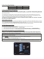
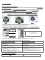
ZENOTEC Air +
Instructions for Use
iVT16-912 (120 volt) & iVT25-912(230 volt)
1- INTRODUCTION
You are now the owner of a Quatro IVac System, an advanced effective indoor air purification system
designed specifically to remove particulate matter. You can expect a noticeable improvement in air quality as
the IVac begins the process of reducing microscopic airborne particulate.
PRINCIPLE OF OPERATION
The iVAC features a four step AUTOMATIC method of operation:
a) rear knockout chamber forces heavier particles to the tray; b) filter captures and holds lighter dust particles; c)
AUTOMATIC CLEANING SYSTEM loosens and releases lighter particles captured in the filter down into tray followed
by a cerified HEPA filter d) heavy duty blower section to overcome static pressure across the hose and filter.
UP/DOWN Arrows on control panel allow you to increase and decrease speed in 10 increments.
Tray beneath the filter can be easily released and unloaded, without manipulating the filter. This allows for easy and
clean debris removal.
UNIT INSPECTION
Upon receipt, inspect unit for either visible or concealed damage. Damage should be immediately reported to the
transport company.
If you suspect concealed damages inside the box indicate so on the transport companies’ shipping
documents.
Bottom drawer of unit contains: a) Power cordset, b) 2”dia. 8 foot hose, c) Communication cable (9-pin),
d) (4) EXTRA motor brushes, e) O&M manual.
Place extra motor brushes & manual in safe place for future use. Motor brushes will wear & must be replaced.
These brushes will provide you with 1 replacement, please order next set after replacing, to avoid urgency.
2- IMPORTANT SAFETY PRECAUTIONS
WARNING- To reduce the risk of severe injury read and follow all instructions
-To reduce the risk of electric shock, do not expose to water or rain. Do not operate the system in
areas with excessive moisture .
-Ensure to use proper voltage as noted on the serial # sticker
-All filters must be in place whenever this machine is in operation.
-Use only on a grounded electrical circuit; do not use any two-wire electrical prong adapters to defeat
the three-pronged plug on the end of the cord.
-Disconnect power prior to accessing unit, when checking or replacing filters, or servicing motor (blower).
-When servicing the motors be careful when touching the exterior of the motor as soon as it has been
turned off; it may be hot enough to be painful or cause injury. With modern motors, this condition is
normal when operated at rated load and voltage, as they are built to operate at higher temperatures.
SAVE THE INSTRUCTION MANUAL FOR FUTURE REFERENCE
Ensuring Proper Grounding of ABS/PVC Fittings and Tubing for a Dust Collection System.
For dust collection systems, galvanized metal pipe and fittings are best, but for most typical applications, fittings and
dust collection tubing made of plastic (ABS or PVC) are sufficient, provided they are properly grounded to dissipate
static electrical charges. Dust and air in the right proportions can be an explosive mixture, and a build up of static
electricity can provide the spark to ignite it.
To safely collect and bleed off the static charge, bare copper wire (not insulated) should be run along the inside of the
duct-work and be attached to grounding screws or a bare metal surface on both the dust collector and the unit that it is
connected to (if it is connected to a unit). The power cords of both machines must be terminated in a grounded threeprong plug to complete the connection to the ground. Wires over the irregularities of fittings, especially at “Y”s or “T”s
could form traps for particles. Therefore, bypass the fittings by running the wires to the outside through small holes.
Seal the holes with silicone caulking compound and join the wires by twisting them together and securing them with a
wire nut.
As charges can also collect on the outside surface, we recommend wrapping bare copper wire in a spiral around the
outside of the ductwork, securing it with electrical tape and connecting it to the ground system by means of wire nuts. If
you have any difficulty securing the hose clamp to the hose and fittings, try wrapping the joints with duct tape first to
provide a good gripping surface. If you are still having difficulty in obtaining a safe electrical ground, we recommend the
services of a good electrician.
.
3- IMPORTANT INSTALLATION INSTRUCTIONS
WARNING – To reduce the risk of fire or injury read and follow all instructions.
-Do not install or operate the system in an enclosed space. Do not block discharge grill. Keep all objects
at least 6” away from the casing. NEVER place the system up against a wall.
-Do not kink hose or restrict airflow in any way.
SAVE THE INSTRUCTION FOR FUTURE REFERENCE
4- IMPORTANT OPERATIONS INSTRUCTIONS
WARNING – To reduce the risk of damage to your system read and follow all
instructions. Failure to follow these guidelines may result in undesired operation or
damage that will not be covered under warranty.
-THE SYSTEM IS DESIGNED TO BE CONSTANTLY POWERED (PLUGGED IN). USE THE ON/OFF
ONLY SWITCH TO TURN THE SYSTEM ON & OFF
-ALWAYS SWITCH THE POWER OFF BEFORE UNPLUGGING THE SYSTEM FROM THE MAIN
POWER SOURCE OR BEFORE CUTTING POWER TO THE RECEPTACLE. FAILURE TO DO SO
MAY CAUSE DAMAGE TO THE SYSTEM THAT IS NOT COVERED UNDER WARRANTY.
-QUATRO IS NOT LIABLE FOR MISAPPLIED EQUIPMENT. ALWAYS CHECK SYSTEM VOLTAGE
BEFORE PLUGGING INTO POWER SOURCE
Warning:
This is a class A product. In domestic environment, this product may cause radio interference in which case the user
may be required to take adequate measures.
5- PRE START-UP CHECKLIST
a) Place the IVac System in the desired area for use.
b) Open bottom access door. Slide out drawer and remove all accessories & manual. Slide drawer back in and
close bottom access door.
c) Open top access door & verify that all the filters are installed properly. Close access door and screw in knob.
d) Connect the supplied hose to Wieland Zenotec Milling Machine
6- START-UP
a) Insert male end of power cord into grounded circuit of the proper voltage and that can handle the system
amperage.
b) Plug in the supplied remote cable to the iVac & the Wieland Zenotec Milling Machine.
c) Start a process on the Zenotech Milling Machine. The iVac will start up by itself when it receives the 24VDC
control signal from the Zenotec milling machine system
d) Adjust fan speed controls to the minimum required airflow. As the filters get dirty the system will automatically
increase speed to keep a constant airflow.
WARNING: DO NOT OPERATE UNIT UNLESS ALL FILTERS ARE IN PLACE.
.
7- i Series Controls
Our “i Series” Controls feature soft touch On/Off, Speed Up & Speed Down Buttons and a remote
operation interface. It also features a visual and audible alarm system for the filters and the
blower motors should service be required. The i-Series controls are equipped with an “Autoflow”
pressure compensation feature. After setting the minimum speed required to properly evacuate
your equipment the controls will automatically increase the motor speed to compensate for the
increased pressure of dirtying filters until maximum speed is reached. As well after a filter change
the system will automatically decrease the speed to the original set point.
Remote Operation
To enable the remote system startup simply ensure that the i-VAC system has the correct voltage
connected to the unit, then connect the 9-pin control cable supplied with the system. Now when
the unit receives a 24 VDC signal from the Zenotec unit the filter system will start automatically.
The IVac System will respond by illuminating LED 1 (System On) & LED 5 (Remote/Standby).
Whenever the remote signal is supplied the unit will instantly start, when the remote signal is
stopped the unit will stop after a 3 second delay.
If applicable set the shut off delay in Zenotec control software to the shortest possible
interval. The iVac System has a 3 second delay that cannot be turned off.
Note: When operating by remote control the use of the On/Off (Power) button on the panel is
disabled while the Remote/Standby light is ON Solid Or Fading In And Out.
If you wish to use the On/Off button on the panel after Remote Operation has been enabled the
function is only available when the Remote/Standby light is flashing slowly (No Remote signal is
present, system is in standby). While in operation via the ON/Off (Power) button, remote
operation is temporarily disabled. Turn the unit off with the ON/Off (Power) button to go back into
Remote Operation.
AUTOMATIC FILTER CLEANING
The system is set from the factory to automatically clean the filter after every hour of operation.
MANUAL FILTER CLEANING
If additional cleaning is required, a MANUAL EXTRA CLEANING FEATURE is included. To
initiate, do the following:
a) Unit must be in operation (“SYSTEM ON” Led illuminated)
b) PRESS & HOLD POWER button for approximately 10 seconds (release button ONLY when
you hear the BEEP)
c) Unit will STOP OPERATING
d) “Remote / Standby “ Led will illuminate, Press POWER
e) EXTRA Cleaning will cycle ON (and clean out dust particles) for 10 seconds, Once cleaning is
completed, unit will then go back to previous position.
Light Diagnostics Table D10-8 & C10-8
Light
Led 1
System
Operation
Illuminated
FULLY
Illuminated
FULLY
Illuminated
FULLY
Low System
Pressure
Flashing
Quickly
Service
Motors
Led 2
Led 3
Led 4
Illuminated
FULLY
Fading
IN-OUT
Flashing
Slowly
Fading
IN-OUT
Fading
IN-OUT
Flashing
Slowly
Flashing
Quickly
Flashing
Quickly
Flashing
Quickly
Service
Filters
Illuminated
FULLY
Flashing
Slowly
Flashing
Quickly
Flashing
Quickly
Illuminated
FULLY
Audible
Alert
None
None
None
None
Condition
Unit is operating using POWER button
on panel, no remote signal
Unit is operating using remote signal
(or mc2 signal if provided)
Shutdown delay
(Remote /mc2 signal has been removed)
Unit is in Standby mode, waiting for
remote signal (or mc2 signal if
provided) to start unit
Beep
Every
Second
Beep
Every 4
Hours
Abnormally Low Pressure, Unit has or
Will Shut Down If Not Corrected
Beep
Every
15 Mins
Beep
Every 5
Mins
Beep
Every
Second
30 hrs of life left in brushes
50 hrs of life left in brushes
Motor Brush Life Expired Unit Shut
Down
Replace ALL motor brushes.
Reset Brush Life Alert
See Video Link:
www.youtube.com/watch?v=LOm81obvaDE
Prepare To Replace/Service Filters
Beep
Every
Hour
Beep
Every
Second
Beep
Every
Hour
Filter Pressure Close To Critical
Flashing
Slowly
None
Flashing
Quickly
Illuminated
FULLY
None
Unit in operation & filters are
scheduled to be cleaned the next time
unit is shut off for more than 5
seconds
Unit is OFF, filter being cleaned
None
Fading
IN-OUT
OFF
None
Fading
Illuminated
None
Using The POWER button while L5 is
Flashing SLOWLY will temporarily
disable any active remote standby.
To Re-Establish STANDBY turn the
unit off using the POWER button.
Check Motor(s), Check Motor Brushes,
Verify If Filters Are Installed,
Close All Filter Access Points
Order brushes if not already on
hand.
If brushes on hand change now and
reset alert.
Unit Will SHUT DOWN In 30 Hours to
prevent motor damage
Unit Will SHUT DOWN In 10 Hours to
prevent motor damage
Filter Pressure High
Fading
IN-OUT
Action
10 hrs of life left in brushes
None
Illuminated
FULLY
Filter Auto Illuminated
Clean
FULLY
(iVac Only)
Led 5
Critical Pressure, Unit Shut Down
Replace Filter (s) ASAP
Unit in operation.
ALERT, filter cleaning motor not
operating at optimum
Unit is in Constant AUTO Cleaning Mode
Vacuum Controlled By POWER Button On
Control Panel
Unit is in Constant AUTO Cleaning Mode
Replace/Service Filters Now.
Continued Operation Will Result In
Unit Shutdown
Verify Blockage, Verify All Filters
Replace Filter (s) ASAP
Reset Filter Life Alert
See Video Link:
www.youtube.com/watch?v=LOm81obvaDE
Replace Filter Cleaning motor
Unit Automatically Shuts OFF
Vaccum , Cleans & The ReStarts
Vaccum
Unit Automatically Shuts OFF
.
IN-OUT
FULLY
Vacuum Controlled By Remote or mc2
Vaccum , Cleans & The ReStarts
Vaccum
8- IVac i Series Specifications
Description
Approximate Dimensions:
Voltage, current
Approx. Weight:
iVT16-912
29”h x 16”w x 20”d
120/1/60, 12.8 amps
85lbs
iVT25-912
29”h x 16”w x 20”d
230/1/50,8 amps
85lbs
9- General Maintainence & Inspection
Proper maintenance is critical to extend the life of the filtration system. The information presented below outlines basic
maintenance procedures ensuring the unit will provide trouble-free operation for years to come. The purifier is designed to allow
quick access to the filter.
The “Replacement Indication System” monitors system pressure and tells you when the particulate filter need servicing.
If a critical pressure is reached the unit will shut down to prevent damage. This will occur even if your equipment is in mid
process. It is advised to service/change the filter when prompted or ASAP to avoid a shutdown.
JUST BECAUSE THE SERVICE FILTERS LED IS NOT ILLUMINATED DOES NOT MEAN THAT THE DUST TRAY DOES
NOT NEED TO BE SERVICED/EMPTIED.
ANNUAL GENERAL INSPECTION
Sealing integrity of iVAC is essential. Every 12 months, verify all gaskets are in proper condition. Should the door gaskets adhere slightly to the unit when
opening a door, lubricate its surface with a transparent grease or petroleum jelly. Should unit be moved on occasion, ensure that rubber grommets are tightly
fastened. Disconnect the unit by unplugging the power cord from the wall, and access the fan section. Verify that the acoustic insulation
is well fastened to the walls. In the event of a problem, call your authorised distributor for spare parts and replace immediately.
10- Filter Replacement Guide
Filter requires replacement if appropriate light on control panel illuminates (and beeper sounds for 2 seconds every 4 hours).
Filter replacement is ALSO required if you notice the following:
a)
If you are losing suction capacity, after filter has been used…..FILTER IS CLOGGED;
b)
If dust is coming through the filter and dust is present in the motor section even though filter is seated properly……..FILTER IS PUNCTURED;
c)
Gasket on BASE of filter is even slightly worn….GASKET NEEDS TO BE IN GOOD CONDITION TO ENSURE DUST DOES NOT GET THROUGH
RESETTING MICROPROCESSOR AFTER FILTER HAS BEEN REPLACED
Whether your Led is illuminated or not, RESETTING the Microprocessor is essential, as it provides microprocessor with true
information. A Clean Filter has a much lower pressure, if you do not RESET, it may interpret lower pressure readings as a low
pressure warning & a signal of other type of imminent failure.
AFTER REPLACING THE FILTER:
• Plug power back to the unit
• Press Power ON (so unit motor is operating)
• HOLD SPD UP & DN ARROWS (at the same time) until microcontroller BEEPS continuously
• Once panel BEEPS, “System ON” light will flash quickly & lights below will be FLASHING or Dimming in-out:
• using UP/DN arrows, Press UP or DN until “Service Filter(s)” light is FLASHING
• Press and HOLD POWER button, “Service Filter(s) light will go OFF
• light will STOP flashing, filter is now reset and unit is operational again after 20 seconds
NOTE: if at any time you are in RESET MODE and wish to leave without pressing any buttons or resetting any Alarm Lights, simply do not touch the
panel for 20 seconds and unit will go back to Operational Mode
(Microprocessor will keep in memory any RESET that you have pressed)
.
11- MOTOR SERVICE
BLOWER MAINTENANCE, CHANGING BRUSHES
This unit is also equipped with an Automatic Motor and Brush Optimization System. To optimize motor life, motor brushes need to be monitored and replaced
PRIOR TO BEING WORN RIGHT OWN TO THE BASE. If brush is worn to the base, there is HIGH RISK of brush damaging the motor. If this happens, you will
require replacement of entire motor.
To avoid this, QUATRO has developed an Automatic Motor and Brush Optimization System. When “Service Motors” light FLASHES continuously, it is time
replace brushes (wear factor is down to 10-20% life remaining). As soon as “Service Motors” light starts flashing continuously order new brushes right away.
When Automatic Motor and Brush Optimization System estimates motor brushes have been worn to dangerous level, UNIT WILL SHUT DOWN.
BRUSHES MUST BE REPLACED AT THIS POINT, UNIT WILL NOT OPERATE FOR FEAR OF MOTOR DAMAGE.
To optimize and ensure longest brush life, AFTER REPLACEMENT, START motor right away, speed will automatically default to LOW.
Operating the motor at Low speed for 15 minutes will “break-in” the new brushes, optimizing and prolong their life.
WARNING: Switch unit off and unplug power cord from wall before servicing the blower.
Figure 1
Figure 2
Figure 3
1) Using a phillips screwdriver, unscrew the 2 screws holding down each of 2 gold colored brush casings (see Figure 1)
2) Lift gold colored tab and lift/pull out each brush (Figure 2 shows right brush removed)
3) Replace each brush onto turbine motor, screwing down the phillips screws over tab.
YOU DO NOT HAVE TO REMOVE TURBINE FROM UNIT TO CHANGE BRUSHES!
Motor(s) located in the
rear of unit
Main Filter Section
Motor(s) located in the rear of unit
iVAC models have 1 motor
iVAC TWIN models have 2 motors
Dust Collection
Chamber
To access motor, remove blower section door. TURBINE & BRUSHES are visible once door is removed.
RESETTING MICROPROCESSOR CONTROLLER AFTER REPLACING MOTOR BRUSHES
If Motor Brushes are replaced
WHILE BRUSH REPLACEMENT LIGHT was FLASHING
•
•
•
•
•
•
•
•
•
•
•
Unplug POWER to unit
Replace Motor Brushes
Close motor access door
Plug power back to the unit
When you Press “System ON”, MOTOR WILL START
BUT “Service Motor(s) Light will continue flashing
Press & HOLD SPD UP & DN at the same time until unit BEEPS (5 seconds)
“Service Motor(s)”, “Service Filter(s)” & “AutoCleaning Filter” Lights will be Dimming
In-Out or flashing
Press SPD UP or DN until “Service Motor(s)” light is FLASHING
Press and HOLD POWER button, “Service Motor” light will go OFF
DO NOT PRESS ANY OTHER BUTTON, after 20 seconds, speed will default to
LOW SPEED to break new brushes in (to prolong brush life)
IT IS ADVISED TO LET MOTOR OPERATE AT LOW SPEED FOR 15 MINUTES
If Motor Brushes are replaced
AFTER MICROPROCESSOR HAS SHUT UNIT DOWN
(Brush Replacement Light is FULL ON, not flashing)
• Unplug POWER to unit
• Replace Motor Brushes
• Close motor access door
• Plug power back to the unit
• When you Press “POWER ON”, MOTOR WILL NOT START
BUT “Service Motor(s) Light will continue flashing
• Press & HOLD SPD UP & DN at the same time until unit BEEPS (5 seconds)
• “Service Motor(s)” Light will be FLASHING, & “Service Filter(s)” & “AutoCleaning Filter”
Lights will Dim In-Out
• Press & HOLD POWER button, “Service Motor” light will go OFF
• DO NOT PRESS ANY OTHER BUTTON, after 20 seconds, speed will default to LOW
SPEED to break new brushes in (to prolong brush life)
IT IS ADVISED TO LET MOTOR OPERATE AT LOW SPEED FOR 15 MINUTES
12- TROUBLESHOOTING GUIDE
Symptoms
Possible Cause
Suggested Solution
.
Unit Will Not Start
Unit Starts,Then Stops
Excessive noise
Faulty Power Supply
Control Panel Circuit Breaker Tripped
Unit Not Plugged Into Receptacle
Excessive Pressure
Hose Blocked
Particulate Filter Blocked
Filter Not Installed
Check Breaker Box
Reset Circuit Breaker
Plug Unit In
Change filters, look for system blockage
Remove Obstruction
Check For Proper Installation Of Filters
Install Filters
Motor Bearing Failure
Rubber Motor Isolators Broken
Replace Motor
Replace Isolator
13- WARRANTY
QUATRO Air Technologies warrants its equipment to be free from defect in material and workmanship under normal use and
service for a period of one year from date of shipment. QUATRO's obligation under this warranty shall be limited to
replacing any parts, thereof, which shall be demonstrated to have been defective. This is expressly in lieu of all other
warranties, express or implied, including the warranties of merchantability and fitness.
QUATRO claims no warranty as to merchantability or as to the fitness of the merchandise for any particular use and shall not
be liable for any loss or damage. No person, firm or corporation is authorised to assume for QUATRO any other liability in
connection with the sale of these goods. Equipment, parts and material manufactured by others and incorporated in
QUATRO's equipment are warranted by QUATRO only to the extent of the original manufacturer's liability to QUATRO Air
Technologies Inc.
Conditions and Limitations:
This warranty does not cover abuse, misuse, maintenance negligence, improper assembly, acts of vandalism, acts of God,
fear wear, modifications of the equipment or installation of a part not recommended by QUATRO Air Technologies, as well as
operation of the equipment at voltages other than those specified by QUATRO Air Technologies Inc.
14- iVacTwin REPLACMENT FILTER & PARTS
Qty
1
1
1
1
1
1
1
1
1
Description
Blower Motor Assy 120v
Blower Motor Assy 230v
Motor Brush Kit
Power Cord 120v
Power Cord (Euro 230V)
Filter Cartridge
Hepa Filter
Filter Cleaning Motor 120V
Filter Cleaning Motor 230V
Part
75-22-0813
75-22-0814
75-22-0815
75-22-0816
75-22-0817
75-22-0818
75-22-0819
75-22-0820
75-22-0821
EXPECT THE DIFFERENCE! BY WIELAND.
As a major supplier of dental system solutions, WIELAND embodies both tradition and progress
in matters of dental products and technology. Since our company was founded in 1871, we have
stayed true to our corporate philosophy of combining tradition, innovation and quality with the
best in customer care. Today, our core competencies and key strengths lie in the forward-looking
integration of technologies and materials for dental prosthetics. This ensures that patients can
trust in the quality of their dentures, and our partners in dental practices and laboratories can
continue with confidence on the path to digitalisation and greater competitiveness.
www.wieland-international.com
WIELAND Dental + Technik GmbH & Co. KG
Schwenninger Straße 13, 75179 Pforzheim, Germany
Fon +49 72 31 / 37 05 - 0, Fax +49 72 31 / 35 79 59
535089e.01.12/10
WIELAND offers a wide range of products and services from CAD / CAM technologies and
dental alloys to veneering ceramics and electroforming. Thanks to our worldwide presence
and international network, WIELAND is never far away, and your contact person can always
be located via the Internet.