1
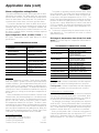
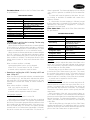
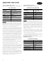
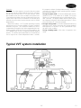
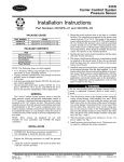
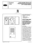
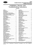
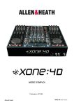
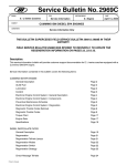
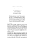
Product
Data
33CS
Carrier Comfort System
Variable Volume and
Temperature (VVTT)
The VVT Comfort System provides
the following features and benefits:
• 365-day scheduling, daylight savings
compensation, and 8 daily program
periods
• Quick and easy start-up wiring
• System control capability
• New adjustable alarm limit capability
• An Indoor Air Quality (IAQ) high
limit CO2 sensor is available
• Enhanced equipment coordination
Features/Benefits
The newest generation of
VVT System products
combines the industry leading VVT System technology
with the direct digital controls of the Carrier Comfort
Network. The VVT Comfort System provides an
effective balance between
flexible zone comfort, diverse system application
requirements, and efficient
high-performance unit
operation.
Scheduling flexibility for every
application
An electronic timeclock provides
365-day scheduling of 8 occupied
and unoccupied time periods. A
10-hour, non-battery clock backup
during power outages protects your
configurations and schedules. Multiple
clocks can be used on the same
network.
Copyright 1997 Carrier Corporation
Form VVT-1PD
Holiday scheduling for up to 18
holiday schedules with multiple days
per schedule allows flexibility and
adaptability to the needs of each application. Daylight savings and leap
year scheduling is also included.
External timeclock control can be
used with the VVTt Comfort System thermostat to allow an external
clock control of the occupied and
unoccupied schedules.
Network occupancy control allows
the VVT Comfort System thermostat to use its own occupancy
schedule, or to follow the schedule
of a network device. Schedules can
be used by many different devices
for ease of programming and
serviceability.
Control flexibility
Occupant control of set points
allows the VVT Comfort System to
satisfy all user comfort levels. Individually adjustable heating and cooling
set points maximize occupant comfort
for every scheduling requirement.
Unoccupied override allows the occupant to extend or return to the
occupied set points by overriding the
unoccupied schedule. The occupied
schedule can be extended for 1 to
4 hours after the unoccupied scheduled start time.
Temperature and time schedule
access is provided to suit the level of
comfort of every occupant.
Raised interface buttons improve
the look and feel of the interface
which make configuration changes
effortless.
Rotating display option provides
two different information displays to
suit the needs of the user. Set points
or zone temperature and set points
can be displayed.
Wide scope of capabilities for
all building requirements
IAQ (indoor air quality) sensor
continuously monitors space or system
air quality (CO2) and adjusts outdoor
air intake as needed. An alarm is generated if the IAQ level exceeds the
user-configured limits.
Pre-occupancy purge provides a
‘‘flushing’’ of the building one hour
previous to the scheduled occupancy
time.
Remote room sensor averaging
improves the total comfort of the
2
conditioned space. When large zones
exist with hot or cold spots, a total
of 4 remote room sensor readings
can be averaged.
Demand limiting integrates the
energy management functions of the
Loadshed module into the system
to optimize participation.
Tenant metering offers an easy way
to collect 3 different types of usage
data. The amount of time that zone
demand matches system mode, the
amount of time that zone demand
matches system mode during unoccupied override, and the amount of
time that unoccupied override is active
can be collected by tenant metering.
The zone controller can collect the
amount of time that supplemental
heat is used.
Supplemental heat provides supplemental or zone heat independent of
the central HVAC unit. Supplemental
heat can be disabled when the outside air rises above a user-configured
lockout set point.
System performance is
optimized
System heating and cooling mode
lockout maximize the effectiveness
of system heating and cooling requirements by disabling heating or cooling operation when the outside air
temperature exceeds the configurable
lockout set point.
Optimal start brings the conditioned
space to within occupied set points
prior to the occupied time period to
ensure occupant comfort.
Optimized staging maximizes first
stage heating or cooling performance
by suspending second stage operation when the first stage continues to
meet space temperature requirements.
Economizer operation optimizes
the use of outside air for cooling.
When the outside air temperature is
suitable for cooling, the economizer
operates to condition the space, maintaining performance while reducing
the system requirement for mechanical cooling.
Reliable equipment operation
maximizes unit dependability
System mode demand establishes
the minimum number of zones that
require heating/cooling before a system heating or cooling mode is selected. This unique sequence prevents
the cycling of equipment attempting
to meet troublesome requirements
of a single zone.
High- and low-temperature limit
protection ensures the supply-air
temperature is maintained within
a configurable unit-specific range.
When acceptable temperatures cannot
be maintained, heating and cooling
stages will be shut off to ensure safe
and proper operation of the
equipment. This avoids having to reset
the HVAC unit.
Table of contents
Page
Features/Benefits . . . . . . . . . . . . . . . . . . . . . . . . . . . . . . . . . . . . . . . . . . . . . . . . . 1-3
Model Number Nomenclature . . . . . . . . . . . . . . . . . . . . . . . . . . . . . . . . . . . . . . 3
Accessories . . . . . . . . . . . . . . . . . . . . . . . . . . . . . . . . . . . . . . . . . . . . . . . . . . . . . . 4
Base Unit Dimensions . . . . . . . . . . . . . . . . . . . . . . . . . . . . . . . . . . . . . . . . . . . . . 5
Accessory Dimensions . . . . . . . . . . . . . . . . . . . . . . . . . . . . . . . . . . . . . . . . . . . . . 6,7
Component Selection Procedure . . . . . . . . . . . . . . . . . . . . . . . . . . . . . . . . . . . . 8
Performance Data . . . . . . . . . . . . . . . . . . . . . . . . . . . . . . . . . . . . . . . . . . . . . . . 9-11
Application Data . . . . . . . . . . . . . . . . . . . . . . . . . . . . . . . . . . . . . . . . . . . . . . . . 12-19
Typical VVT System Installation . . . . . . . . . . . . . . . . . . . . . . . . . . . . . . . . . . . . 19
Guide Specifications . . . . . . . . . . . . . . . . . . . . . . . . . . . . . . . . . . . . . . . . . . . . . 20-23
Features/Benefits (cont)
Leaving-air temperature (LAT)
algorithm monitors the leaving- air
temperature to ensure safe and proper
operation of the HVAC equipment.
The LAT is constantly monitored and
system adjustments are made to
maintain LAT requirements.
Time Guardt compressor protection prevents excessive equipment
cycling by requiring a minimum down
time after a heating or cooling cycle
and a minimum heating and cooling run time.
Staggered unit starting times of
multiple units upon power failure and
at the start of occupied times reduces unnecessary electrical demand
loads. The unique addressing of
thermostats automatically provides
this capability without additional configuration requirements.
Serviceability and troubleshooting
Advanced diagnostics are built-in to
the VVTt Comfort System and constantly verify proper system operation
and provide information to speed
system troubleshooting.
Fan and filter status allows service
needs to be pinpointed.
Heating and cooling mode error
set points continuously monitor
the supply-air temperatures. If the
supply-air temperatures exceed the
configurable error set points, then
an operating error is generated to
inform the service personnel of the
condition.
Error code display on each thermostat provides a quick diagnosis of
system operating status.
Space comfort trending eases
troubleshooting. If space comfort temperature trends indicate a loss of
comfort conditions, a comfort trend
error is generated. The comfort trend
error alerts the servicing contractor
to provide quick resolution.
Self-health test is performed by the
system to ensure proper system operation and performance.
Simplified installation and
configuration
Multiple configuration access levels of security protect system configurations while providing occupant
access to space temperature and
operating schedules.
Easily accessible function menus
make system setup and configuration intuitive, even for first time users.
System displays present the data in
a clear easy to read format, with
all data grouped in logical categories.
Start-up configuration category
contains essential start-up configuration options for a quick system
setup. Typical default values are assigned to minimize start-up and
configuration time.
Full system configuration is done
at the thermostat. No additional
computer or start-up configuration
tools are required to complete system
installation.
Model number nomenclature
3
Accessories
Outdoor-air sensor — The outdoor-air sensor reads temNetwork access module — Allows network access via
peratures between 0 and 150 F and is used to report the
computer at the site or remotely through the use of a mooutdoor-air temperature to the communication bus. The indem. The Carrier Network Access software can modify and
formation can be used to lockout heating or cooling modes
read information of devices residing on the network.
when the temperature is not within user configured limits.
→ Fan status switch — The fan status switch senses the
The outdoor-air sensor is needed when an economizer is
condition of the unit indoor fan (ON/OFF).
used.
→ Filter status switch — The filter status switch senses the
Humidity sensor — The humidity sensor is used to read
condition of the unit filter (CLEAN/DIRTY).
the indoor relative humidity (between 10 and 90%) and
Indoor air quality (IAQ) sensor (CO2) — The indoor
broadcast the information to the communication bus.
air quality sensor measures the amount of CO2 present in
Static pressure pickup — The static pressure pickup is
the air in ppm. The amount of outside air being sent to the
used to modulate the bypass damper. It is used in pressure
space is increased if the reading is above the configured set
dependent applications.
point. Three types of IAQ sensors are available: duct mount,
Velocity pickup — The velocity pickup is used to meawall mount, and wall mount with LED display.
sure the air velocity entering a zone for use in pressure inIAQ sensor calibration service kit — The IAQ sensor
dependent applications. The information is used to moducalibration kit contains everything needed to calibrate the
late the zone damper. The velocity pickup is available in 12,
IAQ sensor. The kit contains: IAQ Sensor Software Cali18, and 26-in. lengths to fit every application.
bration software, computer connection cable, calibration
Pressure sensor — The pressure sensor is used to read
blanket, bottle of N2 gas, bottle of CO2 gas, pressure reguthe duct or zone pressures. The information is used to modulator, tubes, and clips.
late the zone or bypass dampers. The pressure sensor is
IAQ sensor software interface program — The IAQ
available for 0.5 and 2.0 in. wg applications.
sensor is factory-set for an alarm at 1000 ppm of CO2.
The setting can only be changed through the use of the IAQ
Round damper actuators — Round damper actuators
sensor software interface program. The accessory also
are available in 6, 8, 10, 12, 14, and 16-in. sizes. Conneccomes with a computer connection cable and an operation
tions are provided for sensors and monitor thermostat or
manual.
zone controller wiring.
VVTt system relay packs — The CHR-03, CHR-06,
Rectangular damper actuators — Rectangular damper
CHR-06W, and HR-03 relay packs are used to connect the
actuators are available in 8 x 10, 8 x 14, 8 x 18, and
VVT Comfort System thermostat to the HVAC unit. Relay
8 x 24 in. sizes. Connections are provided for sensors and
packs are available as a factory-installed option or a fieldmonitor thermostat or zone controller wiring.
installed accessory.
→ High torque actuators — High torque actuators are availFor Monitor-Only mode operation, 33CSUCE-06 and
able for applications with larger static pressures. High torque
TSR-01 relay packs are used. The 33CSUCE-06 relay pack
actuators provide higher torque and degrees of rotation.
is outdoor duty rated.
Pressure sensor wiring harness — The pressure senRemote duct sensor (RDS) — The RDS is mounted in
sor wiring harness allows a pressure sensor and an IAQ
the supply air duct and is used to sense duct temperatures
sensor to be wired directly to a damper actuator. The presbetween 30 and 180 F. The RDS is used for equipment
sure sensor harness is standard with the bypass actuator.
protection.
Multi-sensor wiring harness — The multi-sensor wiring
Remote room sensor — The remote room sensor is used
harness allows the airflow sensor and filter sensor to be wired
to report space temperature from a space at locations other
to the monitor thermostat damper actuator.
than or in addition to where the thermostat is located. Up
Help screens for network access software — A disk
to 4 Remote Room Sensor readings can be reported to one
of help screens give the user on-line information about the
thermostat and averaged.
monitor thermostat, zone controller, and bypass controller.
4
397
Base unit dimensions
VVTt MONITOR THERMOSTAT WITH TIMECLOCK
7-1/16″
7/8″
2″
1-1/2″
3-7/8″
1-5/8″
3/4″
FRONT VIEW
SIDE VIEW
VVT MONITOR THERMOSTAT WITHOUT TIMECLOCK, OR ZONE CONTROLLER,
BYPASS CONTROLLER
5-3/8″
7/8″
2″
1-1/2″
3-7/8″
1-5/8″
3/4″
FRONT VIEW
SIDE VIEW
5
Accessory dimensions
MODEL RD — RECTANGULAR ZONE DAMPER ACTUATOR
DIMENSIONS (in.)
MODEL
RD0810
RD0814
RD0818
RD0824
A
101⁄4
101⁄4
101⁄4
101⁄4
B
17
21
25
31
C
8
8
8
8
D
10
14
18
24
MODEL ZD — ROUND ZONE DAMPER ACTUATOR
DIMENSIONS (in.)
MODEL
ZD-06
ZD-08
ZD-10
ZD-12
ZD-14
ZD-16
6
A
6
8
10
12
14
16
B
18
18
18
24
24
24
C
11
13
15
17
19
21
E
131⁄2
131⁄2
131⁄2
131⁄2
→ UNIT CONTROL RELAY PACKS
(Monitor-Only Mode Applications)
MODEL TSR-01 MOUNTED IN
RE (REMOTE ENCLOSURE)
WITH REVERSING VALVE
CONTROL AND INDOOR DUTY RATED
MODEL 33CS UCE-06 MOUNTED IN
RE (REMOTE ENCLOSURE)
WITH ECONOMIZER CONTROL
AND OUTDOOR DUTY RATED
UNIT CONTROL RELAY PACKS
(VVT® Monitor Mode Applications)
MODEL CHR-06W WITH ECONOMIZER CONTROL AND INDOOR DUTY RATED
DIMENSIONS (in.)
MODEL
CHR-06W
A
43⁄4
B
3
MODEL CHR-06 WITH REVERSING VALVE CONTROL AND INDOOR DUTY RATED
DIMENSIONS (in.)
MODEL
CHR-06
7
397
A
43⁄4
B
3
Component selection procedure
Proper selection of the monitor thermostat is important
to meet job requirements. Selection of the monitor thermostat and other components is based on the following
criteria:
I Zone Capacity
Monitor thermostats are available in 3 capacities: 4,
16, or 32 zones. A system with 4 zones would require an 33CSVM(T)-04 monitor thermostat which
would control one zone and 3 zone controllers
(33CSZC--01) for the remaining zones. A 20-zone
system would require a 33CSVM(T)-32 monitor thermostat and 19 zone controllers.
II Timeclock
Monitor thermostats are available in timeclock and
non-timeclock versions. Select the monitor thermostat
with timeclock when that monitor thermostat will be
the device broadcasting time to the other devices on
the network. A ‘‘T’’ in the 7th digit of the model number indicates a timeclock (i.e., 33CSVMT-04). A dash
indicates no timeclock (i.e., 33CSVM--04).
III Mode
Monitor thermostats can be used in 2 modes: VVTt
Monitor mode and Monitor-Only mode. In VVT Monitor mode, the monitor thermostat controls its own
damper. An 8-zone system would have one monitor thermostat (in VVT Monitor mode) and 7-zone
controllers. In Monitor-Only mode, the monitor thermostat does not control a zone damper. An 8-zone
monitor-only system would have one monitor thermostat (in Monitor-Only mode) and 8-zone controllers.
8
→ IV Relay Pack
Relay pack selection is based on operating environment and application. A Monitor-Only mode application can use either a TSR-01 or 33CSUCE-06 relay
pack. Select the TSR-01 relay pack for indoor mounting environments. Select the 33CSUCE-06 for outdoor duty environments. It is also used in units having
a W-973 controller. Both relay pack models offer 2-stage
heat and cool and ON/OFF fan control.
For VVT Monitor mode applications, select the CHR-06
or CHR-06W relay pack. Both are for indoor mounting environments. They are also used in units having a
W-973 controller. Both relay pack models offer 2-stage
heat and cool and ON/OFF fan control.
397
Performance data
APPLICATION NC* LEVELS (RADIATED SOUND) — ROUND ZONE DAMPERS
DAMPER
CFM
160
200
ZD-06
240
360
280
350
ZD-08
420
630
440
514
ZD-10
584
659
990
630
700
770
ZD-12
860
950
1425
STATIC PRESSURE
(in. wg)
0.02
0.52
1.00
0.04
0.50
1.00
0.06
0.50
1.00
0.10
0.50
1.00
0.03
0.50
1.00
0.04
0.50
1.00
0.06
0.50
1.00
0.10
0.50
1.00
0.01
0.50
1.00
0.02
0.50
1.00
0.03
0.50
1.00
0.04
0.50
1.00
0.09
0.50
1.00
0.01
0.50
1.00
0.03
0.50
1.00
0.02
0.50
1.00
0.04
0.50
1.00
0.05
0.50
1.00
0.11
0.50
1.00
NC LEVEL
<20
<20
25
<20
22
24
<20
24
28
28
32
35
<20
<20
22
<20
22
22
28
25
27
28
28
30
22
25
27
22
28
29
25
27
32
30
32
34
35
35
37
22
35
38
22
37
38
22
38
39
27
39
40
32
40
40
40
44
45
*Noise Criteria.
NOTE: The NC values are based on ARI (Air Conditioning and Refrigeration Institute) Standard 885-90
application assumptions.
9
Performance data (cont)
APPLICATION NC* LEVELS (RADIATED SOUND) — ROUND ZONE DAMPERS (cont)
DAMPER
CFM
852
976
1074
ZD-14
1175
1275
1910
1125
1175
1275
1376
ZD-16
1475
1574
1676
2512
STATIC PRESSURE
(in. wg)
0.02
0.50
1.00
0.01
0.50
1.00
0.01
0.50
1.00
0.01
0.50
1.00
0.06
0.50
1.00
0.13
0.50
1.00
0.02
0.50
1.00
0.04
0.50
1.00
0.05
0.50
1.00
0.05
0.50
1.00
0.06
0.50
1.00
0.07
0.50
1.00
0.03
0.50
1.00
0.18
0.50
1.00
*Noise Criteria.
NOTE: The NC values are based on ARI (Air Conditioning and Refrigeration Institute) Standard 885-90
application assumptions.
10
NC LEVEL
22
30
35
25
32
36
30
32
27
31
35
38
30
36
39
41
45
47
27
39
41
30
39
41
31
40
42
35
41
44
35
42
45
36
44
46
38
45
46
50
51
54
APPLICATION NC* LEVELS (RADIATED SOUND) — RECTANGULAR ZONE DAMPERS
DAMPER
CFM
410
509
RD0810
610
914
561
625
RD0814
725
825
1237
725
775
874
RD0818
974
1075
1611
925
974
1075
RD0824
1175
1275
1375
2062
STATIC PRESSURE
(in. wg)
0.01
0.50
1.00
0.03
0.50
1.00
0.07
0.50
1.00
0.16
0.50
1.00
0.02
0.50
1.00
0.02
0.50
1.00
0.03
0.50
1.00
0.05
0.50
1.00
0.11
0.50
1.00
0.01
0.50
1.00
0.01
0.50
1.00
0.02
0.50
1.00
0.02
0.50
1.00
0.03
0.50
1.00
0.06
0.50
1.00
0.01
0.50
1.00
0.01
0.50
1.00
0.01
0.50
1.00
0.02
0.50
1.00
0.02
0.50
1.00
0.03
0.50
1.00
0.06
0.50
1.00
NC LEVEL
<20
30
45
<20
30
40
23
31
40
35
37
45
<20
36
47
22
37
45
25
38
45
32
40
46
40
45
54
22
38
48
22
38
48
28
40
48
30
42
48
33
44
50
40
50
60
26
38
48
27
38
50
32
40
50
35
41
50
37
43
50
38
44
50
47
50
55
*Noise Criteria.
NOTE: The NC values are based on ARI (Air Conditioning and Refrigeration Institute) Standard 885-90
application assumptions.
11
Application data
main bus) has a bus/element address of 0,75, the thermostats on the bridge would have a bus address of 75. Branches
may be added to separate various systems or to reduce the
communication traffic on the main bus.
The VVT system monitor thermostats are available in
3 different zone capacity models which allow it to communicate with 4, 16, or 32 system components. When
addressing the zone controllers, it is not necessary to have
sequentially addressed zone controllers physically next to
each other. Within a VVT system, the monitor thermostat
must have the highest address. The bypass controller and
zone controllers are addressed sequentially below that.
Supplemental heat
Supplemental heat is used to provide control of zone duct
or perimeter baseboard heat. It can either augment the heat
of the central unit or be the primary source of heat. Supplemental heat can only be controlled by a zone controller.
The staging of the heating mode is dependent on the
type of supplemental heat.
→ Parallel fan box — With 1.0° F demand, the fan is energized. With 2.0° F demand, the first stage of heat is energized. With 2.5° F demand, the second stage of heat is
energized.
Series fan box — The fan runs continuously during occupied mode. With 1.5° F demand, the first stage of heat is
energized. With 2.0° F demand, the second stage of heat is
energized.
Baseboard — The fan is not used. With 1.5° F demand,
the first stage of heat is energized. With 2.0° F demand,
the second stage of heat is energized.
Duct mounted heat — With 1.5° F demand, the first stage
of heat is energized. With 2.0° F demand, the second stage
of heat is energized. Fan use requires a system fan. The
zone controller requests the monitor thermostat to turn on
the system fan. If the VVTt system is hydronic, the first
stage is energized 30 seconds prior to the request for system fan.
During supplemental heat, the zone controller will work
to maintain the zone set points. During supplemental heat
mode requiring the system fan (duct mounted heat), the zone
controller maintains the damper at the configured Supplemental Heat Damper Position. If using a series fan box,
parallel fan box, or baseboard heat, the damper is maintained at the minimum damper position.
Selection of damper sizes
All zone dampers (round and rectangular), are equipped with:
supply air temperature sensors, a plug-in wiring header for
the relay pack, a plug-in wiring header for available sensors
(humidity, temperature, pressure, or CO2).
Based on required airflow to the zone, round dampers
are available in 6 sizes to provide optimum airflow for low
pressure applications (1.0 in. wg). Round dampers should
be selected based on the cfm (nominal and maximum) shown
in the table below.
ROUND DAMPER SIZES
Communications
SIZE
(diam. in.)
ZD-06
ZD-08
ZD-10
ZD-12
ZD-14
ZD-16
6
8
10
12
14
16
ZONE CFM
Nominal
Maximum
(800 fpm)
(1200 fpm)
160
240
280
420
440
660
630
950
850
1275
1125
1675
Rectangular dampers should be selected based on the cfm
(nominal and maximum) shown in the table below.
The Carrier Comfort system is a communicating system of
zone controlling thermostats. Through communications, information is shared between zones, which optimizes the use
of the HVAC equipment. Communications also permit the
installer and owner to view and monitor the overall operation of the system.
Communications take place over a 3-wire shielded cable
which is wired to the thermostat connector block. The wiring must be made in daisy chain fashion from one thermostat to another.
Once the communication cable has been installed and the
thermostats have been connected to the cable through the
connector blocks, it is necessary to give the thermostat a
unique identity on the communication bus. This is accomplished through the device address. The device address has
two parts: the element address (specific to the device) and
the bus address (the branch of the communication bus the
device is on). If only one continuous link of devices exists,
the bus address would be 0.
It is possible to break the system into several branches or
subsystems. These branches would be called secondary buses.
A bridge is needed to create a secondary bus. To correctly
address the devices under the bridge, all thermostats must
have a bus address which is identical to the element address
of the bridge. For example, if the bridge (which is on the
12
MODEL
RECTANGULAR DAMPER SIZES
MODEL
RD0810
RD0814
RD0818
RD0824
SIZE
(H x W in.)
8
8
8
8
x
x
x
x
10
14
18
24
ZONE CFM
Nominal
Maximum
(800 fpm)
(1200 fpm)
410
610
560
825
725
1075
925
1375
For applications requiring 2 or more dampers working together to provide the required total airflow, the dampers
have the capability of being wired together. If space restrictions do not allow the use of a 14-in. damper, two 10-in.
round dampers could be wired together to provide the required airflow. In these situations, only one monitor thermostat or zone controller is needed to provide control. It is
wired (5-wire cable) to one of the 2 dampers which is designated the master damper. Wiring from the master damper
to the additional (slave) dampers is accomplished using 3-wire
cable. The master damper is sequenced from the monitor
thermostat or zone controller while the slave damper(s) modulate based upon the movement of the master damper.
397
Damper positions
The dampers provide for full-blade modulation from fullyclosed to fully-open. This is designated as position 0 to position 15. Because individual zone requirements differ from
one building to another, the system has been equipped to
provide minimum and maximum damper positions. Maximum damper position changes the fully-open damper position to a maximum damper position which can be less
than or equal to the maximum (which is 15). Minimum
damper position changes the fully-closed damper position
to a minimum damper position which can be more than or
equal to the minimum (which is 0).
The range of the maximum damper position is from 8 to
15, in increments of 1. The flexibility of the maximum
damper position allows airflow requirements through the
damper to be fine-tuned to best satisfy the space. When
space use changes, airflow can be readjusted to suit the requirements of the new space configuration.
→
The range of the minimum damper position is from 0 to
7, in increments of 1. The adjustment capability allows finetuning of airflow into the space. Minimum circulation levels
can be provided to ensure space comfort.
A ventilation damper position and a supplemental heat
damper position are also used. Refer to the Indoor Air Quality and Supplemental Heat application sections for more
information. Refer to the Radiated Sound performance tables
for damper sound information.
Indoor air quality
The IAQ (indoor air quality) feature allows the Carrier Comfort system to interface with the economizer on the HVAC
equipment and maintain the quality of indoor air within
acceptable limits. An IAQ sensor (CO2) is used to monitor
the IAQ levels in the zone or the return air duct. The monitor thermostat controls the system fan and economizer during an IAQ mode.
The IAQ feature can be defined as system or local IAQ.
Local zone IAQ consists of a zone controller with an IAQ
sensor. When the IAQ alarm is tripped in local mode, only
the zone damper of the zone controller enters IAQ mode.
For local IAQ, the monitor thermostat scans the bus to
→
gather information and monitors the status of the zone controllers. When a zone controller gives the monitor thermostat a local IAQ alarm (zone controller with local IAQ
sensor), the monitor thermostat turns on the system fan (if
in occupied mode). If the IAQ economizer delay is satisfied
and a zone still has a local IAQ alarm, the monitor thermostat checks the outdoor air against the humidity and temperature lockouts. If the IAQ lockout functions are not
tripped, the economizer relay is energized to bring fresh air
into the zone. When the zone IAQ is satisfied or the reset
temperature is reached, the monitor thermostat will deenergize the economizer relay. The system fan will return to its
normal operating mode.
System IAQ consists of a VVTt system with a bypass
controller having an IAQ sensor or a monitor thermostat in
monitor-only mode having an IAQ sensor. A monitor thermostat in VVT monitor applications has no free inputs for
an IAQ sensor. When an IAQ alarm is tripped on the bypass controller or monitor thermostat, all system elements
which are user-configured to join system IAQ will enter IAQ
mode.
→
For system IAQ, the monitor thermostat scans the bus to
gather information and monitors the status of the bypass
controller and zone controllers. When the bypass controller
or the monitor thermostat (in monitor only mode) has a
system IAQ alarm, the monitor thermostat starts IAQ system mode and energizes the system fan (if in occupied mode).
The monitor thermostat sends all the zone controllers the
system IAQ alarm. The bypass control moves to control the
IAQ Pressure Set Point. The zone controllers look at their
system IAQ options to determine if they will participate in
system IAQ mode. Each device checks the reset temperature to determine if IAQ is acceptable for its zone. All zone
controllers in system IAQ mode will position their dampers
in the maximum damper position. If the IAQ economizer
delay is satisfied and a zone still has a local IAQ alarm, the
monitor thermostat checks the outdoor air against the humidity and temperature lockouts. If the IAQ lockout functions are not tripped, the economizer relay is energized to
bring fresh air into the zone. The bypass controller will modulate its damper to keep a user-configured amount of air flowing into the zone. When the system IAQ is satisfied or the
reset temperature is reached, the monitor thermostat will
deenergize the economizer relay. The system fan will return to its normal operating mode.
The following sections describe the IAQ functions and
options of the monitor thermostat, zone controller, and bypass controller.
Monitor thermostat — The monitor thermostat controls
the system fan and economizer during an IAQ mode. The
monitor thermostat has 8 configurable IAQ options that
allow the IAQ mode to be customized for each application.
The monitor thermostat can be configured to participate
in system IAQ mode or to operate its zone normally.
The monitor thermostat can be configured to operate with
or without an IAQ sensor connected to its relay pack (monitoronly mode).
The monitor thermostat can configure how long the indoor fan will operate before the economizer relay is energized. With a Carrier integrated economizer, the outside air
damper will go to the minimum position when the indoor
fan is energized after an alarm. If the monitor thermostat
is still receiving an IAQ alarm after the economizer delay
has expired, the monitor thermostat will energize the economizer relay and drive the economizer to the fully-open
position.
→ The monitor thermostat has a temperature reset function
which will allow fresh air to be brought into a zone even if
the temperature set points are exceeded. When warm, fresh
outside air is brought into a cooled zone, or cool, fresh outside air is brought into a heated zone, the zone temperature may drop or rise above user-configured limits. The
temperature reset function allows the zone temperature to
rise over the cooling set point or drop under the heating set
point within a user-configured limit to allow the indoor air
quality time to improve.
The monitor thermostat has 3 lockout functions which
will keep the system from entering IAQ (energizing the
economizer relay). The system can lockout on high outdoor
humidity, low outdoor air temperature, and high outdoor
air temperature.
397
13
Application data (cont)
The bypass controller has an IAQ sensor configuration
If the outdoor humidity is above the user-configured set
option which is used if an IAQ sensor is attached to the bypoint, the system will not energize the economizer relay.
pass controller for system IAQ.
The outdoor humidity must be read and broadcast by another device on the communication bus (such as a Comfort
The bypass controller IAQ pressure set point is mainController). If the monitor thermostat is not receiving outtained by the bypass controller during system IAQ operside humidity, the humidity lockout will not function.
ation. This is usually set higher than normal operating pres→
sure in order to force more air into the zones that are parIf the outdoor-air temperature is above or below the userticipating in system IAQ. This helps to quickly eliminate the
configured set point, the system will not energize the econoIAQ alarm.
mizer relay. The outdoor air temperature can be read by an
outdoor air sensor wired to the monitor thermostat or broadThe bypass controller has alarm delay function which concast by another device on the communication bus. If the
figures how long the bypass controller will wait before sendmonitor thermostat is not receiving outdoor air temperaing an IAQ alarm to the communication bus.
ture, system will not energize the economizer relay.
The monitor thermostat has an IAQ alarm delay func- → Pressure independent systems
tion which configures how long the monitor thermostat will
Pressure independent (PI) operation refers to maintaining a
wait before sending an IAQ alarm to the communication
specific airflow into a space, independent of the upstream
bus.
static pressure. Pressure independent operation should be
used: when a specific number of air changes every hour is
→ Zone controller — During the time that the zone controlneeded, when using a high pressure system such as a VAV
ler is participating in the IAQ sequence, the zone controller
air handler, or when the cfm entering a space needs to be
positions its damper at the maximum damper position for
monitored.
pressure dependent applications and at the cfm/airflow set
The equipment needed for a PI zone is: a zone damper,
point for pressure independent applications. If the zone cona pressure sensor, a set of PSP or velocity pressure pickup
troller is equipped with an optional CHR-06W or CHR-06
tubes, and a zone controller.
relay, the AUX contacts on the relay are energized when
the monitor thermostat energizes the economizer on the
The pressure sensor must be located in a conditioned space
first zone to indicate local IAQ mode. Only the zone conwhere the ambient temperature is between 50 and 115 F
troller economizer which signalled first is energized. When
for accurate low pressure readings.
that zone IAQ is satisfied, the next zone with local IAQ will
The PSP or velocity pressure pickup tubes need to be loenergize AUX.
cated in an area of laminar flow. Laminar flow requires a
The zone controller has a temperature reset function which
minimum of 11⁄2 duct diameters down stream and 51⁄2 duct
will allow fresh air to be brought into a zone even if the
diameters upstream of the straight duct.
temperature set points are exceeded. When fresh heated
The minimum airflow at the PSP pickup tube location
air is brought into a heated zone, or conditioned cooled air
must be equal or greater to 896 fpm (.05 in. wg of velocity
is brought into a cooled zone, the zone temperature may
pressure). The PSP pickup tubes cannot accurately read airrise or drop beyond user-configured limits. The temperature
flow below this value. To make up for low flow requirereset function allows the zone temperature to rise or drop a
ments, a section of the ductwork upstream of the damper
user-configured limit beyond the set point to allow the inmay need to be downsized.
door air quality time to improve.
Retrofit and planned renovation applications
The zone controller has a system IAQ configuration option which configures the zone controller to participate in
Retrofit and planned renovation are the two major areas
system IAQ mode or to ignore a system IAQ mode.
where new controls systems are applied to existing buildings. Upgrading controls or dampers for a job is a typical
The zone controller has an IAQ sensor configuration opretrofit application. Major modification of a non-zoned systion which is used if an IAQ sensor is attached to the zone
tem to a zoned system is beyond the scope of a typical retcontroller for local IAQ.
rofit application.
The zone controller has alarm delay function which conFor a planned renovation, the scope of the application is
figures how long the zone controller will wait before sendgreater than a retrofit application. In a planned renovation,
ing an IAQ alarm to the communication bus.
the unit and controls are usually upgraded. The duct layout
Bypass controller — When an IAQ sensor is connected
may be extended and zoning damper actuators may be added
to the bypass controller, it is the system IAQ sensor. The
for additional comfort control.
bypass controller maintains the IAQ pressure set point durTypically, any existing ductwork and dampers will remain
ing IAQ mode. After the bypass controller has satisfied the
in
place. To upgrade a series of pneumatic damper controls
1
IAQ alarm, the IAQ system alarm will continue for 4 ⁄2 minto
electronic Carrier Comfort System controls, the existing
utes to further reduce the CO2 levels. If the bypass controlductwork and dampers do not need to be removed. The
ler has an AUX relay, it can be used to energize a system
pneumatic actuators are removed from the damper or box,
exhaust fan. The AUX contacts on the relay are energized
and the new electronic actuator is installed in its place.
when the monitor thermostat energizes the economizer.
14
397
→
To retrofit an application with Carrier Comfort System
controls, the unit controller is replaced with a CHR-06 or
CHR-06W relay pack. The control relay pack is wired to
the terminal strip of the unit and provides cooling, heating,
fan, reversing valve, or economizer relay control for the unit.
A monitor thermostat must be wired to each relay pack.
For retrofit and planned renovation applications using existing zoning control damper actuators, or adding new zoning control actuators and dampers, the proper actuator must
be selected. For each damper actuator upgraded or added
to the system, a corresponding zone controller must be installed to control the actuator.
Replacement actuators are available in 3 configurations:
ZD/RD, MA, and HTA. The ZD/RD actuators come factory installed on round (6, 8, 10, 12, 14, 16-in.) or rectangular (8-in. by 10, 14, 18, or 24-in.) dampers. Complete
ZD/RD dampers with actuators are typically used in planned
renovations where ducting and new zoning capabilities are
being added. The MA and HTA actuators are used on existing dampers to upgrade the actuator.
Each actuator is designed to accept a 1⁄2-in. diameter
damper shaft. The zone controller can be configured to operate the damper in either clockwise or counterclockwise
directions, with the specific degree of travel.
DAMPER ACTUATOR CHARACTERISTICS
ACTUATOR
ZD/RD
MA-08
HTA-02
HTA-03
TORQUE RATING
(in. lb)
18
18
80
45
DEGREE OF
ROTATION
45
60
60
90
→ Typical wiring requirements are: 7-conductor wire from unit
to unit controller relay pack; 3-conductor wire with shield
between thermostats and 5-conductor shielded wire from
the monitor thermostat or zone controller to the damper.
Refer to the Accessories section for information on the
sensors available to maximize the operation of the comfort
system.
In addition to sensors, the following can be added to upgrade an application: full capability for communication to
provide both local and remote access; pressure independent operation for specific zone airflow requirements; and
zone supplemental heat during periods of central unit cooling. These topics are covered in detail in other parts of the
Application data section.
Selecting a bypass system for VVTt Comfort
Systems
The purpose of the bypass is to account for fluctuations in
the supply air pressure caused by the zone dampers modulating to satisfy individual set points. The bypass system allows a constant volume HVAC unit to supply variable volumes of air to the system. The system bypasses air from
the supply side of the unit to the return side of the unit using either a plenum or ducted return.
The components needed to build a bypass for a VVT system are: a static pressure pickup, a static pressure sensor, a
bypass damper (with actuator), and a bypass controller.
The static pressure pickup delivers the system static pressure to the static pressure sensor. The damper modulates
open or closed based on maintaining a pre-configured static
pressure set point. The configuration of the bypass system
parameters is done at the bypass controller. During system
mode changeover, the bypass damper will remain open until the configured supply-air temperature is reached, thereby
averting the sending of undesirable conditioned air to calling zones.
The typical environment of the bypass system is 1 in. or
less of external static pressure. For typical rooftop systems,
the standard VVT damper (ZD/RD) should be used. For
conditions which require a larger static pressure, a 35D VAV
box and a high torque actuator (HTA) should be selected.
Determining the proper size for the bypass damper is
critical for the operation of the VVT system. If the damper selected is too large, it may have to modulate more
than necessary to react to system pressure changes. The
ability of the system to stay within a pressure range is
compromised.
When the damper is undersized, the capability of the
damper to control the pressure may be compromised due
to the inability to bypass enough air volume. An undersized
damper also creates higher airflow velocities which add to
the noise generated by the system.
Care should be taken in the layout of the system to prevent undesirable ‘‘feedback’’ into the zones. Return grilles
in ceilings should be located to minimize the possible backflow from a plenum type bypass system. The ceiling return
should not be located too close to the plenum bypass ducts
to prevent hot or cold bypass air from entering the occupant space through the plenum return.
On jobs using a ducted return air system, the use of an
economizer could inadvertently cause the unit bypass air to
be sent to the zones, since the return dampers of the HVAC
unit may be closed. If the return dampers are closed, the
airflow can go backwards through the return duct and into
the conditioned spaces through the return grilles. The return duct should be sized properly to handle bypassed air
from the unit. A backdraft damper may need to be located
between the connection of the bypass duct and the closest
room return if bypassed air is entering the conditioned space.
Care must be taken when sizing the system to prevent
undesirable impact on unit temperature limits. In situations
where most of the unit discharge air is being bypassed into
the return system (when most of the zone dampers would
be closed), the temperature of the system return air is going to be close to the temperature discharge air. When the
return air is drawn back through the unit to be heated or
cooled, the resulting discharge air temperature can be close
to or exceed the safe temperature limits of the unit. The
safety limit switch will shut down the unit while zone space
temperatures remain unsatisfied. Size the system so cycling
of the return air does not result in unsafe temperatures.
397
15
Application data (cont)
Alarm configuration and application
This section describes the major alarm types that are available within the system. The alarm types are: space temperature alarm (Comfort Trend), discharge air temperature
alarm, fan status alarm, filter status alert, IAQ status alarm,
communication failure alarm, and stuck gas valve alarm.
The section describes each alarm in detail: what controllers it works with; the sensors required for the alarm to be
activated; and how the alarm is configured, disabled, and
normalized. The description provides information on how
the alarm is applied and the necessary hardware required
for proper operation.
Space temperature alarm (Comfort Trend) — See
the Space Temperature Alarm table below for alarm
specifications.
The system is operating normally without alarm during
the cooling mode. The trend of the space temperature indicates that the system is unable to keep the space within set points, and space temperature rises to 76.5 F. The
trend of the space temperature does not improve, and temperature conditions are getting worse for at least 7 minutes.
At that time, a space temperature (Comfort Trend) alarm
(SE-01) is initiated. The alarm will automatically clear when
the system can properly maintain space temperature conditions within the space.
→ The alarm is removed using the manual reset or by setting demand to 0. The system will not return to normal
without being reset.
Discharge-air temperature alarm (Heat/Cool mode
error) — See Discharge Air Temperature Alarm table for
specifications.
SPACE TEMPERATURE ALARM
FUNCTION
Controllers
Sensor Required
Sensor Wiring
Input
Output
Configuration Option
Configuration Values
Configuration Increments
Associated Functions
DISCHARGE-AIR TEMPERATURE ALARM
DESCRIPTION
Monitor Thermostat/Zone
Controller
None (Space Temperature
Sensor is in Thermostat)
None, Sensor Integral to
Thermostat
Comfort Trend Demand
Comfort Trend Time Limit
SE-01 Comfort Trend Error
(Space Temperature Alarm)
Comfort Trend Demand
Comfort Trend Time Limit
Range 0° F to 25.5 F
Range 0 to 255 minutes
0.1° F
1 minute
None
FUNCTION
Controllers
Sensor Required
Sensor Wiring
Input
Output
Configuration Option
Configuration Values
Configuration Increments
Associated Functions
Operation
A space temperature (Comfort Trend) alarm indicates
when the system is unable to maintain space temperature
comfort conditions. Space temperature alarms are an indication that the HVAC system operation has difficulty maintaining zone space temperature. The temperature demand
of the space or zone is the difference between the set point
(either heating or cooling) and actual space temperature of
the zone.
When the demand of the zone exceeds the Comfort Trend
Demand value, the thermostat begins to calculate the temperature trend of the zone. The temperature trend is simply the ‘‘real time’’ ability of the space to lower or reduce
the temperature demand of the space. The time is measured during the period when the temperature trend does
not show improvement, or indicates conditions between set
point and space temperature are getting worse. When the
length of time measured reaches the Comfort Trend Time
Limit value, a space temperature alarm is initiated.
Configuration example
Occupied Space Cooling Set Point . . . . . . . . . . . . . . . 72 F
Occupied Space Heating Set Point . . . . . . . . . . . . . . . 68 F
Comfort Trend Demand . . . . . . . . . . . . . . . . . . . . . . . 4.5 F
Comfort Trend Time Limit . . . . . . . . . . . . . . . . . 7 minutes
16
DESCRIPTION
Monitor Thermostat
Remote Duct Sensor (RDS):
Monitor Only Mode
Duct Temperature
Sensor: VVT Monitor Mode
RDS: Wires to Terminal 13 and 15
Duct Temp Sensor: None,
Sensor Integral to Damper
Unit Discharge Air Temperature
SE-07 Heat Mode Alarm,
SE-08 Cool Mode Alarm
Heat Mode Alarm Set Point
Cool Mode Alarm Set Point
Heating: Min 0° F, Max 140 F
Cooling: Min 0° F, Max 140 F
1° F
None
Operation
Heating mode — Alarm is issued when unit discharge temperature is not above the heating mode error set point.
Cooling mode — Alarm is issued when unit discharge temperature is not below the cooling mode error set point.
Configuration to normalize alarm
When unit discharge temperature rises above the heat mode
error set point, the heat mode alarm is normalized. When
unit discharge temperature drops below the cool mode error set point, the cool mode alarm is normalized.
For example, the Heating/Cooling Mode Error set points
are 90 and 55 F. During a heat mode, after 10-minute heating period, if discharge temperature does not increase above
90 F, a heat mode error is generated. After discharge temperature increases above 90 F, the alarm is normalized.
During cooling mode, after a 10-minute cooling period,
if discharge temperature does not drop below 55 F, a cool
mode error is generated. After the discharge temperature
decreases below 55 F, the alarm is normalized.
397
alarm is generated. The thermostat display will not indicate
‘‘fan’’ until fan operation is verified by the fan-status flow
switch.
The alarm will cause the system to shut down. No cooling, heating, or ventilation is available until a reset of the
system is initiated.
In a heat mode, the same sequence is followed, except
that the delay time is increased to 120 seconds. If the Fan
Operation for Heat option is configured OFF, no alarm is
generated in the heat mode.
Filter status alert — Refer to the Filter Status Alert table
for specifications.
Fan status alarm — Refer to the Fan Status Alarm table
for specifications.
FAN STATUS ALARM
FUNCTION
Controllers
Sensor Required
Sensor Wiring
Input
Output
Configuration Option
Configuration Values
Configuration Increments
Associated Functions
DESCRIPTION
Monitor Thermostat
Airflow, Digital Input
Terminals 8 and 9 of 33CSUCE-06
Relay Pack or Wire to Damper Board
Open Contacts at Sensor from
Lack of Airflow
Alarm SE-06, Cannot Detect Fan ON
Alarm SE-12, Cannot Detect Fan OFF
Fan Status
Default OFF, Min OFF, Max ON
None
Fan Operation for Heat
Operation
The detecting or verifying fan is running. The fan relay
is on or Heat 1 relay is on.
When the monitor thermostat indicates commanded state
of FAN (relay) is on, but flow switch indicates no airflow after 30-second time delay (sensor contacts still open), an alarm
condition is initiated (heat or cool or ventilation mode).
When the monitor thermostat indicates commanded state
of HEAT 1 (relay) is on, but flow switch indicates no airflow
after 120-second delay time (sensor contacts still open), an
alarm condition is initiated. This delay time allows for units
having internal control of heat, versus thermostat control
of heat.
When an alarm condition is initiated:
• system mode (either heat or cool) is dropped
• alarm SE-06, Cannot Detect Fan ON, is issued
• a manual reset is required to reset the alarm
→ Detecting or verifying fan is OFF. Fan relay is OFF and
Heat 1 relay OFF.
When the monitor thermostat indicates commanded state
of FAN (relay) is OFF, but flow switch indicates that airflow
still exists after 120-second delay time from fan off command (sensor contacts still closed), an alarm condition is
initiated.
When alarm condition is initiated:
• heat, cool, and fan are shut off
• alarm SE-12, Cannot Detect Fan OFF, is issued
• a manual reset is required to reset the alarm
Configuration example
The Fan Status Switch option is set to ON.
At the start of a cooling mode, the fan relay is switched
on by the monitor thermostat. Fan operation is initiated and
the fan has 30 seconds to generate sufficient airflow to close
the normally-open fan-status flow switch. If the sensor contacts are closed within 30 seconds, the system operates
normally and no Fan Status alarm is generated. If, however,
the sensor contacts are not closed within 30 seconds, an
FILTER STATUS ALERT
FUNCTION
Controllers
Sensor Required
Sensor Wiring
Input
Output
Configuration Option
Configuration Values
Configuration Increments
Associated Functions
DESCRIPTION
Monitor Thermostat
Filter, 33CSFS--01, Digital Input
Terminals 10 and 11 of
33CSUCE-06 Relay Pack or
Wire to Damper Board
Closed Contacts from
High Pressure Drop
Alarm (SE-09), Dirty Filter
Humidity Sensor/Filter
Status Switch
Default 0, Min 0,
Max 2 to activate
None
None
Operation
This alert is used to indicate the status of the filters in the
HVAC unit. The Dirty Filter alert indicates a high pressure
drop across the filters, caused by collection of excessive particles and debris on the filter media.
Pressure drop across the filters in the unit increases until
it reaches the Filter Status sensor’s set point. This causes
the contacts of the sensor to close. The contact closure of
the sensor is detected by a discrete input. If the contacts
remain closed for 10 minutes, a Dirty Filter alert is initiated.
A manual reset is required to clear this alert.
Configuration example
The Filter Status sensor will close contacts (alert) when differential pressure increases from zero (clean filter, no restriction, or pressure drop across filter) to the sensor set
point (dirty filter with restriction across filter). The Humidity
Sensor/Fan Filter Switch option is set to specify the filter
status switch.
During operation of the unit over a period of time, an
SE-09 error is declared. This indicates that the differential
pressure across the filters has increased beyond the set point
value of the sensor. The Alternate Information ‘‘Dirty Filter
Status’’ (information item 10) will read ON, also indicating
a dirty filter.
After the dirty filters are changed, the Dirty Filter Status
must be manually reset. The system then returns to normal
operation and will not alert until the differential pressure set
point of the Filter Status sensor is again reached.
397
17
Application data (cont)
Indoor-air quality status alarm — Refer to the IAQ
(indoor-air quality) Status Alarm table for specifications.
Communication failure alarm — Refer to the Communication Failure Alarm table for specifications.
IAQ STATUS ALARM
COMMUNICATION FAILURE ALARM
FUNCTION
Controllers
Sensor Required
Sensor Wiring
Input
Output
Configuration Option
Configuration Values
Configuration Increments
Associated Functions
DESCRIPTION
Monitor Thermostat, Zone Controller,
Bypass Controller
IAQ (CO2) Sensor
Pins 6 and 7 of Relay Board or
Wire to Damper Board
Closed Contact when Level
Exceeded.
SE-10
System IAQ
Local IAQ Sensor
ON
ON
Not Applicable
None
Operation
When the CO2 level exceeds the preset level, the sensor
signals the monitor thermostat. The monitor thermostat will
wait until the IAQ Alarm Delay option has expired, then it
will issue an SE-10. The system (if configured) will bring in
fresh outdoor air to meet IAQ requirements.
When the CO2 level exceeds the preset level (factory
configuration is 1000 ppm and cannot be changed without
optional software), the sensor signals the monitor thermostat. The monitor thermostat energizes the indoor-fan
motor (if not already running) for 5 to 30 minutes (fieldconfigured). If the Auxiliary Relay has been configured for
IAQ operation, the monitor thermostat energizes the relay.
This is intended for use with an economizer, but can be
wired to an exhaust fan or HRV. If used with an economizer,
the economizer moves to the minimum position and the indoor fan circulates the air throughout the occupied space.
The monitor thermostat has 3 lockout features which will
prevent IAQ mode if the outdoor humidity is too high or
the outdoor temperature is too high or too low. When the
monitor thermostat energizes the auxiliary relay, it tells the
zone controllers and bypass controller.
When the monitor thermostat receives an IAQ alarm from
a bypass controller (or itself in monitor-only mode), it sends
all the zone controllers the system IAQ alarm.
At the end of the 5 to 30 minutes, if the CO2 level still
exceeds the set point, the indoor fan will stay energized.
The economizer damper opens and the zone damper moves
to the full open position. This forces fresh outside air to enter the zone with deficient IAQ. When the IAQ level drops
below the IAQ set point, the economizer and zone dampers return to their standard operating mode.
→
When the system is bringing in additional outside air, the
thermostat is reset 0° to 10° F (field-configured) above the
heating set point and below the cooling set point to allow
the outside air to circulate before the heating or cooling
mode is initiated. The monitor thermostat will display status when the system is in this mode.
18
FUNCTION
Controllers
Sensor Required
Sensor Wiring
Input
Output
Configuration Option
Configuration Values
Configuration Increments
Associated Functions
DESCRIPTION
Monitor Thermostat,
Zone Controller,
Bypass Controller
None
None
Network Devices
SE-05 Communication
Failure
None
None
None
None
Operation
The devices in the system communicate and share information. The monitor thermostat has the role of verifying
that it can communicate with each device associated with
its system. During a scan, the monitor thermostat starts at
the address below its own address and proceeds to scan in
descending order, checking addresses. It stops the scan when
it reaches address 1. If it does not detect any devices or is
unable to scan the network, then the monitor thermostat
will issue an SE-05 error.
When the monitor thermostat cannot communicate with
all associated zone controllers or system devices, a System
Error SE-05 will be initiated. The error indicates that the
monitor thermostat is unable to establish communication
contact with the device in question.
The communication error will automatically clear when
the monitor thermostat establishes communication with the
associated zone controller or system device.
Stuck gas valve alarm — Refer to the Stuck Gas Valve
Alarm table for specifications.
STUCK GAS VALVE ALARM
FUNCTION
Controllers
Sensor Required
Sensor Wiring
Input
Output
Configuration Option
Configuration Values
Configuration Increments
Associated Functions
397
DESCRIPTION
Monitor Thermostat
N/A
N/A
Duct Temperature Sensor
(Damper)
SE-13, Stuck Gas Valve
Alarm
None
None
None
None
Operation
The Stuck Gas Valve sequence is used to allow the system
to properly react to a failure mode of the HVAC unit when
the gas valve becomes stuck in the open position. When
this condition exists, the unit is unable to shut off the heat.
To minimize this problem, the internal limit switch trips causing the indoor fan to turn on and remain on until the gas is
manually shut off and the heat exchanger cools to normal
temperatures.
Without this feature, a VVTt system operating normally
would close each of its zone dampers as space conditions
warmed to set point. This causes the heated air to be recirculated back through the unit, further aggravating the overheating problem. With the Stuck Gas Valve sequence, the
VVT dampers open to their configured maximum damper
position. This allows space temperatures in the building to
rise to higher than normal temperature levels. However,
this sequence reduces the temperature build-up in the unit
and keeps the heat exchanger operating within temperatures to prevent failure.
During no system mode — If the duct temperature rises to
greater than 175 F, the indoor fan is started. The fan will
remain on if that temperature does not drop below 150 F
after 3 minutes. The bypass damper will be closed, and all
zone dampers will open to their maximum position. A Stuck
Gas Valve alarm (SE-13) will be initiated.
→ During a cooling mode — If the duct temperature does not
drop below 100 F within 10 minutes, the cooling mode will
be dropped for 10 minutes. The ‘‘No System Mode’’ logic
will test for this condition.
During a heating mode — No action is required in this
mode.
Typical VVT system installation
397
19
Guide specifications
Multiple Zone HVAC Control System
Model Number: 33CSVMT (VVTt Monitor Thermostat
with Timeclock)
33CSVM (VVT Monitor Thermostat
without Timeclock)
33CSZC (Zone Controller)
33CSBC (Bypass Controller)
Part 1 – General
1.01 SYSTEM DESCRIPTION
The system shall consist of a multiple zone capacity
programmable, communicating monitor thermostat,
with multiple zone controllers, and a bypass controller. The system shall also include a complete array of
sensors and input components. The system control
devices shall be capable of stand-alone application or
as a multiple system networked in a communication
bus. The system components shall operate and be
configurable without the use of a computer, but shall
provide the capability of both local and remote network access through a computer.
1.02 QUALITY ASSURANCE
The control system shall be designed to conform to
UL and CSA standards. Controllers shall be manufactured within an ISO-9000 certified facility.
1.03 DELIVERY, STORAGE AND HANDLING
The system control products shall be stored and handled
per manufacturer’s recommendations.
Part 2 – Products
2.01 EQUIPMENT
A. General:
The control system shall be available as a complete
package, with the required input sensors and additional control components readily available. It shall
provide complete control of the HVAC system including: unit, bypass airflow system, and zone control.
Individual zones in the system shall have the capability to provide supplemental heat and pressure independent operation. Each device in the system shall
be capable of ‘‘self-test’’ on-board diagnostics which
communicate alarms and operating status. Unit control relay packs shall be available factory-installed
with direct connection to the field-installed monitor
thermostat.
B. Memory and Timeclocks:
The system components shall operate without the use
of battery back-up to support time clocks and nonvolatile memory storage. The timeclocks must be capable of retaining the correct time for a minimum of
10 hours and the non-volatile memory storage shall
be indefinite during a power interruption. The system
shall restart itself and immediately begin normal operation when power is restored.
20
C. Stand-Alone Capability:
The system shall be capable of operating as a standalone system and not require a computer to prompt
any functions for normal operation. The system shall
be capable of interface to a computer either remotely
or locally for purposes of diagnostics, programming,
monitoring, and data logging.
D. VVT Monitor Thermostat:
1. Shall include zone and unit control capabilities.
2. Shall include an electronic control that shall determine the demand for heating or cooling based
on the space demand.
→
3. Shall have the ability to operate the system fan
either automatically, with the fan switch on AUTO
(fan operation only during a system occupied heating or cooling mode), or continuously during the
occupied mode with the fan switch set to ON.
Fan operation during unoccupied mode shall be
automatic. Heat, Cool, and Fan switches shall be
accessible and changeable from a remote location. The system shall provide both commanded
and actual fan status.
4. Shall have the ability to protect the system configuration from tampering and misuse by providing a minimum of 4 levels of security access into
the thermostat control. Access levels shall range
from allowing no configuration changes at the
system control to allowing full configuration at
the system control. Access levels within that range
shall provide for user comfort adjustments of temperature and schedule of use.
5. Shall have the ability to automatically or manually change-over between heating and cooling.
6. Shall be capable of monitoring supply air temperature and utilizing this information as a safety
device to deenergize stages of heating or cooling when adjustable equipment temperature limits are exceeded. Individual configurable temperature values for first and second stage both heating
and cooling limits shall be selectable.
7. Shall include the capability to prevent unnecessary operation of second stage when on-board
trending indicates that first stage can satisfy space
demand.
8. The control system shall provide protection from
the unit being intermittently sequenced from heating to cooling until the Time Guardt time period
has elapsed. The Time Guard time period shall
be a minimum of 5 minutes and shall vary with
control system thermostat identification number
or address. An integral override feature shall be
provided to allow service troubleshooting to be
performed without waiting for the Time Guard
interval.
397
9. The system shall provide adjustable minimum run
times during both heat and cool modes.
10. System shall have the capability to open and
hold open all associated zone dampers in the
event of a unit gas valve becoming stuck in the
open position.
11. The monitor thermostat shall be capable of receiving and broadcasting both humidity and
outside-air temperature information to the network communication bus.
12. Shall have the ability of establishing separate
adjustable heating and cooling lockout temperatures based on outside air temperature. These
temperatures shall be individually configurable
and will prevent unnecessary operation of
heating/cooling within the bounds of the lockout temperatures.
13. Shall have the capability to alarm on adjustable
unit discharge temperature for both heating and
cooling. Shall have the ability to provide for unit
reset when required for servicing purposes.
14. System shall have the ability to automatically stagger the start times of multiple units upon power
up following a power failure.
15. Unit control relay pack shall be available with an
outdoor duty rating, suitable for installation and
operation in outdoor applications.
16. Calibration of the system sensors shall be adjustable from the monitor thermostat without requiring the sensor to be taken out of service.
17. Shall have an on-board timeclock capable of
broadcasting to the network. It shall be capable of receiving time broadcasts from other network devices. The clock shall support 365-day
scheduling, with integral Daylight Savings and leap
year capability. The clock shall be configurable
in one minute increments. The clock shall also
have the ability to be brought off-line via software both locally and remotely. Shall be capable
of 18 holiday schedules with up to 99 days per
schedule.
18. Shall be capable of establishing, adjusting, and
storing both an occupied and unoccupied program format on a daily basis. Scheduling increments shall be in 1-minute sectors, with 8
program periods available.
19. Shall be capable of either following its own program schedules for occupied and unoccupied
operation or follow the program schedule of another device on the network communication bus.
20. Shall have integral unoccupied override capability to provide up to 4 hours of additional occupied operation without additional programming.
21. Shall be capable of displaying separate heating
and cooling set points and additional diagnostic
22.
23.
24.
25.
26.
27.
28.
29.
30.
information. Diagnostic information shall include:
current system mode, time of day, security
access level, space temperature, supply-air temperature, outside-air temperature, relative humidity, fan status, filter status, and indoor air quality
(IAQ) status.
Shall be capable of displaying temperature information in Fahrenheit or Celsius temperature
scales in increments of one tenth of a degree.
The capability shall be provided to display space
temperature and set point on a rotating basis.
Shall include an adjustable set point limiting feature to allow a high and low range set point limit.
Shall have an on-board space temperature sensor. The VVTt monitor thermostat shall also be
capable of remote space sensing from a location
away from the thermostat when using a Remote
Room Sensor. Capability shall be provided to read
space temperature separately from the local VVT
monitor thermostat, from the Remote Room Sensor, or to read an average from the local and up
to 4 Remote Room Sensors.
Shall include the ability to display system diagnostics to indicate system operation, operating
alarms, or service requirements. Alarms shall include fan status, filter status, IAQ status, unit supply air temperature for both heating and cooling,
and network communication errors.
Shall include an integral zone usage meter to read
and store (in minutes) the amount of time zone
demand matches the system mode, the amount
of time the system is in unoccupied override, and
the amount of time the zone demand matches
the system mode during unoccupied override.
Shall have the ability to provide demand ventilation IAQ control through the economizer with an
indoor air quality sensor. The sensor shall measure the amount of CO2 present and control the
amount of outside air entering the conditioned
space. The IAQ sequence shall provide high and
low temperature lockout, space temperature reset, adjustable delay time for alarm notification,
and adjustable time delay for economizer.
The IAQ sensor shall be available in duct mount,
wall mount, and wall mount with LED display.
The IAQ set point (ppm) shall be adjustable.
The system shall have the capability to provide
pre-occupancy purge for one hour before occupancy to flush the building with outside air.
The monitor thermostat shall have the capability
of providing control of the HVAC unit before all
of its associated zone controllers are installed. This
construction mode capability shall be changeable
to a Monitor-Only or VVT Monitor mode following completion of zone damper installation.
21
Guide specifications (cont)
E. System Coordination Capabilities
1. VVTt system shall include adjustable mode demand to indicate the minimum number of zones
required to initiate a system heating or cooling
mode.
2. VVT monitor thermostats shall have a communication range of either 4, 16, or 32 to scan the
system zone controllers and a bypass controller.
3. VVT system shall have the ability to perform a
system communication check to identify the zone
controllers and bypass controller. The check shall
identify their respective unique device identification address, whether the device has an error condition, and if the zone control device has a requirement for heating or cooling (zone heating or cooling
caller).
4. VVT monitor thermostat shall have the ability to
process the information received from its system
zone controllers and determine the suitable system mode (heating or cooling).
5. VVT monitor thermostat shall have the capability
to modify the time period used to select the system to prevent getting locked into one mode.
6. System shall have an indoor air quality (IAQ) sensor available as an accessory which will measure
the amount of CO2 present. The amount of outside air being sent to the space will be increased if
the reading is above the configured set point. The
IAQ sensor for the system can be wired to the unit
control relay pack or bypass damper. Individual
zones with a requirement for an individual IAQ sensor shall have that sensor wired to the damper.
F. VVT Zone Controller
1. Shall have the capability for independent zone
control when used with a with VVT monitor thermostat (excluding direct HVAC unit control.) This
capability shall include, but shall not be limited to:
configuration access protection, sensor calibration, individual zone set points, occupied/unoccupied
schedule, unoccupied override, display of set points
and zone diagnostic information, remote temperature sensing and averaging, zone IAQ status, alarming capability, and metering.
2. Shall have the capability of controlling zone supplemental or auxiliary heat sources, including fan
control when required, independently from central HVAC unit fan control. Conversion to supplemental heat capability shall not require the
replacement of the control system.
3. Shall have the capability of providing either pressure independent operation or pressure dependent damper operation. Damper inlet area shall
be adjustable in increments of one square inch.
22
4. Shall have the capability of reading zone airflow
in cfm, and controlling zone airflow based upon
this information when operating in pressure independent mode.
5. Shall have a programmable ventilation mode capable of providing ventilation to its zone at all times.
The ventilation mode shall have ability to be terminated if the supply-air temperature is not beneficial to the zone.
6. Shall have the ability to establish adjustable damper
maximum open, minimum open, and damper ventilation minimum airflow positions.
7. Shall have the ability to operate an actuator designed for use in applications requiring greater than
1 in.wg static pressure for proper operation.
8. Shall be capable of following its own occupied schedule or that its associated VVT monitor
thermostat.
G. Bypass Controller
1. Shall include the ability for damper pre-positioning
to the full open position prior to fan operation.
2. Shall include an automatic heating/cooling
mode temperature change-over cycle with adjustable temperature set points to eliminate zone
thermal shock during periods of system mode
change.
3. Shall include central airflow damper position
control of all individual zone dampers from one
location to maximize air balancing operation.
4. Shall include a set-up function to determine and
automatically configure the bypass system maximum and minimum pressure set points.
5. Shall have the capability of displaying duct temperature, damper position, maximum pressure
set point, and current system static pressure.
6. Shall have the capability to configure and adjust
for maximum airflow open position.
7. Shall have the ability to protect the device configuration from tampering and misuse by providing levels of security access into the control.
8. Shall have the capability to initiate an IAQ
sequence for its zone upon input from an IAQ
sensor. It shall also have the capability of providing IAQ control to its individual zone upon input
from its specific IAQ sensor.
9. Shall have the ability to operate in a stand-alone
mode configuration without being networked into
the system.
10. Shall have the capability of unit reset for servicing purposes.
H. Each Zone Damper shall include:
1. A motorized damper assembly constructed of
24 gage galvanized iron with blade of 20 gage.
2. Blade operation providing full modulation from
open to closed position.
3. The ability to operate in a master/slave arrangement, where the master damper is operated by
the zone controller. The master damper shall have
the capability to have up to 3 dampers tracking its
position. The slave dampers shall modulate to the
same position as the master damper.
4. Round dampers shall have elliptical blades with a
seal around the entire damper blade edge. Rectangular dampers shall have fully sealed edges.
5. A duct temperature sensor shall be an integral part
of the damper assembly.
2.02 SEQUENCE OF OPERATION
The VVTt System shall control the HVAC units in
the following manner:
A. The VVT monitor thermostat shall determine the demand for heating or cooling based on the number of
zones calling or the greatest demand for a particular
mode. The VVT monitor thermostat will establish the
zone with the greatest demand as the Reference Zone.
B. The VVT monitor thermostat shall communicate with
its zone controllers and bypass controller on a communication bus network.
C. The VVT monitor thermostat shall access zone demand for heating and cooling from each zone slave
thermostat and use this information to control the
HVAC unit based on zone demand.
D. When any thermostat senses a temperature deviation
of 1.5° F or more from its current set point, it becomes a zone heating or cooling caller. When a zone
becomes a caller, the monitor thermostat registers its
demand and its heating or cooling caller status. When
the monitor thermostat registers the minimum required number of zone callers, as determined by the
system mode demand, a mode is selected. The mode
selected shall meet all lockout temperature criteria (if
applicable). The monitor thermostat shall energize that
specific mode.
E. On a rise to 2° F the monitor thermostat shall energize second stage if the temperature trending program allows second stage operation. When demand
falls to 1.0° F, the second stage is released. When demand falls to 0.5° F, the first stage is released.
F. The monitor thermostat shall hold the system mode
until the Reference Zone is within .5° F of its set point
or until the system mode reselect time limit has expired and the system demand is such that the monitor thermostat selects the opposite mode.
G. The bypass controller shall pre-position its damper(s) to the maximum open position prior to system
start-up. The bypass controller shall regulate pressure
from minimum system pressure during start-up to
maximum system pressure during normal operating
conditions. The bypass controller shall monitor
supply- air temperature. During changeover mode,
the bypass controller shall open the bypass dampers
to pre-condition the supply air if it is needed by the
Reference Zone.
H. The individual zone controllers shall be capable of
operating in the ventilation mode until the zone becomes 1.5° F out of set point in either direction. At
this point the zone controller shall request the appropriate mode from the monitor thermostat.
2.03 SOFTWARE
A. Access capability to the system, whether local or remote, shall be accomplished using the Carrier System
Software. Software access shall not require any changes
or modifications to the VVT control devices or associated system sensors.
B. The software shall be capable of, but not limited to:
listing all current system sensor readings, listing and
modifying configuration parameters such as occupancy schedules, set points, alarm options, and temperature limits.
C. The software shall be capable of providing levels of
access into the system from simple monitoring to full
monitoring and modifying system configurations for
all components.
2.04 SERVICE AND WARRANTY
A. After installation, system start-up shall be completed.
All thermostats and related components will be adjusted. The equipment being controlled by the specified control system shall be in operation and fully
checked. The entire system must be in operation for
24 hours prior to seeking acceptance from the owner/
engineer.
B. The control system herein specified shall be free from
defects in workmanship and material under normal use and service. If, within 12 months from date
of acceptance by owner/engineer, any of the equipment herein described is proved to be defective
in workmanship or material, it will be repaired, adjusted, or replaced free of charge by the installing
contractor.
23
Carrier Corporation • Syracuse, New York 13221
10-95
397
Manufacturer reserve the right to discontinue, or change at any time, specifications or designs without notice and without incurring obligations.
Book 1 4
Page 24
Catalog No. 809-243
Printed in U.S.A.
PC 111
Form VVT-1PD
Replaces: New
Tab 11a 13a