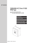
1
YASKAWA AC Drive-J1000
Compact V/f Control Drive
Technical Manual
Type: CIMR-JU
Models: 200 V Class, Three-Phase Input: 0.1 to 5.5 kW
200 V Class, Single-Phase Input: 0.1 to 2.2 kW
400 V Class, Three-Phase Input: 0.2 to 5.5 kW
To properly use the product, read this manual thoroughly
and retain for easy reference, inspection, and maintenance.
Ensure the end user receives this manual.
MANUAL NO. SIEP C710606 31A
Receiving
1
Mechanical Installation
2
Electrical Installation
3
Start-Up Programming &
Operation
4
Parameter Details
5
Troubleshooting
6
Periodic Inspection &
Maintenance
7
Peripheral Devices &
Options
8
Specifications
A
Parameter List
B
MEMOBUS/Modbus
Communications
C
Standards Compliance
D
This Page Intentionally Blank
Copyright © 2008 YASKAWA ELECTRIC CORPORATION. All rights reserved.
All rights reserved. No part of this publication may be reproduced, stored in a retrieval system, or transmitted, in
any form or by any means, mechanical, electronic, photocopying, recording, or otherwise, without the prior written
permission of Yaskawa. No patent liability is assumed with respect to the use of the information contained herein.
Moreover, because Yaskawa is constantly striving to improve its high-quality products, the information contained
in this manual is subject to change without notice. Every precaution has been taken in the preparation of this
manual. Yaskawa assumes no responsibility for errors or omissions. Neither is any liability assumed for damages
resulting from the use of the information contained in this publication.
2
YASKAWA ELECTRIC SIEP C710606 31A YASKAWA AC Drive – J1000 Technical Manual
Table of Contents
i. PREFACE & GENERAL SAFETY.................................................................... 9
i.1
Preface ....................................................................................................................... 10
Applicable Documentation....................................................................................................... 10
Symbols................................................................................................................................... 10
Terms and Abbreviations ........................................................................................................ 10
i.2
General Safety ........................................................................................................... 11
Supplemental Safety Information ............................................................................................ 11
Safety Messages..................................................................................................................... 11
Drive Label Warnings .............................................................................................................. 13
Warranty Information............................................................................................................... 14
Quick Reference...................................................................................................................... 14
1. RECEIVING .................................................................................................... 15
1.1 Section Safety............................................................................................................ 16
1.2 Model Number and Nameplate Check ..................................................................... 17
Nameplate ............................................................................................................................... 17
1.3 Component Names.................................................................................................... 19
IP20/Open-Chassis ................................................................................................................. 19
Front Views ............................................................................................................................. 21
2. MECHANICAL INSTALLATION..................................................................... 23
2.1 Section Safety............................................................................................................ 24
2.2 Mechanical Installation ............................................................................................. 26
Installation Environment .......................................................................................................... 26
Installation Orientation and Spacing........................................................................................ 27
Exterior and Mounting Dimensions ......................................................................................... 28
3. ELECTRICAL INSTALLATION ...................................................................... 31
3.1 Section Safety............................................................................................................ 32
3.2 Standard Connection Diagram................................................................................. 34
3.3 Main Circuit Connection Diagram............................................................................ 36
Single-Phase 200 V Class (CIMR-JoBA0001 ~ 0010) ........................................................... 36
Three-Phase 200 V Class (CIMR-Jo2A0001 ~
0020);
Three-Phase 400 V Class (CIMR-Jo4A0001 ~ 0011)........................................................... 36
3.4 Terminal Block Configuration .................................................................................. 37
3.5 Protective Covers ...................................................................................................... 38
YASKAWA ELECTRIC SIEP C710606 31A YASKAWA AC Drive – J1000 Technical Manual
3
Table of Contents
IP20/Open-Chassis Cover Removal and Installation ........................................................................ 38
3.6 Main Circuit Wiring..............................................................................................................39
Main Circuit Terminal Functions........................................................................................................ 39
Wire Gauges and Tightening Torque ................................................................................................ 39
Main Circuit Terminal Power Supply and Motor Wiring..................................................................... 40
3.7 Control Circuit Wiring .........................................................................................................42
Control Circuit Terminal Block Functions .......................................................................................... 42
Terminal Configuration ...................................................................................................................... 43
Wiring Procedure............................................................................................................................... 44
3.8 I/O Connections ...................................................................................................................46
Sinking/Sourcing Mode Switch.......................................................................................................... 46
3.9 Main Frequency Reference.................................................................................................48
DIP Switch S1 Analog Input Signal Selection ................................................................................... 48
3.10 Braking Resistor..................................................................................................................49
Installation ......................................................................................................................................... 49
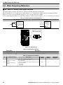
3.11 Interlocking with Connected Machinery ...........................................................................51
Drive Ready Signal............................................................................................................................ 51
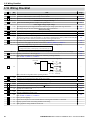
3.12 Wiring Checklist ..................................................................................................................52
4. START-UP PROGRAMMING & OPERATION ...................................................... 53
4.1 Section Safety......................................................................................................................54
4.2 Using the Digital LED Operator..........................................................................................56
Keys, Displays, and LEDs ................................................................................................................. 56
Digital Text Display............................................................................................................................ 57
LED Screen Displays ........................................................................................................................ 57
LO/RE LED and RUN LED Indications.............................................................................................. 57
Menu Structure for Digital LED Operator .......................................................................................... 58
4.3 The Drive and Programming Modes ..................................................................................59
Navigating the Drive and Programming Modes................................................................................. 59
Changing Parameter Settings or Values ........................................................................................... 61
Verifying Parameter Changes: Verify Menu ...................................................................................... 62
Switching Between LOCAL and REMOTE........................................................................................ 62
Parameters Available in the Setup Group ......................................................................................... 63
4.4 Start-up Flowchart...............................................................................................................64
Flowchart: Basic Start-up .................................................................................................................. 64
4.5 Powering Up the Drive ........................................................................................................65
Powering Up the Drive and Operation Status Display....................................................................... 65
V/f Pattern Setting ............................................................................................................................. 65
4.6 No-Load Operation Test Run..............................................................................................66
No-Load Operation Test Run ............................................................................................................ 66
4.7 Test Run with Load Connected..........................................................................................67
Test Run with the Load Connected ................................................................................................... 67
4.8 Verifying and Backing Up Parameter Settings .................................................................68
Parameter Access Level: A1-01........................................................................................................ 68
Password Settings: A1-04, A1-05 ..................................................................................................... 68
Copy Function (Optional) .................................................................................................................. 68
4.9 Test Run Checklist ..............................................................................................................69
4
YASKAWA ELECTRIC SIEP C710606 31A YASKAWA AC Drive – J1000 Technical Manual
Table of Contents
5. PARAMETER DETAILS ......................................................................................... 71
5.1 A: Initialization .....................................................................................................................72
A1: Initialization ................................................................................................................................. 72
5.2 b: Application.......................................................................................................................75
b1: Mode of Operation....................................................................................................................... 75
b2: DC Injection Braking.................................................................................................................... 79
5.3 C: Tuning..............................................................................................................................81
C1: Acceleration and Deceleration Times ......................................................................................... 81
C2: S-Curve Characteristics.............................................................................................................. 82
C3: Slip Compensation...................................................................................................................... 82
C4: Torque Compensation ................................................................................................................ 83
C6: Carrier Frequency....................................................................................................................... 83
5.4 d: Reference Settings .........................................................................................................86
d1: Frequency Reference.................................................................................................................. 86
d2: Frequency Upper/Lower Limits ................................................................................................... 87
d3: Jump Frequency.......................................................................................................................... 88
d4: Frequency Hold Function ............................................................................................................ 88
5.5 E: Motor Parameters ...........................................................................................................90
E1: V/f Characteristics....................................................................................................................... 90
E2: Motor 1 Parameters .................................................................................................................... 92
5.6 H: Terminal Functions.........................................................................................................94
H1: Multi-Function Digital Inputs ....................................................................................................... 94
H2: Multi-Function Output ................................................................................................................. 99
H3: Analog Input Terminal A1 Settings ........................................................................................... 103
H4: Multi-Function Analog Output Terminal AM.............................................................................. 106
H5: MEMOBUS/Modbus Serial Communication ............................................................................. 106
5.7 L: Protection Functions ....................................................................................................107
L1: Motor Protection Functions ....................................................................................................... 107
L2: Momentary Power Loss Ride-Thru............................................................................................ 108
L3: Stall Prevention ......................................................................................................................... 109
L4: Speed Agree ............................................................................................................................. 111
L5: Fault Restart.............................................................................................................................. 112
L6: Torque Detection....................................................................................................................... 112
L8: Hardware Protection.................................................................................................................. 113
5.8 n: Special Adjustments.....................................................................................................116
n1: Hunting Prevention.................................................................................................................... 116
n3: Overexcitation Deceleration ...................................................................................................... 116
5.9 o: Operator Related Settings............................................................................................117
o1: Display Settings and Selections ................................................................................................ 117
o2: Operator Key Selections ........................................................................................................... 117
o3: Copy Function ........................................................................................................................... 118
o4: Maintenance Monitor Settings................................................................................................... 119
5.10 U: Monitor Parameters ......................................................................................................121
U1: Operation Status Monitors ........................................................................................................ 121
U2: Fault History.............................................................................................................................. 121
U4: Maintenance Monitors .............................................................................................................. 121
6. TROUBLESHOOTING.......................................................................................... 123
6.1 Section Safety....................................................................................................................124
YASKAWA ELECTRIC SIEP C710606 31A YASKAWA AC Drive – J1000 Technical Manual
5
Table of Contents
6.2 Motor Performance Fine Tuning ......................................................................................126
Parameters for Tuning the Drive ..................................................................................................... 126
Motor Hunting and Oscillation Control Parameters ......................................................................... 126
6.3 Drive Alarms, Faults, and Errors .....................................................................................127
Types of Alarms, Faults, and Errors................................................................................................ 127
Alarm and Error Displays ................................................................................................................ 127
6.4 Fault Detection ..................................................................................................................129
Fault Displays, Causes and Possible Solutions .............................................................................. 129
6.5 Alarm Detection .................................................................................................................135
Alarm Codes, Causes, and Possible Solutions ............................................................................... 135
6.6 Operator Programming Errors .........................................................................................138
oPE Codes, Causes, and Possible Solutions.................................................................................. 138
6.7 Diagnosing and Resetting Faults.....................................................................................139
Fault Occurs Simultaneously with Power Loss ............................................................................... 139
If the Drive Still has Power After a Fault Occurs ............................................................................. 139
Viewing Fault History Data After Fault ............................................................................................ 139
Fault Reset Methods ....................................................................................................................... 139
6.8 Troubleshooting without Fault Display ...........................................................................140
Cannot Change Parameter Settings ............................................................................................... 140
Motor Does Not Rotate Properly after Pressing RUN Button or after Entering External Run
Command ...................................................................................................................................... 140
7. PERIODIC INSPECTION & MAINTENANCE ...................................................... 145
7.1 Section Safety....................................................................................................................146
7.2 Inspection ..........................................................................................................................148
Recommended Daily Inspection...................................................................................................... 148
Recommended Periodic Inspection................................................................................................. 148
7.3 Periodic Maintenance .......................................................................................................150
Replacement Parts.......................................................................................................................... 150
7.4 Drive Cooling Fans............................................................................................................151
Cooling Fan Replacement............................................................................................................... 151
8. PERIPHERAL DEVICES & OPTIONS ................................................................ 153
8.1
8.2
8.3
8.4
Section Safety....................................................................................................................154
Drive Options and Peripheral Devices ............................................................................156
Connecting Peripheral Devices .......................................................................................157
Installing Peripheral Devices ...........................................................................................158
Installing a Molded Case Circuit Breaker (MCCB) .......................................................................... 158
Installing a Leakage Breaker........................................................................................................... 158
Installing a Magnetic Contactor ....................................................................................................... 158
Connecting an AC or DC Reactor ................................................................................................... 159
Connecting a Surge Suppressor ..................................................................................................... 159
Connecting a Noise Filter ................................................................................................................ 160
Zero-Phase Reactor ........................................................................................................................ 161
Installing Fuses on the Input Side ................................................................................................... 162
Installing a Motor Thermal Overload (oL) Relay on the Drive Output ............................................. 162
NEMA Type 1 Kit............................................................................................................................. 163
8.5 Communication Options...................................................................................................167
6
YASKAWA ELECTRIC SIEP C710606 31A YASKAWA AC Drive – J1000 Technical Manual
Table of Contents
A. SPECIFICATIONS ................................................................................................ 169
A.1
A.2
A.3
A.4
A.5
A.6
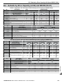
Heavy Duty and Normal Duty Ratings .............................................................................170
Single/Three-Phase 200 V Class Drive ............................................................................171
Three-Phase 400 V Class Drives ......................................................................................172
Drive Specifications ..........................................................................................................173
Drive Watt Loss Data ........................................................................................................175
Drive Derating Data ...........................................................................................................176
Temperature Derating ..................................................................................................................... 176
B. PARAMETER LIST............................................................................................... 177
B.1 Parameter Groups .............................................................................................................178
B.2 Parameter Table ................................................................................................................179
A: Initialization Parameters.............................................................................................................. 179
b: Application................................................................................................................................... 179
C: Tuning......................................................................................................................................... 180
d: References .................................................................................................................................. 181
E: Motor Parameters ....................................................................................................................... 182
H Parameters: Multi-Function Terminals......................................................................................... 184
L: Protection Function ..................................................................................................................... 186
n: Advanced Performance Set-Up................................................................................................... 190
o: Operator Related Parameters ..................................................................................................... 190
U: Monitors ...................................................................................................................................... 191
B.3 Defaults by Drive Capacity (o2-04) and ND/HD (C6-01) .................................................193
C. MEMOBUS/MODBUS COMMUNICATIONS........................................................ 195
C.1
C.2
C.3
C.4
Section Safety....................................................................................................................196
MEMOBUS/Modbus Configuration ..................................................................................197
Communication Specifications ........................................................................................198
Connecting to a Network ..................................................................................................199
Network Cable Connection.............................................................................................................. 199
Wiring Diagram for Multiple Connection.......................................................................................... 199
Network Termination ....................................................................................................................... 201
C.5 MEMOBUS/Modbus Setup Parameters ...........................................................................202
MEMOBUS/Modbus Serial Communication.................................................................................... 202
C.6 Drive Operations by MEMOBUS/Modbus........................................................................205
Observing the Drive Operation........................................................................................................ 205
Controlling the Drive........................................................................................................................ 205
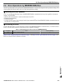
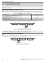
C.7 Communications Timing...................................................................................................206
Command Messages from Master to Drive..................................................................................... 206
Response Messages from Drive to Master ..................................................................................... 206
C.8 Message Format ................................................................................................................207
Message Content ............................................................................................................................ 207
Slave Address ................................................................................................................................. 207
Function Code ................................................................................................................................. 207
Data................................................................................................................................................. 207
Error Check ..................................................................................................................................... 207
C.9 Message Examples ...........................................................................................................210
Reading Drive MEMOBUS/Modbus Register Contents .................................................................. 210
YASKAWA ELECTRIC SIEP C710606 31A YASKAWA AC Drive – J1000 Technical Manual
7
Table of Contents
Loopback Test................................................................................................................................. 210
Writing to Multiple Registers............................................................................................................ 211
C.10 MEMOBUS/Modbus Data Table........................................................................................212
Command Data ............................................................................................................................... 212
Monitor Data.................................................................................................................................... 213
Broadcast Messages....................................................................................................................... 216
Fault History Contents..................................................................................................................... 217
Alarm Register Contents ................................................................................................................. 217
C.11 Changing Drive Parameters .............................................................................................218
Drive Operations on Parameter Change ......................................................................................... 218
Issuing an Enter Command............................................................................................................. 218
C.12 Communication Errors .....................................................................................................219
MEMOBUS/Modbus Error Codes.................................................................................................... 219
Slave Not Responding..................................................................................................................... 219
C.13 Self-Diagnostics ................................................................................................................220
D. STANDARDS COMPLIANCE .............................................................................. 221
D.1 Section Safety....................................................................................................................222
D.2 European Standards .........................................................................................................224
CE Low Voltage Directive Compliance............................................................................................ 224
EMC Guidelines Compliance .......................................................................................................... 225
D.3 UL Standards .....................................................................................................................229
UL Standards Compliance .............................................................................................................. 229
Drive Motor Overload Protection ..................................................................................................... 230
D.4 User Setting Table .............................................................................................................232
INDEX ................................................................................................................... 235
8
YASKAWA ELECTRIC SIEP C710606 31A YASKAWA AC Drive – J1000 Technical Manual
i
Preface & General Safety
This section provides safety messages pertinent to this product that, if not heeded, may result in fatality,
personal injury, or equipment damage. Yaskawa is not responsible for the consequences of ignoring
these instructions.
I.1
I.2
PREFACE...............................................................................................................10
GENERAL SAFETY...............................................................................................11
YASKAWA ELECTRIC SIEP C710606 31A YASKAWA AC Drive – J1000 Technical Manual
9
i.1 Preface
i.1
Preface
Yaskawa manufactures products used as components in a wide variety of industrial systems and equipment. The selection and
application of Yaskawa products remain the responsibility of the equipment manufacturer or end user. Yaskawa accepts no
responsibility for the way its products are incorporated into the final system design. Under no circumstances should any
Yaskawa product be incorporated into any product or design as the exclusive or sole safety control. Without exception, all
controls should be designed to detect faults dynamically and fail safely under all circumstances. All systems or equipment
designed to incorporate a product manufactured by Yaskawa must be supplied to the end user with appropriate warnings and
instructions as to the safe use and operation of that part. Any warnings provided by Yaskawa must be promptly provided to
the end user. Yaskawa offers an express warranty only as to the quality of its products in conforming to standards and
specifications published in the Yaskawa manual. NO OTHER WARRANTY, EXPRESSED OR IMPLIED, IS OFFERED.
Yaskawa assumes no liability for any personal injury, property damage, losses, or claims arising from misapplication of its
products.
u Applicable Documentation
The following manuals are available for J1000 series drives:
J1000 Series Compact V/f Control Drive Quick Start Guide
Read this manual first. This guide is packaged together with the product. It contains basic information
required to install and wire the drive. This guide provides basic programming and simple setup and
adjustment.
J1000 Series Compact V/f Control Drive Technical Manual
This manual describes installation, wiring, operation procedures, functions, troubleshooting,
maintenance, and inspections to perform before operation.
u Symbols
Note: Indicates a supplement or precaution that does not cause drive damage.
TERMS
Indicates a term or definition used in this manual.
u Terms and Abbreviations
• Drive: Yaskawa J1000 Series Drive
10
YASKAWA ELECTRIC SIEP C710606 31A YASKAWA AC Drive – J1000 Technical Manual
i.2 General Safety
i.2
General Safety
u Supplemental Safety Information
General Precautions
• The diagrams in this manual may be indicated without covers or safety shields to show details. Restore covers or shields before operating
the drive and run the drive according to the instructions described in this manual.
• Any illustrations, photographs, or examples used in this manual are provided as examples only and may not apply to all products to
which this manual is applicable.
• The products and specifications described in this manual or the content and presentation of the manual may be changed without notice
to improve the product and/or the manual.
• When ordering a new copy of the manual due to damage or loss, contact your Yaskawa representative or the nearest Yaskawa sales
office and provide the manual number shown on the front cover.
• If nameplate becomes worn or damaged, order a replacement from your Yaskawa representative or the nearest Yaskawa sales office.
WARNING
Read and understand this manual before installing, operating or servicing this drive. The drive must be installed according
to this manual and local codes.
The following conventions are used to indicate safety messages in this manual. Failure to heed these messages could result
in serious or possibly even fatal injury or damage to the products or to related equipment and systems.
DANGER
Indicates a hazardous situation, which, if not avoided, will result in death or serious injury.
WARNING
Indicates a hazardous situation, which, if not avoided, could result in death or serious injury.
WARNING! will also be indicated by a bold key word embedded in the text followed by an italicized safety message.
CAUTION
Indicates a hazardous situation, which, if not avoided, could result in minor or moderate injury.
CAUTION! will also be indicated by a bold key word embedded in the text followed by an italicized safety message.
NOTICE
Indicates a property damage message.
NOTICE: will also be indicated by a bold key word embedded in the text followed by an italicized safety message.
u Safety Messages
DANGER
Heed the safety messages in this manual.
Failure to comply will result in death or serious injury.
The operating company is responsible for any injuries or equipment damage resulting from failure to heed the warnings in
this manual.
Electrical Shock Hazard
Do not connect or disconnect wiring while the power is on.
Failure to comply will result in death or serious injury.
YASKAWA ELECTRIC SIEP C710606 31A YASKAWA AC Drive – J1000 Technical Manual
11
i.2 General Safety
DANGER
Before servicing, disconnect all power to the equipment. The internal capacitor remains charged even after the power supply
is turned off. The charge indicator LED will extinguish when the DC bus voltage is below 50 Vdc. To prevent electric shock,
wait at least one minute after all indicators are OFF and measure the DC bus voltage level to confirm safe level.
WARNING
Sudden Movement Hazard
System may start unexpectedly upon application of power, resulting in death or serious injury.
Clear all personnel from the drive, motor and machine area before applying power. Secure covers, couplings, shaft keys and
machine loads before applying power to the drive.
Electrical Shock Hazard
Do not attempt to modify or alter the drive in any way not explained in this manual.
Failure to comply could result in death or serious injury.
Yaskawa is not responsible for any modification of the product made by the user. This product must not be modified.
Do not allow unqualified personnel to use equipment.
Failure to comply could result in death or serious injury.
Maintenance, inspection, and replacement of parts must be performed only by authorized personnel familiar with installation,
adjustment and maintenance of AC drives.
Do not remove covers or touch circuit boards while the power is on.
Failure to comply could result in death or serious injury.
Fire Hazard
Do not use an improper voltage source.
Failure to comply could result in death or serious injury by fire.
Verify that the rated voltage of the drive matches the voltage of the incoming power supply before applying power.
Crush Hazard
Do not use this drive in lifting applications without installing external safety circuitry to prevent accidental dropping
of the load.
The drive does not possess built-in load drop protection for lifting applications.
Failure to comply could result in death or serious injury from falling loads.
Install electrical and/or mechanical safety circuit mechanisms independent of drive circuitry.
CAUTION
Crush Hazard
Do not carry the drive by the front cover.
Failure to comply may result in minor or moderate injury from the main body of the drive falling.
12
YASKAWA ELECTRIC SIEP C710606 31A YASKAWA AC Drive – J1000 Technical Manual
i.2 General Safety
NOTICE
Observe proper electrostatic discharge procedures (ESD) when handling the drive and circuit boards.
Failure to comply may result in ESD damage to the drive circuitry.
Never connect or disconnect the motor from the drive while the drive is outputting voltage.
Improper equipment sequencing could result in damage to the drive.
Do not perform a withstand voltage test on any part of the drive.
Failure to comply could result in damage to the sensitive devices within the drive.
Do not operate damaged equipment.
Failure to comply could result in further damage to the equipment.
Do not connect or operate any equipment with visible damage or missing parts.
Install adequate branch circuit short circuit protection per applicable codes.
Failure to comply could result in damage to the drive.
The drive is suitable for circuits capable of delivering not more than 30,000 RMS symmetrical Amperes, 240 Vac maximum
(200 V Class) and 480 Vac maximum (400 V Class).
Do not expose the drive to halogen group disinfectants.
Failure to comply may cause damage to the electrical components in the drive.
Do not pack the drive in wooden materials that have been fumigated or sterilized.
Do not sterilize the entire package after the product is packed.
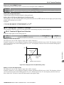
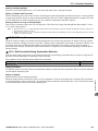
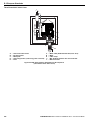
u Drive Label Warnings
Always heed the warning information listed in Figure i.1 in the position shown in Figure i.2.
WARNING Risk of electric shock.
Read manual before installing.
Wait 1 minute for capacitor discharge after
disconnecting power supply.
To conform to
requirements, make sure
to ground the supply neutral for 400V class.
Figure i.1 Warning Information
Warning
Label
Figure i.2 Warning Information Position
YASKAWA ELECTRIC SIEP C710606 31A YASKAWA AC Drive – J1000 Technical Manual
13
i.2 General Safety
u Warranty Information
n Restrictions
The J1000 was not designed or manufactured for use in devices or systems that may directly affect or threaten human lives or
health.
Customers who intend to use the product described in this manual for devices or systems relating to transportation, health
care, space aviation, atomic power, electric power, or in underwater applications must first contact their Yaskawa
representatives or the nearest Yaskawa sales office.
This product has been manufactured under strict quality-control guidelines. However, if this product is to be installed in any
location where failure of this product could involve or result in a life-and-death situation or loss of human life or in a facility
where failure may cause a serious accident or physical injury, safety devices must be installed to minimize the likelihood of
any accident.
u Quick Reference
Run a Motor of One-Frame Larger Capacity
When using this drive for variable torque loads such as fans and pumps, a motor one frame size larger can be used.
Know the Details of Safety Measures
The functions listed below affect the safe operation of the drive. Ensure that the settings fit the application requirements prior to operation.
Safe operations. Run by power on. Parameter setting b1-17.
LED operator stop key priority selection. Parameter o2-02.
Enter press required after changing the keypad frequency reference. Parameter o2-05.
Operation interlock when program mode is selected. Parameter b1-08.
Standards Compliance
Refer to European Standards on page 224 and Refer to UL Standards on page 229.
C
UL
R
US
LISTED
14
YASKAWA ELECTRIC SIEP C710606 31A YASKAWA AC Drive – J1000 Technical Manual
1
Receiving
This chapter describes the proper inspections to perform after receiving the drive and illustrates the
different enclosure types and components.
1.1
1.2
1.3
SECTION SAFETY.................................................................................................16
MODEL NUMBER AND NAMEPLATE CHECK....................................................17
COMPONENT NAMES...........................................................................................19
YASKAWA ELECTRIC SIEP C710606 31A YASKAWA AC Drive – J1000 Technical Manual
15
1.1 Section Safety
1.1
Section Safety
CAUTION
Do not carry the drive by the front cover.
Failure to comply may cause the main body of the drive to fall, resulting in minor or moderate injury.
NOTICE
Observe proper electrostatic discharge procedures (ESD) when handling the drive and circuit boards.
Failure to comply may result in ESD damage to the drive circuitry.
A motor connected to a PWM drive may operate at a higher temperature than a utility-fed motor and the operating
speed range may reduce motor cooling capacity.
Ensure that the motor is suitable for drive duty and/or the motor service factor is adequate to accommodate the additional
heating with the intended operating conditions.
16
YASKAWA ELECTRIC SIEP C710606 31A YASKAWA AC Drive – J1000 Technical Manual
1.2 Model Number and Nameplate Check
1.2
Model Number and Nameplate Check
Please perform the following tasks after receiving the drive:
• Inspect the drive for damage.
If the drive appears damaged upon receipt, contact the shipper immediately.
• Verify receipt of the correct model by checking the information on the nameplate.
• If you have received the wrong model or the drive does not function properly, contact your supplier.
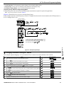
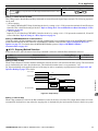
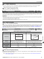
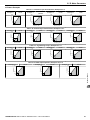
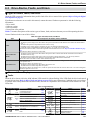
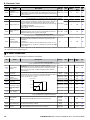
u Nameplate
Drive model
Input
specifications
Output
specifications
Lot number
Serial number
CIMR-JU2A0004BAA
MODEL :
C U L US
MAX APPLI. MOTOR : 3.5A/3.0A
REV : A
LISTED
INPUT : AC3PH 200-240V 50 / 60Hz 2.7A / 1.4A
IND.CONT.EQ.
OUTPUT : AC3PH 0-240V 0-400Hz 1.2A / 0.8A
7J48 B
MASS : 0.9 kg
PRG : 1010
O/N
:
S/N
:
FILE NO : E131457
IP20
YASKAWA ELECTRIC CORPORATION
Software version
PASS
MADE IN JAPAN
CIMR - J U 2
Drive
J1000
Series
No.
U
Region
Code
A
0001
B
No.
Customized
Specifications
No.
A
Standard model
B
Receiving
Figure 1.1 Nameplate Information
A
A
Enclosure
Type
Design
Revision
Order
IP20
1
USA
A
Japan
C
Europe
No.
No.
B
Voltage Class
1-phase, 200-240 Vac
2
3-phase, 200-240 Vac
4
3-phase, 380-480 Vac
A
M
N
S
Environmental
Specification <1>
Standard
Humidity- and
dust-resistant
Oil-resistant
Vibration-resistant
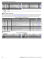
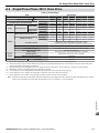
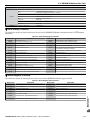
n Single-Phase 200 V
No.
0001
0002
0003
0006
0010
Normal Duty
Max. Motor Capacity
kW
0.2
0.4
0.75
1.1
2.2
Rated Output
Current A
1.2
1.9
3.3
6.0
9.6
YASKAWA ELECTRIC SIEP C710606 31A YASKAWA AC Drive – J1000 Technical Manual
No.
0001
0002
0003
0006
0010
Heavy Duty
Max. Motor Capacity
kW
0.1
0.2
0.4
0.75
1.5
Rated Output
Current A
0.8
1.6
3.0
5.0
8.0
17
1.2 Model Number and Nameplate Check
n Three-Phase 200 V
No.
0001
0002
0004
0006
0010
0012
0020
Normal Duty
Max Motor Capacity
kW
0.2
0.4
0.75
1.1
2.2
3.0
5.5
Rated Output
Current A
1.2
1.9
3.5
6.0
9.6
12.0
19.6
No.
0001
0002
0004
0006
0010
0012
0020
Heavy Duty
Max Motor Capacity
kW
0.1
0.2
0.4
1.1
1.5
2.2
3.7
Rated Output
Current A
0.8
1.6
3.5
6.0
9.6
12.0
17.5
Heavy Duty
Max. Motor Capacity
kW
0.2
0.4
0.75
1.5
2.2
3.0
3.7
Rated Output
Current A
1.2
1.8
3.4
4.8
5.5
7.2
9.2
n Three-Phase 400 V
No.
0001
0002
0004
0005
0007
0009
0011
Normal Duty
Max. Motor Capacity
kW
0.4
0.75
1.5
2.2
3.0
3.7
5.5
Rated Output
Current A
1.2
2.1
4.1
5.4
6.9
8.8
11.1
No.
0001
0002
0004
0005
0007
0009
0011
<1> Drives with these specifications do not guarantee complete protection for the specified environmental condition.
18
YASKAWA ELECTRIC SIEP C710606 31A YASKAWA AC Drive – J1000 Technical Manual
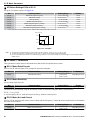
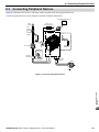
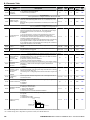
1.3 Component Names
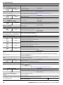
1.3
Component Names
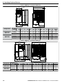
This section illustrates the drive components as they are mentioned in this manual.
u IP20/Open-Chassis
n Single-Phase AC200 V CIMR-JoBA0001B ~ 0003B
Three-Phase AC200 V CIMR-Jo2A0001B ~ 0006B
K
J
A
I
H
B
F
G
C
D
E
–
–
–
–
–
–
Mounting hole
Heatsink
Cable cover
Terminal cover
Front cover screw
Option connector cover
G – Front cover
H – LED operator Refer to Using the Digital LED
Operator on page 56
I – Case
J – Cooling fan <1>
K – Fan cover <1>
Receiving
A
B
C
D
E
F
Figure 1.2 Exploded View of IP20/Open-Chassis Type Components
Three-Phase AC200 V CIMR-Jo2A0006B
1
<1> The drives CIMR-JoBA0001B ~ 0003B and CIMR-Jo2A0001B ~ 0004B do not have a cooling fan or a cooling fan cover.
YASKAWA ELECTRIC SIEP C710606 31A YASKAWA AC Drive – J1000 Technical Manual
19
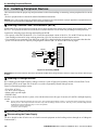
1.3 Component Names
n Single-Phase AC200 V CIMR-JoBA0006B ~ 0010B
Three-Phase AC200 V CIMR-Jo2A0010B ~ 0020B
Three-Phase AC400 V CIMR-Jo4A0001B ~ 0011B
L
K
J
A
I
B
G
H
C
D
F
A
B
C
D
E
F
–
–
–
–
–
–
Mounting hole
Heatsink
Cable cover
Terminal cover
Bottom cover
Front cover screw
E
G – Option connector cover
H – Front cover
I – LED operator Refer to Using the Digital LED
Operator on page 56
J – Case
K – Cooling fan <1>
L – Fan cover <1>
Figure 1.3 Exploded view of IP20/Open-Chassis Type Components
Three-Phase AC200 V CIMR-Jo2A0012B
<1> The drives CIMR-JoBA0006B and CIMR-Jo4A0001B ~ 0004B do not have a cooling fan or a cooling fan cover.
20
YASKAWA ELECTRIC SIEP C710606 31A YASKAWA AC Drive – J1000 Technical Manual
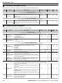
1.3 Component Names
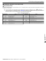
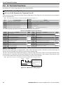
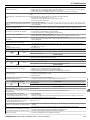
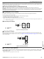
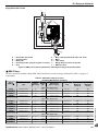
u Front Views
CIMR-J 2A0006B
CIMR-J 2A0012B
A
G
B
C
F
D
A
G
B
C
F
D
E
A – DIP switch S1 Refer to DIP Switch S1 Analog Input
Signal Selection on page 48
B – DIP switch S3 Refer to Sinking/Sourcing Mode
Switch on page 46
C – Control circuit terminal Refer to Control Circuit
Wiring on page 42
D – Main circuit terminal Refer to Wiring the Main
Circuit Terminal on page 41
E
E – Ground terminal
F – Terminal cover
G – Option unit connector Refer to Communication
Options on page 167
Receiving
Figure 1.4 Front Views of Drives
1
YASKAWA ELECTRIC SIEP C710606 31A YASKAWA AC Drive – J1000 Technical Manual
21
1.3 Component Names
This Page Intentionally Blank
22
YASKAWA ELECTRIC SIEP C710606 31A YASKAWA AC Drive – J1000 Technical Manual
2
Mechanical Installation
This chapter explains how to properly mount and install the drive.
2.1
2.2
SECTION SAFETY.................................................................................................24
MECHANICAL INSTALLATION.............................................................................26
YASKAWA ELECTRIC SIEP C710606 31A YASKAWA AC Drive – J1000 Technical Manual
23
2.1 Section Safety
2.1
Section Safety
WARNING
Fire Hazard
Provide sufficient cooling when installing the drive inside an enclosed panel or cabinet.
Failure to comply could result in overheating and fire.
When multiple drives are placed inside the same enclosure panel, install proper cooling to ensure air entering the enclosure
does not exceed 40 °C.
CAUTION
Crush Hazard
Do not carry the drive by the front cover.
Failure to comply may result in minor or moderate injury from the main body of the drive falling.
NOTICE
Observe proper electrostatic discharge (ESD) procedures when handling the drive.
Failure to comply could result in ESD damage to the drive circuitry.
It may be difficult to perform maintenance on the cooling fans of drives installed in a vertical row inside an enclosure.
Ensure adequate spacing at the top of the drive to perform cooling fan replacement when required.
Operating the motor in the low-speed range diminishes the cooling effects, increases motor temperature, and may
lead to motor damage by overheating.
Reduce the motor torque in the low-speed range whenever using a standard blower cooled motor. If 100% torque is required
continuously at low speed, consider using a special drive or vector motor. Select a motor that is compatible with the required
load torque and operating speed range.
Do not operate motors above the maximum rated RPM.
Failure to comply may lead to bearing or other mechanical motor failures.
The speed range for continuous operation differs according to the lubrication method and motor manufacturer.
If the motor is to be operated at a speed higher than the rated speed, consult with the manufacturer.
Continuously operating an oil-lubricated motor in the low-speed range may result in burning.
24
YASKAWA ELECTRIC SIEP C710606 31A YASKAWA AC Drive – J1000 Technical Manual
2.1 Section Safety
NOTICE
Mechanical Installation
When the input voltage is 440 V or higher or the wiring distance is greater than 100 meters, pay special attention to
the motor insulation voltage or use a drive-rated motor.
Failure to comply could lead to motor winding failure.
Motor vibration may increase when operating a machine in variable-speed mode, if that machine previously operated
at a constant speed.
Install vibration-proof rubber on the motor base or use the frequency jump function to skip a frequency resonating the
machine.
The motor may require more acceleration torque with drive operation than with a commercial power supply.
Set a proper V/f pattern by checking the load torque characteristics of the machine to be used with the motor.
The rated input current of submersible motors is higher than the rated input current of standard motors.
Select an appropriate drive according to its rated output current. When the distance between the motor and drive is long, use
a cable thick enough to connect the motor to the drive to prevent motor torque reduction.
When using an explosion-proof motor, it must be subject to an explosion-proof test in conjunction with the drive.
This is also applicable when an existing explosion-proof motor is to be operated with the drive. Since the drive itself is not
explosion-proof, always install it in a safe place.
Do not use a drive for a single-phase motor.
Replace the motor with a three-phase motor.
If an oil-lubricated gearbox or speed reducer is used in the power transmission mechanism, oil lubrication will be
affected when the motor operates only in the low speed range.
The power transmission mechanism will make noise and experience problems with service life and durability if the motor
is operated at a speed higher than the rated speed.
2
YASKAWA ELECTRIC SIEP C710606 31A YASKAWA AC Drive – J1000 Technical Manual
25
2.2 Mechanical Installation
2.2
Mechanical Installation
This section outlines specifications, procedures, and environment for proper mechanical installation of the drive.
u Installation Environment
To help prolong the optimum performance life of the drive, install the drive in the proper environment. The table below provides
a description of the appropriate environment for the drive.
Environment
Installation Area
Ambient Temperature
Humidity
Storage Temperature
Surrounding Area
Altitude
Vibration
Orientation
Table 2.1 Installation Environment
Conditions
Indoors
-10 °C to +50 °C (IP20/Open-Chassis)
Drive reliability improves in environments without wide temperature fluctuations.
When using an enclosure panel, install a cooling fan or air conditioner in the area to ensure that the air temperature inside
the enclosure does not exceed the specified levels.
Do not allow ice to develop on the drive.
95% RH or less and free of condensation
-20 °C to +60 °C
Install the drive in an area free from:
• oil mist and dust
• metal shavings, oil, water or other foreign materials
• radioactive materials
• combustible materials (e.g., wood)
• harmful gases and liquids
• excessive vibration
• chlorides
• direct sunlight
1000 m or lower
10 to 20 Hz at 9.8 m/s2
20 to 55 Hz at 5.9 m/s2
Install the drive vertically to maintain maximum cooling effects.
NOTICE: Prevent foreign matter such as metal shavings or wire clippings from falling into the drive during installation and project
construction. Failure to comply could result in damage to the drive. Place a temporary cover over the top of the drive during installation.
Remove the temporary cover before startup, as the cover will reduce ventilation and cause the drive to overheat.
26
YASKAWA ELECTRIC SIEP C710606 31A YASKAWA AC Drive – J1000 Technical Manual
2.2 Mechanical Installation
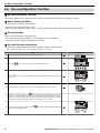
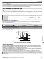
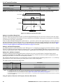
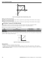
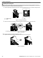
u Installation Orientation and Spacing
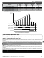
Install the drive upright as illustrated in Figure 2.1 to maintain proper cooling.
A
B
A – Correct
B
B – Incorrect
Figure 2.1 Correct Installation Orientation
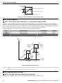
n Single Drive Installation
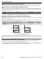
Figure 2.2 explains the required installation spacing to maintain sufficient space for airflow and wiring. Install the heatsink
against a closed surface to avoid diverting cooling air around the heatsink.
Side Clearance
A
A
Top/Bottom Clearance
C
B
A – 30 mm minimum
B – Airflow direction
Mechanical Installation
C
C – 100 mm minimum
Figure 2.2 Correct Installation Spacing
n Multiple Drive Installation
When installing multiple drives into the same enclosure panel, mount the drives according to Figure 2.2. When mounting
drives with a minimum side-by-side clearance of 2 mm according to Figure 2.3, derating must be considered and parameter
L8-35 must be set. Refer to Parameter List on page 177.
YASKAWA ELECTRIC SIEP C710606 31A YASKAWA AC Drive – J1000 Technical Manual
27
2
2.2 Mechanical Installation
A
B
2 mm
B
C
D
C
A – Line up the tops of the drives.
B – 30 mm minimum
C – 100 mm minimum
D – Airflow direction
Figure 2.3 Space Between Drives (Side-by-Side Mounting)
Note: When installing drives of different heights in the same enclosure panel, the tops of the drives should line up. Leave space between the top and
bottom of stacked drives for cooling fan replacement if required. Using this method, it is possible to replace the cooling fans later.
u Exterior and Mounting Dimensions
Refer to NEMA Type 1 Kit on page 163 for exterior and mounting dimensions for NEMA Type 1.
28
YASKAWA ELECTRIC SIEP C710606 31A YASKAWA AC Drive – J1000 Technical Manual
2.2 Mechanical Installation
n IP20/Open-Chassis Drives
Table 2.2 IP20/Open-Chassis (without an EMC filter)
D2
t1
2-M4
W
H2
H1
H
W1
D1
D
Voltage Class
Single-Phase
200 V Class
Three-Phase
200 V Class
Drive Model
CIMR-Jo
BA0001B
BA0002B
BA0003B
2A0001B
2A0002B
2A0004B
2A0006B
W
2.7
2.7
2.7
2.7
2.7
2.7
2.7
H
5.0
5.0
5.0
5.0
5.0
5.0
5.0
D
3.0
3.0
4.6
3.0
3.0
4.3
5.0
W1
2.2
2.2
2.2
2.2
2.2
2.2
2.2
Dimensions (in)
H1
H2
4.6
0.2
4.6
0.2
4.6
0.2
4.6
0.2
4.6
0.2
4.6
0.2
4.6
0.2
D1
0.3
0.3
1.5
0.3
0.3
1.5
2.3
D2
2.7
2.7
4.3
2.7
2.7
3.9
4.7
t1
0.1
0.1
0.2
0.1
0.1
0.2
0.2
Weight (lb.)
1.3
1.3
2.2
1.3
1.3
2.0
2.4
Table 2.3 IP20/Open-Chassis (without an EMC filter)
W1
D2
H1
H
Mechanical Installation
4-M4
2
t1
H2
W
D1
D
Voltage Class
Single-Phase
200 V Class
Three-Phase
200 V Class
Three-Phase
400 V Class
Drive Model
CIMR-Jo
BA0006B
BA0010B
2A0010B
2A0012B
2A0020B
4A0001B
4A0002B
4A0004B
4A0005B
4A0007B
4A0009B
4A0011B
W
4.3
4.3
4.3
4.3
5.5
4.3
4.3
4.3
4.3
4.3
4.3
5.5
H
5.0
5.0
5.0
5.0
5.0
5.0
5.0
5.0
5.0
5.0
5.0
5.0
D
5.4
6.1
5.1
5.4
5.6
3.2
3.9
5.4
6.1
6.1
6.1
5.6
W1
3.8
3.8
3.8
3.8
5.0
3.8
3.8
3.8
3.8
3.8
3.8
5.0
YASKAWA ELECTRIC SIEP C710606 31A YASKAWA AC Drive – J1000 Technical Manual
Dimensions (in)
H1
H2
D1
4.6
0.2
2.3
4.6
0.2
2.3
4.6
0.2
2.3
4.6
0.2
2.3
4.6
0.2
2.6
4.6
0.2
0.4
4.6
0.2
1.1
4.6
0.2
2.3
4.6
0.2
2.3
4.6
0.2
2.3
4.6
0.2
2.3
4.6
0.2
2.6
D2
5.1
5.7
4.7
5.1
5.3
2.9
3.6
5.1
5.7
5.7
5.7
5.3
t1
0.2
0.2
0.2
0.2
0.2
0.2
0.2
0.2
0.2
0.2
0.2
0.2
Weight (lb.)
3.8
4.0
3.8
3.8
5.3
2.2
2.7
3.8
3.8
3.8
3.8
5.3
29
2.2 Mechanical Installation
This Page Intentionally Blank
30
YASKAWA ELECTRIC SIEP C710606 31A YASKAWA AC Drive – J1000 Technical Manual
3
Electrical Installation
This chapter explains proper procedures for wiring the control circuit terminals, motor and power
supply.
3.1
3.2
3.3
3.4
3.5
3.6
3.7
3.8
3.9
3.10
3.11
3.12
SECTION SAFETY.................................................................................................32
STANDARD CONNECTION DIAGRAM.................................................................34
MAIN CIRCUIT CONNECTION DIAGRAM............................................................36
TERMINAL BLOCK CONFIGURATION................................................................37
PROTECTIVE COVERS.........................................................................................38
MAIN CIRCUIT WIRING.........................................................................................39
CONTROL CIRCUIT WIRING................................................................................42
I/O CONNECTIONS................................................................................................46
MAIN FREQUENCY REFERENCE........................................................................48
BRAKING RESISTOR............................................................................................49
INTERLOCKING WITH CONNECTED MACHINERY............................................51
WIRING CHECKLIST.............................................................................................52
YASKAWA ELECTRIC SIEP C710606 31A YASKAWA AC Drive – J1000 Technical Manual
31
3.1 Section Safety
3.1
Section Safety
DANGER
Electrical Shock Hazard
Do not connect or disconnect wiring while the power is on.
Failure to comply will result in death or serious injury.
WARNING
Electrical Shock Hazard
Do not operate equipment with covers removed.
Failure to comply could result in death or serious injury.
The diagrams in this section may show drives without covers or safety shields to show details. Be sure to reinstall covers or
shields before operating the drives and run the drives according to the instructions described in this manual.
Always ground the motor-side grounding terminal.
Improper equipment grounding could result in death or serious injury by contacting the motor case.
Do not perform work on the drive while wearing loose clothing, jewelry or without eye protection.
Failure to comply could result in death or serious injury.
Remove all metal objects such as watches and rings, secure loose clothing, and wear eye protection before beginning work
on the drive.
Do not remove covers or touch circuit boards while the power is on.
Failure to comply could result in death or serious injury.
Do not allow unqualified personnel to perform work on the drive.
Failure to comply could result in death or serious injury.
Installation, maintenance, inspection, and servicing must be performed only by authorized personnel familiar with
installation, adjustment, and maintenance of AC drives.
Do not touch any terminals before the capacitors have fully discharged.
Failure to comply could result in death or serious injury.
Before wiring terminals, disconnect all power to the equipment. The internal capacitor remains charged even after the power
supply is turned off. The charge indicator LED will extinguish when the DC bus voltage is below 50 Vdc. To prevent electric
shock, wait at least one minute after all indicators are off and measure the DC bus voltage level to confirm safe level.
Fire Hazard
Tighten all terminal screws to the specified tightening torque.
Loose electrical connections could result in death or serious injury by fire due to overheating of electrical connections.
Do not use improper combustible materials.
Failure to comply could result in death or serious injury by fire.
Attach the drive to metal or other noncombustible material.
Do not use an improper voltage source.
Failure to comply could result in death or serious injury by fire.
Verify that the rated voltage of the drive matches the voltage of the incoming power supply before applying power.
32
YASKAWA ELECTRIC SIEP C710606 31A YASKAWA AC Drive – J1000 Technical Manual
3.1 Section Safety
NOTICE
Electrical Installation
Observe proper electrostatic discharge procedures (ESD) when handling the drive and circuit boards.
Failure to comply may result in ESD damage to the drive circuitry.
Never connect or disconnect the motor from the drive while the drive is outputting voltage.
Improper equipment sequencing could result in damage to the drive.
Do not use unshielded cable for control wiring.
Failure to comply may cause electrical interference resulting in poor system performance. Use shielded, twisted-pair wires
and ground the shield to the ground terminal of the drive.
Check all the wiring to ensure that all connections are correct after installing the drive and connecting any other
devices.
Failure to comply could result in damage to the drive.
Do not modify the drive circuitry.
Failure to comply could result in damage to the drive and will void warranty.
Yaskawa is not responsible for any modification of the product made by the user. This product must not be modified.
3
YASKAWA ELECTRIC SIEP C710606 31A YASKAWA AC Drive – J1000 Technical Manual
33
3.2 Standard Connection Diagram
3.2
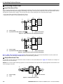
Standard Connection Diagram
Connect the drive and peripheral devices as shown in Figure 3.1. It is possible to run the drive via the digital operator without
connecting digital I/O wiring. This section does not discuss drive operation; Refer to Start-Up Programming & Operation
on page 53 for instructions on operating the drive.
NOTICE: Inadequate branch short circuit protection could result in damage to the drive. Install adequate branch circuit short circuit protection
per applicable codes. The drive is suitable for circuits capable of delivering not more than 30,000 RMS symmetrical amperes, 240 Vac
maximum (200 V Class) and 480 Vac maximum (400 V Class).
NOTICE: When the input voltage is 440 V or higher or the wiring distance is greater than 100 meters, pay special attention to the motor
insulation voltage or use a drive duty motor. Failure to comply could lead to motor insulation breakdown.
NOTICE: Do not connect AC control circuit ground to drive enclosure. Improper drive grounding can cause control circuit malfunction.
NOTICE: The minimum load for the multi-function relay output MA-MB-MC is 10 mA.
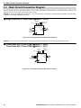
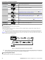
_
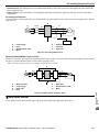
Terminals +1, +2, , B1, and B2
are for connecting options.
Never connect power supply
lines to these terminals.
2 MCCB
For single phase 200 V
r1
power supply, use
s1
R/L1 and S/L2.
t1
MC
1 MCCB
Three phase R/L1
power supply S/L2
200 to 240 V
T/L3
<1>
<3>
SA
MC
THRX
Thermal relay for
motor cooling fan
SA
TRX
MC
SA
TRX
MC MA
Thermal relay
Braking resistor
(option)
(option)
Jumper
+2
S/L2
-
+1
B1
B2
J1000
R/L1
T/L3
Motor
r1
FU
s1
FV
V
V/T2
S1
Reverse run/stop
S2
External fault
S3
Option unit
connector
Fault reset
Multi-step
speed 1
main/aux switch
S4
DIP switch S1
I
M
W
W/T3
Forward run/stop
M
U
U/T1
Control circuit
Cooling fan
FW
t1
Main circuit
<4>
2 MCCB THRX OFF ON MC
<2>
DC reactor
(option)
Ground
10 or less (400 V class)
100 or less (200 V class)
V
S5
Digital output
250 Vac, 10 mA to 1 A
30 Vdc, 10 mA to 1 A
(default setting)
<6>
+24 V 8 mA
MA Fault
Fault relay
MB
Digital inputs
(default setting)
<5>
SC
DIP
switch S3
24 V
Sink
MC
Source
Shield ground
terminal
2k
Main speed
frequency
reference.
Multi-function
programmable
Setting power supply
+10.5 max. 20 mA
AM
A1 0 to +10 V (20 k )
(0)4 to 20 mA (250 )
AC
+V
Analog monitor
+ output
AM
0 to +10 Vdc
- (2 mA)
AC
<7>
Monitor
output
shielded line
main circuit terminal
twisted-pair shielded line
control terminal
Figure 3.1 Drive Standard Connection Diagram (200 V Class Example)
<1>
<2>
<3>
<4>
34
Remove the jumper when installing an optional DC reactor.
The MC on the input side of the main circuit should open when the thermal relay is triggered.
Self-cooled motors do not require separate cooling fan motor wiring.
Connected using sequence input signal (S1 to S5) from NPN transistor; Default: sink mode (0 V com).
YASKAWA ELECTRIC SIEP C710606 31A YASKAWA AC Drive – J1000 Technical Manual
3.2 Standard Connection Diagram
<5> Use only a +24 V internal power supply in sinking mode; the source mode requires an external power supply Refer to
I/O Connections on page 46.
<6> Minimum load: 5 Vdc, 10 mA (reference value).
<7> Monitor outputs work with devices such as analog frequency meters, ammeters, voltmeters and wattmeters; they are
not intended for use as a feedback-type of signal.
WARNING! Sudden Movement Hazard. Do not close the wiring for the control circuit unless the multifunction input terminal parameter is
properly set (S5 for 3-Wire; H1-05 = “0”). Improper sequencing of run/stop circuitry could result in death or serious injury from moving
equipment.
WARNING! Sudden Movement Hazard. Ensure start/stop and safety circuits are wired properly and in the correct state before energizing
the drive. Failure to comply could result in death or serious injury from moving equipment. When programmed for 3-Wire control, a momentary
closure on terminal S1 may cause the drive to start.
WARNING! When 3-Wire sequence is used, set the drive to 3-Wire sequence before wiring the control terminals and ensure parameter
b1-17 is set to 0 (drive does not accept a run command at power up (default). If the drive is wired for 3-Wire sequence but set up for 2-Wire
sequence (default) and if parameter b1-17 is set to 1 (drive accepts a Run command at power up), the motor will rotate in reverse direction
at power up of the drive and may cause injury.
Figure 3.2 illustrates an example of a 3-Wire sequence.
Stop relay (N.C.) Run relay (N.O.)
Drive
S1
S2
S5
SC
Run command (run on momentary close)
Stop command (stop on momentary open)
Foward/reverse command
(multi-function input: H1-05 = 0)
Sequence input common
Electrical Installation
Figure 3.2 3-Wire Sequence
3
YASKAWA ELECTRIC SIEP C710606 31A YASKAWA AC Drive – J1000 Technical Manual
35
3.3 Main Circuit Connection Diagram
3.3
Main Circuit Connection Diagram
Refer to diagrams in this section for the Main Circuit wiring connections. Connections may vary based on drive capacity. The
main circuit DC power supply powers the control circuit.
NOTICE: Do not use the negative DC bus terminal “-” as a ground terminal. This terminal is at high voltage DC potential. Improper wiring
connections could result in damage to the drive.
u Single-Phase 200 V Class (CIMR-JoBA0001 ~ 0010)
DC reactor
(option)
Braking Resistor
Unit (option)
Jumper
+2
R/L1
Single-phase
200 Vac
B1 B2
+1
Drive
S/L2
U/T1
V/T2
W/T3
Motor
–
Figure 3.3 Connecting Single-Phase Main Circuit Terminals
NOTICE: Do not connect T/L3 terminal when using single-phase power supply input. Incorrect wiring may damage the drive.
u Three-Phase 200 V Class (CIMR-Jo2A0001 ~ 0020);
Three-Phase 400 V Class (CIMR-Jo4A0001 ~ 0011)
Braking
Resistor Unit
(option)
DC reactor
(option)
Jumper
+2 +1
R/L1
S/L2
T/L3
Three phase 200 Vac
(400 Vac)
B1 B2
Drive
U/T1
V/T2
W/T3
Motor
—
Figure 3.4 Connecting Three-Phase Main Circuit Terminals
36
YASKAWA ELECTRIC SIEP C710606 31A YASKAWA AC Drive – J1000 Technical Manual
3.4 Terminal Block Configuration
3.4
Terminal Block Configuration
The figures in this section provide illustrations of the main circuit terminal block configurations of the different drive sizes.
Models:
CIMR-J BA0001, 0002,
0003
CIMR-J 2A0001, 0002,
0004, 0006
Models:
CIMR-J BA0006, 0010
CIMR-J 2A0010, 0012, 0020
CIMR-J 4A0001, 0002, 0004, 0005, 0007
0009, 0011
Electrical Installation
Figure 3.5 Main Circuit Terminal Block Configurations
3
YASKAWA ELECTRIC SIEP C710606 31A YASKAWA AC Drive – J1000 Technical Manual
37
3.5 Protective Covers
3.5
Protective Covers
Follow the procedure below to remove the protective covers before wiring the drive and to reattach the covers after wiring is
complete.
u IP20/Open-Chassis Cover Removal and Installation
n Removing the Protective Covers
1.
Loosen the screw that locks the front cover in place to remove.
Figure 3.6 Remove the Front Cover on an IP20/Open-Chassis Drive
2.
Apply pressure to the tabs on each side of the terminal cover. Pull the terminal cover away from the drive while pushing
in on the tabs to pull the cover free.
Figure 3.7 Remove the Terminal Cover on an IP20/Open-Chassis Drive
n Reattaching the Protective Covers
Properly connect all wiring and route power wiring away from control signal wiring. Reattach all protective covers when
wiring is complete. Apply only a small amount of pressure to lock the cover back into place.
Figure 3.8 Reattach the Protective Covers on an IP20/Open-Chassis Drive
38
YASKAWA ELECTRIC SIEP C710606 31A YASKAWA AC Drive – J1000 Technical Manual
3.6 Main Circuit Wiring
3.6
Main Circuit Wiring
This section describes the functions, specifications, and procedures required to safely and properly wire the main circuit of
the drive.
NOTICE: Do not solder the ends of wire connections to the drive. Soldered wiring connections can loosen over time. Improper wiring practices
could result in drive malfunction due to loose terminal connections.
u Main Circuit Terminal Functions
Terminal
R/L1
S/L2
T/L3
U/T1
V/T2
W/T3
B1
B2
+1
+2
+1
–
(2 terminals)
Type
Table 3.1 Main Circuit Terminal Functions
Function
Reference
line power to the drive.
Main circuit power supply Connects
Drives with single-phase 200 V input power use terminals R/L1 and S/L2 only (T/L3
input
must not be used).
36
Drive output
Connects to the motor.
40
Braking resistor
Available for connecting a braking resistor or the braking resistor unit option.
49
DC reactor connection
These terminals are shorted at shipment. Remove the shorting bar between +1 and +2
when connecting a DC reactor to this terminal.
159
DC power supply input
For connecting a DC power supply.
–
Ground
Grounding Terminal
For 200 V class: 100 Ω or less
For 400 V class: 10 Ω or less
40
u Wire Gauges and Tightening Torque
Note: 1. Wire gauge recommendations based on drive continuous current ratings using 75 °C 600 Vac vinyl-sheathed wire assuming ambient
temperature within 30 °C and wiring distance less than 100 m.
2. Terminals +1, +2, –, B1 and B2 are for connecting optional devices such as a DC reactor or braking resistor. Do not connect other
non-specified devices to these terminals.
• Consider the amount of voltage drop when selecting wire gauges. Increase the wire gauge when the voltage drop is greater
than 2% of motor rated voltage. Ensure the wire gauge is suitable for the terminal block. Use the following formula to
calculate the amount of voltage drop:
• Line drop voltage (V) = 3 x wire resistance (Ω/km) x wire length (m) x current (A) x 10-3
• Refer to instruction manual TOBPC72060000 for braking unit or braking resistor unit wire gauges.
• Refer to UL Standards Compliance on page 229 for information on UL compliance.
Electrical Installation
Select the appropriate wires and crimp terminals from Table 3.2 through Table 3.4.
3
n Single-Phase 200 V Class
Table 3.2 Wire Gauge and Torque Specifications
Model
CIMR-JoBA
Terminal
Screw Size
Tightening
Torque
N•m (lb.in.)
Applicable
Gauge
mm2 (AWG)
Recommended
Gauge
mm2 (AWG)
0001
0002
0003
R/L1, S/L2, U/T1, V/T2, W/T3, –, +1, +2,
B1, B2,
M3.5
0.8 to 1.0
(7.1 to 8.9)
0.75 to 2.0
(18 to 14)
2
(14)
0006
R/L1, S/L2, U/T1, V/T2, W/T3, –, +1, +2,
B1, B2,
M4
R/L1, S/L2, U/T1, V/T2, W/T3,
M4
–, +1, +2, B1, B2
M4
1.2 to 1.5
(10.6 to 13.3)
1.2 to 1.5
(10.6 to 13.3)
1.2 to 1.5
(10.6 to 13.3)
2.0 to 5.5
(14 to 10)
2.0 to 5.5
(14 to 10)
2.0 to 5.5
(14 to 10)
2
(14)
3.5
(12)
5.5
(10)
0010
YASKAWA ELECTRIC SIEP C710606 31A YASKAWA AC Drive – J1000 Technical Manual
39
3.6 Main Circuit Wiring
n Three-Phase 200 V Class
Table 3.3 Wire Gauge and Torque Specifications
Model
CIMR-Jo2A
Terminal
Screw Size
Tightening
Torque
N•m (lb.in.)
Applicable
Gauge
mm2 (AWG)
Recommended
Gauge
mm2 (AWG)
0001
0002
0004
0006
R/L1, S/L2, T/L3, U/T1, V/T2, W/T3, –, +1,
+2, B1, B2,
M3.5
0.8 to 1.0
(7.1 to 8.9)
0.75 to 2.0
(18 to 14)
2
(14)
R/L1, S/L2, T/L3, U/T1, V/T2, W/T3, –, +1,
+2, B1, B2
M4
1.2 to 1.5
(10.6 to 13.3)
1.2 to 1.5
(10.6 to 13.3)
1.2 to 1.5
(10.6 to 13.3)
1.2 to 1.5
(10.6 to 13.3)
2.0 to 5.5
(14 to 10)
2.0 to 5.5
(14 to 10)
2.0 to 5.5
(14 to 10)
2.0 to 5.5
(14 to 10)
2
(14)
3.5
(12)
3.5
(12)
5.5
(10)
0010
M4
0012
0020
R/L1, S/L2, T/L3, U/T1, V/T2, W/T3, –, +1,
+2, B1, B2,
R/L1, S/L2, T/L3, U/T1, V/T2, W/T3, –, +1,
+2, B1, B2,
M4
M4
n Three-Phase 400 V Class
Model
CIMR-Jo4A
0001
0002
0004
0005
0007
0009
Table 3.4 Wire Gauge and Torque Specifications
Applicable Gauge Recommended Gauge
Terminal
Screw Size Tightening Torque
N•m (lb.in.)
mm2 (AWG)
mm2 (AWG)
R/L1, S/L2, T/L3, U/T1, V/T2, W/T3, –, +1,
+2, B1, B2,
M4
1.2 to 1.5
(10.6 to 13.3)
2.0 to 5.5
(14 to 10)
2
(14)
R/L1, S/L2, T/L3, U/T1, V/T2, W/T3, –, +1,
+2, B1, B2
M4
1.2 to 1.5
(10.6 to 13.3)
1.2 to 1.5
(10.6 to 13.3)
1.2 to 1.5
(10.6 to 13.3)
1.2 to 1.5
(10.6 to 13.3)
2.0 to 5.5
(14 to 10)
2.0 to 5.5
(14 to 10)
2.0 to 5.5
(14 to 10)
2.0 to 5.5
(14 to 10)
2
(14)
3.5
(12)
2
(14)
3.5
(12)
M4
0011
R/L1, S/L2, T/L3, U/T1, V/T2, W/T3, –, +1,
+2, B1, B2
M4
M4
u Main Circuit Terminal Power Supply and Motor Wiring
This section outlines the various steps, precautions, and checkpoints for wiring the main circuit terminals and motor terminals.
NOTICE: When connecting the motor to the drive output terminals U/T1, V/T2, and W/T3, the phase order for the drive and motor should
match. Failure to comply with proper wiring practices may cause the motor to run in reverse if the phase order is backward.
NOTICE: Do not connect phase-advancing capacitors or LC/RC noise filters to the output circuits. Improper application of noise filters could
result in damage to the drive.
NOTICE: Do not connect the AC power line to the output motor terminals of the drive. Failure to comply could result in death or serious
injury by fire as a result of drive damage from line voltage application to output terminals.
n Cable Length Between Drive and Motor
When the cable length between the drive and the motor is too long (especially at low frequency output), note that the cable
voltage drop may cause reduced motor torque. Drive output current will increase as the leakage current from the cable increases.
An increase in leakage current may trigger an overcurrent situation and weaken the accuracy of the current detection.
Adjust the drive carrier frequency according to the following table. If the motor wiring distance exceeds 100 m because of the
system configuration, reduce the ground currents.
Refer to Table 3.5 to set the carrier frequency to an appropriate level.
Cable Length
Carrier Frequency
Table 3.5 Cable Length Between Drive and Motor
50 m or less
100 m or less
15 kHz or less
5 kHz or less
Greater than 100 m
2 kHz or less
Note: When setting carrier frequency, calculate the cable length as the total distance of wiring to all connected motors when running multiple motors
from a single drive.
n Ground Wiring
Follow the precautions to wire the ground for one drive or a series of drives.
40
YASKAWA ELECTRIC SIEP C710606 31A YASKAWA AC Drive – J1000 Technical Manual
3.6 Main Circuit Wiring
WARNING! Electrical Shock Hazard. Always use a ground wire that complies with technical standards on electrical equipment and minimize
the length of the ground wire. Improper equipment grounding may cause dangerous electrical potentials on equipment chassis, which could
result in death or serious injury.
WARNING! Electrical Shock Hazard. Be sure to ground the drive ground terminal. (200 V Class: Ground to 100 Ω or less, 400 V Class:
Ground to 10 Ω or less). Improper equipment grounding could result in death or serious injury by contacting ungrounded electrical equipment.
NOTICE: Do not share the ground wire with other devices such as welding machines or large-current electrical equipment. Improper
equipment grounding could result in drive or equipment malfunction due to electrical interference.
NOTICE: When using more than one drive, ground multiple drives according to instructions. Improper equipment grounding could result in
abnormal operation of drive or equipment.
Refer to Figure 3.9 when using multiple drives. Do not loop the ground wire.
A
A – Correct
B
B – Incorrect
Figure 3.9 Multiple Drive Wiring
n Wiring the Main Circuit Terminal
WARNING! Electrical Shock Hazard. Shut off the power supply to the drive before wiring the main circuit terminals. Failure to comply may
result in death or serious injury.
Note: A cover placed over the DC Bus and braking circuit terminals prior to shipment helps prevent miswiring. Cut away covers as needed for
terminals with a needle-nose pliers.
A
Main Circuit Connection Diagram
Refer to section 3.3 Main Circuit Connection Diagram on page 36 for drive main power circuit connections.
WARNING! Fire Hazard. The braking resistor connection terminals are B1 and B2. Do not connect braking resistors to any other terminals.
Improper wiring connections could cause the braking resistor to overheat and cause death or serious injury by fire. Failure to comply may
result in damage to the braking circuit or drive.
Electrical Installation
A – Protective Cover to Prevent Miswiring
3
YASKAWA ELECTRIC SIEP C710606 31A YASKAWA AC Drive – J1000 Technical Manual
41
3.7 Control Circuit Wiring
3.7
Control Circuit Wiring
NOTICE: Do not solder the ends of wire connections to the drive. Soldered wire connections can loosen over time. Improper wiring practices
could result in drive malfunction due to loose terminal connections.
J1000
<1>
Forward run/stop
Control circuit
S1
Reverse run/stop
S2
External fault
S3
Option unit
connector
S4
DIP switch S1
Fault reset
Multi-step
speed 1
main/aux switch
I
V
S5
Digital output
250 Vac, 10 mA to 1 A
30 Vdc, 10 mA to 1 A
(default setting)
<3>
+24 V 8 mA
MA
Digital inputs
(default setting)
MB
MC
<2>
SC
DIP
switch S3
Sink
24 V
Source
Shield ground
terminal
2k
Main speed
frequency
reference.
Multi-function
programmable
+V
Setting power supply
+10.5 max. 20 mA
A1 0 to +10 V (20 k )
(0)4 to 20 mA (250 )
AM
Analog monitor
+ output
AM
AC
AC
shielded line
main circuit terminal
0 to +10 Vdc
- (2 mA)
twisted-pair shielded line
Monitor
output
control terminal
Figure 3.10 Control Circuit Connection Diagram
<1> Connected using sequence input signal (S1 to S5) from NPN transistor; Default: sink mode (0 V com)
<2> Use only the +24 V internal power supply in sinking mode; the source mode requires an external power supply. Refer
to I/O Connections on page 46.
<3> Minimum load: 5 Vdc, 10 mA (reference value).
u Control Circuit Terminal Block Functions
Drive parameters determine which functions apply to the multi-function digital inputs (S1 to S5), multi-function digital outputs
(MA, MB, MC), and multi-function analog output (AM). The default is called out next to each terminal in Figure 3.10.
WARNING! Sudden Movement Hazard. Always check the operation and wiring of control circuits after being wired. Operating a drive with
untested control circuits could result in death or serious injury.
WARNING! Confirm the drive I/O signals and external sequence before starting test run. Failure to comply may result in death or serious
injury.
n Input Terminals
Type
Multi-Function
Digital Inputs
42
No.
S1
S2
S3
S4
S5
SC
Table 3.6 Control Circuit Input Terminals
Terminal Name (Function)
Function (Signal Level) Default Setting
Multi-function input 1 (Closed: Forward run, Open: Stop)
Multi-function input 2 (Closed: Reverse run, Open: Stop) 24 Vdc, 8 mA
Note: Drive preset to sinking mode. When using source mode, set DIP
Multi-function input 3 (External fault (N.O.)
switch S3 to allow for a 24 Vdc (±10%) external power supply. Refer
Multi-function input 4 (Fault reset)
to Sinking/Sourcing Mode Switch on page 46.
Multi-function input 5 (Multi-step speed reference 1)
Multi-function input common (Control common)
Sequence common
YASKAWA ELECTRIC SIEP C710606 31A YASKAWA AC Drive – J1000 Technical Manual
3.7 Control Circuit Wiring
Type
No.
Terminal Name (Function)
Main Frequency
Reference Input
A1
Frequency reference
+V
AC
Analog input power supply
Frequency reference common
Function (Signal Level) Default Setting
Input voltage or input current (Selected by DIP switch S1 and H3-01)
0 to +10 Vdc (20 kΩ),
Resolution: 1/1000
4 to 20 mA (250 Ω) or 0 to 20 mA (250 Ω),
Resolution: 1/500
+10.5 Vdc (max allowable current 20 mA)
0 Vdc
n Output Terminals
Type
No.
MA
MB
MC
AM
AC
Multi-Function Digital
Output
Monitor Output
Table 3.7 Control Circuit Output Terminals
Terminal Name (Function)
Function (Signal Level) Default Setting
N.O. output (fault)
Digital output
N.C. output (fault)
30 Vdc, 10 mA to 1 A; 250 Vac, 10 mA to 1 A
Minimum load: 5 Vdc, 10 mA (reference value)
Digital output common
Analog monitor output
0 to 10 Vdc (2 mA or less) Resolution: 1/256
Monitor common
0V
u Terminal Configuration
S2
S3
S4
S5
SC
A1 +V
AC AM AC
MA
MB
MC
Electrical Installation
S1
Figure 3.11 Control Circuit Terminal
n Wire Size and Torque Specifications
Select appropriate wire type and size from Table 3.8. For simpler and more reliable wiring, crimp ferrules to the wire ends.
Refer to Table 3.9 for ferrule terminal types and sizes.
Terminal
MA, MB, MC
S1-S5, SC, +V, A1,
AC, AM
Screw
Size
M3
M2
Table 3.8 Wire Size and Torque Specifications (Same for All Models)
Bare Wire Terminal
Ferrule-Type Terminal
Tightening
Tightening
Applicable
wire
Applicable wire Recomm.
Torque
Torque
size
Recomm.
2
size
mm
2
2 (AWG) Wire Type
N•m
(in-lbs)
mm
mm
2
mm (AWG)
(AWG)
(AWG)
0.5 to 0.6
0.22 to 0.25
4.4 to 5.3
1.9 to 2.2
Stranded: 0.25 to
1.5
(24 to 16)
Single: 0.25 to 1.5
(24 to 16)
Stranded: 0.25 to
1.0
(24 to 18)
Single: 0.25 to 1.5
(24 to 16)
YASKAWA ELECTRIC SIEP C710606 31A YASKAWA AC Drive – J1000 Technical Manual
0.75 (18)
0.25 to 1.0
(24 to 17)
0.5 (20)
Shielded
line, etc.
0.75 (18)
0.25 to 0.5
(24 to 20)
0.5 (20)
43
3
3.7 Control Circuit Wiring
n Ferrule-Type Wire Terminations
Crimp a ferrule to signal wiring to improve wiring simplicity and reliability. Use CRIMPFOX ZA-3, a crimping tool
manufactured by PHOENIX CONTACT.
L
6 mm
d1
d2
Figure 3.12 Ferrule Dimensions
Table 3.9 Ferrule Terminal Types and Sizes
Size
mm2
(AWG)
0.25 (24)
0.34 (22)
0.5 (20)
0.75 (18)
1.0
Type
AI 0.25-6YE
AI 0.34-6TQ
AI 0.5-6WH
AI 0.75-6GY
AI 1-6RD
L (mm)
10.5
10.5
12
12
12
d1 (mm)
0.8
0.8
1.1
1.3
1.5
d2 (mm)
2.0
2.0
2.5
2.8
3.0
Manufacturer
PHOENIX CONTACT
u Wiring Procedure
This section describes the proper procedures and preparations for wiring the control terminals.
WARNING! Electrical Shock Hazard. Do not remove covers or touch the circuit boards while the power is on. Failure to comply could result
in death or serious injury.
NOTICE: Separate control circuit wiring from main circuit wiring (terminals R/L1, S/L2, T/L3, B1, B2, U/T1, V/T2, W/T3, -, +1, +2) and other
high-power lines. Improper wiring practices could result in drive malfunction due to electrical interference.
NOTICE: Separate wiring for digital output terminals MA, MB and MC from wiring to other control circuit lines. Improper wiring practices
could result in drive or equipment malfunction or nuisance trips.
NOTICE: Use a class 2 power supply (UL standard) when connecting to the control terminals. Improper application of peripheral devices
could result in drive performance degradation due to improper power supply.
NOTICE: Insulate shields with tape or shrink tubing to prevent contact with other signal lines and equipment. Improper wiring practices could
result in drive or equipment malfunction due to short circuit.
NOTICE: Connect the shield of shielded cable to the appropriate ground terminal. Improper equipment grounding could result in drive or
equipment malfunction or nuisance trips.
Wire the control terminals using Figure 3.13 as a guide. Prepare the ends of the control circuit wiring as shown in Figure
3.14. Refer to Wire Size and Torque Specifications on page 43.
NOTICE: Do not tighten screws beyond the specified tightening torque. Failure to comply may damage the terminal.
NOTICE: Use shielded twisted-pair cables as indicated to prevent operating faults. Improper wiring practices could result in drive or
equipment malfunction due to electrical interference.
Connect control wires as shown in the following figure:
44
YASKAWA ELECTRIC SIEP C710606 31A YASKAWA AC Drive – J1000 Technical Manual
3.7 Control Circuit Wiring
D
Preparing wire
terminal ends
B
A
S1
E
S2
S3
S4
S5
SC
A1
+V
AC AM AC
C
A – Control terminal block
B – Avoid fraying wire strands when stripping
insulation from wire. Strip length 5.5 mm.
C – Single wire or stranded wire
D – Loosen screw to insert wire.
E – Blade depth of 0.4 mm or less
Blade width of 2.5 mm or less
Figure 3.13 Terminal Board Wiring Guide
F
A
C
B
D
E
A – Drive side
B – Connect shield to ground terminal of drive.
C – Insulation
D – Control device side
E – Shield sheath (Insulate with tape)
F – Shield
When setting the frequency by analog reference from an external potentiometer, use shielded twisted-pair wires and ground
the shield of twisted-pair wires to the ground terminal of the drive.
NOTICE: The analog signal lines between the drive and the operator station or peripheral equipment should not exceed 50 meters when
using an analog signal from a remote source to supply the frequency reference. Failure to comply could result in poor system performance.
A
3
B
+V
C
A1
D
AC
A – Drive
B – Ground terminal (shield connection)
C – (+V) Frequency setting power source +10.5 Vdc
maximum 20 mA
D – (A1) Main speed frequency reference 0 to +10 Vdc
(20 kΩ)
or
4 to 20 mA (250 Ω)/
0 to 20 mA (250 Ω)
Figure 3.15 Wiring the Frequency Reference to the Control Circuit Terminals (External Reference)
YASKAWA ELECTRIC SIEP C710606 31A YASKAWA AC Drive – J1000 Technical Manual
Electrical Installation
Figure 3.14 Preparing the Ends of Shielded Cables
45
3.8 I/O Connections
3.8
I/O Connections
u Sinking/Sourcing Mode Switch
Set the DIP switch S3 on the front of the drive to switch the digital input terminal logic between sinking mode and sourcing
mode; the drive is preset to sinking mode.
Table 3.10 Sinking/Sourcing Mode Setting
Details
Sinking Mode (0 V common): default setting
Sourcing Mode (+24 V common)
Set Value
SINK
SOURCE
DIP Switch S3
SOURCE
SINK
Figure 3.16 DIP Switch S3
n Transistor Input Signal Using 0 V Common/Sink Mode
When controlling the digital inputs by NPN transistors (0 V common/sinking mode), set the DIP switch S3 to SINK and use
the internal 24 V power supply.
Shielded Cable
SINK
Multi-funciton input
SOURCE
S1
FWD Run/Stop
REV Run/Stop
S2
S3
External Fault N.O.
Fault Reset
S4
S5
Multi-step Speed 1
SINK
+24 V
S3
SC
SOURCE
Figure 3.17 Sinking Mode: Sequence from NPN Transistor (0 V Common)
n Transistor Input Signal Using +24 V Common/Source Mode
When controlling digital inputs by PNP transistors (+24 V common/sourcing mode), set the DIP switch S3 to SOURCE and
use an external 24 V power supply.
46
YASKAWA ELECTRIC SIEP C710606 31A YASKAWA AC Drive – J1000 Technical Manual
3.8 I/O Connections
Shielded cable
SOURCE
SINK
External
power supply
+24V
FWD Run/Stop
S1
REV Run/Stop
S2
External Fault N.O.
S3
Fault reset
Multi-step speed 1
S4
S5
SINK
+24V
S3
SC
SOURCE
Electrical Installation
Figure 3.18 Source Mode: Sequence from PNP Transistor (+24 V Common)
3
YASKAWA ELECTRIC SIEP C710606 31A YASKAWA AC Drive – J1000 Technical Manual
47
3.9 Main Frequency Reference
3.9
Main Frequency Reference
u DIP Switch S1 Analog Input Signal Selection
The main frequency reference can either be a voltage or current signal input at terminal A1.
When using input A1 as a voltage input, set DIP switch S1 to “V” (right position, default setting) and program parameter
H3-01 to “0” (0 to +10 Vdc with lower limit) or “1” (0 to +10 Vdc without lower limit).
To use current input at terminal A1, set the DIP switch S1 to "I" and set parameter H3-01 = “2” or “3” (4-20 mA or 0-20 mA).
Table 3.11 Frequency Reference Configurations
Voltage Input
Current Input
Drive
Drive
+10.5 V
+V 20 mA current
0 to 10 V
4 to 20 mA input
or
0 to 20 mA input
A1 Main speed frequency
reference (voltage input)
+10.5 V
+V 20 mA current
Main speed
A1 frequency reference
(current input)
AC Frequency reference
AC Frequency
common
reference
common
DIP Switch S1
I
V
Figure 3.19 DIP Switch S1
Setting Value
V ( right position)
I ( left position)
Table 3.12 DIP Switch S1 Settings
Description
Voltage input (0 to 10 V): default setting
Current input (4 to 20 mA or 0 to 20 mA)
Table 3.13 Parameter H3-01 Details
No.
Parameter Name
Frequency ref. (voltage/
H3-01 current)
terminal A1 signal level
selection
48
Description
Setting
Range
Default
Setting
MEMOBUS
Register
Selects the signal level for terminal A1.
0: 0 to +10 V, unipolar input (negative frequency reference
values are zeroed)
1: 0 to +10 V, bipolar input (negative frequency reference
changes the direction)
2: 4 to 20 mA
3: 0 to 20 mA
0 to 3
0
0
YASKAWA ELECTRIC SIEP C710606 31A YASKAWA AC Drive – J1000 Technical Manual
3.10 Braking Resistor
3.10 Braking Resistor
Dynamic braking (DB) helps bring the motor to a smooth and rapid stop when working with high inertia loads. As the drive
lowers the frequency of a motor with high inertia connected, regeneration occurs. This can cause an overvoltage situation
when the regenerative energy flows back into the DC bus capacitors. A braking resistor prevents these overvoltage faults.
NOTICE: Do not allow unqualified personnel to use the product. Failure to comply could result in damage to the drive or braking circuit.
Carefully review the braking resistor instruction manual when connecting a braking option to the drive.
Note: The braking circuit must be sized properly in order to dissipate the power required to decelerate the load in the desired time. Ensure that the
braking circuit can dissipate the energy for the set deceleration time prior to running the drive.
NOTICE: Use a thermal overload relay or an over-temperature contact to interrupt input power to the drive in the event the braking resistor
overheats. In the event of a possible thermal overload, the relay will trigger the input contactor and prevent the braking resistor from burning
up.
u Installation
WARNING! Fire Hazard. The braking resistor connection terminals are B1 and B2. Do not connect a braking resistor directly to any other
terminals. Improper wiring connections could result in death or serious injury by fire. Failure to comply may result in damage to the braking
circuit or drive.
NOTICE: Connect braking resistors to the drive as shown in the I/O wiring examples. Improperly wiring braking circuits could result in damage
to the drive or equipment.
n Installation Procedure
1.
2.
3.
Disconnect all electrical power to the drive and wait at least one minute before servicing the drive and any connected
components.
Remove drive front cover.
Use a voltmeter to verify that voltage is disconnected from incoming power terminals and that the DC bus no longer
holds a charge.
Thermal
relay
Power
supply
MCCB
MC
Braking resistor
R/L1 B1
B2
S/L2
U/T1
T/L3
V/T2
Motor
W/T3
MC
Electrical Installation
THRX OFF ON
Drive
SA
MC
THRX
SA
Thermal relay switch for
external braking resistor
TRX
MC
SA
TRX
MA MC
Fault contact
3
Figure 3.20 Connecting a Braking Resistor
4.
5.
6.
7.
Follow manufacturer instructions to connect the resistor unit to the drive using proper wire gauge according to local
electrical codes.
Power leads for the remote mount resistors generate high levels of electrical noise; group these signal leads
separately.
Mount the resistor unit on a noncombustible surface. Maintain minimum side and top clearances according to resistor
manufacturer instructions.
WARNING! Fire Hazard. Do not use improper combustible materials. Failure to comply could result in death or serious injury by
fire. Attach the drive or braking resistors to metal or other noncombustible material.
Reinstall drive covers and resistor covers, if provided.
Set parameter L3-04 = “0” to disable stall prevention during deceleration.
Set parameter L8-01 to “1” to enable overheat protection when using a heatsink-mounted braking resistor option.
Set L8-01 = “0” for other braking resistor types.
Table 3.14 Braking Resistor Settings
Parameter
Settings
0: Disabled. The drive will not provide overheat protection.
L8-01: Internal Dynamic Braking Resistor Protection Selection Supply separate means of overheat protection.
1: Enabled. Braking Resistor is protected from overheat.
YASKAWA ELECTRIC SIEP C710606 31A YASKAWA AC Drive – J1000 Technical Manual
49
3.10 Braking Resistor
8.
50
Parameter
L3-04: Stall Prevention During Deceleration
Settings
0: Stall prevention disabled.
Operate the system and verify the required deceleration rate is obtained during dynamic braking or stopping.
YASKAWA ELECTRIC SIEP C710606 31A YASKAWA AC Drive – J1000 Technical Manual
3.11 Interlocking with Connected Machinery
3.11 Interlocking with Connected Machinery
For safety reasons, applications that may be affected by the operation status of the drive should be set up so that operation can
only occur when the drive is ready to operate. A "Drive ready" and "Fault" signal should be assigned to the multi-function
outputs to guarantee interlock with application.
u Drive Ready Signal
Electrical Installation
The "Drive ready" signal is output to one of the multi-function terminals after the drive has booted up and there is no fault
present. It indicates that the drive is ready for operation.
• The power is off.
• A fault situation is present.
• There is a problem with the drive internal power supply.
• Parameter settings restrict a Run command from being entered.
• An overvoltage or undervoltage situation is present so that when the Run command is given a fault is immediately triggered.
• The drive is in the programming mode and parameter settings restrict a Run command from being entered in the programming
mode.
3
YASKAWA ELECTRIC SIEP C710606 31A YASKAWA AC Drive – J1000 Technical Manual
51
3.12 Wiring Checklist
3.12 Wiring Checklist
No.
1
2
3
4
5
6
7
8
9
10
Item
Page
Drive, peripherals, option cards
Check drive model number to ensure receipt of correct model.
Check for correct braking resistors, DC reactors, noise filters, and other peripheral devices.
Installation area and physical setup
Ensure area surrounding the drive complies with specifications.
Power supply voltage, output voltage
The voltage from the power supply should fall within the input voltage specification range of the drive.
The voltage rating for the motor should match the drive output specifications.
Main circuit wiring
Confirm proper branch circuit protection exists per National and Local codes.
Properly wire the power supply to drive terminals R/L1, S/L2 and T/L3.
Properly wire the drive and motor together.
The motor lines and drive output terminals R/T1, V/T2 and W/T3 should match in order to produce the desired phase
order. If the phase order is incorrect, the drive will rotate in the opposite direction.
Use 600 Vac vinyl-sheathed wire for the power supply and motor lines.
Use the correct wire gauges for the main circuit. Refer to Table 3.2, Table 3.3, or Table 3.4.
• When using comparatively long motor cable, calculate the amount of voltage drop.
Motor rated voltage (V) x 0.02 ≥
17
49
26
90
17
34
36
40
39
39
39
3 x voltage resistance (Ω/km) x cable length (m) x motor rated current (A) x 10-3
11
12
• If the cable between the drive and motor exceeds 50 m, adjust the carrier frequency (C6-02) accordingly.
Properly ground the drive. Review page 40.
Tightly fasten all terminal screws (control circuit terminals, grounding terminals).
Refer to Table 3.2, Table 3.3, or Table 3.4.
Set up overload protection circuits when running multiple motors from a single drive.
Power supply
Drive
MC1
40
40
39
OL1
M1
MC2
OL2
M2
13
MCn
-
OLn
Mn
MC1 - MCn ... magnetic contactor
OL 1 - OL n ... thermal relay
14
15
16
17
18
19
20
21
22
23
24
52
Note: Close MC1 through MCn before operating the drive.
If using a braking resistor or dynamic braking resistor unit, install a magnetic contactor. Properly install the resistor,
and ensure that overload protection shuts off the power supply.
Verify phase advancing capacitors are NOT installed on the output side of the drive.
Control circuit wiring
Use twisted-pair cables for all drive control circuit wiring.
Ground the shields of shielded wiring to the GND terminal.
If using a 3-Wire sequence, properly set parameters for multi-function contact input terminals S1 through S5, and
properly wire control circuits.
Check for any other wiring mistakes.
Only use a multimeter to check wiring.
Properly fasten the control circuit terminal screws in the drive.
Refer to Table 3.2, Table 3.3, or Table 3.4.
Pick up all wire clippings.
Ensure that no frayed wires on the terminal block are touching other terminals or connections.
Properly separate control circuit wiring and main circuit wiring.
Analog signal line wiring should not exceed 50 m.
49
42
44
35
39
-
YASKAWA ELECTRIC SIEP C710606 31A YASKAWA AC Drive – J1000 Technical Manual
4
Start-Up Programming & Operation
This chapter explains the functions of the LED operator and how to program the drive for initial
operation.
4.1
4.2
4.3
4.4
4.5
4.6
4.7
4.8
4.9
SECTION SAFETY.................................................................................................54
USING THE DIGITAL LED OPERATOR................................................................56
THE DRIVE AND PROGRAMMING MODES.........................................................59
START-UP FLOWCHART......................................................................................64
POWERING UP THE DRIVE..................................................................................65
NO-LOAD OPERATION TEST RUN......................................................................66
TEST RUN WITH LOAD CONNECTED.................................................................67
VERIFYING AND BACKING UP PARAMETER SETTINGS.................................68
TEST RUN CHECKLIST.........................................................................................69
YASKAWA ELECTRIC SIEP C710606 31A YASKAWA AC Drive – J1000 Technical Manual
53
4.1 Section Safety
4.1
Section Safety
DANGER
Electrical Shock Hazard
Do not connect or disconnect wiring while the power is on.
Failure to comply will result in death or serious injury.
WARNING
Electrical Shock Hazard
Do not operate equipment with covers removed.
Failure to comply could result in death or serious injury.
The diagrams in this section may include drives without covers or safety shields to illustrate details. Be sure to reinstall
covers or shields before operating the drives and run the drives according to the instructions described in this manual.
Always ground the motor-side grounding terminal.
Improper equipment grounding could result in death or serious injury by contacting the motor case.
Do not touch any terminals before the capacitors have fully discharged.
Failure to comply could result in death or serious injury.
Before wiring terminals, disconnect all power to the equipment. The internal capacitor remains charged even after the power
supply is turned off. The charge indicator LED will extinguish when the DC bus voltage is below 50 Vdc. To prevent electric
shock, wait at least one minute after all indicators are off and measure the DC bus voltage level to confirm safe level.
Do not allow unqualified personnel to perform work on the drive.
Failure to comply could result in death or serious injury.
Installation, maintenance, inspection, and servicing must be performed only by authorized personnel familiar with
installation, adjustment and maintenance of AC drives.
Do not perform work on the drive while wearing loose clothing, jewelry or without eye protection.
Failure to comply could result in death or serious injury.
Remove all metal objects such as watches and rings, secure loose clothing, and wear eye protection before beginning work
on the drive.
Do not remove covers or touch circuit boards while the power is on.
Failure to comply could result in death or serious injury.
Fire Hazard
Tighten all terminal screws to the specified tightening torque.
Loose electrical connections could result in death or serious injury by fire due to overheating of electrical connections.
Do not use an improper voltage source.
Failure to comply could result in death or serious injury by fire.
Verify that the rated voltage of the drive matches the voltage of the incoming power supply before applying power.
Do not use improper combustible materials.
Failure to comply could result in death or serious injury by fire.
Attach the drive to metal or other noncombustible material.
54
YASKAWA ELECTRIC SIEP C710606 31A YASKAWA AC Drive – J1000 Technical Manual
4.1 Section Safety
NOTICE
Start-Up Programming
& Operation
Observe proper electrostatic discharge procedures (ESD) when handling the drive and circuit boards.
Failure to comply may result in ESD damage to the drive circuitry.
Never connect or disconnect the motor from the drive while the drive is outputting voltage.
Improper equipment sequencing could result in damage to the drive.
Do not use unshielded cable for control wiring.
Failure to comply may cause electrical interference resulting in poor system performance. Use shielded twisted-pair wires
and ground the shield to the ground terminal of the drive.
Do not allow unqualified personnel to use the product.
Failure to comply could result in damage to the drive or braking circuit.
Carefully review instruction manual TOBPC72060000 when connecting a braking option to the drive.
Do not modify the drive circuitry.
Failure to comply could result in damage to the drive and will void warranty.
Yaskawa is not responsible for any modification of the product made by the user. This product must not be modified.
Check all the wiring to ensure that all connections are correct after installing the drive and connecting any other
devices.
Failure to comply could result in damage to the drive.
4
YASKAWA ELECTRIC SIEP C710606 31A YASKAWA AC Drive – J1000 Technical Manual
55
4.2 Using the Digital LED Operator
4.2
Using the Digital LED Operator
Use the LED operator to enter run and stop commands, display data, edit parameters, as well as display fault and alarm
information.
u Keys, Displays, and LEDs
11
1
12
5
13
10
2
15
4
3
P
STOP
14
7
8
9
6
STOP
J1000
1
2 据据据据据
3 据据据据据据
4 据据据据据
5 据据据据
据据据据
:
:
:
:
:
WARNING
6
7 据据据
8 据据据据据
9 据据据据据据
据据据据据据据
:
:
:
:
Risk of electric shock.
Read manual before installing.
Wait 5 minutes for capacitor discharge after
disconnecting power supply.
To conform to
requirements, make sure
to ground the supply neutral for 400V class.
据据据
据据据据据据据据据据据据据据据
据据据据据据据据据据据据据据据据据据据据据据据据
据据据据据据据据据据据
5据据据据据据据据据据据据
据据据据据据据
400V据据据据据据据据据据据据据据据据据据据据
据据据据据据据据据据据据据据据据据据据据据
No.
Table 4.1 Keys and Displays on the LED Operator
Name
Function
Display
1
Data Display Area
Displays the frequency reference, parameter number, etc.
2
ESC Key
Returns to the previous menu.
3
RESET Key
Moves the cursor to the right.
Resets the drive to clear a fault situation.
4
RUN Key
Starts the drive.
5
Up Arrow Key
Scrolls up to select parameter numbers, setting values, etc.
6
Down Arrow Key
Scrolls down to select parameter numbers, setting values, etc.
7
STOP
STOP Key
Stops the drive.
Note: Stop priority circuit. A fast-stop is available by pressing the STOP key when
the drive detects a danger even if the drive is running by a signal from the multifunction contact input terminal (REMOTE is set). To avoid stoppage by using the
STOP key, set o2-02 (STOP Key Function Selection) to 0 (Disabled).
Selects all modes, parameters, settings, etc.
Selects a menu item to move from one display screen to the next.
Switches drive control between the operator (LOCAL) and the control circuit
terminals (REMOTE).
Note: LOCAL/REMOTE key effective during stop in drive mode.
8
ENTER Key
9
LO/RE Selection Key
10
RUN Light
Lit while the drive is operating the motor.
11
LO/RE Light
Lit while the operator (LOCAL) is selected to run the drive.
56
YASKAWA ELECTRIC SIEP C710606 31A YASKAWA AC Drive – J1000 Technical Manual
4.2 Using the Digital LED Operator
No.
12
Display
Name
ALM LED Light
13
REV LED Light
14
DRV LED Light
15
FOUT LED Light
Function
Refer to LED Screen Displays on page 57.
u Digital Text Display
Text appears on the LED Operator as shown below. This section explains the meaning of text as it appears on the display
screen.
Lit
Text
0
Flashing
LED
Text
9
Table 4.2 Digital Text Display
LED
Text
I
LED
Text
R
LED
1
A
J
S
2
B
K
T
3
C
L
U
4
D
M
5
E
N
W
<1>
6
F
O
X
none
7
G
P
Y
8
H
Q
Z
V
<1>
none
<1> Displayed in two digits.
Display
Lit
When the drive detects an alarm or error
Motor is rotating in reverse
Flashing
• When an alarm occurs
• oPE detected
—
Drive Mode
—
Displays output frequency (Hz)
—
Start-Up Programming
& Operation
u LED Screen Displays
Off
Normal state (no fault or alarm)
Motor is rotating forward
Programming Mode
—
As illustrated in
this manual
4
u LO/RE LED and RUN LED Indications
LED
Lit
When run command is
selected from LED operator
(LOCAL)
During run
Flashing
STOP
Flashing Quickly
—
—
<1>
Off
Run command is selected from device
other than LED operator (REMOTE)
• During deceleration at a fast• During deceleration to stop
• When a run command is input • stop.
During stop
During stop by interlock
and frequency reference is 0
operation.
As shown
<1> Refer to Figure 4.1 for the difference between “flashing” and “flashing quickly”.
YASKAWA ELECTRIC SIEP C710606 31A YASKAWA AC Drive – J1000 Technical Manual
57
4.2 Using the Digital LED Operator
1s
ON
ON
Flashing
Flashing
quickly
ON
ON
ON
ON
Figure 4.1 RUN LED Status and Meaning
Drive output frequency
during stop
/
Frequency setting
0 Hz
RUN
OFF
RUN LED
RUN
STOP
STOP
6 Hz
OFF
ON
OFF
Flashing
Figure 4.2 RUN LED and Drive Operation
u Menu Structure for Digital LED Operator
Description of Key Operations
:
Turn the power on
:
DRIVE MODE
<1>
Forward Selection
Reverse Selection
:
:
Output Frequency
Output Current
Note: “XX” characters are shown in this manual.
The drive will display the actual setting values.
Output Voltage
XX
Monitor Display
PROGRAMMING MODE
XX
XX XX
XX
XX XX
XX
XX XX
XX
XX XX
XX
Verify Menu
Set Up Mode
XX
Parameter Setting Mode
XX
Figure 4.3 Digital LED Operator Screen Structure
<1> Reverse can only be selected when LOCAL is set.
58
YASKAWA ELECTRIC SIEP C710606 31A YASKAWA AC Drive – J1000 Technical Manual
4.3 The Drive and Programming Modes
4.3
The Drive and Programming Modes
The drive functions are divided into two main groups accessible via the Digital LED Operator:
Drive Mode: The Drive mode allows motor operation and parameter monitoring. Parameter settings cannot be changed when
accessing functions in the Drive Mode (Table 4.3).
Programming Mode: The Programming Mode allows access to setup/adjust, verify parameters. The drive prohibits changes
in motor operation such as start/stop when the Digital LED Operator is accessing a function in the Programming Mode.
Table 4.3 illustrates the different functions visible as the “Up arrow” is scrolled immediately after powering up the drive.
Note: When b1-08 (Run Command Selection while in Programming Mode) is set to 1 (enabled), the drive can run even if the mode is switched to
the programming mode. When setting b1-08 to 0 (disabled), the mode cannot be switched to the programming mode while the drive is running.
Table 4.3 Summary of Modes
Description
Key Press
Frequency Reference Display (Initial
power-up state)
Mode Group
LED Digital Operator Display
Forward/Reverse
STOP
Output Frequency Display
Drive Mode Functions
(Motor operation and monitoring)
STOP
Output Current Display
STOP
Output Voltage Reference
STOP
Monitor Display
STOP
Verify Function
STOP
Programming Mode Functions
(Changing parameters)
Setup Group Parameters
STOP
All Parameters
STOP
u Navigating the Drive and Programming Modes
STOP
and
Frequency Reference
Power Up
STOP
This display screen allows the user to monitor and set the frequency reference while the
drive is running. Refer to The Drive and Programming Modes on page 59.
Note: The user can select items to display when the drive is first powered up by setting
parameter o1-02.
Default Setting
Forward/Reverse
: Motor rotates forward.
: Motor rotates in reverse.
Note: For applications that should not run in reverse (fans, pumps, etc.), set parameter b1-04
= “1” to prohibit the motor from rotating in reverse. This sequence also puts the drive in
Switching to reverse:
STOP
The LED is lit when
LOCAL is selected
LOCAL mode.
Drive Mode
Output Frequency Display
Output Current Display
Monitors the frequency output by the drive.
STOP
Monitors the output current of the drive.
STOP
YASKAWA ELECTRIC SIEP C710606 31A YASKAWA AC Drive – J1000 Technical Manual
59
Start-Up Programming
& Operation
The drive is set to operate in Drive Mode when it is first powered up. Switch between display screens by using the
keys.
4
4.3 The Drive and Programming Modes
Output Voltage Reference
Monitors the output voltage of the drive.
Drive Mode
Monitor Display
STOP
STOP
Verify Function
Setup
Monitor parameters (U parameters) are displayed.
Lists all parameters that have been edited or changed from default settings.
Verifying Parameter Changes: Verify Menu on page 62.
Refer to
STOP
Programming Mode
A select list of parameters necessary to get the drive operational quickly.
Setup Group within the Programming Mode on page 61.
Parameter Setting
Refer to The
STOP
Frequency Reference
Allows the user to access and edit all parameter settings.
page 177.
Refer to Parameter List on
STOP
Drive Mode
n Drive Mode Details
Returns to the frequency reference display screen.
STOP
The following actions are possible in the Drive Mode:
• Run and stop the drive.
• Monitor the operation status of the drive (frequency reference, output frequency, output current, output voltage, etc.).
• View information on an alarm.
Note: Select "Drive Mode" when running. The mode can be switched to any mode (program mode, etc.) other than drive mode while the drive is
stopped. However, the drive cannot be operated in other modes. Return the mode to "Drive Mode" after completing periodic inspection.
Figure 4.4 illustrates changing the default frequency reference of F 0.00 (0 Hz) to F 6.00 (6 Hz) while in Drive Mode. This
example assumes the drive is set to LOCAL.
Frequency reference
display at power up
STOP
Press to select LOCAL
Press to select the
digit to the right
Press until the frequency
reference becomes 6 Hz
Figure 4.4 Setting the Frequency Reference while in Drive Mode
Note: The drive will not accept a frequency reference set value unless the ENTER key is pressed after the frequency reference is entered. This feature
prevents accidental setting of the frequency reference. By setting o2-05 (Frequency Reference Setting Method Selection) to 1 (Enabled), the
drive will accept the frequency reference while it is being adjusted on the digital operator.
n Programming Mode Details
The following actions are possible in the programming mode:
60
YASKAWA ELECTRIC SIEP C710606 31A YASKAWA AC Drive – J1000 Technical Manual
4.3 The Drive and Programming Modes
• Verify Function: Verify parameter setting changes from original default values.
• Setup Group: Access a list of commonly used parameters to simplify setup.
• Parameter Setting Mode: Access and edit all parameter settings.
The Setup Group within the Programming Mode
In Setup Group, the user can access the minimum group of parameters required to operate the application.
Note: Setup Group parameters are listed in Table 4.4.
Figure 4.5 illustrates the keys to press to enter the Setup Group.
In this example, the source of the frequency reference is changed from the control circuit terminals to the LED Operator (i.e.,
b1-01 is changed from 1 to 0).
Frequency reference
appears when powered up
STOP
Press until
appears
<1>
LED Operator
Control Circuit
Terminal Select digit
to edit
Parameter Display
STOP
<2>
Parameter Display
(2x)
STOP
STOP
<1> Move to the right to change parameter settings. Scroll
down to view and check settings in the Setup Mode.
<2> To return to the Top Menu, press
. To view or edit
other parameters, press
and
.
Start-Up Programming
& Operation
STOP
Figure 4.5 Setup Group Example
u Changing Parameter Settings or Values
This example explains changing C1-01 (Acceleration Time 1) from 10.0 seconds (default) to 20.0 seconds.
Step
Display/Result
4
1. Turn on the power to the drive. The initial display appears.
2. Press the
3. Press the
key until the Setup Mode Screen appears.
key to view the parameter setting display.
4. Scroll through parameters by pressing the
5. Press
6. Press
7. Press the
8. Press
key until C1-01 appears.
to view the current setting value (10.0). (Number farthest to the left flashes)
until the desired number is selected. (“1” flashes)
key and enter 0020.0.
and the drive will confirm the change.
9. The display automatically returns to the screen shown in Step 4.
YASKAWA ELECTRIC SIEP C710606 31A YASKAWA AC Drive – J1000 Technical Manual
61
4.3 The Drive and Programming Modes
Step
10. Press the
Display/Result
key until back at the initial display.
u Verifying Parameter Changes: Verify Menu
The Verify Menu lists edited parameters from the Programming Mode. The Verify Menu helps determine which settings have
been changed, and is particularly useful when replacing a drive. If no settings have been changed the Verify Menu will read
. The Verify menu also allows users to access and re-edit edited parameters.
Note: The Verify Menu will not display parameters from the A1 group even if those parameters have been changed from default settings.
The following example is a continuation of the steps beginning on page 61. Here, parameter C1-01 is accessed using the Verify
Menu and is changed again to 20.0 s.
To check the list of edited parameters:
Step
Display/Result
1.
Turn on the power to the drive. The initial display appears.
2.
Press
3.
Press
settings.
until the display shows the “Verify” representation.
to enter the list of parameters that have been edited from their original default
Scroll through the list by pressing the
4.
Press the
5.
Press the
key.
key until C1-01 appears.
key to access the setting value. (number farthest to the left flashes)
u Switching Between LOCAL and REMOTE
Entering the run command using the LED operator is referred to as LOCAL, while entering the run command from an external
device via the control circuit terminals or network option unit is referred to as REMOTE.
WARNING! Sudden Movement Hazard. The drive may start unexpectedly if the Run command is already applied when switching from
LOCAL mode to REMOTE mode when b1-07 = 1, resulting in death or serious injury. Be sure all personnel are clear of rotating machinery
and electrical connections prior to switching between LOCAL mode and REMOTE mode.
There are two ways to switch between LOCAL and REMOTE.
Note: 1. After selecting LOCAL, the LO/RE light will remain lit.
2. The drive will not allow the user to switch between LOCAL and REMOTE during run.
n Using the LO/RE Key on the LED Operator
Step
Display/Result
1. Turn on the power to the drive. The initial display appears.
. The LO/RE light will light up. The drive is now in Local.
2. Press
To set the drive for REMOTE operation, press the
key again.
STOP
n Using Input Terminals S1 through S5 to Switch between LO/RE
Switch between LOCAL and REMOTE using one of the digital input terminals S1 through S5 (set the corresponding parameter
H1-01 through H1-05 to “1”).
Follow the example below to set the digital input terminals.
Note: 1. For a list of digital input selections, Refer to Parameter List on page 177.
2. Setting a multi-function input terminal to a value of 1 disables the LO/RE key on the LED operator.
62
YASKAWA ELECTRIC SIEP C710606 31A YASKAWA AC Drive – J1000 Technical Manual
4.3 The Drive and Programming Modes
u Parameters Available in the Setup Group
n Setup Mode (STUP)
Parameters used for this drive are classified into A to U. To simplify the drive setup, frequently used parameters are selected
and input into Setup Mode.
1.
2.
is displayed.
To set a parameter, the Setup Mode must be displayed first. Press the Up/Down key until
Select the parameter and change the setting. Table 4.4 lists parameters available in the Setup group. If the desired
parameter cannot be set in the Setup mode, use the Parameter Setting mode.
Name
Frequency Reference Selection
Run Command Selection
Stop Method Selection
Acceleration Time 1
Deceleration Time 1
Duty Selection
Carrier Frequency Selection
Frequency Reference 1
Frequency Reference 2
Frequency Reference 3
Frequency Reference 4
Name
Jog Frequency Reference
Input Voltage Reference
Maximum Output Frequency
Maximum Voltage
Base Frequency
Minimum Output Frequency
Motor Rated Current
Terminal AM Gain Setting
Motor Protection Function Selection
Stall Prevention Selection during Deceleration
Start-Up Programming
& Operation
Parameter
b1-01
b1-02
b1-03
C1-01
C1-02
C6-01
C6-02
d1-01
d1-02
d1-03
d1-04
Table 4.4 Setup Group Parameters
Parameter
d1-17
E1-01
E1-04
E1-05
E1-06
E1-09
E2-01
H4-02
L1-01
L3-04
4
YASKAWA ELECTRIC SIEP C710606 31A YASKAWA AC Drive – J1000 Technical Manual
63
4.4 Start-up Flowchart
4.4
Start-up Flowchart
This section summarizes the basic steps required to start the drive. The flowchart is intended as a quick reference to help
familiarize the user with start-up procedures.
u Flowchart: Basic Start-up
Figure 4.6 describes basic start-up sequence for the drive and motor system. This sequence varies slightly depending on
application. Use drive default parameter settings in simple applications that do not require high precision.
START
Install and wire the drive as explained in Chapters 1, 2 and 3
Apply main power on to the drive.
Adhere to safety messages concerning application of power.
Set the basic parameters:
* b1-01/02 for frequency reference and run command source selection
* H1-oo, H2-01, H3-oo, H4-oo, H5-oo for I/O terminal setting
* d1-oo for multi-speed references if used
* C1-oo and C2-oo for accel./decel. and S-curve time settings
* C6-01 for heavy/normal duty mode selection
* L3-04 if braking options are used
* E1-oo, V/f Characteristics
* E2-oo, Motor 1 parameters
Run the motor without load; check the rotation direction and operation.
Verify external signal commands to the drive work as desired.
Couple the load or machine to the motor. Run the machine and check for desired operation.
Fine tune parameters. Adjust application settings if necessary.
Check the machine operation and verify parameter settings.
Drive is ready to run the application.
Figure 4.6 Basic Start-Up
64
YASKAWA ELECTRIC SIEP C710606 31A YASKAWA AC Drive – J1000 Technical Manual
4.5 Powering Up the Drive
4.5
Powering Up the Drive
u Powering Up the Drive and Operation Status Display
n Powering Up the Drive
Review the following checklist before turning the power on.
Item to Check
Power supply voltage
Drive output terminals
and motor terminals
Control circuit terminals
Drive control terminal status
Status of the load
and connected machinery
Description
Ensure the power supply voltage is correct:
200 V class: single-phase 200 to 240 Vac 50/60 Hz
200 V class: 3-phase 200 to 240 Vac 50/60 Hz
400 V class: 3-phase 380 to 480 Vac 50/60 Hz
Properly wire the power supply input terminals (R/L1, S/L2, T/L3).
(for single-phase 200 V class models, wire only R/L1 and S/L2)
Check for proper grounding of drive and motor.
Properly wire drive output terminals U/T1, V/T2, and W/T3 with motor terminals U, V, and W.
Check control circuit terminal connections.
Open all control circuit terminals (off).
Uncouple the motor from the load.
n Status Display
When the power supply to the drive is turned on, the LED operator lights will appear as follows:
Name
Description
The data display area displays the frequency reference.
Fault
Main circuit low voltage (ex)
STOP
u V/f Pattern Setting
is lit.
Data displayed varies by the type of fault. Refer to Fault Displays, Causes and Possible
Solutions on page 129 for more information and possible solution.
and
are lit.
STOP
Setting the V/f pattern according to the application. Refer to E: Motor Parameters on page 90 for details on setting the V/
f pattern.
n Notes when Setting the V/f Pattern
Set the maximum output frequency to match the motor characteristics.
If the V/f pattern voltage is increased motor torque may also increase. However, if the V/f voltage is set too high these problems
may occur:
• Excessive motor current.
• Motor overheat or vibration.
YASKAWA ELECTRIC SIEP C710606 31A YASKAWA AC Drive – J1000 Technical Manual
65
Start-Up Programming
& Operation
No.
Normal
Operation
4
4.6 No-Load Operation Test Run
4.6
No-Load Operation Test Run
u No-Load Operation Test Run
This section explains how to operate the drive with the motor uncoupled from the load during a test run.
n Before Starting the Motor
Check the following items before operation:
• Ensure the area around the motor is safe.
• Ensure external emergency stop circuitry is working properly and other safety precautions have been taken.
n During Operation
Check the following items during operation:
• The motor should rotate smoothly (i.e., no abnormal noise or oscillation).
• The motor should accelerate and decelerate smoothly.
n No-Load Operation Instructions
The following example illustrates a test run procedure using the digital operator.
Note: Before starting the motor, set the frequency reference d1-01 to 6 Hz.
Step
Display/Result
1. Turn on the power to the drive. The initial display appears.
2. Press the
3. Press
6 Hz.
key to select LOCAL. The LO/RE LED will turn on.
STOP
STOP
to give the drive a Run command. RUN will light and the motor will rotate at
Off
On
Motor
4. Ensure the motor is rotating in the correct direction and no faults or alarms occur.
Forward
If there is no error in step 4, press
to increase the frequency reference. Increase the
5. frequency in 10 Hz increments verifying smooth operation results at all speeds. For each
frequency, monitor the drive output current (U1-03) through the LED operator to confirm
the current is well below the motor rated current. Example: 6 Hz → 60 Hz.
6. The drive should operate normally. Press
motor comes to a complete stop.
STOP
STOP
to stop the motor. RUN flashes until the
Flashing
66
Off
YASKAWA ELECTRIC SIEP C710606 31A YASKAWA AC Drive – J1000 Technical Manual
4.7 Test Run with Load Connected
4.7
Test Run with Load Connected
u Test Run with the Load Connected
After performing a no-load test run connect the motor and proceed to run the motor and load together.
n Notes on Connected Machinery
•
•
•
•
•
•
Clear the area around the motor.
The motor should come to a complete stop without problems.
Connect the machinery.
Fasten all installation screws properly. Check that the motor and connected machinery are held in place.
Confirm that the Fast-stop circuit or mechanical safety measures operate correctly.
Be ready to press the STOP button in case of emergency.
n Checklist Before Operation
• The motor should rotate in the proper direction.
• The motor should accelerate and decelerate smoothly.
n Operating the Motor under Loaded Conditions
Start-Up Programming
& Operation
Test run the application similarly to the no-load test procedure when connecting the machinery to the motor.
• Check monitor parameter U1-03 to ensure there is no overcurrent.
• If the application permits running the load in the reverse direction, try changing motor direction and the frequency reference
while watching for abnormal motor oscillation or vibration.
• Correct any problems that occurs with hunting, oscillation, or other control-related issues.
4
YASKAWA ELECTRIC SIEP C710606 31A YASKAWA AC Drive – J1000 Technical Manual
67
4.8 Verifying and Backing Up Parameter Settings
4.8
Verifying and Backing Up Parameter Settings
Check changes to parameter settings using the Verify function. Refer to Verifying Parameter Changes: Verify Menu on
page 62.
Save the verified parameter settings. Change the access level or set a password to the drive to prevent accidental modification
of parameter settings.
u Parameter Access Level: A1-01
Setting the Access Level for “Operation only” (A1-01 = 0) allows the user to access parameters A1-oo and Uo-oo only.
Other parameters are not displayed.
No.
A1-01
Parameter
Name
Access Level
Selection
Description
Setting
Range
Default
Selects which parameters are accessible via the digital operator.
0: Operation only (A1-01 and A1-04 can be set and monitored. U parameters can be monitored)
2: Advanced Access Level (All parameters can be set and monitored)
0,2
2
u Password Settings: A1-04, A1-05
The user can set a password to the drive to restrict access. The password is selected via parameter A1-05. The selected password
must be entered in parameter A1-04 to unlock parameter access (i.e., parameter setting A1-04 must match the value
programmed into A1-05). The following parameters cannot be viewed or edited until the value programmed into A1-04
correctly matches the value as programmed in parameter A1-05: A1-01 and A1-03.
Note: Parameter A1-05 is hidden from view. To display A1-05, access parameter A1-04 and simultaneously depress the
key and the
key.
u Copy Function (Optional)
Parameter settings can be copied to another drive to simplify parameter restoration or multiple drive setup. The drive supports
the following options:
n USB/Copy Unit
The copy unit is an external option connected to the drive to copy parameter settings to another drive. It includes a USB adapter
to connect the drive to a PC.
n Drive Wizard
Drive Wizard is a PC software tool for parameter management, monitoring, and diagnosis. Drive Wizard can load, store, and
copy drive parameter settings. For details, refer to Help in the Drive Wizard software.
68
YASKAWA ELECTRIC SIEP C710606 31A YASKAWA AC Drive – J1000 Technical Manual
4.9 Test Run Checklist
4.9
Test Run Checklist
Review the checklist before performing a test run. Check each item that applies.
No.
1
2
3
Checklist
Thoroughly read the manual before performing a test run.
Turn the power on.
Set the voltage for the power supply to E1-01.
Page
—
65
90
Check the items that correspond to the control mode being used.
WARNING! Ensure start/stop and safety circuits are wired properly and in the correct state before energizing the drive. Failure to comply
could result in death or serious injury from moving equipment. When programmed for 3-Wire control, a momentary closure on terminal S1
may cause the drive to start.
No.
Checklist
4
The
5
To give a run command and frequency reference from the LED Digital Operator, press
to set to LOCAL.
The LO/RE key lights while LOCAL is displayed.
If the motor rotates in the opposite direction during the test run, switch two of the drive output terminals (U/T1,
V/T2, W/T3).
Select the correct duty rating (C6-01) for the application.
Set the correct values for the motor rated current (E2-01) and the motor protection selection (L1-01) to ensure
motor thermal protection.
If the run command and frequency reference are provided via the control circuit terminals, set the drive for
REMOTE and be sure the LO/RE light is out.
If the control circuit terminals should supply the frequency reference, select the correct voltage input signal level
(0 to 10 V) or the correct current input signal level (4 to 20 mA or 0 to 20 mA).
Set the proper voltage to terminal A1. (0 to 10 V).
When current input is used, switch the drive built-in DIP switch S1 from the V-side (OFF) to I-side (ON).
Set the minimum and maximum frequency references to the desired values. Make the following adjustments if
the drive does not operate as expected:
Gain adjustment: Set the maximum voltage/current signal and adjust the analog input gain (H3-03) until the
frequency reference value reaches the desired value.
Bias adjustment: Set the minimum voltage/current signal and adjust the analog input bias (H3-04) until the
frequency reference value reaches the desired minimum value.
6
7
8
9
10
11
12
—
62
65
—
—
62
62
75
—
—
Start-Up Programming
& Operation
13
should illuminate after giving a run command.
Page
4
YASKAWA ELECTRIC SIEP C710606 31A YASKAWA AC Drive – J1000 Technical Manual
69
4.9 Test Run Checklist
This Page Intentionally Blank
70
YASKAWA ELECTRIC SIEP C710606 31A YASKAWA AC Drive – J1000 Technical Manual
5
Parameter Details
5.1
5.2
5.3
5.4
5.5
5.6
5.7
5.8
5.9
5.10
A: INITIALIZATION................................................................................................72
B: APPLICATION...................................................................................................75
C: TUNING..............................................................................................................81
D: REFERENCE SETTINGS..................................................................................86
E: MOTOR PARAMETERS....................................................................................90
H: TERMINAL FUNCTIONS...................................................................................94
L: PROTECTION FUNCTIONS............................................................................107
N: SPECIAL ADJUSTMENTS..............................................................................116
O: OPERATOR RELATED SETTINGS................................................................117
U: MONITOR PARAMETERS..............................................................................121
YASKAWA ELECTRIC SIEP C710606 31A YASKAWA AC Drive – J1000 Technical Manual
71
5.1 A: Initialization
5.1
A: Initialization
The initialization group contains parameters associated with initial setup of the drive. Parameters involving the display
language, access levels, initialization, and password are located in this group.
u A1: Initialization
n A1-01: Parameter Access Level
Allows or restricts access to drive parameters.
No.
A1-01
Parameter Name
Access Level Selection
Setting Range
0, 2
Default
2
Setting 0: Operation Only
Access is restricted to parameters A1-01, A1-04, and all U monitor parameters.
Setting 2: Advanced Access Level (A) and Setup Access Level (S)
All parameters can be viewed and edited.
Notes on Parameter Access
• If the drive parameters are password protected by A1-04 and A1-05, parameters A1-01 and A1-03 cannot be modified.
• If parameters are changed via serial communication the parameters can not be changed from the digital operator until an
Enter command is received from the serial communication.
n A1-03: Initialization
Resets parameter settings back to their original default values. After the initialization the parameter automatically returns to
0.
No.
A1-03
Parameter Name
Initialize Parameters
Setting Range
0, 2220, 3330
Default
0
Setting 0: No Initialize
Setting 2220: 2-Wire Initialization
Resets all parameters back to their original default settings with digital inputs S1 and S2 configured as forward run and reverse
run, respectively.
Setting 3330: 3-Wire Initialization
The drive parameters are returned to factory default values with digital inputs S1, S2, and S5 configured as run, stop, and
forward/reverse respectively.
Notes on Parameter Initialization
The parameters shown in Table 5.1 will not be reset when the drive is initialized by setting A1-03 = 2220 or 3330.
Table 5.1 Parameters not Changed by Drive Initialization
No.
C6-01
E1-03
o2-04
L8-35
Parameter Name
Duty Selection
V/f Pattern Selection
Drive/kVA Selection
Installation Selection
n A1-04, A1-05: Password and Password Setting
A1-04 is for entering the password when the drive is locked. A1-05 is a hidden parameter used to set the password.
No.
A1-04
A1-05
Parameter Name
Password
Password Setting
Setting Range
Default
0 to 9999
0
How to use the Password
The user can set a password for the drive to restrict access. The password is set to A1-05 and must be entered to A1-04 to
unlock parameter access. Until the correct password is entered, the following parameters cannot be viewed or edited: A1-01
and A1-03.
72
YASKAWA ELECTRIC SIEP C710606 31A YASKAWA AC Drive – J1000 Technical Manual
5.1 A: Initialization
The instructions below demonstrate how to set a new password. Here, the password set is “1234”. An explanation follows on
how to enter the password to unlock the parameters.
Table 5.2 Setting the Password for Parameter Lock
Step
1.
Turn on the power to the drive. The initial display appears.
2.
Scroll to the Parameter Setup display and press
3.
Scroll to the right by pressing
4.
Select the flashing digits by pressing
5.
Select A1-04 by pressing
6.
Press the
key while holding down
at the same time. A1-05 will appear.
Note: A1-05 is normally hidden, but can be displayed by following the directions listed
here.
7.
Press the
8.
Use
9.
Press
Display/Result
.
.
.
.
“05” flashes
key.
,
and
to enter the password.
to save what was entered.
10. The display automatically returns to the display shown in step 5.
Table 5.3 Check to see if A1-01 is locked (continuing from step 10 above)
Step
Display/Result
1.
Press
2.
Press
3.
Press
and
4.
Press
to return to the first display.
to display A1-01.
“01” flashes
to display the value set to A1-01.
, making sure that the setting values cannot be changed.
1.
Press
to enter the parameter setup display.
2.
Press
to select the flashing digits as shown.
3.
Press
to scroll to A1-04.
4.
Enter the password “1234”.
5.
Press
6.
Drive returns to the parameter display.
7.
Press
8.
Press
to display the value set to A1-01. If the first "0" blinks, parameter settings
are unlocked.
9.
Use
10. Press
changes.
Parameter Details
Table 5.4 Enter the Password to Unlock Parameters (continuing from step 4 above)
Step
Display/Result
“01” flashes
5
to save the new password.
and scroll to A1-01.
and
to change the value if desired. This is not typical.
to save the setting, or
to return to the previous display without saving
YASKAWA ELECTRIC SIEP C710606 31A YASKAWA AC Drive – J1000 Technical Manual
73
5.1 A: Initialization
Step
Display/Result
11. The display automatically returns to the parameter display.
Note: Parameter settings can be edited after entering the correct password. Performing a 2-Wire or 3-Wire initialization resets the password to “0000”.
Reenter the password to parameter A1-05 after drive initialization.
74
YASKAWA ELECTRIC SIEP C710606 31A YASKAWA AC Drive – J1000 Technical Manual
5.2 b: Application
5.2
b: Application
Application parameters configure the source of the frequency reference, the Run command, DC Injection Braking, and other
application-related settings.
u b1: Mode of Operation
n b1-01: Frequency Reference Selection
Use parameter b1-01 to select the frequency reference source for the REMOTE mode.
Note: 1. If a Run command is input to the drive but the frequency reference entered is 0 or below the minimum frequency, the RUN indicator LED
on the digital operator will light and the STOP indicator will flash.
2. Press the LO/RE key to set the drive to LOCAL and use the operator keypad to enter the frequency reference.
No.
b1-01
Parameter Name
Frequency Reference Selection
Setting Range
0 to 3
Default
1
Setting 0: Operator Keypad
Using this setting, the frequency reference can be input by:
• Switching between the multi-speed references in the d1-oo parameters.
• Entering the frequency reference on the operator keypad.
Setting 1: Terminals (Analog Input Terminals)
Using this setting, an analog frequency reference can be entered from terminal A1 using a 0 to 10 Vdc or a 0/4 to 20 mA signal.
Note: The input signal type must be set up by setting DIP switch S1 and adjusting parameter H3-01. Refer to H3-01: Terminal A1 Signal Level
Selection on page 103.
Parameter Details
Using a 0 to 10 Vdc Voltage Input Signal:
Use a circuit such as the one shown in Figure 5.1 or an external 0 to 10 Vdc voltage source like a PLC analog output and set
the input level selection for A1 in parameter H3-01 as desired. Refer to H3-01: Terminal A1 Signal Level Selection on page
103.
5
Figure 5.1 Setting the Frequency Reference by Voltage Input
Using a 0/4 to 20 mA Current Input Signal:
Connect input A1 to an external current source such as the one shown in Figure 5.2. Make sure that switch S1 is set to “I”
and set the appropriate signal level by entering 2 (4 to 20 mA) or 3 (0 to 20 mA) into parameter H3-01.
YASKAWA ELECTRIC SIEP C710606 31A YASKAWA AC Drive – J1000 Technical Manual
75
5.2 b: Application
Figure 5.2 Setting the Frequency Reference by Current Input
Setting 2: MEMOBUS/Modbus Communications
Using this setting, the frequency reference can be entered via RS-422/485 serial communications using the MEMOBUS/
Modbus protocol by using an optional SI-485/J Interface for MEMOBUS communication. Refer to Peripheral Devices &
Options on page 153. For details about the MEMOBUS/Modbus protocol, Refer to MEMOBUS/Modbus
Communications on page 195.
Note: If the frequency reference source is set for MEMOBUS/Modbus but a communication interface option is not installed, an oPE05 Programming
Error will be displayed on the digital operator and the RUN command will not be accepted.
Setting 3: Potentiometer Option
Using this setting, the frequency reference can be set by a potentiometer mounted at the drive using an AI-V3/J Potentiometer
option unit. Refer to Peripheral Devices & Options on page 153 and the option unit documentation.
Note: If the frequency reference source is set for the potentiometer option (b1-01 = 3) but an option board is not installed, an oPE05 Programming
Error will be displayed on the digital operator and the RUN command will not be accepted.
n b1-02: Run Command Selection
Parameter b1-02 determines the Run and Stop command source in the REMOTE mode.
WARNING! Sudden Movement Hazard. Clear personnel, secure equipment, and check sequence and safety circuitry before starting the
drive. Failure to comply could result in death or serious injury from moving equipment.
No.
b1-02
Parameter Name
Run Command Selection
Setting Range
0 to 2
Default
1
Setting 0: Operator
Using this setting, the RUN and STOP keys on the operator keypad will start and stop the motor. The LED in the LO/RE key
will be on to indicate that the Run command is assigned to the operator. The example below shows how the drive can be
operated if b1-02 is set to 0.
Step
Display/Result
1. Turn on the power to the drive. The initial display appears.
2. Set the frequency reference to F6.00 (6 Hz).
key to start the motor. The RUN indicator LED will light and the motor
3. Press the
will begin rotating at 6 Hz.
STOP
off
76
on
YASKAWA ELECTRIC SIEP C710606 31A YASKAWA AC Drive – J1000 Technical Manual
5.2 b: Application
Step
Display/Result
key to stop the motor. The RUN light will flash until the motor comes to
4. Press the
a complete stop.
flashing
off
Setting 1: Control Circuit Terminal
This setting requires that the Run and Stop commands are entered from the digital input terminals. The following sequences
can be used:
• 2-Wire sequence:
Two inputs (FWD/Stop-REV/Stop). Initializing the drive by setting A1-01 = 2220, presets the terminals S1 and S2 to these
functions. This is the default setting of the drive. Refer to Setting 40/41: Forward Run/Reverse Run Command for 2-Wire
Sequence on page 98.
• 3-Wire sequence:
Inputs S1, S2, S5 (Start-Stop-FWD/REV). Initialize the drive by setting A1-01 = 3330 presets the terminals S1, S2 and S5
to these functions. Refer to Setting 0: 3-Wire Sequence on page 94.
Setting 2: MEMOBUS/Modbus Communications
Using this setting, the Run command can be entered via RS-422/485 serial communications using the MEMOBUS/Modbus
protocol and the optional SI-485/J Interface for MEMOBUS/Modbus communication. Refer to Peripheral Devices &
Options on page 153. For details about the MEMOBUS/Modbus protocol, Refer to MEMOBUS/Modbus
Communications on page 195.
n b1-03: Stopping Method Selection
Select how the drive stops the motor when a Stop command is entered or when the Run command is removed.
No.
b1-03
Parameter Name
Stopping Method Selection
Setting Range
0, 1
Default
0
Setting 0: Ramp to Stop
When a Stop command is issued or the Run command is removed, the drive will decelerate the motor to stop. The deceleration
rate is determined by the active deceleration time. The default deceleration time is set to parameter C1-02.
DC Injection braking can be applied at the end of the ramp in order to completely stop high inertia loads. Refer to b2: DC
Injection Braking on page 79 for details.
Run Command
ON
OFF
Output Frequency
Decelerates according to the
specified deceleration time
Decel Time
(C1-02, etc.)
DC Injection Braking
Parameter Details
Minimum Output Freq.
(E1-09)
DC Injection
Current (b2-02)
DC Braking Time at Stop (b2-04)
5
Figure 5.3 Ramp to Stop
Setting 1: Coast to Stop
When a Stop command is issued or the Run command is removed, the drive will shut off its output and the motor will coast
(uncontrolled deceleration) to stop where the stopping time is determined by the inertia and the friction in the driven system.
YASKAWA ELECTRIC SIEP C710606 31A YASKAWA AC Drive – J1000 Technical Manual
77
5.2 b: Application
Run
Command
ON
OFF
Output
Frequency
Drive output frequency is shut off
Motor rpm
Figure 5.4 Coast to Stop
Note: After a stop is initiated, any subsequent Run command that is entered will be ignored for a certain time. Do not attempt to start the motor again
until it has come to a complete stop. To start the motor before it has stopped completely, use DC Injection at start (Refer to b2-03: DC Injection
Braking Time at Start on page 79).
n b1-04: Reverse Operation Selection
For some applications, reverse motor rotation is not appropriate and may even cause problems (e.g., air handling units, pumps,
etc.). Setting parameter b1-04 to 1 instructs the drive to ignore any Reverse run commands.
No.
b1-04
Parameter Name
Reverse Operation Selection
Setting Range
0 or 1
Default
0
Setting 0: Reverse Operation Enabled
Possible to operate the motor in both forward and reverse directions.
Setting 1: Reverse Operation Disabled
Drive disregards a Reverse run command or a negative frequency reference.
n b1-07: LOCAL/REMOTE Run Selection
The drive has the following three separate control sources that can be switched using digital inputs or the LO/RE key on the
digital operator (for details Refer to Setting 1: LOCAL/REMOTE Selection on page 95 and Refer to Setting 2: Serial
Communication Reference Selection on page 95):
• LOCAL - The digital operator is used to set the reference and the Run command.
• REMOTE - The settings of b1-01 and b1-02 determine where the frequency reference and Run command are input from.
• Serial Communications by MEMOBUS/Modbus.
When switching from LOCAL to REMOTE, or to serial communication, the Run command may already be present at the
location the source was switched to. Parameter b1-07 can be used to determine how the Run command is treated in this case.
No.
b1-07
Parameter Name
LOCAL/REMOTE Run Selection
Setting Range
0 or 1
Default
0
Setting 0: Run Command Must Be Cycled
If the Run command is issued differently in the old and new control source (e.g. old - terminals, new - serial communications)
and it is active at the new source when switching takes place, the drive will either not start or it will stop if it was running
before. The Run command has to be cycled to start from the new control source.
Setting 1: Continue Running
If the Run command is active at the new control source, the drive starts or continues running. There is no need to cycle the
Run command.
WARNING! The drive may start unexpectedly if switching control sources when b1-07 = 1. Clear all personnel away from rotating machinery
and electrical connections prior to switching control sources. Failure to comply may cause death or serious injury.
n b1-08: Run Command Selection while in Programming Mode
As a safety precaution, the drive will not normally respond to a Run input when the digital operator is being used to adjust
parameters in the Programming Mode (Verify Menu, Setup Mode, Parameter Settings Mode). If required by the application
b1-08 can be used to changed this functionality.
78
YASKAWA ELECTRIC SIEP C710606 31A YASKAWA AC Drive – J1000 Technical Manual
5.2 b: Application
No.
b1-08
Parameter Name
Run Command Selection while in Programming Mode
Setting Range
0 to 2
Default
0
Setting 0: Disabled
A Run command is not accepted while the digital operator is in Programming Mode.
Setting 1: Enabled
A Run command is accepted in any digital operator mode.
Setting 2: Prohibit Programming During Run
It is not possible to enter the Programming Mode as long as the drive output is active.
n b1-14: Phase Order Selection
Sets the phase order for drive output terminals U/T1, V/T2, and W/T3.
No.
b1-14
Parameter Name
Phase Order Selection
Setting Range
0 or 1
Default
0
Setting 0: Standard Phase Order
Setting 1: Switched Phase Order
n b1-17: Run Command at Power Up
This parameter is used to determine whether an external Run command that is active during power up of the drive will start
the drive or not.
No.
b1-17
Parameter Name
Run Command at Power Up
Setting Range
0 or 1
Default
0
Setting 0: Run Command at Power Up is not Issued
The Run command has to be cycled to start the drive.
Note: For safety reasons, the drive is initially set up not to accept a Run command at power up (b1-17 = "0"). If a Run command is issued at power
up, the RUN indicator LED will flash quickly. Change parameter b1-17 to 1 if a Run command active at power up shall be accepted by the
drive.
Setting 1: Run Command and Power Up is Issued
WARNING! Sudden Movement Hazard. If b1-17 is set to 1 and an external Run command is active during power up, the motor will begin
rotating as soon as the power is switched on. Proper precautions must be taken to ensure that the area around the motor is safe prior to
powering up the drive. Failure to comply may cause serious injury.
u b2: DC Injection Braking
These parameters determine how the DC Injection Braking feature operates. Parameters involving the starting frequency,
current level, braking time are located here.
n b2-02: DC Injection Braking Current
5
Sets the DC Injection Braking current as a percentage of the drive rated current. If set to larger than 50%, the carrier frequency
is automatically reduced to 1 kHz.
No.
b2-02
Name
DC Injection Braking Current
Setting Range
0 to 75%
Default
50%
The level of DC Injection Braking current affects the strength of the magnetic field attempting to lock the motor shaft.
Increasing the current level will increase the amount of heat generated by the motor windings. This parameter should only be
increased to the level necessary to hold the motor shaft.
n b2-03: DC Injection Braking Time at Start
Sets the time of DC Injection Braking at start. It can be used to stop a coasting motor before restarting it or to apply a braking
torque at start. Disabled when set to 0.00 s.
YASKAWA ELECTRIC SIEP C710606 31A YASKAWA AC Drive – J1000 Technical Manual
Parameter Details
An external Run command active during power up is issued and the drive starts to operate the motor as soon as it gets ready
for operation (i.e. once the internal start up process is complete).
79
5.2 b: Application
No.
b2-03
Name
DC Injection Braking Time at Start
Setting Range
0.00 to 10.00 s
Default
0.00 s
Note: Before starting an uncontrolled rotating motor (e.g. a fan motor driven by windmill effect), use DC Injection to stop the motor before starting
it. Otherwise motor stalling and other faults can occur.
n b2-04: DC Injection Braking Time at Stop
When the output frequency falls below the minimum output frequency setting E1-09, the drive applies DC injection for the
time set in b2-04. Used to completely stop a motor with high inertia load after ramp down. Increase the setting if the motor
tends to coast by inertia after a stop.
No.
b2-04
80
Name
DC Injection Braking Time at Stop
Setting Range
0.00 to 10.00 s
Default
0.50 s
YASKAWA ELECTRIC SIEP C710606 31A YASKAWA AC Drive – J1000 Technical Manual
5.3 C: Tuning
5.3
C: Tuning
C parameters are used to set the acceleration and deceleration characteristics, as well as S-curves. Other parameters in this
group cover settings for slip compensation, torque compensation, and carrier frequency.
u C1: Acceleration and Deceleration Times
n C1-01 to C1-04: Accel/Decel Times 1 and 2
Two sets of acceleration and deceleration times can be set in the drive. They can be selected by a digital input. Acceleration
time parameters always set the time to accelerate from 0 to the maximum output frequency (E1-04). Deceleration time
parameters always set the time to decelerate from maximum output frequency to 0. C1-01 and C1-02 are the default active
accel/decel settings.
No.
C1-01
C1-02
C1-03
C1-04
Parameter Name
Acceleration Time 1
Deceleration Time 1
Acceleration Time 2
Deceleration Time 2
Setting Range
Default
0.0 to 6000.0 s
10.0 s
Switching Acceleration Times by Digital Input
Accel/decel times 1 are active by default if no input is set. The accel/decel time 2 can be activated by a digital input (H1oo= 7) as explained in Table 5.5.
Table 5.5 Accel/Decel Time Selection by Digital Input
Active Times
Accel/Decel Time Sel. H1-oo = 7
Acceleration
0
C1-01
1
C1-03
Deceleration
C1-02
C1-04
Figure 5.5 shows an operation example for changing accel/decel. times. The example below requires that the stopping method
be set for "Ramp to Stop" (b1-03 = 0).
FWD (REV)
Run command
Decel Time 1
Decel Time 2
(C1-02)
Accel Time 2 (C1-04)
(C1-03)
Decel Time 1
(C1-02)
ON
OFF
Accel/Decel Time Selection
(Digital Input H1-0x = “7”)
Parameter Details
Output
frequency
Accel Time 1
(C1-01)
ON
ON
5
Figure 5.5 Timing Diagram of Accel/Decel Time Change
n C1-09: Fast-stop Time
Parameter C1-09 will set a special deceleration that is used when certain faults occur or that can be operated by closing a
digital input configured as H1-oo = 15 (N.O. input) or H1-oo = 17 (N.C. input). The input does not have to be closed
continuously, even a momentary closure will trigger the Fast-stop operation.
Unlike standard deceleration, once the Fast-stop operation is initiated, the drive cannot be restarted until the deceleration is
complete, the Fast-stop input is cleared, and the Run command is cycled.
A digital output programmed for “During Fast-stop” (H2-01/02/03 = 4C) will be closed as long as Fast-stop is active.
No.
C1-09
Parameter Name
Fast-stop Time
YASKAWA ELECTRIC SIEP C710606 31A YASKAWA AC Drive – J1000 Technical Manual
Setting Range
0.0 to 6000.0 s
Default
10.0 s
81
5.3 C: Tuning
NOTICE: Rapid deceleration can trigger an overvoltage fault. When faulted, the drive output shuts off, and the motor coasts. To avoid this
uncontrolled motor state and to ensure that the motor stops quickly and safely, set an appropriate Fast-stop time to C1-09.
u C2: S-Curve Characteristics
Use S-curve characteristics to smooth acceleration and deceleration and to minimize abrupt shock to the load.
n C2-01 to C2-04: S-Curve Characteristics
C2-01 through C2-04 set separate S-curves for each section of the acceleration or deceleration.
No.
C2-01
C2-02
C2-03
C2-04
Parameter Name
S-Curve Characteristic at Accel Start
S-Curve Characteristic at Accel End
S-Curve Characteristic at Decel Start
S-Curve Characteristic at Decel End
Setting Range
0.00 to 10.00 s
Default
0.20 s
0.20 s
0.20 s
0.00 s
Figure 5.6 explains how S-curves are applied.
FWD run
REV run
C2-02
C2-03
C2-04
Output
frequency C2-01
C2-04
C2-01
C2-02
C2-03
Figure 5.6 S-Curve Timing Diagram - FWD/REV Operation
Setting the S-curve will increase the acceleration and deceleration times.
Actual accel time = accel time setting + (C2-01 + C2-02)/2
Actual decel time = decel time setting + (C2-03 + C2-04)/2
u C3: Slip Compensation
The Slip Compensation function prevents motor speed loss due to an increase in load.
Note: Before making changes to the Slip Compensation parameters, make sure the motor parameters and V/f pattern are set properly.
n C3-01: Slip Compensation Gain
This parameter sets the gain for the motor slip compensation function. Although this parameter rarely needs to be changed,
adjustments might be needed under the following situations:
• If the speed at constant frequency reference is lower than the frequency reference, increase C3-01.
• If the speed at constant frequency reference is higher than the frequency reference, decrease C3-01.
No.
C3-01
Parameter Name
Slip Compensation Gain
Setting Range
0.0 to 2.5
Default
0.0
n C3-02: Slip Compensation Primary Delay Time
Adjusts the filter on the output of the slip compensation function. Although this parameter rarely needs to be changed,
adjustments might be needed under the following situations:
• Decrease the setting when the slip compensation response is too slow.
• Increase this setting when the speed is not stable.
No.
C3-02
82
Parameter Name
Slip Compensation Primary Delay Time
Setting Range
0 to 10000 ms
Default
2000 ms
YASKAWA ELECTRIC SIEP C710606 31A YASKAWA AC Drive – J1000 Technical Manual
5.3 C: Tuning
u C4: Torque Compensation
The torque compensation function compensates for insufficient torque production at start-up or when a load is applied.
Note: Before making changes to the torque compensation gain make sure the motor parameters and V/f pattern are set properly.
n C4-01: Torque Compensation Gain
Sets the gain for the torque compensation function.
No.
C4-01
Parameter Name
Torque Compensation Gain
Setting Range
0.00 to 2.50
Default
1.00
The drive calculates the motor primary voltage loss using the output current and the terminal resistance value (E2-05) and
then adjusts the output voltage to compensate insufficient torque at start or when load is applied. The effect of this voltage
compensation can be increased or decreased using parameter C4-01.
Adjustment
Although this parameter rarely needs to be adjusted, small changes in increments of 0.05 may help in the following situations:
• Increase this setting when using a long motor cable.
• Decrease this setting when motor oscillation occurs.
Adjust C4-01 so that the output current does not exceed the drive rated current.
u C6: Carrier Frequency
n C6-01: Drive Duty Mode Selection
The drive has two different duty modes from which to select based on the load characteristics. The drive rated current, overload
capacity, and carrier frequency will change depending upon the duty mode selection. Use parameter C6-01 (Duty Cycle) to
select Heavy Duty (HD) or Normal Duty (ND) for the application. The default setting is ND. Refer to Specifications on
page 169 for details about the rated current.
Mode
C6-01
Parameter Name
Duty Mode Selection
Setting Range
0 or 1
Default
1
Table 5.6 Differences between Heavy and Normal Duty
Heavy Duty Rating (HD)
Normal Duty Rating (ND)
0
1
Overload
150 %
Overload
120 %
Rated Load
100 %
Rated Load
100 %
Characteristics
0
Motor Speed
100 %
Use Heavy Duty Rating for applications requiring a high
Application
overload tolerance with constant load torque. Such
applications include extruders and conveyors.
Over load capability (oL2)
150% of drive rated Heavy Duty current for 60 s
L3-02 Stall Prevention
150%
during Acceleration
L3-06 Stall Prevention
150%
during Run
Default Carrier Frequency
8/10 kHz
0
Motor Speed
100 %
Use Normal Duty Rating for applications in which the torque
requirements drop along with the speed. Examples include
fans or pumps where a high overload tolerance is not required.
120% of drive rated Normal Duty current for 60 s
120%
120%
2 kHz Swing PWM
Note: By changing the Duty Mode the drive maximum applicable motor power changes and the E2-ooparameters are automatically set to appropriate
values.
n C6-02: Carrier Frequency Selection
Parameter C6-02 sets the switching frequency of the drive’s output transistors. It can be changed in order to reduce audible
noise and also reduce leakage current.
Note: The drive rated current is reduced when the carrier frequency is set higher than the default value. Refer to Rated Current Depending on
Carrier Frequency on page 85.
YASKAWA ELECTRIC SIEP C710606 31A YASKAWA AC Drive – J1000 Technical Manual
83
Parameter Details
No.
C6-01
5
5.3 C: Tuning
No.
Parameter Name
Setting Range
C6-02
Carrier Frequency Selection
1 to 7, F
Default
Determined by o2-04.
Reset when C6-01 is changed.
Settings:
C6-02
1
2
3
4
Carrier Frequency
2.0 kHz
5.0 kHz
8.0 kHz
10.0 kHz
C6-02
5
6
7
F
Carrier Frequency
12.5 kHz
15.0 kHz
Swing PWM
User defined (C6-03 to C6-05)
Note: Swing PWM uses 2.0 kHz carrier frequency as a base but by applying special PWM patterns the audible noise of the motor is kept low.
Guidelines for Carrier Frequency Parameter Setup
Symptom
Speed and torque are unstable at low speeds.
Noise from the drive is affecting peripheral devices.
Excessive leakage current from the drive.
Wiring between the drive and motor is too long. <1>
Audible motor noise is too loud.
Remedy
Lower the carrier frequency.
Increase the carrier frequency or use Swing PWM.
<2>
<1> The carrier frequency may need to be lowered if the motor cable is too long. Refer to the table below.
<2> In Normal Duty default setting is 7 (Swing PWM), equivalent to setting 2 kHz. Increasing the carrier frequency is fine when using the drive is set
for Normal Duty, but remember that the drive rated current falls when the carrier frequency is increased.
Wiring Distance
C6-02 (Carrier Frequency Selection)
Up to 50 m
1 to F (15 kHz)
Up to 100 m
1, 2 (5 kHz), 7
Greater than 100 m
1 (2 kHz), 7
n C6-03/C6-04/C6-05: Carrier Frequency Upper Limit/Lower Limit/Proportional Gain
Use these parameters to set a user defined or a variable carrier frequency. To set the upper and lower limits, first set C6-02 to
“F”.
No.
C6-03
C6-04
C6-05
Parameter Name
Carrier Frequency Upper Limit
Carrier Frequency Lower Limit
Carrier Frequency Proportional Gain
Setting Range
1.0 to 15.0 kHz
1.0 to 15.0 kHz
0 to 99
Default
<1>
<1> The default value is determined by the drive capacity (o2-04), and is reinitialized when the value set to C6-01 is changed.
Setting a Fixed User Defined Carrier Frequency
A carrier frequency between the fixed selectable values can be entered in parameter C6-03 when C6-02 is set to “F”. Parameter
C6-04 must also be adjusted to the same value as C6-03.
Setting a Variable Carrier Frequency
The carrier frequency can be set up to change linearly with the output frequency. In this case the upper and lower limits for
the carrier frequency and the carrier frequency proportional gain (C6-03, C6-04, C6-05) have to be set as shown in Figure
5.7.
Carrier Frequency
C6-03
C6-04
Output
Frequency x C6-05 x K*
Output Frequency
E1-04
Max Output Frequency
Figure 5.7 Carrier Frequency Changes Relative to Output Frequency
K is a coefficient determined by the value of C6-03:
• 10.0 kHz > C6-03 ≥ to 5.0 kHz: K = 2
• 5.0 kHz > C6-03: K = 1
• C6-03 ≥ 10.0 kHz: K = 3
Note: 1. A carrier frequency error (oPE11) will occur when the carrier frequency proportional gain is greater than 6 while C6-03 is less than C6-04.
84
YASKAWA ELECTRIC SIEP C710606 31A YASKAWA AC Drive – J1000 Technical Manual
5.3 C: Tuning
2. When C6-05 is set lower than 7, C6-04 is disabled and the carrier frequency will be fixed to the value set in C6-03.
n Rated Current Depending on Carrier Frequency
The tables below show the drive output current depending on the carrier frequency settings. The 2 kHz value is equal to the
Normal Duty rated current, the 8/10 kHz value is equal to the Heavy Duty rated current. The carrier frequency determines the
output current linearly. Use the data below to calculate output current values for carrier frequencies not listed in the tables.
Note: In Heavy Duty mode the maximum rated output current is equal to the 8/10 kHz value, even if the carrier frequency is reduced.
Model Jo
BA0001
BA0002
BA0003
BA0006
Table 5.7 Drives with Heavy Duty Default Carrier Frequency of 10 kHz
200 V Single Phase Units
200 V Three Phase Units
Rated Current [A]
Rated Current [A]
Model Jo
2 kHz
10 kHz
15 kHz
2 kHz
10 kHz
1.2
0.8
0.6
BA0001
1.2
0.8
1.9
1.6
1.3
BA0002
1.9
1.6
3.5
3.0
2.4
BA0004
3.5
3.0
6.0
5.0
4.0
BA0006
6.0
5.0
15 kHz
0.6
1.3
2.4
4.0
Parameter Details
Table 5.8 Drives with Heavy Duty Default Carrier Frequency of 8 kHz
200 V Single Phase Units
200 V Three Phase Units
400 V Three Phase Units
Rated Current [A]
Rated Current [A]
Rated Current [A]
Model Jo
Model Jo
Model Jo
2 kHz
8 kHz
15 kHz
2 kHz
8 kHz
15 kHz
2 kHz
8 kHz
15 kHz
BA0010
9.6
8.0
6.4
—
—
—
—
4A0001
1.2
1.2
0.7
—
—
—
—
2A0010
9.6
8.0
6.4
4A0002
2.1
1.8
1.1
—
—
—
—
2A0012
12.0
11.0
8.8
4A0004
4.1
3.4
2.0
—
—
—
—
—
—
—
—
4A0005
5.4
4.8
2.9
—
—
—
—
2A0020
19.6
17.5
14.0
4A0007
6.9
5.5
3.3
—
—
—
—
—
—
—
—
4A0009
8.8
7.2
4.3
—
—
—
—
—
—
—
—
4A0011
11.1
9.2
5.5
5
YASKAWA ELECTRIC SIEP C710606 31A YASKAWA AC Drive – J1000 Technical Manual
85
5.4 d: Reference Settings
5.4
d: Reference Settings
The drive offers various ways of entering the frequency reference. The figure below gives an overview of the reference input,
selections, and priorities.
b1-01
(Freq. Reference Source 1)
Option Card
=3
=2
1
0
MEMOBUS comm.
Terminal A1
d1-01
(Freq.Ref 1)
=1
Digital Input
H1-oo = 2
=0
ComRef
REMOTE
MS 1
LOCAL
d1-02
d1-03
Frequency
Reference
2 through 8
d1-04
d1-07
d1-08
Jog Frequency
d1-17
MS 2
MS 3
0
MS 4
1
Frequency
Reference
MS 7
MS 8
Jog
Multi-Step Speed
Digital Input (H1-oo)
Jog Reference (=6)
Figure 5.8 Frequency Reference Setting Hierarchy
u d1: Frequency Reference
n d1-01 to d1-08, d1-17: Frequency Reference 1 to 8 and Jog Reference
Up to 9 preset references (including Jog reference) can be programmed in the drive. The references can be switched during
Run by digital inputs. The acceleration/deceleration to the new reference is performed using the active acceleration/deceleration
time.
The Jog frequency must be selected by a separate digital input and has priority over the references 1 to 8.
Multi-speed reference 1 can be provided by analog input A1.
No.
d1-01 to d1-08
d1-17
Parameter Name
Frequency Reference 1 to 8
Jog Frequency Reference
Setting Range
0.00 to 400.00 Hz <1>
0.00 to 400.00 Hz <1>
Default
0.00 Hz
6.00 Hz
<1> The upper limit is determined by the maximum output frequency (E1-04) and upper limit for the frequency reference (d2-01).
Multi-Step Speed Selection
Depending on how many speeds are used, some digital inputs have to be programmed for Multi-Step Speed Selection 1, 2, 3
and 4 (H1-oo = 3, 4, 5). For the Jog reference a digital input must be set to H1-oo = 6.
Notes on using analog inputs as multi-speed 1 and 2:
• If the frequency reference source is assigned to analog input A1 (b1-01 = 1), then this input will be used for Frequency
Reference 1 instead of d1-01. If the reference source is assigned to the digital operator (b1-01 = 0), then d1-01 will be used
as Frequency Reference 1.
The different speed references can be selected as shown in Table 5.9. Figure 5.9 illustrates the multi-step speed selection.
Table 5.9 Multi-Step Speed Reference and Terminal Switch Combinations
Multi-Step
Multi-Step
Multi-Step
Speed
Speed 2
Speed 3
Reference
H1-oo = 3
H1-oo = 4
H1-oo = 5
Frequency Reference 1 (d1-01/A1)
OFF
OFF
OFF
Frequency Reference 2 (d1-02)
ON
OFF
OFF
Frequency Reference 3 (d1-03)
OFF
ON
OFF
86
Jog Reference
H1-oo = 6
OFF
OFF
OFF
YASKAWA ELECTRIC SIEP C710606 31A YASKAWA AC Drive – J1000 Technical Manual
5.4 d: Reference Settings
Multi-Step
Speed
H1-oo = 3
ON
OFF
ON
OFF
ON
−
Reference
Frequency Reference 4 (d1-04)
Frequency Reference 5 (d1-05)
Frequency Reference 6 (d1-06)
Frequency Reference 7 (d1-07)
Frequency Reference 8 (d1-08)
Jog Frequency Reference (d1-17) <1>
Multi-Step
Speed 2
H1-oo = 4
ON
OFF
OFF
ON
ON
−
Multi-Step
Speed 3
H1-oo = 5
OFF
ON
ON
ON
ON
−
Jog Reference
H1-oo = 6
OFF
OFF
OFF
OFF
OFF
ON
<1> The Jog frequency overrides the frequency reference being used.
Frequency
reference
d1-08
d1-07
d1-06
d1-05
d1-04
d1-03
d1-02
d1-01
(A1)
d1-17
Time
FWD (REV) Run/Stop
Multi-step Speed Ref. 1
ON
ON
ON
ON
ON
Multi-step Speed Ref. 2
Multi-step Speed Ref. 3
ON
ON
ON
ON
Jog Reference
ON
Figure 5.9 Preset Reference Timing Diagram
By entering upper or lower frequency limits, the drive programmer can prevent operation of the drive above or below levels
that may cause resonance and or equipment damage.
n d2-01: Frequency Reference Upper Limit
Sets the maximum frequency reference as a percentage of the maximum output frequency. This limit applies to all frequency
references.
Even if the frequency reference is set to a higher value, the drive internal frequency reference will not exceed this value.
No.
d2-01
Parameter Name
Frequency Reference Upper Limit
Setting Range
0.0 to 110.0%
Default
100.0%
n d2-02: Frequency Reference Lower Limit
Sets the minimum frequency reference as a percentage of the maximum output frequency. This limit applies to all frequency
references.
If a lower reference than this value is input, the drive will run at the d2-02 level. If the drive is started with a lower reference
than d2-02, it will accelerate up to d2-02.
No.
d2-02
Parameter Name
Frequency Reference Lower Limit
YASKAWA ELECTRIC SIEP C710606 31A YASKAWA AC Drive – J1000 Technical Manual
Setting Range
0.0 to 110.0%
Default
0.0%
87
Parameter Details
u d2: Frequency Upper/Lower Limits
5
5.4 d: Reference Settings
Internal frequency
reference
d2-01
Frequency Reference Upper Limit
Operating
range
Frequency Reference Lower Limit
d2-02
Set frequency reference
Figure 5.10 Frequency Reference: Upper and Lower Limits
u d3: Jump Frequency
n d3-01, d3-02, d3-04: Jump Frequencies 1, 2, and Jump Frequency Width
In order to avoid continuous operation at a speed that causes resonance in driven machinery, the drive can be programmed
with three separate Jump frequencies that will not allow continued operation within specific frequency ranges. If the speed
reference falls within a Jump frequency dead band, the drive will clamp the frequency reference just below the dead band and
only accelerate past it when the frequency reference rises above the upper end of the dead band.
Setting parameters d3-01 and d3-02 to 0.0 Hz disables the Jump frequency function.
No.
d3-01
d3-02
d3-04
Parameter Name
Jump Frequency 1
Jump Frequency 2
Jump Frequency Width
Setting Range
0.0 to 400.0 Hz
0.0 to 400.0 Hz
0.0 to 20.0 Hz
Default
0.0 Hz
0.0 Hz
1.0 Hz
Figure 5.11 shows the relationship between the Jump frequency and the output frequency.
Output
frequency
Frequency
reference
increases
Frequency
reference
decreases
Jump
Frequency
Width
d3-04
Jump Frequency 2
d3-02
Jump
Frequency
Width
d3-04
Jump Frequency 1
d3-01
Frequency
reference
Figure 5.11 Jump Frequency Operation
Note: 1. The drive will use the active accel/decel time to pass through the specified dead band range but will not allow continuous operation in that
range.
2. When using more than one Jump frequency, make sure that d3-01 ≥ d3-02.
u d4: Frequency Hold Function
n d4-01: Frequency Reference Hold Function Selection
This parameter is effective when either of the digital input functions listed below is used.
88
YASKAWA ELECTRIC SIEP C710606 31A YASKAWA AC Drive – J1000 Technical Manual
5.4 d: Reference Settings
• Accel/decel ramp hold function (H1-oo= A)
• Up/Down function (H1-oo = 10 and 11, sets the frequency reference by digital inputs)
Parameter d4-01 determines whether the frequency reference value is saved when the Run command is cleared or the power
supply is shut down.
No.
d4-01
Parameter Name
Frequency Reference Hold Function Selection
Setting Range
0 or 1
Default
0
The operation depends on with what function parameter d4-01 is used.
Setting 0: Disabled
• Acceleration Hold
The hold value will be reset to 0 Hz when the Run command is canceled or the drive power is switched off. The active
frequency reference will be the value the drive uses when it restarts.
• Up/Down
The frequency reference value will be reset to 0 Hz when the Run command is canceled or the drive power is switched off.
The drive will start from 0 Hz when restarted.
Setting 1: Enabled
• Acceleration Hold
The last hold value will be saved when the Run command or the drive power is switched off. The drive will use the value
that was saved as the frequency reference when it restarts. The accel/decel hold input must be enabled the entire time or else
the hold value will be cleared.
ON
Power supply
Forward Run / Stop
Hold Accel/Decel
ON
OFF
OFF
OFF
ON
OFF
ON
OFF
ON
ON
Frequency reference
Output frequency
d4-01 = 1
Hold
Hold
Figure 5.12 Frequency Reference Hold with Accel/Decel Hold Function
• Up/Down
The frequency reference value will be saved when the Run command or the drive power is switched off. The drive will use
the frequency reference that was saved when it restarts.
Clearing the Value that was Saved
Depending on which function is used, the frequency reference value that was saved can be cleared by:
• Releasing the acceleration hold input.
• Setting an Up or Down command while no Run command is active.
YASKAWA ELECTRIC SIEP C710606 31A YASKAWA AC Drive – J1000 Technical Manual
89
Parameter Details
d4-01 = 0
5
5.5 E: Motor Parameters
5.5
E: Motor Parameters
E parameters cover V/f pattern and motor data settings.
u E1: V/f Characteristics
n E1-01: Input Voltage Setting
Set the input voltage parameter to the nominal voltage of the AC power supply. This parameter adjusts the levels of some
protective features of the drive (overvoltage, Stall Prevention, etc.).
NOTICE: Set parameter E1-01 to match the input voltage of the drive. Drive input voltage (not motor voltage) must be set in E1-01 for the
protective features of the drive to function properly. Failure to comply could result in improper drive operation.
No.
E1-01 <1>
Parameter Name
Input Voltage Setting
Setting Range
155 to 255 V
Default
230 V
<1> The setting range and default value shown here are for 200 V class drives. Double this for 400 V class units.
E1-01 Related Values
The input voltage setting determines the over-/undervoltage detection level and the operation levels of the braking transistor.
(Approximate Values)
BTR Operation Level
Voltage
Setting Value of E1-01
200 V Class
all settings
410 V
394 V
400 V Class
setting ≥ 400 V
setting < 400 V
820 V
740 V
788 V
708 V
ov Detection Level
Uv Detection Level
190 V
(single-phase = 160 V)
380 V
350 V
Note: The braking transistor operation levels are valid for the drive internal braking transistor. If an external CDBR braking chopper is used, refer
to the instruction manual of that unit.
n V/f Pattern Settings
The drive utilizes a set V/f pattern to determine the appropriate output voltage level for each relative to the frequency reference.
V/f Pattern Setup for V/f Control
1.
2.
Set the input voltage for the drive. Refer to E1-01: Input Voltage Setting on page 182.
Set the V/f pattern. Refer to V/f Pattern Settings E1-04 to E1-10 on page 182.
n V/f Pattern Setting Examples
This section provides examples of how to set a V/f pattern using E1-04 to E1-10.
Example
0
1
2
3
4
5
6
7
8
9
10
11
12
13
14
Specification
50 Hz
60 Hz(default setting)
60 Hz (with 50 Hz base)
72 Hz (with 60 Hz base)
50 Hz, Heavy Duty 2
50 Hz, Heavy Duty 1
50 Hz, Heavy Duty 1
50 Hz, Heavy Duty 2
50 Hz, mid starting torque
50 Hz, high starting torque
60 Hz, mid starting torque
60 Hz, high starting torque
90 Hz (with 60 Hz base)
120 Hz (with 60 Hz base)
180 Hz (with 60 Hz base)
Table 5.10 V/f Pattern Examples
Characteristic
Application
Constant torque
For general purpose applications. Torque remains constant
regardless of changes to speed.
Derated torque
For fans, pumps, and other applications that require torque
derating relative to the load.
High starting torque
Constant output
Select high starting torque when:
• Wiring between the drive an motor exceeds 150 m
• A large amount of starting torque is required
• An AC reactor is installed
When operating at greater than 60 Hz the output voltage will
be constant.
The following tables show details onV/f patterns.
The following graphs are for 200 V class drives. Double the values when using a 400 V class drive.
90
YASKAWA ELECTRIC SIEP C710606 31A YASKAWA AC Drive – J1000 Technical Manual
5.5 E: Motor Parameters
V/f Pattern Examples
Table 5.11 Constant Torque Characteristics, Examples 0 to 3
50 Hz
Example 1
60 Hz
(default)
Example 2
200
16
16
12
12
72 Hz
200
16
12
0 1.5 3
60
Frequency (Hz)
0 1.3 2.5
50
Frequency (Hz)
Example 3
200
Voltage (V)
Voltage (V)
Voltage (V)
200
60 Hz
Voltage (V)
Example 0
16
12
0 1.5 3
50 60
Frequency (Hz)
0 1.5 3
60 72
Frequency (Hz)
Table 5.12 Derated Torque Characteristics, Examples 4 to 7
50 Hz
Example 5
Example 6
35
50
0 1.5
60 Hz
200
50
9
8
0 1.3
25
50
Frequency (Hz)
0 1.3
25
50
Frequency (Hz)
Example 7
35
9
8
60 Hz
200
Voltage (V)
Voltage (V)
Voltage (V)
50 Hz
200
200
Voltage (V)
Example 4
30
60
Frequency (Hz)
0 1.5
30
60
Frequency (Hz)
Table 5.13 High Starting Torque, Examples 8 to 11
50 Hz
Example 9
50 Hz
Example 10
12
0 1.3 2.5
50
Frequency (Hz)
Voltage (V)
19
60 Hz
Example 11
24
13
19
12
24
15
0 1.5 3
60
Frequency (Hz)
0 1.5 3
60
Frequency (Hz)
0 1.3 2.5
50
Frequency (Hz)
60 Hz
200
200
200
Voltage (V)
Voltage (V)
200
Voltage (V)
Example 8
Table 5.14 Rated Output Operation, Examples 12 to 14
16
12
0 1.5 3
60 90
Frequency (Hz)
Example 13
120 Hz
200
16
12
0 1.5 3
60 120
Frequency (Hz)
Example 14
180 Hz
200
16
12
Parameter Details
Voltage (V)
200
Voltage (V)
90 Hz
Voltage (V)
Example 12
0 1.5 3
60 180
Frequency (Hz)
5
YASKAWA ELECTRIC SIEP C710606 31A YASKAWA AC Drive – J1000 Technical Manual
91
5.5 E: Motor Parameters
n V/f Pattern Settings E1-04 to E1-10
Set up the V/f pattern as shown in Figure 4.6.
No.
E1-04
E1-05
E1-06
E1-07
E1-08
E1-09
E1-10
Parameter Name
Maximum Output Frequency
Maximum Voltage
Base Frequency
Middle Output Frequency
Middle Output Frequency Voltage
Minimum Output Frequency
Minimum Output Frequency Voltage
Setting Range
40.0 to 400.0 Hz
0.0 to 255.0 V <1>
0.0 to 400.0 Hz
0.0 to 400.0 Hz
0.0 to 255.0 V <1>
0.0 to 400.0 Hz
0.0 to 255.0 V <1>
Default
60 Hz
230 V
60 Hz
3.0 Hz
18.4 V
1.5 Hz
13.8 V
<1> Values shown here are for 200 V class drives. Double values when using a 400 V class unit.
Output Voltage (V)
E1-05
E1-08
E1-10
E1-09
E1-07 E1-06
Frequency (Hz)
E1-04
Figure 5.13 V/f Pattern
Note: 1. The following condition must be true when setting up the V/f pattern: E1-09 ≤ E1-07 ≤ E1-06 ≤ E1-04
2. To make the V/f pattern a straight line set E1-09 = E1-07. In this case the E1-08 setting is disregarded.
3. E1-03 is unaffected when the drive is initialized using parameter A1-03, but the settings for E1-04 through E1-10 are returned to their
default values.
u E2: Motor 1 Parameters
These parameters contain the most important motor data needed for optimal motor control.
n E2-01: Motor Rated Current
Set E2-01 to the full load amps (FLA) stamped on the motor nameplate.
No.
Parameter Name
E2-01
Motor Rated Current
Setting Range
Default
10% to 200% of the drive
rated current.
Depending on o2-04
(unit: 0.01 A)
n E2-02: Motor Rated Slip
Sets the motor rated slip in Hz.
No.
E2-02
Parameter Name
Motor Rated Slip
Setting Range
0.00 to 20.00 Hz
Default
Depending on o2-04
Calculate the motor rated slip using the information written on the motor nameplate and the formula below:
E2-02 = f - (n x p)/120
(f: rated frequency (Hz), n: rated motor speed (r/min), p: number of motor poles)
n E2-03: Motor No-Load Current
Set E2-03 to the motor no-load current at rated voltage and rated frequency. Contact the motor manufacturer for information
about the no-load current.
92
No.
Parameter Name
E2-03
Motor No-Load Current
Setting Range
0 to [E2-01]
(unit: 0.01 A)
Default
Depending on o2-04
YASKAWA ELECTRIC SIEP C710606 31A YASKAWA AC Drive – J1000 Technical Manual
5.5 E: Motor Parameters
n E2-05: Motor Line-to-Line Resistance
Sets the line-to-line resistance of the motor stator winding. Remember this value must be entered as line-line and not lineneutral.
No.
E2-05
Parameter Name
Motor Line-to-Line Resistance
Setting Range
0.000 to 65.000 Ω
Default
Depending on o2-04
Note: The setting range becomes 0.00 to 130.00 when using JoBA0002, Jo2A0002, Jo4A0001 and smaller.
Parameter Details
Contact the motor manufacturer to find out the line-to-line resistance or measure it manually. When using the manufacturer
Motor Test Report, calculate E2-05 by the formulas below.
• E-type insulation: Multiply 0.92 times the resistance value (Ω) listed on the Test Report at 75 °C
• B-type insulation: Multiply 0.92 times the resistance value (Ω) listed on the Test Report at 75 °C.
• F-type insulation: Multiply 0.87 times the resistance value (Ω) listed on the Test Report at 115 °C.
5
YASKAWA ELECTRIC SIEP C710606 31A YASKAWA AC Drive – J1000 Technical Manual
93
5.6 H: Terminal Functions
5.6
H: Terminal Functions
H parameters are used to assign functions to the external terminals.
u H1: Multi-Function Digital Inputs
n H1-01 to H1-05: Functions for Terminals S1 to S5
These parameters assign functions to the multi-function digital inputs. The settings 0 to 67 determine function for each terminal
and are explained below.
Note: If not using an input terminal or if using the through-mode, set that terminal to “F”.
No.
H1-01
H1-02
H1-03
H1-04
H1-05
Setting
Range
1 to 9F
1 to 9F
0 to 9F
0 to 9F
0 to 9F
Parameter Name
Digital Input S1 Function Selection
Digital Input S2 Function Selection
Digital Input S3 Function Selection
Digital Input S4 Function Selection
Digital Input S5 Function Selection
Default
40: Forward Run Command (2-wire sequence)
41: Reverse Run Command (2-wire sequence)
24: External Fault
14: Fault Reset
3 (0) <1> : Multi-Step Speed Reference 1
<1> Number appearing in parenthesis is the default value after performing a 3-Wire initialization.
Table 5.15 Digital Multi-Function Input Settings
Setting
Function
Page
Setting
Function
0
3-Wire Sequence
94
10
Up Command
1
LOCAL/REMOTE Selection
95
11
Down Command
2
Serial Communication Reference Selection
95
14
Fault Reset
3
Multi-Step Speed Reference 1
15
Fast-Stop (N.O.)
4
Multi-Step Speed Reference 2
95
17
Fast-stop (N.C.)
5
Multi-Step Speed Reference 3
20 to 2F External Fault
6
Jog Reference Selection
95
40
Forward Run/Stop (2-wire sequence)
7
Accel/Decel Time 1
95
41
Reverse Run/Stop (2-wire sequence)
8
Baseblock Command (N.O.)
61
External Speed Search Command 1
95
9
Baseblock Command (N.C.)
62
External Speed Search Command 2
A
Accel/Decel Ramp Hold
96
67
Communications Test Mode
F
Not used/Through Mode
96
Page
96
97
97
97
98
99
99
99
Setting 0: 3-Wire Sequence
When one of the digital inputs is programmed for 3-Wire control, that input becomes a forward/reverse directional input, S1
becomes the Run command input, and S2 becomes the Stop command input.
The drive will start the motor when the Run input S1 is closed for longer than 50 ms. The drive will stop the operation when
the Stop input S2 is released for a brief moment. Whenever the input programmed for 3-Wire sequence is open, the drive will
be set for forward direction. If the input is closed, the drive is set for reverse direction.
Note: When 3-Wire sequence is selected the Run and Stop command must be input at S1 and S2.
Stop Switch
(N.C.)
Run Switch
(N.O.)
DRIVE
S1
S2
S5
SC
Run Command (Runs when Closed)
Stop Command (Stops when Open)
FWD/REV (Multi-Function Input)
(H1-05 = 0)
Sequence Input Common
Figure 5.14 3-Wire Sequence Wiring Diagram
94
YASKAWA ELECTRIC SIEP C710606 31A YASKAWA AC Drive – J1000 Technical Manual
5.6 H: Terminal Functions
50 ms min.
Can be either ON or OFF
Run command
Stop command
OFF (stopped)
Forward/reverse
command
OFF (forward)
ON (reverse)
Motor speed
TIME
Stop
Forward
Reverse
Stop
Foward
Figure 5.15 3-Wire Sequence
Note: 1. The Run and Stop command must be open/closed for a short moment only to start and stop the drive.
2. If the Run command is active at power up and b1-17 = 0 (Run command at power up not accepted), the Run LED will flash to indicate that
protective functions are operating. If required by the application, set b1-17 to “1” to have the Run command issued automatically as soon
as the drive is powered up.
WARNING! Sudden Movement Hazard. The drive may start unexpectedly in reverse direction after power up if it is wired for 3-Wire sequence
but set up for 2-Wire sequence (default). When using 3-Wire sequence first set the drive properly (H1-oo = 0) and then connect the control
wires. Make sure b1-17 is set to “0” (drive does not accept Run command active at power up). When initializing the drive use 3-Wire
initialization. Failure to comply could result in death or serious injury from moving equipment.
Setting 1: LOCAL/REMOTE Selection
This setting allows the input terminal to determine if the drive will run in LOCAL mode or REMOTE mode.
Status
Closed
Open
Description
LOCAL: Frequency reference and Run command are input from the digital operator.
REMOTE: Frequency reference and Run command are input from the selected external reference. (b1–01/b1–02)
Note: 1. If one of the multi-function input terminals is set to for LOCAL/REMOTE, then the LO/RE key on the operator will be disabled.
2. When the drive is set to LOCAL, the LO/RE LED will light.
3. The default setting of the drive is not to allow switching between LOCAL and REMOTE during run. to Refer to b1-07: LOCAL/REMOTE
Run Selection on page 78 if this feature is required by the application.
Setting 2: Serial Communication Reference Selection
Status
Open
Closed
Description
LOCAL or the source defined by parameters b1-01/02
Run command and frequency reference are set by Serial Communications via MEMOBUS/Modbus
Note: The default setting of the drive is not to allow switching reference sources during run. Refer to b1-07: LOCAL/REMOTE Run Selection on
page 78 if this feature is required by the application.
Setting 3 to 5: Multi-Step Speed Reference 1 to 3
Used to switch Multi-Step Speed frequency references d1-01 to d1-08 by digital inputs. Refer to d1-01 to d1-08, d1-17:
Frequency Reference 1 to 8 and Jog Reference on page 86 for details.
5
Setting 6: Jog Frequency Reference Selection
Used to select the Jog frequency set in parameter d1-17 as active frequency reference. Refer to d1-01 to d1-08, d1-17:
Frequency Reference 1 to 8 and Jog Reference on page 86 for details.
Setting 7: Accel/Decel Time Selection 1
Used to switch between accel/decel times 1 and 2. Refer to C1-01 to C1-04: Accel/Decel Times 1 and 2 on page 81 for details.
Setting 8/9: External Baseblock (N.O.) and External Baseblock (N.C.)
Setting 8 or 9 assign the Baseblock command to digital input terminals. When the drive receives a Baseblock command, the
output transistor stop switching and the motor coasts to stop. During this time, the alarm “bb” will flash on the LED operator
to indicate baseblock. For more information on alarms, Refer to Alarm Detection on page 135. When baseblock ends and a
Run command is active, the drive performs Speed Search to get the motor running again.
YASKAWA ELECTRIC SIEP C710606 31A YASKAWA AC Drive – J1000 Technical Manual
Parameter Details
This function can be used to switch the Run command and frequency reference source from the current selection (LOCAL or
b1-01/02) to Serial Communication.
95
5.6 H: Terminal Functions
Inputs
Operation
Setting 8 (N.O.)
Open
Closed
Normal operation
Baseblock (Interrupt output)
Setting 9 (N.C.)
Closed
Open
NOTICE: If using baseblock in elevator applications, make sure the brake closes when the drive output is cut off by a Baseblock input.
Failure to do so will result in the motor suddenly coasting when the Baseblock command is entered, causing the load to slip.
Run command
Baseblock input
Frequency
reference
OFF
ON
ON
Baseblock
release
Begin Speed Search from the
previous frequency reference
Output frequency
Output off, motor coasts
Figure 5.16 Baseblock Operation During Run
Setting A: Accel/Decel Ramp Hold
When the digital input programmed for the Accel/Decel Ramp Hold function closes, the drive will lock ("hold") the output
frequency. All acceleration or deceleration will cease, and the drive will hold the current speed. Acceleration or deceleration
will resume once the input is opened again.
If the Accel/Decel Ramp Hold function is enabled (d4-01 = 1), the drive will save the output frequency to memory whenever
the Ramp Hold input is closed. When the drive is restarted after stop or after power supply interruption, the output frequency
that was saved will become the frequency reference (provided that the Accel/Decel Ramp Hold input is still closed). Refer
to d4-01: Frequency Reference Hold Function Selection on page 88 for details.
Setting F: Not Used/Through Mode
Any digital input that is not used should be set to F. When set to “F”, an input does not trigger any function in the drive. Setting
F, however, still allows the input status to be read out by a PLC via an optional MEMOBUS/Modbus communications interface.
This way external sensors can be connected to unused drive digital inputs, thus reducing the need for separate PLC I/O units.
Setting 10/11: Up/Down Command
Using the Up/Down function allows the frequency reference to be set by two push buttons. One digital input must be
programmed as the Up input (H1-oo= 10) to increase the frequency reference, the other one must be programmed as the
Down input (H1-oo= 11) to decrease the frequency reference.
The Up/Down function has priority over the frequency references digital operator and analog inputs (b1-01 = 0, 1). If the Up/
Down function is used, then references provided by these sources will be disregarded.
The inputs operate as shown in the table below.
Status
Up (10)
Open
Closed
Open
Closed
Down (11)
Open
Open
Closed
Closed
Description
Hold current frequency reference
Increase frequency reference
Decrease frequency reference
Hold current frequency reference
Note: 1. An oPE03 alarm will occur when only one of the functions Up/Down is programmed for a digital input.
2. An oPE03 alarm will occur if the Up/Down function is assigned to the terminals while another input is programmed for the Accel/Decel
Ramp Hold function. For more information on alarms, Refer to Drive Alarms, Faults, and Errors on page 127.
3. The Up/Down function can only be used for external reference 1. Consider this when using Up/Down and the external reference switching
function (H1-oo = 2).
Using the Up/Down Function with Frequency Reference Hold (d4-01)
96
YASKAWA ELECTRIC SIEP C710606 31A YASKAWA AC Drive – J1000 Technical Manual
5.6 H: Terminal Functions
• When the frequency reference hold function is disabled (d4-01 = 0), the Up/Down frequency reference will be reset to 0
when the Run command is cleared or the power is cycled.
• When d4-01 = 1, the drive will save the frequency reference set by the Up/Down function. When the Run command or the
power is cycled, the drive will restart with the reference value that was saved. The value that was saved can be reset by
closing either the Up or Down input without having a Run command active. Refer to d4-01: Frequency Reference Hold
Function Selection on page 88.
Using the Up/Down Function with Frequency Reference Limits
The upper frequency reference limit is determined by parameter d2-01.
The value for the lower frequency reference limit can be set by an analog input or parameter d2-02. When a Run command is
applied, the lower limits work as follows:
• If the lower limit is set by parameter d2-02 only, the drive will accelerate to this limit as soon as a Run command is entered.
• If the lower limit is determined by an analog input only, the drive will accelerate to the limit as long as the Run command
and an Up or Down command are active. It will not start running if only the Run command is on.
• If the lower limit is set by both an analog input and d2-02, and the analog limit is higher than the d2-02 value, the drive will
accelerate to the d2-02 value when a Run command is input. Once the d2-02 value is reached, it will continue acceleration
to the analog limit only if an Up or Down command is set.
Figure 5.17 shows an Up/Down function example with a lower frequency reference limit set by d2-02 and the frequency
reference hold function enabled/disabled.
Output frequency
upper limit
Accelerates to
lower limit
Same
frequency
Lower limit
ON
Down command
Frequency
reference
reset
ON
ON
Figure 5.17 Up/Down Command Operation
Setting 14: Fault Reset
Whenever the drive detects a fault condition, the fault output contact will close and the drive’s output will shut off. The motor
then coasts to stop (specific stopping methods can be selected for some faults such as L1-04 for motor overheat). Once the
Run command is removed, the fault can be cleared by either the RESET key on the digital operator or by closing a digital
input configured as a Fault Reset (H1-oo = 14).
Note: Fault Reset commands are ignored as long as the Run command is present. To reset a fault, first remove the Run command.
Setting 15/17: Fast-stop (N.O./N.C.)
The Fast-stop function operates much like an emergency stop input to the drive. If a Fast-stop command is input while the
drive is running, the drive will decelerate to a stop by the deceleration time set to C1-09 (Refer to C1-09: Fast-stop Time on
page 81). The drive can only be restarted after is has come to a complete stop, the Fast-stop input is off, and the Run command
has been switched off.
• To trigger the Fast-stop function with a N.O. switch, set H1-oo = 15
• To trigger the Fast-stop function with a N.C. switch, set H1-oo = 17
Figure 5.18 shows an operation example of Fast-stop.
YASKAWA ELECTRIC SIEP C710606 31A YASKAWA AC Drive – J1000 Technical Manual
97
Parameter Details
ON
Power supply
d4-01 = 0
ON
FWD run/stop
Up command
d4-01 = 1
5
5.6 H: Terminal Functions
Run/Stop
ON
Fast-Stop
H1= 17
ON
ON
ON
Decelerates at C1-09
Output Frequency
TIME
Figure 5.18 Fast-stop Sequence
NOTICE: Rapid deceleration can trigger an overvoltage fault. When faulted, the drive output shuts off, and the motor coasts. To avoid this
uncontrolled motor state and to ensure that the motor stops quickly and safely, set an appropriate Fast-stop time to C1-09.
Setting 20 to 2F: External Fault
By using the External Fault function, the drive can be stopped when problems occur with external devices.
To use the external fault function, set one of the multi-function digital inputs to any value between 20 to 2F. The operator will
display EFo where o is the number of the terminal (terminal So) to which the external fault signal is assigned.
For example, if an external fault signal is input to terminal S3, “EF3” will be displayed.
Select the value to be set in H1-oo from a combination of any of the following three conditions:
• Signal input level from peripheral devices (N.O./N.C.)
• External fault detection method
• Operation after external fault detection
The following table shows the relationship between the conditions and the value set to H1-oo:
Terminal Status <1>
Setting
20
21
22
23
24
25
26
27
28
29
2A
2B
2C
2D
2E
2F
N.O.
N.C.
O
O
Detection Method <2>
Detected
Always
during
Run
Detected
only
O
O
O
O
O
O
O
O
O
O
Alarm Only
(continue
running)
O
O
O
O
O
O
O
O
O
O
O
O
Fast-stop (fault)
O
O
O
O
Coast to Stop
(fault)
O
O
O
O
O
O
O
O
Ramp to Stop
(fault)
O
O
O
O
Stopping Method
O
O
O
O
O
O
O
O
<1> Determine the terminal status for each fault, i.e., whether the terminal is normally open or normally closed.
<2> Determine whether detection for each fault should be enabled only during run or always detected.
Setting 40/41: Forward Run/Reverse Run Command for 2-Wire Sequence
Sets the drive for 2-Wire sequence.
When the input set to 40 is closed, the drive operates in the forward direction. When the input set for 41 is closed, the drive
will operate in reverse. Closing both inputs at the same time will result in an external fault.
Note: These functions are assigned to the terminals S1 and S2 when the drive is initialized for 2-Wire sequence.
98
YASKAWA ELECTRIC SIEP C710606 31A YASKAWA AC Drive – J1000 Technical Manual
5.6 H: Terminal Functions
Drive
Forward Run
S1
Reverse Run
S2
SC Digital Input Common
Figure 5.19 Example Wiring Diagram for 2-Wire Sequence
Setting 61/62: Speed Search 1/2
These input functions can be used to enable Speed Search. When the Speed Search 1 input (H1-oo = 61) is enabled the drive
will search the motor speed starting from the maximum output frequency. With Speed Search 2 input (H1-oo = 62) enabled
the Speed Search will be performed starting from the frequency reference.
Note: Operator error oPE03 will result if both Speed Search 1 and Speed Search 2 are set to the input terminals at the same time.
Setting 67: Communication Test Mode
If a RS-422/485 communications options is attached to the drive, this function can be used to perform a self-diagnosis of the
communication interface. The drive transmits data and then confirms the communications are received normally. Refer to
Self-Diagnostics on page 220 for details on how to use this function.
u H2: Multi-Function Output
n H2-01: Terminal MA/MB/MC Function Selection
The drive has a multi-function output terminal. Set parameter H2-01 between 0 and 13D to assign functions to this terminal.
Default values are listed in the following table.
No.
H2-01
Parameter Name
Terminal MA, MB and MC Function Selection (relay)
Setting Range
0 to 13D
Default
E: Fault
Note: If not using an input terminal or if using it in the through-mode, be sure to set that terminal to “F”.
Function
During Run
Zero Speed
Speed Agree
Frequency Detection 1
Frequency Detection 2
Drive Ready
DC Bus Undervoltage
During Baseblock (N.O.)
B
Torque Detection 1 (N.O.)
Table 5.16 Multi-Function Output Terminal Settings
Page
Setting
Function
99
E
Fault
100
F
Not used/Through Mode
100
10
Alarm
100
17
Torque Detection 1 (N.C.)
101
1A
During Reverse Operation
101
1E
Restart Enabled
101
3C
LOCAL/REMOTE Status
102
3D
During Speed Search
Parameter Functions Reversed Output Switching
102
100 to 13D H2
of 0 to 92
Page
102
102
102
102
102
102
103
103
Parameter Details
Setting
0
1
2
4
5
6
7
8
103
5
Setting 0: During Run
Output closes when the drive is outputting a voltage.
Status
Open
Closed
Description
Drive is stopped.
A Run command is input or the drive is during deceleration or during DC injection.
YASKAWA ELECTRIC SIEP C710606 31A YASKAWA AC Drive – J1000 Technical Manual
99
5.6 H: Terminal Functions
Run command
OFF
Baseblock
command
OFF
ON
ON
Output
frequency
OFF
During Run
ON
Figure 5.20 During Run Time Chart
Setting 1: Zero Speed
Terminal closes whenever the output frequency falls below the minimum output frequency set to E1-09.
Status
Open
Closed
Description
Output frequency is above the minimum output frequency set to E1-09
Output frequency is less than the minimum output frequency set to E1-09
Output frequency
or
motor speed
Zero Speed
E1-09 (Max. Output Frequency)
OFF
ON
Figure 5.21 Zero-Speed Time Chart
Setting 2: Speed Agree (fref/fout Agree )
Closes whenever the actual output frequency is within the current frequency reference regardless of the direction, plus or
minus 2 Hz.
Status
Open
Closed
Description
Output frequency does not match the frequency reference while the drive is running.
Output frequency is within the range of frequency reference ± 2 Hz.
Note: Detection works in both directions, forward and reverse.
Frequency
reference
Output
frequency
2 Hz
2 Hz
Speed agree
OFF
ON
Figure 5.22 Speed Agree Time Chart
Refer to L4-01: Speed Agreement Detection Level on page 111 for details on setting the detection width.
Setting 4: Frequency Detection 1
Output is closed as long as the output frequency is below the detection level set in L4-01 plus 2 Hz. It closes when the output
frequency falls below L4-01.
100
YASKAWA ELECTRIC SIEP C710606 31A YASKAWA AC Drive – J1000 Technical Manual
5.6 H: Terminal Functions
Status
Open
Closed
Description
Output frequency exceeded L4-01 + 2 Hz.
Output frequency is below L4-01 or has not exceeded L4-01 + 2 Hz.
Note: The detection works in both forward and reverse. The value of L4-01 will be used as the detection level for both directions.
Output
frequency
2 Hz
L4-01
L4-01
2 Hz
Frequency
detection 1
ON
OFF
Figure 5.23 Frequency Detection 1 Time Chart
Refer to L4-01: Speed Agreement Detection Level on page 111 for details on setting the detection width.
Setting 5: Frequency Detection 2
Output closes whenever the output frequency is equal to or above the detection level set in L4-01. The output opens when the
output frequency falls below L4-01 minus 2 Hz.
Status
Open
Closed
Description
Output frequency is below L4-01 minus 2 Hz or has not exceeded L4-01.
Output frequency exceeded L4-01.
Note: The detection works in both forward and reverse. The value of L4-01 will be used as the detection level for both directions.
Output
frequency
2 Hz
L4-01
L4-01
Frequency
Detection 2
OFF
Parameter Details
2 Hz
ON
Figure 5.24 Frequency Detection 2 Time Chart
5
Refer to L4-01: Speed Agreement Detection Level on page 111 for details on setting the detection width.
Setting 6: Drive Ready
Output closes whenever the drive is ready to operate the motor.
Status
Open
Closed
Description
During power up, initialization, fault or in Programming Mode (while b1-08 = 0 or 2).
Drive is ready for operation.
Refer to b1-08: Run Command Selection while in Programming Mode on page 78 for details on the setting of b1-08.
Setting 7: DC Bus Undervoltage
Output closes whenever the DC bus voltage or control circuit power supply drops below the trip level. The undervoltage trip
level depends on the setting of parameter E1-01. Refer to E1-01 for details. A fault in the DC bus charge circuit will also cause
the DC Bus Undervoltage output to close.
YASKAWA ELECTRIC SIEP C710606 31A YASKAWA AC Drive – J1000 Technical Manual
101
5.6 H: Terminal Functions
Status
Open
Closed
Description
DC bus voltage is above the undervoltage level.
DC bus voltage has fallen below the undervoltage level.
Setting 8: During Baseblock (N.O.)
Output closes to indicate that the drive is in a baseblock state. While Baseblock is executed, output transistors are not switched
and no voltage will be output.
Status
Open
Closed
Description
Drive is not in a baseblock state.
Baseblock is being executed.
Settings B and 17: Torque Detection (N.O./N.C.)
These digital output functions can be used to signal an overtorque situation to an external device.
Set up the torque detection and select the output function from the table below. Refer to L6: Torque Detection on page
112 for details.
Setting
Status
B
Closed
17
Open
Description
Torque Detection (N.O.):
Output current/torque exceeds the torque value set in parameter L6-02 for longer than the time specified in parameter
L6-03.
Torque Detection (N.C.):
Output current/torque exceeds the torque value set in parameter L6-02 for longer than the time specified in parameter
L6-03.
Setting E: Fault
The Fault configured digital output will close whenever the drive experiences a fault (this excludes faults CPF00 and CPF01).
Setting F: Not Used
Use this setting when the terminal is not used or when using the terminal as a throughput.
When set to “F”, the output is not set by any drive function but it can be switched by a PLC via MEMOBUS/Modbus
communications interface (through mode).
Setting 10: Minor Fault
Output closes when a minor fault condition is present.
Setting 1A: During Reverse
The During Reverse digital output will close whenever the drive is turning the motor in the reverse direction.
Status
Open
Closed
Description
Motor is driven in the forward direction or stopped.
Motor is driven in reverse.
Output frequency
FWD Run command
REV Run command
During Reverse
OFF
ON
time
Figure 5.25 Reverse Direction Output Example Time Chart
Setting 1E: Restart Enabled
The Restart Enabled output will be closed once the fault restart function becomes active and will remain closed until a successful
restart is accomplished or the number of Auto Restart attempts as specified by L5-01 is reached. Refer to L5: Fault Restart
on page 112 for details on automatic fault restart.
102
YASKAWA ELECTRIC SIEP C710606 31A YASKAWA AC Drive – J1000 Technical Manual
5.6 H: Terminal Functions
Setting 3C: LOCAL/REMOTE Status
Output terminal closes while the drive is set for LOCAL and opens when in REMOTE.
Status
Open
Closed
Description
REMOTE: The selected external reference (b1-01/02 or MEMOBUS/Modbus) is used as frequency reference and Run command source
LOCAL: The digital operator is used as frequency reference and Run command source
Setting 3D: During Speed Search
Output terminal closes while Speed Search is being performed.
Setting 100 to 13D: Reverse Switching for Functions 0 to 3D
These settings reverse the switching status of the specified function. Set as 1oo, where the last two digits specify the setting
number of the function to be reversed.
Examples:
• To reverse the output for “8: During Baseblock”, set “108”.
• To reverse the output for “3C: Run command” set “13C”.
u H3: Analog Input Terminal A1 Settings
These parameters adjust the signal level and characteristics of the analog frequency reference input A1.
n H3-01: Terminal A1 Signal Level Selection
Selects the input signal level for analog input A1.
No.
H3-01
Name
Terminal A1 Signal Level Selection
Setting Range
0 to 3
Default
0
Setting 0: 0 to 10 Vdc with Limit
The input level is 0 to 10 Vdc. Negative input values will be limited to 0.
Example: Terminal A1 is set to supply the frequency reference, and the bias (H3-04) is set to -100%. The frequency reference
can be set from 0 to 100% with an analog input of 5 to 10 V. The frequency reference will be zero when the analog input is
between 0 and 5 V.
100%
0
-100%
Parameter Details
Analog input
value
10 V
Analog input
voltage
5
Negative input is limited to 0
Figure 5.26 Analog Input with Limit (Bias Setting -100%)
Setting 1: 0 to 10 Vdc without Limit
The input level is 0 to 10 Vdc. Negative input values will be accepted.
Example: Terminal A1 is set to supply the frequency reference, and the bias (H3-04) is set to -100%. The frequency reference
can be set from 0 to 100% with an analog input of 5 to 10 V. With an input of 0 to 5 V, the frequency reference can be set
from -100% to 0%. The drive reverses the motor rotation with negative input.
YASKAWA ELECTRIC SIEP C710606 31A YASKAWA AC Drive – J1000 Technical Manual
103
5.6 H: Terminal Functions
100%
Analog input
value
0V
10 V
Analog input
voltage
-100%
Figure 5.27 Analog Input without Limit (Bias Setting -100%)
Setting 2: 4 to 20 mA Current Input
The input level is 4 to 20 mA. Negative input values by negative bias or gain settings will be limited to 0 (like setting 0).
Setting 3: 0 to 20 mA Current Input
The input level is 0 to 20 mA. Negative input values by negative bias or gain settings will be limited to 0 (like setting 0).
n H3-03/H3-04: Terminal A1 Gain/Bias Setting
Parameter H3-03 sets the level of the selected input value that is equal to 10 Vdc input at terminal A1 (Gain).
Parameter H3-04 sets the level of the selected input value that is equal to 0 V input at terminal A1.
Both can be used to adjust the analog input A1 characteristics.
No.
H3-03
H3-04
Name
Terminal A1 Gain Setting
Terminal A1 Bias Setting
Setting Range
-999.9 to 999.9%
-999.9 to 999.9%
Default
100.0%
0.0%
Default Settings
Using the factory default settings for the analog input’s function, gain, and bias, the 0 to 10 Vdc signal at the analog input will
yield a 0 to 100% frequency reference span.
Gain = 100 %
Frequency
reference
Bias = 0 %
0V
10 V
Figure 5.28 Analog Input A1 Default Characteristics
Setting Examples
• Gain H3-03 = 200%, A1 as frequency reference input:
An input 10 Vdc will be equivalent to a 200% frequency reference and 5 Vdc will be equivalent to a 100% frequency
reference. Since the drive output is limited by the maximum frequency parameter (E1-04), the frequency reference will be
equal to E1-04 above 5 Vdc.
104
YASKAWA ELECTRIC SIEP C710606 31A YASKAWA AC Drive – J1000 Technical Manual
5.6 H: Terminal Functions
Gain = 200 %
Frequecny
reference
100 %
E1-04
Bias = 0 %
0V
5V
10 V
Figure 5.29 Frequency Reference Setting by Analog Input with Increased Gain
• Bias H3-04 = -25%, A1 as frequency reference input
An input of 0 Vdc will be equivalent to a -25% frequency reference.
When parameter H3-01 = 0 the minimum frequency reference is 0% between 0 and 2.5 Vdc input. An analog input of 2.5
to 10 Vdc will now be the same as 0 to 100% of the frequency reference span.
When parameter H3-01 = 1, the motor will rotate in reverse between 0 and 2.5 Vdc input.
Gain = 100 %
Frequency
reference
H3-01 = 0
0
2.0 V
10 V
Bias = -25%
H3-01 = 1
• Gain = 0%, Bias = 100%, A1 as frequency reference input
This setting leads to an inverse-acting frequency reference. The minimum analog input level (0 Vdc) will produce a 100%
frequency reference and the maximum analog input level (10 Vdc) will produce a 0% frequency reference.
Bias = 100 %
Frequency
reference
Gain = 0 %
0V
5
10 V
Figure 5.31 Frequency Reference Setting by Analog Input with Inverse Gain and Bias Settings
n H3-13: Analog Input Filter Time Constant
Parameter H3-13 sets the time constant for a first order filter that will be applied to analog input A1 and also to the reference
value from potentiometer option (AI-V3/J).
No.
H3-13
Name
Analog Input Filter Time Constant
Setting Range
0.00 to 2.00 s
Default
0.03 s
An analog input filter can be used to prevent erratic drive control when a “noisy” analog reference is used. The drive operation
becomes more stable the longer the time programmed, but it becomes less responsive to rapidly changing analog signals.
YASKAWA ELECTRIC SIEP C710606 31A YASKAWA AC Drive – J1000 Technical Manual
Parameter Details
Figure 5.30 Frequency Reference Setting by Analog Input with Negative Bias
105
5.6 H: Terminal Functions
u H4: Multi-Function Analog Output Terminal AM
These parameters assign a function to analog output terminal AM for monitoring a specific aspect of drive performance.
n H4-01: Multi-Function Analog Terminal AM Monitor Selection
Sets the desired drive monitor parameter Uo-oo to output as an analog value via terminal AM. Refer to U: Monitors on
page 191 for a list of all monitors. The “Analog Output Level” columns indicates if a monitor can be applied for analog output.
Example: Enter “103” for U1-03.
No.
H4-01
Name
Multi-Function Analog Terminal AM Monitor Selection
Setting Range
000 to 999
Default
102
A setting of 031 or 000 applies no drive monitor to the analog output. With this setting the terminal AM output level can be
set by a PLC via a MEMOBUS/Modbus communications interface (through mode).
n H4-02/H4-03: Multi-Function Analog Output Terminal AM Gain/Bias
Parameter H4-02 sets the output voltage that is equal to 100% of the monitor value. Parameter H4-03 sets the output voltage
equal to 0% of the monitor value.
Both values are set as a percentage of 10 V. The minimum output voltage for terminal AM is 0 V, the maximum is 10 Vdc.
Figure 5.32 illustrates the function of the gain and bias settings.
No.
H4-02
H4-03
Name
Multi-Function Analog Output Terminal AM Gain
Multi-Function Analog Output Terminal AM Bias
Setting Range
-999.9 to 999.9%
-999.9 to 999.9%
Default
100.0%
0.0%
Bias 30%
Gain 100%
10 V
Gain 150%
Bias 0%
Terminal AM
output
voltage
Gain 100%
Bias 0%
5V
Gain 50%
Bias 0%
10 V
Terminal AM
output
voltage
Bias 0%
Gain 100%
3V
0V
0V
0%
Monitor value
100%
0%
Monitor value
100%
Figure 5.32 Analog Output Gain/Bias Setting
When viewing the settings for H4-02, terminal AM will output a voltage that is equal to 100% of the monitor value (considering
the present setting). When viewing the settings for H4-03, terminal AM will output a voltage that is equal to 0% of the monitor
value.
u H5: MEMOBUS/Modbus Serial Communication
Through the drives optional RS-422/485 interface, serial communication can be performed with programmable logic
controllers (PLCs) or similar devices using the MEMOBUS/Modbus protocol.
The H5-oo parameters are used to set up the drive for MEMOBUS/Modbus Communications. Refer to MEMOBUS/Modbus
Serial Communication on page 202 for detailed descriptions of the H5-oo parameters.
106
YASKAWA ELECTRIC SIEP C710606 31A YASKAWA AC Drive – J1000 Technical Manual
5.7 L: Protection Functions
5.7
L: Protection Functions
u L1: Motor Protection Functions
n L1-01: Motor Overload Protection Function Selection
The drive has an electronic overload protection function that estimates the motor overload level based on output current, output
frequency, thermal motor characteristics, and time. An oL1 fault will be triggered when motor overload is detected.
L1-01 sets the overload protection function characteristics according to the motor being used.
No.
L1-01
Name
Motor Overload Protection Selection
Setting Range
0 to 2
Default
1
Setting 0: Disabled - Motor Overload Protection is not Provided
This setting should be used if no motor overheat protection is desired or if multiple motors are connected to one drive. In this
case it is recommended that you install a thermal relay for each motor as show in Figure 5.33
Power
supply
Drive
M1
MC1
L10
MC2
L20
M2
MC1, MC2: Magnetic contactors
L10, L20: Thermal relays
Figure 5.33 Example of Protection Circuit Design for Multiple Motors
NOTICE: Protect each motor with individual thermal overloads when multiple motors are connected to one drive. Failure to comply could
result in motor damage. Disable the electronic overload protection of the drive (L1-01 = “0: Disabled”) and protect each motor with individual
motor thermal overloads.
Setting 1: General Purpose Motor (standard self-cooled)
Overload Tolerance
Overload Characteristics
Cooling Ability
Motor designed to operate from line Continuous operation at less than line
power.
frequency with 100% load can
Motor cooling is most effective when power
trigger
motor overload protection
running at rated nameplate base
(oL1).
A
fault
is output and the motor
frequency (check the motor
will
coast to stop.
specifications).
Setting 2: Drive Dedicated Motor (constant torque, 1:10)
Use this setting when operating a drive duty motor with a torque ratio of 1:10. This motor type is allowed to run with 100%
load from 10% up to 100% speed. Running slower speeds with full load can trigger an overload fault.
YASKAWA ELECTRIC SIEP C710606 31A YASKAWA AC Drive – J1000 Technical Manual
107
Parameter Details
Because the motor is self-cooled, the overload tolerance drops when the motor speed is lowered. The drive appropriately
adjusts the electrothermal trigger point according to the motor overload characteristics, protecting the motor from overheat
throughout the entire speed range.
5
5.7 L: Protection Functions
Overload Tolerance
150
Torque (%)
60 sec.
Overload Characteristics
Cooling Ability
Rated Speed=100% Speed
100
55
50
Continuous
A
Motor is designed to effectively cool
operation with 100% load
itself even at low speeds (as lower as 6 Continuous
from 6 Hz to 50/60 Hz.
Hz).
D
B
0 110
100120 167 200
(60 Hz)
Speed (%)
n L1-02: Motor Overload Protection Time
Sets the time it takes the drive to detect motor overheat due to overload. This setting rarely requires adjustment, but should
correlate with the motor overload tolerance protection time for performing a hot start.
No.
L1-02
Name
Motor Overload Protection Time
Setting Range
0.1 to 5.0 min
Default
1.0 min
• Defaulted to operate with an allowance of 150% overload operation for one minute.
• Figure 5.34 shows an example of the electrothermal protection operation time using a general-purpose motor operating at
60 Hz with L1-02 set to one minute.
Operation time (minutes)
10
7
3
Cold start
1
0.4
Hot start
0.1
0
100
150
200
Motor current (%)
E2-01 = 100% m o t o r c u r r e n t
Figure 5.34 Motor Protection Operation Time
n L1-13: Continuous Overload Detection Selection
Determines whether or not to hold the current value of the electrothermal motor protection (L1-01) when the power supply is
interrupted.
No.
L1-13
Name
Continuous Electronic Thermal Overload Protection Selection
Setting Range
0 or 1
Default
1
Setting 0: Disabled
Setting 1: Enabled
u L2: Momentary Power Loss Ride-Thru
n L2-01: Momentary Power Loss Operation Selection
When a momentary power loss occurs the drive can be set to automatically return to the operation it was performing when the
power went out based on certain conditions.
No.
L2-01
108
Name
Momentary Power Loss Operation Selection
Setting Range
0 to 2
Default
0
YASKAWA ELECTRIC SIEP C710606 31A YASKAWA AC Drive – J1000 Technical Manual
5.7 L: Protection Functions
Setting 0: Disabled (default)
If power is not restored within 15 ms, a Uv1 fault will result and the drive will stop the motor.
Setting 1: Enabled, with Time Limit
When a momentary power loss occurs, the drive will attempt to restart and perform Speed Search if power is restored within
a certain period of time. If power is not restored within this time, then a Uv1 fault is triggered and the drive output will be shut
off. The allowable time for the momentary power loss condition is dependent on the drive capacity.
Setting 2: Recover as Long as CPU has Power
Drive will try to restart as long as the CPU still has power. This allows for a longer ride-through time than setting L2-01 to 1.
A Uv1 fault is not triggered.
Note: 1. When L2-01 is set to 1 or 2, and a magnetic contactor between motor and drive is used, be sure that the magnetic contactor is kept close as
long as the drive attempts to restart.
2. When L2-01 is set to 1 or 2, “Uv” will flash on the operator while the drive is attempting to recover from a momentary power loss. A fault
signal is not output at this time.
u L3: Stall Prevention
When the load is too high or acceleration and deceleration times are too short, the motor may be unable to keep up with the
frequency reference, resulting in excessive slip. This “stalling” makes it impossible to decelerate or accelerate. The drive can
prevent the motor from stalling and still reach the desired speed without the user needing to change the acceleration or
deceleration time settings. The Stall Prevention function can be set separately for acceleration, operating at constant speeds,
and deceleration.
n L3-01: Stall Prevention During Acceleration Selection
Stall Prevention during acceleration is used when the motor loses speed during acceleration due to a relatively large load. It
prevents overcurrent and motor overload (oL1) from occurring.
This parameter sets the Stall Prevention method for acceleration.
No.
L3-01
Name
Stall Prevention Selection during Acceleration
Setting Range
0 to 1
Default
1
Setting 0: Disabled
No Stall Prevention is provided. If the acceleration time setting is too short, the drive may not be able to accelerate within the
set time and the motor may stall.
Enables Stall Prevention during acceleration.
When the output current exceeds 85% of the level set in parameter L3-02, the acceleration rate is reduced. The acceleration
is stopped when the current exceeds L3-02. Acceleration continues when the current falls below L3-02. The Stall Prevention
level is automatically reduced in the field weakening area.
Parameter Details
Setting 1: Enabled
5
YASKAWA ELECTRIC SIEP C710606 31A YASKAWA AC Drive – J1000 Technical Manual
109
5.7 L: Protection Functions
Output current
L3-02
Stall Prevention Level
During Acceleration
L3-02
-15%
Time
Output frequency
Controls the output frequency
to prevent the motor from stalling
Time
Figure 5.35 Stall Prevention During Acceleration for Induction Motors
n L3-02: Stall Prevention Level During Acceleration
Sets the output current level at which the Stall Prevention during acceleration is activated.
No.
L3-02
Name
Stall Prevention Level during Acceleration
Setting Range
0 to 150% <1>
Default
<1>
<1> The upper limit and default value is determined by the duty rating and the carrier frequency derating selection (C6-01 and L8-38 respectively).
If stalling occurs with L3-02 set to its default value when using a motor that is relatively small compared to the drive, try
lowering L3-02.
n L3-04: Stall Prevention During Deceleration Selection
Stall Prevention during deceleration can control the deceleration based on the DC bus voltage and prevent an overvoltage fault
caused by high inertia or rapid deceleration.
Selects the Stall Prevention method during deceleration.
No.
L3-04
Name
Stall Prevention Selection During Deceleration Selection
Setting Range
0, 1, 4
Default
1
Setting 0: Disabled
When this setting is used, the drive decelerates according to the set deceleration time. With high inertia loads or rapid
deceleration, an overvoltage (ov) fault may occur. In this case use braking options or switch to another L3-04 selection.
Note: Use this setting whenever a Dynamic Braking Resistor or another braking option is used.
Setting 1: General Purpose Stall Prevention
With this setting the drive tries to decelerate in the set deceleration time. When the DC bus voltage exceeds the Stall Prevention
level, the drive pauses deceleration. Deceleration continues as soon as the DC bus voltage drops below that level. Stall
Prevention may be triggered repeatedly to avoid an overvoltage fault. The DC bus voltage level for Stall Prevention depends
on the input voltage setting E1-01.
Drive Input Voltage
200 V Class
E1-01 ≥ 400 V
400 V Class
E1-01 < 400 V
Stall Prevention Level during Deceleration
Vdc = 380 V
Vdc = 760 V
Vdc = 660 V
Note: 1. This setting should not be used in combination with a Dynamic Braking Resistor or other braking options. If Stall Prevention during
deceleration is enabled, it will be triggered before the braking resistor option can operate.
2. This method may lengthen the total deceleration time compared to the set value. If this is not appropriate for the application consider using
a braking option.
Figure 5.36 illustrates the function of Stall Prevention during deceleration.
110
YASKAWA ELECTRIC SIEP C710606 31A YASKAWA AC Drive – J1000 Technical Manual
5.7 L: Protection Functions
Output Frequency
Deceleration characteristics
when Stall Prevention was
triggered during deceleration
Time
specified deceleration time
Figure 5.36 Stall Prevention During Deceleration
Setting 4: Overexcitation Braking
Enables overexcitation deceleration. Overexcitation Braking (increasing the motor flux) shortens the deceleration time
compared to deceleration with no Stall Prevention (L3-04 = 0). Repetitive or long overexcitation deceleration can result in
motor overheat. In such situations, either shorten the deceleration time setting or use a braking resistor option.
Use parameter n3-13 to fine-tune this function.
Note: Because the allowable flux level for overexcitation varies based on the flux saturation characteristics of the motor, set the proper overexcitation
level by adjusting the excitation gain in parameter n3-13. Motor characteristics and inertia of the machine influence the deceleration time during
overexcitation deceleration.
n L3-05: Stall Prevention Selection During Run
Stall Prevention During Run can prevent a motor from stalling by automatically reducing the speed when a transient overload
occurs while the motor is running at constant speed.
This parameter selects the Stall Prevention During Run method.
No.
L3-05
Name
Stall Prevention Selection During Run
Setting Range
0 to 2
Default
1
Note: When output frequency is 6 Hz or less, Stall Prevention During Run is disabled regardless of the setting in L3-05/06.
Setting 0: Disabled
Drive runs at the set frequency reference. A heavy load may cause the motor to stall and trip the drive with an oC or oL fault.
Setting 1: Decelerate Using C1-02
Setting 2: Decelerate Using C1-04
Same as setting 1 except the drive decelerates at decel time 2 (C1-04).
n L3-06: Stall Prevention Level During Run
Sets the current level for Stall Prevention During Run. Depending on the setting of parameter L3-23 the level is automatically
reduced in the constant power range (speed beyond base speed).
No.
L3-06
Name
Stall Prevention Level During Run
Setting Range
30 to 150 <1>
5
Default
<1>
<1> The upper limit and default for this setting is determined by C6-01 and L8-38.
u L4: Speed Agree
These parameters set up the speed agree and speed detection functions which can be assigned to the multi-function output
terminal MA-MB-MC.
n L4-01: Speed Agreement Detection Level
Parameter L4-01 sets the detection level for the digital output functions “Speed Agree,” “Frequency Detection 1,” and
“Frequency Detection 2.”
No.
L4-01
Name
Speed Agreement Detection Level
YASKAWA ELECTRIC SIEP C710606 31A YASKAWA AC Drive – J1000 Technical Manual
Setting Range
0.0 to 400.0 Hz
Parameter Details
If the current exceeds the Stall Prevention level set in parameter L3-06, the drive decelerates at Decel Time 1 (C1-02). Once
the current level drops below the value of L3-06 minus 2% for 100 ms it accelerates back to the frequency reference at the
active acceleration time.
Default
0.0 Hz
111
5.7 L: Protection Functions
Refer to H2-01: Terminal MA/MB/MC Function Selection on page 99, Settings 2, 4, and 5.
n L4-07: Speed Agreement Detection Selection
Determines when frequency detection is active using parameter L4-01.
No.
L4-07
Name
Speed Agreement Detection Selection
Setting Range
0 or 1
Default
0
Setting 0: No Detection During Baseblock
Setting 1: Detection Always Enabled
u L5: Fault Restart
The drive can be set up to perform a self-diagnostic check and resume the operation after a fault has occurred. When the selfcheck is successful and the cause of the fault has disappeared the drive will restart.
The drive can attempt to restart itself following the faults listed below.
Fault
oC
Name
(Overcurrent)
Fault
PF
Name
(Input Phase Loss)
oL1
(Motor Overload)
rH
(Braking Resistor Fault)
oL2
oL3
(Drive Overload)
(Overtorque 1)
Uv1
(DC Bus Undervoltage)
<1>
<1> When L2-01 is set to 1 or 2 (continue operation during momentary power loss)
Use parameter L5-01 to set up automatic fault restart.
To output a signal during fault restart, set H2-01 to 1E.
n L5-01: Number of Auto Restart Attempts
Sets the number of times that the drive may attempt to restart itself.
No.
L5-01
Name
Number of Auto Restarts
Setting Range
0 to 10
Default
0
The restart counter is incremented at each restart attempt, regardless of whether the attempt was successful. When the counter
reaches the number set in L5-01 the operation stops and the fault has to be reset manually after correcting the cause.
The number of fault restarts is reset back to zero when:
• The drive operates normally for ten minutes following a fault restart.
• A fault is cleared manually after protective functions are triggered.
• The power supply is cycled.
u L6: Torque Detection
The drive provides a torque detection function that triggers an alarm or fault signal when the load is too heavy (oL). It is set
up using the L6-oo parameters. To indicate an overload condition to an external device, the digital output should be
programmed as shown below.
H2-01 Setting
B
17
Description
Torque detection 1, N.O. (output close when overload is detected)
Torque detection 1, N.C. (output opens when overload is detected)
Figure 5.37 shows the function of overtorque detection.
112
YASKAWA ELECTRIC SIEP C710606 31A YASKAWA AC Drive – J1000 Technical Manual
5.7 L: Protection Functions
Motor current / torque
10 % hysteresis
10 % hysteresis
L6-02
L6-03
L6-03
Torque detection (NO)
ON
ON
Figure 5.37 Overtorque Detection Operation
Note: The torque detection function uses a hysteresis of 10% of the drive rated output current/motor rated torque.
Note: When overtorque occurs in the application, the drive may stop due to overcurrent (oC) or overload (oL1). To prevent this, an overload situation
should be indicated to the controller before oC or oL1 occur in the drive. Use the torque detection for this purpose.
n L6-01: Torque Detection Selection
The torque detection function is triggered when the current/torque exceeds the levels set in parameter L6-02 for longer than
the time set in L6-03. The parameters L6-01 select the detection condition and the operation at detection.
No.
L6-01
Name
Torque Detection Selection
Setting Range
0 to 4
Default
0
Setting 0: Disabled
Setting 1: oL3 at Speed Agree - Alarm
Overtorque detection is active only when the output speed is equal to the frequency reference, i.e., no detection during
acceleration and deceleration. The operation continues after detection and an oL3 alarm is triggered.
Setting 2: oL3 at Run - Alarm
Overtorque detection works whenever a Run command is active. The operation continues after detection and an oL3 alarm is
triggered.
Setting 3: oL3 at Speed Agree - Fault
Overtorque detection is active only when the output speed is equal to the frequency reference, i.e., no detection during
acceleration and deceleration. The operation is stopped and an oL3 fault is triggered.
Setting 4: oL3 at Run - Fault
Parameter Details
Overtorque detection works whenever a Run command is active. The operation is stopped and an oL3 fault is triggered.
n L6-02: Torque Detection Level
These parameters the detection levels for the torque detection function.
No.
L6-02
Name
Torque Detection Level
Setting Range
0 to 300%
Default
150%
n L6-03: Torque Detection Time
5
These parameters set the time that the levels set in L6-02 have to be exceeded before an alarm/fault is triggered.
No.
L6-03
Name
Torque Detection time
Setting Range
0.0 to 10.0 s
Default
0.1 s
u L8: Hardware Protection
n L8-01: Internal Dynamic Braking Resistor Protection Selection (ERF type)
This parameter selects the dynamic braking resistor protection when using an optional heatsink mounted braking resistor (ERF
type, 3% ED).
No.
L8-01
Name
Internal Braking Resistor Protection
YASKAWA ELECTRIC SIEP C710606 31A YASKAWA AC Drive – J1000 Technical Manual
Setting Range
0 or 1
Default
0
113
5.7 L: Protection Functions
Setting 0: Disabled
Disables the braking resistor protection. Use this setting for any braking option other than the Yaskawa ERF Type resistor.
Setting 1: Enabled
Enables the protection for ERF type resistors.
n L8-05: Input Phase Loss Protection Selection
Enables or disables the input phase loss detection.
No.
L8-05
Name
Input Phase Loss Detection Selection
Setting Range
0 or 1
Default
1
Setting 0: Disabled
Setting 1: Enabled
Enables the input phase loss detection. As detection is performed by measuring the DC bus ripple, a phase loss fault (PF) can
also be triggered by power supply voltage imbalance or main circuit capacitor deterioration. Detection is disabled when:
• The drive is decelerating.
• No Run command is active.
• Output current is less than or equal to 30% of the drive rated current.
n L8-10: Heatsink Cooling Fan Operation Selection
Selects the heatsink cooling fan operation.
No.
L8-10
Name
Fan Operation Selection
Setting Range
0 or 1
Default
0
Setting 0: Run with Timer
The fan is switched on when a Run command is active. It is switched off 60 s after the Run command has been released. Using
this setting extends the fan lifetime.
Setting 1: Run always
The fan runs whenever power is supplied to the drive.
n L8-12: Ambient Temperature Setting
If the temperature where the drive is mounted is above the specified values, the drive rated current must be reduced for optimal
performance life. By setting the ambient temperature to parameter L8-12 and adjusting the installation method setting in L8-35,
the drive rating automatically adapts to safe values.
No.
L8-12
Name
Ambient Temperature Setting
Setting Range
-10 to +50 °C
Default
30 °C
n L8-18: Software CLA Selection
The Software Current Limit (CLA) is a drive protection function that prevents output transistor failures caused by high current.
Parameter L8-18 enables or disables this function.
Note: This setting should not be changed unless absolutely necessary. For proper drive protection and operation leave the Software CLA function
enabled.
No.
L8-18
Name
Software Current Limit Selection
Setting Range
0 or 1
Default
1
Setting 0: Disabled
The drive may trip on an oC fault if the load is too heavy or the acceleration is too short.
Setting 1: Enabled
When the soft CLA current level is reached, the drive reduces the output voltage in order to reduce the current. If the current
level drops below the Software CLA level, then normal operation will continue.
n L8-35: Installation Method Selection
Selects the type of installation and changes the drive overload (oL2) limits accordingly.
Note: 1. This parameter is not reset when the drive is initialized.
114
YASKAWA ELECTRIC SIEP C710606 31A YASKAWA AC Drive – J1000 Technical Manual
5.7 L: Protection Functions
2. The value is preset to the appropriate value when the drive is shipped. Change the value only when using Side-by-Side installation or when
mounting a standard drive with the heatsink outside the cabinet.
No.
L8-35
Name
Installation Method Selection
Setting Range
0 to 3
Default
0
Setting 0: IP20/Open-Chassis Drive
Must be selected if an IP20/Open-Chassis drive is installed with minimal 30 mm space to the next drive or a cabinet wall.
Setting 1: Side-by-Side Mounting
Must be selected if drives are Side-by-Side mounted with a minimum space of 2 mm.
Setting 2: NEMA Type 1 Drive
Must be selected if the drive has a NEMA Type 1 enclosure.
Setting 3: Finless Drive or External Heatsink Installation
Must be selected for finless drives or if a standard drive is mounted with the heatsink outside the cabinet.
n L8-38: Carrier Frequency Reduction Selection
The drive can reduce the carrier frequency when the output current exceeds a certain level. This temporarily increases the
overload capability (oL2 detection) and the drive can run through transient load peaks without tripping.
L8-38 selects the operation of the carrier frequency reduction function.
No.
Name
Setting Range
L8-38
Carrier Frequency Reduction Selection
0 to 2
Default
Determined by
o2-04
Setting 0: Disabled
No carrier frequency reduction at high current.
Setting 1: Enabled for Output Frequencies below 6 Hz
The carrier frequency is reduced at speeds below 6 Hz when the current exceeds 100% of the drive rated current. The drive
returns to its normal carrier frequency when the current falls below 88% or the output frequency exceeds 7 Hz.
Setting 2: Enabled for Entire Frequency Range
Parameter Details
The carrier frequency is reduced at the following speeds:
• Below 6 Hz when the current exceeds 100% of the drive rated current.
• Above 7 Hz when the current exceeds 112% of the drive rated current.
The drive uses the delay time of 0.5 s and a hysteresis of 12% when switching the carrier frequency back to the set value.
5
YASKAWA ELECTRIC SIEP C710606 31A YASKAWA AC Drive – J1000 Technical Manual
115
5.8 n: Special Adjustments
5.8
n: Special Adjustments
The n parameters handle a variety of specialized adjustments and functions, including Hunting Prevention.
u n1: Hunting Prevention
Hunting Prevention keeps the drive from hunting as a result of low inertia and operating with light load.
n n1-02: Hunting Prevention Gain Setting
Sets the gain for the Hunting Prevention Function.
No.
n1-02
Name
Hunting Prevention Gain Setting
Setting Range
0.00 to 2.50
Default
1.00
Normally, n1-02 does not need to be changed, but adjustment may help under the following conditions:
• If the motor vibrates while lightly loaded increase the gain by 0.1 until vibration ceases.
• If the motor stalls decrease the gain by 0.1 until the stalling ceases.
u n3: Overexcitation Deceleration
Overexcitation deceleration increases the flux during deceleration and allows shorter deceleration time settings than with
normal deceleration without the use of a braking resistor. Enabled by setting L3-04 = 4.
Notes on Overexcitation Deceleration
• As regenerative energy is mainly dissipated as heat in the motor, the motor temperature will rise if overexcitation deceleration
is applied frequently. In such cases, make sure the motor temperature does not exceed the maximum allowable value or
consider using a braking resistor option instead.
• The drive decelerates at the active deceleration time. Make sure to set this time so that no overvoltage (ov) fault occurs.
• When a Run command is entered during overexcitation deceleration, overexcitation operation is cancelled and the drive will
reaccelerate to the specified speed.
• Do not use overexcitation deceleration in combination with a braking resistor option.
Use parameter n3-13 for adjusting overexcitation deceleration.
n n3-13: Overexcitation Deceleration Gain
Applies a gain to the V/f pattern output value during overexcitation deceleration, thereby determining the level of
overexcitation. The drive returns to the normal V/f value after the motor has stopped or when it is accelerating to the frequency
reference.
No.
n3-13
Name
Overexcitation Deceleration Gain
Setting Range
1.00 to 1.40
Default
1.10
The optimum setting for n3-13 depends on the motor flux saturation characteristics.
• Increase the gain by 1.25 to 1.30 to improve the breaking power of overexcitation.
• Reduce the value when the motor slip gets too high, which can trigger overcurrent (oC), motor overload (oL1), or drive
overload (oL2) faults.
116
YASKAWA ELECTRIC SIEP C710606 31A YASKAWA AC Drive – J1000 Technical Manual
5.9 o: Operator Related Settings
5.9
o: Operator Related Settings
These parameters concern the various functions and features of the digital operator.
u o1: Display Settings and Selections
These parameters determine how data is shown on the operator display.
n o1-02: User Monitor Selection after Power Up
Selects which monitor parameter will be displayed upon power up. Defaulted to show the frequency reference when the drive
is first turned on.
No.
o1-02
Name
User Monitor Selection after Power Up
Setting Range
1 to 4
Default
1
Setting 1: Frequency Reference (U1-01)
Setting 2: Forward/Reverse
Setting 3: Output Frequency (U1-02)
Setting 4: Output Current (U1-03)
n o1-03: Digital Operator Display Selection
Parameter o1-03 allows the programmer to change the units used in the following parameters and monitors:
• U1-01: frequency reference
• U1-02: output frequency
• d1-01 to d1-08: frequency references
No.
o1-03
Name
Digital Operator Display Selection
Setting Range
0 to 1
Default
0
Setting 0: Hz
The frequency reference and monitors are displayed in Hz with a resolution of 0.01 Hz.
Setting 1: %
u o2: Operator Key Selections
These parameters determine the functions assigned to the operator keys.
n o2-02: STOP Key Function Selection
Selects if the STOP key on the digital operator can be used to stop the operation when the drive is controlled from a remote
source (i.e., not from digital operator).
No.
o2-02
Name
STOP Key Function Selection
Setting Range
0 or 1
Default
1
Setting 0: Disabled
The STOP key has no function when the drive is controlled by a source other than the digital operator. The drive can only be
stopped from the Run command source that has been selected.
Setting 1: Enabled
The STOP key can be used to terminate the operation, even if the Run command source is not assigned to the digital operator.
If operation has been interrupted by pressing the STOP key, the Run command must be cycled to restart the drive.
n o2-04: Drive Model Selection
Parameter o2-04 matches the control board to the drive hardware. Proper setting of o2-04 is important for optimal performance
and proper protection for the drive hardware. This parameter is configured at the factory and does not normally require
adjustment in the field. It is available primarily to accommodate control board replacement in the event of damage.
YASKAWA ELECTRIC SIEP C710606 31A YASKAWA AC Drive – J1000 Technical Manual
117
Parameter Details
The frequency reference and monitors are displayed as a percentage with a resolution of 0.01%. 100% is equal to the maximum
output frequency.
5
5.9 o: Operator Related Settings
No.
Name
Setting Range
o2-04
Drive Model Selection
-
Default
Depending on drive
size
Note: 1. Refer to Defaults by Drive Capacity (o2-04) and ND/HD (C6-01) on page 193 for a list of o2-04 settings and parameters that change
depending on the drive model selection.
2. Drive performance will suffer if the correct drive capacity is not set to o2-04, and protective functions will fail to operate properly.
n o2-05: Frequency Reference Setting Method Selection
Determines if the ENTER key must be used to input a frequency reference from the digital operator.
No.
o2-05
Name
Frequency Reference Setting Method Selection
Setting Range
0 or 1
Default
0
Setting 0: ENTER Key Required
Every change in the frequency reference setting on the digital operator has to be finalized by pressing the ENTER key before
it becomes effective.
Setting 1: ENTER Key Not Required
The output frequency changes immediately when the reference is changed by the UP and DOWN key on the digital operator.
The ENTER key does not need to be pressed. The frequency reference is saved five seconds after the Up or DOWN key has
been released.
n o2-06: Operation Selection when LED Operator is Disconnected
Determines if the drive will stop when an external LED operator (JVOP-182) is removed in LOCAL mode or with b1-02 set
to 0.
No.
o2-06
Name
Digital Operator Disconnection Operation
Setting Range
0 or 1
Default
0
Setting 0: Continue Operation
The operation is continued.
Setting 1: Trigger a Fault
The operation is stopped and an “oPr” fault is triggered. The motor coasts to stop.
u o3: Copy Function
Use o3 parameters to Read, Copy, and Verify the parameter settings to and from the drive using an LED operator (option).
n o3-01 Copy Function Selection
Parameter o3-01 selects the copy function operation.
No.
o3-01
Name
Copy Function Selection
Setting Range
0 to 3
Default
0
0: No Action
1: READ
All parameters are copied from the drive to the LED operator.
2: WRITE
All parameters are copied from the LED operator to the drive.
3: VERIFY
Parameter settings in the drive are compared to those in the LED operator.
Note: When using the copy function, the drive model number (o2-04) and the software number (U1-14) must match or an error will occur.
n o3-02 Copy Function READ Permission
Parameter o3-02 can be used to prevent accidentally overwriting the data stored in the operator.
No.
o3-02
118
Name
Copy Function READ Permission
Setting Range
0, 1
Default
0
YASKAWA ELECTRIC SIEP C710606 31A YASKAWA AC Drive – J1000 Technical Manual
5.9 o: Operator Related Settings
0: READ Prohibited
The data in the operator are write protected. The READ operation cannot be performed.
1: READ Permitted
The data in the operator are not write protected. The READ operation can be performed.
u o4: Maintenance Monitor Settings
n o4-01: Accumulated Operation Time Setting
Parameter o4-01 sets the cumulative operation time and allows the user to set the starting value of the accumulated operation
time displayed in monitor U4-01.
Note: The value in o4-01 is set in 10 h units. For example, a setting of 30 will set the cumulative operation time counter to 300 h. 300 h will also be
displayed in monitor U4-01.
No.
o4-01
Name
Accumulated Operation Time Setting
Setting Range
0 to 9999
Default
0
n o4-02: Accumulated Operation Time Selection
Selects the conditions for what is to be considered “accumulated operation time.” Accumulated operation time is displayed in
U4-01.
No.
o4-02
Name
Accumulated Operation Time Selection
Setting Range
0 or 1
Default
0
Setting 0: Power On Time
The drive logs the time it is connected to a power supply, no matter if the motor is running or not.
Setting 1: Run Time
The drive logs the time that the output is active, i.e., whenever a Run command is active (even if the motor is not rotating) or
a voltage is output.
n o4-03: Cooling Fan Maintenance Setting
Sets the value of the cooling fan operation time base value used for the maintenance value displayed in U4-04. Be sure to reset
this parameter back to 0 if the cooling fan is replaced.
No.
o4-03
Name
Cooling Fan Operation Time
Setting Range
0 to 9999
Default
0
n o4-05: Capacitor Maintenance Setting
Sets value of the maintenance monitor for the DC bus capacitors displayed in U4-05 as a percentage of the total expected
performance life. This value should be reset to 0 when the DC bus capacitors have been replaced.
Note: The actual maintenance time will depend on the environment the drive is used in.
No.
o4-05
Name
Capacitor Maintenance Setting
Setting Range
0 to 150%
Default
0%
5
n o4-07: DC Bus Pre-charge Relay Maintenance Setting
Sets the value of the softcharge bypass relay maintenance time displayed in U4-06 as a percentage of the total expected
performance life. This value should be reset to 0 when the relay has been replaced.
Note: The maintenance actual time depends on the environment the drive is used in.
No.
o4-07
Name
DC Bus Pre-charge Relay Maintenance Setting
Setting Range
0 to 150%
Default
0%
n o4-09: IGBT Maintenance Setting
Sets the value of the IGBT maintenance time displayed in U4-07 as a percentage of the total expected performance life. This
value should be reset to 0 when the IGBTs have been replaced.
Note: The actual maintenance time depends on the environment the drive is used in.
YASKAWA ELECTRIC SIEP C710606 31A YASKAWA AC Drive – J1000 Technical Manual
Parameter Details
Note: 1. The value in o4-03 is set in 10 h units.
2. The actual maintenance time depends on the environment the drive is used in.
119
5.9 o: Operator Related Settings
No.
o4-09
Name
IGBT Maintenance Setting
Setting Range
0 to 150%
Default
0%
n o4-11: U2 Initialization
When the drive is initialized, the fault history monitors (U2-oo) are not reset. Parameter o4-11 can be used to initialize them.
No.
o4-11
Name
U2 Initialization
Setting Range
0 or 1
Default
0
Setting 0: No Action
The drive keeps a record of the fault history.
Setting 1: Reset Fault Data
Resets the data for the U2-oo monitors. Once o4-11 is set to 1 and the ENTER key is pressed, the fault data are erased and
the display returns to 0.
120
YASKAWA ELECTRIC SIEP C710606 31A YASKAWA AC Drive – J1000 Technical Manual
5.10 U: Monitor Parameters
5.10 U: Monitor Parameters
Monitor parameters let the user view various aspects of drive performance as it is shown on the operator display.
Some monitors can be output from terminal AM by assigning the specific monitor parameter number to H4-01. Refer to
H4-01: Multi-Function Analog Terminal AM Monitor Selection on page 106 for details on assigning functions to the analog
output.
u U1: Operation Status Monitors
Status monitors display drive status like output frequency, current etc. Refer to U1: Operation Status Monitors on page 191
for a complete list of U1-oo monitors and descriptions.
u U2: Fault History
The fault history monitors can be used to view the current and the last occurred fault. Refer to U2: Fault History on page
192 for a list of U2-oo monitors and descriptions.
U2-oo monitors are not reset when the drive is initialized. Refer to o4-11: U2 Initialization on page 120 for instructions to
initialize the fault history.
u U4: Maintenance Monitors
Parameter Details
Maintenance monitors show:
• Runtime data of the drive.
• Maintenance data and replacement information for various drive components.
• Highest peak current that has occurred and output frequency at the time the peak current occurred.
Refer to U4: Maintenance Monitors on page 192 for a complete list of U4-oo monitors and descriptions.
5
YASKAWA ELECTRIC SIEP C710606 31A YASKAWA AC Drive – J1000 Technical Manual
121
5.10 U: Monitor Parameters
This Page Intentionally Blank
122
YASKAWA ELECTRIC SIEP C710606 31A YASKAWA AC Drive – J1000 Technical Manual
6
Troubleshooting
This chapter provides descriptions of the drive faults, alarms, errors, related displays, and possible
solutions. This chapter can also serve as a reference guide for tuning the drive during a trial run.
6.1
6.2
6.3
6.4
6.5
6.6
6.7
6.8
SECTION SAFETY...............................................................................................124
MOTOR PERFORMANCE FINE TUNING............................................................126
DRIVE ALARMS, FAULTS, AND ERRORS........................................................127
FAULT DETECTION.............................................................................................129
ALARM DETECTION...........................................................................................135
OPERATOR PROGRAMMING ERRORS............................................................138
DIAGNOSING AND RESETTING FAULTS.........................................................139
TROUBLESHOOTING WITHOUT FAULT DISPLAY..........................................140
YASKAWA ELECTRIC SIEP C710606 31A YASKAWA AC Drive – J1000 Technical Manual
123
6.1 Section Safety
6.1
Section Safety
DANGER
Electrical Shock Hazard
Do not connect or disconnect wiring while the power is on.
Failure to comply will result in death or serious injury.
WARNING
Electrical Shock Hazard
Do not operate equipment with covers removed.
Failure to comply could result in death or serious injury.
The diagrams in this section may illustrate drives without covers or safety shields to display details. Be sure to reinstall covers
or shields before operating the drives and run the drives according to the instructions described in this manual.
Always ground the motor-side grounding terminal.
Improper equipment grounding could result in death or serious injury by contacting the motor case.
Do not touch terminals before the capacitors have fully discharged.
Failure to comply could result in death or serious injury.
Before wiring terminals, disconnect all power to the equipment. The internal capacitor remains charged even after the drive
input power is turned off. The charge indicator LED will extinguish when the DC bus voltage is below 50 Vdc. To prevent
electric shock, wait at least one minute after all indicators are off and measure the DC bus voltage level to confirm safe level.
Do not allow unqualified personnel to perform work on the drive.
Failure to comply could result in death or serious injury.
Installation, maintenance, inspection and servicing must be performed only by authorized personnel familiar with installation,
adjustment and maintenance of AC drives.
Do not perform work on the drive while wearing loose clothing, jewelry, or without eye protection.
Failure to comply could result in death or serious injury.
Remove all metal objects such as watches and rings, secure loose clothing and wear eye protection before beginning work
on the drive.
Do not remove covers or touch circuit boards while the power is on.
Failure to comply could result in death or serious injury.
Fire Hazard
Tighten all terminal screws to the specified tightening torque.
Loose electrical connections could result in death or serious injury by fire due to overheating of electrical connections.
Do not use an improper voltage source.
Failure to comply could result in death or serious injury by fire.
Verify that the rated voltage of the drive matches the voltage of the incoming drive input power before applying power.
Do not use improper combustible materials.
Failure to comply could result in death or serious injury by fire.
Attach the drive to metal or other noncombustible material.
124
YASKAWA ELECTRIC SIEP C710606 31A YASKAWA AC Drive – J1000 Technical Manual
6.1 Section Safety
NOTICE
Troubleshooting
Observe proper electrostatic discharge procedures (ESD) when handling the drive and circuit boards.
Failure to comply may result in ESD damage to the drive circuitry.
Never connect or disconnect the motor from the drive while the drive is outputting voltage.
Improper equipment sequencing could result in damage to the drive.
Do not use unshielded cable for control wiring.
Failure to comply may cause electrical interference resulting in poor system performance. Use shielded twisted-pair wires
and ground the shield to the ground terminal of the drive.
Do not allow unqualified personnel to use the product.
Failure to comply could result in damage to the drive or braking circuit.
Carefully review instruction manual TOBPC72060000 when connecting a braking option to the drive.
Do not modify the drive circuitry.
Failure to comply could result in damage to the drive and will void warranty.
Yaskawa is not responsible for modification of the product made by the user.
Check all the wiring after installing the drive and connecting other devices to ensure that all connections are correct.
Failure to comply could result in damage to the drive.
6
YASKAWA ELECTRIC SIEP C710606 31A YASKAWA AC Drive – J1000 Technical Manual
125
6.2 Motor Performance Fine Tuning
6.2
Motor Performance Fine Tuning
This section offers helpful information for counteracting oscillation, hunting, or other faults that occur while performing a
trial run.
Note: This section describes parameters that are commonly edited. Consult Yaskawa for more information on detailed settings and fine-tuning the
drive.
u Parameters for Tuning the Drive
Table 6.1 Parameters for Tuning the Drive
Problem
•
•
•
•
•
•
•
•
Parameter No.
Corrective Action
Default
Value
• If insufficient motor torque relative to the size of the load
causes hunting, reduce the setting.
When motor hunting and oscillation occur with a light load,
Motor hunting and oscillation at Hunting Prevention • increase
the setting.
1.00
speeds between 10 and 40 Hz
Gain (n1-02)
• Lower this setting if hunting occurs when using a motor with
a relatively low inductance, such as a high-frequency motor
or a motor with a larger frame size.
• If the motor noise is too loud, increase the carrier frequency.
• When motor hunting and oscillation occur at speeds up to
Motor noise
40 Hz, lower the carrier frequency.
Carrier
Frequency
(Swing
Motor hunting and oscillation at Selection (C6-02) • The default setting for the carrier frequency depends on the 7PWM)
speeds up to 40 Hz
drive capacity (o2-04) and the Drive Duty Selection
(C6-01).
•
If
motor torque is insufficient at speeds below 10 Hz,
Poor motor torque at speeds
Torque
Compensation
increase
the setting.
below 10 Hz
1.00
motor
hunting
and oscillation with a relatively light load,
Gain
(C4-01)
•
If
Motor hunting and oscillation
decrease the setting.
• If torque is insufficient at speeds below 10 Hz, increase the
Mid Output Voltage A setting.
E1-08:
• If motor instability occurs at motor start, decrease the
Poor motor torque at low speeds
(E1-08)
18.4 V
Motor instability at motor start
setting.
Minimum Output
E1-10:
Voltage (E1-10) Note: The recommended setting value is for 200 V class
13.8 V
drives. Double this value when using a 400 V class drive.
setting the motor-rated current (E2-01), motor-rated
Slip Compensation • After
Poor speed precision
slip (E2-02) and motor no-load current (E2-03), adjust the
Gain (C3-01)
slip compensation gain (C3-01).
Suggested
Setting
0.00 to 2.00
1 to 7
0.50 to 1.50
Initial value ±5 V
0.5 to 1.5
Note: Use slip compensation to improve speed precision. First make sure that the proper values have been set for the motor rated current to E2-01,
motor rated slip (E2-02), and motor no-load current (E2-03). Next, adjust the slip compensation gain set to C3-01 so that it is between 0.5 to
1.5.
u Motor Hunting and Oscillation Control Parameters
The following parameters indirectly affect motor hunting and oscillation.
Table 6.2 Parameters that Affect Control Performance in Applications
Name (Parameter No.)
Application
Adjusting
accel
and
decel
times
will
affect
the
torque presented to the motor during acceleration or
Accel/Decel Time (C1-01 through C1-09) deceleration.
S-Curve Characteristics (C2-01 through Prevents shock at the beginning and end of acceleration and deceleration.
C2-04)
Jump Frequency (d3-01 through d3-04) Skips over the resonant frequencies of connected machinery.
Analog Filter Time Constant (H3-13)
Prevents fluctuation in the analog input signal due to noise.
• Prevents motor speed loss and overvoltage. Used when the load is too heavy and also during sudden
acceleration/deceleration.
Stall Prevention (L3-01 through L3-06) • Adjustment
is not normally required because Stall Prevention is enabled as a default. Disable Stall
Prevention during deceleration (L3-04 = “0”) when using a braking resistor.
126
YASKAWA ELECTRIC SIEP C710606 31A YASKAWA AC Drive – J1000 Technical Manual
6.3 Drive Alarms, Faults, and Errors
6.3
Drive Alarms, Faults, and Errors
u Types of Alarms, Faults, and Errors
Check the LED operator for information about possible faults if the drive or motor fails to operate. Refer to Using the Digital
LED Operator on page 56.
If problems occur that are not covered in this manual, contact the nearest Yaskawa representative with the following
information:
• Drive model
• Software version
• Date of purchase
• Description of the problem
Table 6.3 contains descriptions of the various types of alarms, faults, and errors that may occur while operating the drive.
Contact Yaskawa in the event of drive failure.
Table 6.3 Types of Alarms, Faults, and Errors
Drive Responses to Alarms, Faults, and Errors
When the drive detects a fault:
• The digital operator displays text that indicates the specific fault and the ALM indicator LED remains lit until the fault is
reset.
• The fault interrupts drive output and the motor coasts to a stop.
• Depending on the setting, the drive and motor may stop via different methods than listed.
• If a digital output is programmed for fault output (H2-01 = E), it will close if a fault occurs.
When the drive detects a fault, it will remain inoperable until that fault has been reset. Refer to Fault Reset Methods on page
139.
When the drive detects an alarm or a minor fault:
• The digital operator displays text that indicates the specific alarm or minor fault and the ALM indicator LED flashes.
• The motor does not stop.
• The multi-function contact output closes if set to be tripped by a minor fault (H2-01 = 10), but not by an alarm.
• The digital operator displays text indicating a specific alarm and ALM indicator LED flashes.
Remove the cause of an alarm or minor fault to automatically reset.
When parameter settings conflict with one another or do not match hardware settings (such as with an option unit), it results
in an operation error.
When the drive detects an operation error:
• The digital operator displays text that indicates the specific error.
• The multi-function contact output does not operate.
When the drive detects an operation error, it will not operate the motor until the error has been reset. Correct the settings that
caused the operation error to reset.
Type
Faults
Minor Faults and
Alarms
Operation Errors
u Alarm and Error Displays
When the drive detects a fault, the ALM indicator LEDs remain lit without flashing. If the LEDs flash, the drive has detected
a minor fault or alarm. Refer to Minor Faults and Alarms on page 128 for more information. Conditions such as overvoltage
or external faults can trip both faults and minor faults, therefore it is important to note whether the LEDs remain lit or if the
LEDs flash.
LED Operator Display
CE
CoF
or
CPF00 or
CPF01
<1>
CPF02
CPF06
CPF08
Table 6.4 Fault Displays
Page
LED Operator Display
Name
MEMOBUS/Modbus
Communication Error
Current Offset Fault
CPF11 – RAM Fault
CPF12 – FLASH Memory Fault
CPF14 – Control Circuit Fault
CPF17 – Timing Fault
CPF18 – Control Circuit Fault
A/D Conversion Error
Drive specification mismatch during
Terminal Board or Control Board
replacement
EEPROM Serial Communications
Fault
129
129
129
129
129
129
129
129
129
129
YASKAWA ELECTRIC SIEP C710606 31A YASKAWA AC Drive – J1000 Technical Manual
or
CPF20 or
CPF21
<2>
to
CPF22
CPF23
CPF24
EF0
EF1 to
EF5
Err
oC
oFA01
oH1
Name
RAM Fault
FLASH Memory Fault
Watchdog Circuit Exception
Clock Fault
A/D Conversion Error
PWM Feedback Data Fault
Drive Capacity Signal Fault
Option Unit External Fault
External Fault (input terminal S1 to
S5)
EEPROM Write Error
Overcurrent
Option Disconnected
Heatsink Overheat
Page
129
129
129
129
130
130
130
130
130
130
130
131
131
127
Troubleshooting
n Faults
6
6.3 Drive Alarms, Faults, and Errors
LED Operator Display
oL1
oL2
oL3
oPr
ov
<1> Displayed as
.
<2> Displayed as
.
Name
Page
LED Operator Display
Name
Page
Motor Overload
131
PF
Input Phase Loss
133
Drive Overload
132
rH
Dynamic Braking Resistor
133
Overtorque Detection 1
132
Uv1 Undervoltage
133
Operator Connection Fault
132
Uv3 Soft Charge Circuit Fault
134
Overvoltage
136
when occurring at drive power up. When one of the faults occurs after successfully starting the drive, the display will show
when occurring at drive power up. When one of the faults occurs after successfully starting the drive, the display will show
n Minor Faults and Alarms
When a minor fault or alarm occurs, the ALM LED flashes and the text display shows an alarm code. A fault has occurred if
the text remains lit and does not flash. Refer to Alarm Detection on page 135. An overvoltage situation, for example, can
trigger both faults and minor faults. It is therefore important to note whether the LEDs remain lit or if the LEDs flash.
Table 6.5 Minor Fault and Alarm Displays
LED Operator Display
to
bb
CALL
CE
CrST
EF
EF1 to EF5
oH
oL3
ov
PASS
SE
Uv
Name
Drive Baseblock
Serial Communication Transmission Error
MEMOBUS/Modbus Communication Error
Can Not Reset
Run Command Input Error
External Fault (input terminal S1 to S5)
Heatsink Overheat
Overtorque 1
Overvoltage
MEMOBUS/Modbus Test Mode Complete
MEMOBUS/Modbus Test Mode Fault
Undervoltage
Minor Fault Output
(H2-01 = 10)
No output
YES
YES
YES
YES
YES
YES
YES
YES
No output
YES
YES
Page
135
135
135
135
135
136
136
136
136
137
137
137
n Operation Errors
LED Operator
Display
oPE01
oPE02
oPE03
128
Table 6.6 Operation Error Displays
LED Operator
Name
Page
Display
Drive Unit Setting Error
138
oPE05
Parameter Setting Range Error
138
oPE10
Multi-Function Input Setting Error
138
oPE11
Name
Run Command Selection Error
V/f Data Setting Error
Carrier Frequency Setting Error
Page
138
138
138
YASKAWA ELECTRIC SIEP C710606 31A YASKAWA AC Drive – J1000 Technical Manual
6.4 Fault Detection
6.4
Fault Detection
u Fault Displays, Causes and Possible Solutions
Table 6.7 Detailed Fault Displays, Causes and Possible Solutions
Fault Name
MEMOBUS/Modbus Communication Error
CE
No data was received for longer than 2 seconds.
Cause
Possible Solution
•
Check
for
faulty
wiring.
Faulty communications wiring, or a short
• Correct the wiring.
circuit exists.
• Check for loose wiring and short circuits. Repair as needed.
• Check the various options available to minimize the effects of noise.
• Counteract noise in control circuit, main circuit, and ground wiring.
• Use Yaskawa-recommended cables, or another type of shielded line. Ground the shield on the controller
side or on the drive input power side.
A communications data error occurred due to
• Ensure that other equipment such as switches or relays do not cause noise and use surge suppressors if
noise.
required.
• Separate all wiring for communications devices from drive input power lines. Install a noise filter to
the input side of the drive input power.
LED Operator Display
Fault Name
Current Offset Fault
CoF
There is a problem with the current detection circuit.
Cause
Possible Solution
While the drive automatically adjusted the
current offset, the calculated value exceeded Replace the drive.
the allowable setting range.
LED Operator Display
Fault Name
CPF11 – RAM Fault
CPF12 – Problem with the ROM (FLASH memory)
CPF00 or CPF01 CPF14 – CPU error (CPU operates incorrectly due to noise, etc.)
or
CPF17 – A timing error occurred during an internal process
CPF18 – CPU error (CPU operates incorrectly due to noise, etc.)
Cause
Possible Solution
Hardware is damaged.
Replace the drive.
LED Operator Display
Fault Name
A/D Conversion Error
CPF02
An A/D conversion error occurred.
Cause
Possible Solution
Control circuit is damaged.
Cycle power to the drive. If the problem continues, replace the drive.
• Check for wiring errors along the control circuit terminals.
Control circuit terminals have shorted out (+V, • Correct the wiring.
AC).
Check the resistance of the speed potentiometer and related wiring.
Control terminal input current has exceeded • Check the input current.
allowable levels.
• Reduce the current input to control circuit terminal (+V) to 20 mA.
LED Operator Display
Fault Name
EEPROM Data Error
CPF06
There is an error in the data saved to EEPROM.
Cause
Possible Solution
Control circuit is damaged.
Cycle power to the drive. If the problem continues, replace the drive.
The power supply was switched off when
parameters were written (e.g., using an option Reinitialize the drive (A1-03).
unit).
LED Operator Display
Fault Name
EEPROM Communication Fault
CPF08
EEPROM communications are not functioning properly.
Cause
Possible Solution
Control circuit is damaged.
Cycle power to the drive. If the problem persists, replace the drive.
LED Operator Display
Fault Name
One of the following faults occurred: RAM fault, FLASH memory error, watchdog circuit exception,
clock error
• RAM fault.
CPF20
or
CPF21
or
• FLASH memory error (ROM error).
• Watchdog circuit exception (self-diagnostic error).
• Clock error.
YASKAWA ELECTRIC SIEP C710606 31A YASKAWA AC Drive – J1000 Technical Manual
129
Troubleshooting
LED Operator Display
6
6.4 Fault Detection
Cause
Hardware is damaged.
LED Operator Display
CPF22
Cause
Control circuit is damaged.
LED Operator Display
CPF23
Cause
Hardware is damaged.
LED Operator Display
CPF24
Cause
Hardware is damaged.
LED Operator Display
EF0
Possible Solution
Replace the drive.
Fault Name
A/D Conversion Fault
A/D conversion error.
Possible Solution
• Cycle power to the drive. Refer to Diagnosing and Resetting Faults on page 139.
• If the problem continues, replace the drive.
Fault Name
PWM Feedback Fault
PWM feedback error.
Possible Solution
Replace the drive.
Fault Name
Drive Capacity Signal Fault
Entered a capacity that does not exist. (Checked when the drive is powered up.)
Possible Solution
Replace the drive.
Fault Name
MEMOBUS/Modbus Communication External Fault
An external fault condition is present.
Possible Solution
Cause
An external fault was received from the PLC • Remove the cause of the external fault.
with other than H5-04 = 3 “alarm only” (the • Remove the external fault input from the PLC.
drive continued to run after external fault).
Problem with the PLC program.
Check the PLC program and correct problems.
LED Operator Display
Fault Name
External Fault (input terminal S1)
EF1
External fault at multi-function input terminal S1.
External Fault (input terminal S2)
EF2
External fault at multi-function input terminal S2.
External Fault (input terminal S3)
EF3
External fault at multi-function input terminal S3.
External Fault (input terminal S4)
EF4
External fault at multi-function input terminal S4.
External Fault (input terminal S5)
EF5
External fault at multi-function input terminal S5.
Cause
Possible Solution
An external device has tripped an alarm
Remove the cause of the external fault and reset the fault.
function.
• Ensure the signal lines have been connected properly to the terminals assigned for external fault
Wiring is incorrect.
detection (H1-oo = 20 to 2F).
• Reconnect the signal line.
• Check if the unused terminals set for H1-oo = 20 to 2F (External Fault).
Incorrect setting of multi-function contact
inputs.
• Change the terminal settings.
LED Operator Display
Fault Name
EEPROM Write Error
Err
Data does not match the EEPROM being written to.
Cause
Possible Solution
•
Press the
button.
• Correct the parameter settings.
• Cycle power to the drive. Refer to Diagnosing and Resetting Faults on page 139.
LED Operator Display
Fault Name
Overcurrent
oC
Drive sensors have detected an output current greater than the specified overcurrent level.
Cause
Possible Solution
The motor has been damaged due to
• Check the insulation resistance.
overheating or the motor insulation is
• Replace the motor.
damaged.
• Check the motor cables.
One of the motor cables has shorted out or there • Remove the short circuit and power the drive back up.
is a grounding problem.
• Check the resistance between the motor cables and the ground terminal .
• Replace damaged cables.
130
YASKAWA ELECTRIC SIEP C710606 31A YASKAWA AC Drive – J1000 Technical Manual
6.4 Fault Detection
• Measure the current flowing into the motor.
• Replace the drive with a larger capacity unit if the current value exceeds the rated current of the drive.
• Determine if there is sudden fluctuation in the current level.
• Reduce the load to avoid sudden changes in the current level or switch to a larger drive.
Calculate the torque needed during acceleration relative to the load inertia and the specified acceleration
time.
The acceleration or deceleration times are too If the right amount of torque cannot be set, make the following changes:
short.
• Increase the acceleration time (C1-01, -03)
• Increase the S-curve characteristics (C2-01 through C2-04)
• Increase the capacity of the drive.
The drive is attempting to operate a specialized • Check the motor capacity.
motor or a motor larger than the maximum size • Ensure that the rated capacity of the drive is greater than or equal to the capacity rating found on the
allowed.
motor nameplate.
Magnetic contactor (MC) on the output side of Set up the operation sequence so that the MC is not tripped while the drive is outputting current.
the drive has turned on or off.
• Check the ratios between the voltage and frequency.
V/f setting is not operating as expected.
• Set parameter E1-04 through E1-10 appropriately.
• Lower the voltage if it is too high relative to the frequency.
•
Check the amount of torque compensation.
Excessive torque compensation.
• Reduce the torque compensation gain (C4-01) until there is no speed loss and less current.
• Review the possible solutions provided for handling noise interference.
Drive fails to operate properly due to noise
• Review the section on handling noise interference and check the control circuit lines, main circuit lines
interference.
and ground wiring.
The load is too heavy.
Run command applied while motor was
coasting.
The motor cable is too long
LED Operator Display
oFA01
• Check if fault occurs simultaneously to overexcitation function operation.
• Consider motor flux saturation and reduce the value of n3-13 (Overexcitation Deceleration Gain).
• Program the Speed Search command input through one of the multi-function contact input terminals
(H1-oo = “61” or “62”).
Use a larger drive.
Fault Name
Option Unit Fault
Replace the option unit.
Possible Solution
Cause
The option unit is not properly connected to the Turn the power off and reconnect the option unit.
drive.
LED Operator Display
Fault Name
Overheat 1 (Heatsink Overheat)
oH1
The temperature of the heatsink has exceeded the overheat detection level.
Cause
Possible Solution
• Check the temperature surrounding the drive.
• Improve the air circulation within the enclosure panel.
Surrounding temperature is too high.
• Install a fan or air conditioner to cool the surrounding area.
• Remove anything near the drive that might be producing excessive heat.
• Measure the output current.
Load is too heavy.
• Lower the carrier frequency (C6-02).
• Reduce the load.
Current flowing to control circuit terminal +V • Check the current level of the terminal.
exceeded the tolerance level.
• Set the current to the control circuit terminal to be 20 mA or less.
LED Operator Display
oL1
Fault Name
Motor Overload
The electrothermal sensor tripped overload protection.
Possible Solution
Reduce the load.
Cause
Load is too heavy.
Cycle times are too short during acceleration Increase the acceleration and deceleration times (C1-01 through C1-04).
and deceleration.
• Drive overloaded at low speeds.
• Reduce the load.
• Overload may occur at low speeds when
• Increase the speed.
using a general-purpose motor, even if
• If the drive is supposed to operate at low speeds, either increase the motor capacity or use a motor
operating within the rated current limitation. specifically designed to operate with the drive.
Although a special type of motor is being used,
the motor protection selection is set for a
Set L1-01 = “2”.
general-purpose motor (L1-01 = 1).
• Adjust the user set V/f patterns (E1-04 through E1-10). Parameters E1-08 and E1-10 may need to be
Voltage is too high for the V/f characteristics. reduced.
• If E1-08 and E1-10 are set too high, there may be very little load tolerance at low speed.
The wrong motor-rated current is set to E2-01. •• Check the motor-rated current.
Enter the value written on the motor nameplate to parameter E2-01.
The maximum frequency for the drive input • Check the rated frequency indicated on the motor nameplate.
power is set too low.
• Enter the rated frequency to E1-06 (Base Frequency).
YASKAWA ELECTRIC SIEP C710606 31A YASKAWA AC Drive – J1000 Technical Manual
131
Troubleshooting
Overexcitation gain is set too high.
6
6.4 Fault Detection
Multiple motors are running off the same drive. Disable the Motor Protection function (L1-01 = “0”) and install a thermal relay to each motor.
The electrical thermal protection
• Check the motor characteristics.
characteristics and motor overload
• Correct the value set to L1-01 (Motor Protection Function).
• Install an external thermal relay.
characteristics do not match.
The electrical thermal relay is operating at the • Check the current rating listed on the motor nameplate.
wrong level.
• Check the value set for the motor-rated current (E2-01).
• Overexcitation increases the motor losses and thereby the motor temperature. If applied too long, motor
damage can occur. Prevent excessive overexcitation operation or apply proper cooling to the motor.
Motor overheated by overexcitation operation. • Reduce the excitation deceleration gain (n3-13).
• Set L3-04 (Stall Prevention during Deceleration) to a value other than 4.
Output current fluctuation due to input phase Check the power supply for phase loss.
loss
LED Operator Display
Fault Name
Drive Overload
oL2
The thermal sensor of the drive triggered overload protection.
Cause
Possible Solution
Load is too heavy.
Reduce the load.
Cycle times are too short during acceleration Increase the settings for the acceleration and deceleration times (C1-01 through C1-04).
and deceleration.
• Adjust the preset V/f pattern (E1-04 through E1-10). This will mainly involve reducing E1-08 and
Voltage is too high for the V/f characteristics. E1-10.
• Be careful not to lower E1-08 and E1-10 excessively because this reduces load tolerance at low speeds.
Drive capacity is too small.
Replace the drive with a larger model.
• Reduce the load when operating at low speeds.
Overload occurred when operating at low
• Replace the drive with a model that is one frame size larger.
speeds.
• Lower the carrier frequency (C6-02).
Excessive torque compensation.
Reduce the torque compensation gain (C4-01) until there is no speed loss but less current.
Output current fluctuation due to input phase Check the power supply for phase loss.
loss
LED Operator Display
Fault Name
Overtorque Detection 1
oL3
The current has exceeded the value set for torque detection (L6-02) for longer than the allowable time
(L6-03).
Cause
Possible Solution
Parameter settings are not appropriate for the Check the settings of parameters L6-02 and L6-03.
type of load.
There is a fault on the machine side (e.g., the Check the status of the load. Remove the cause of the fault.
machine is locked up).
LED Operator Display
Fault Name
External Digital Operator Connection Fault
The external operator has been disconnected from the drive.
oPr
Note: An oPr fault will occur when both of the following conditions are true:
• Output is interrupted when the operator is disconnected (o2-06 = 1)
• The run command is assigned to the operator (b1-02 = 0 and LOCAL has been selected)
Cause
Possible Solution
• Check the connection between the operator and the drive
External operator is not properly connected to • Replace the cable if damaged
• Turn off the drive input power and disconnect the operator. Next reconnect the operator and turn the
the drive.
drive input power back on.
LED Operator Display
Fault Name
Overvoltage
Voltage in the DC bus has exceeded the overvoltage detection level.
ov
• For 200 V class: approximately 410 V
• For 400 V class: approximately 820 V (740 V when E1-01 is less than 400)
Cause
Possible Solution
• Increase the deceleration time (C1-02, -04).
Deceleration time is too short and regenerative • Install a braking resistor or a dynamic braking resistor unit.
• Enable stall prevention during deceleration (L3-04 = “1”).
energy flows from the motor into the drive.
Stall prevention is enabled as the default setting.
The
braking torque was too high, causing regenerative energy to charge the DC bus.
Excessive braking load.
Reduce the braking torque, use a braking option, or lengthen decel time.
a DC reactor.
Surge voltage entering from the drive input Install
Note: Voltage surge can result from thyristor convertor and phase advancing capacitor using same drive
power.
main input power supply.
Ground fault in the output circuit causing the • Check the motor wiring for ground faults.
DC bus capacitor to overcharge.
• Correct grounding shorts and turn the power back on.
Excessive regeneration when overshoot occurs • Lengthen the S-curve at acceleration end.
after acceleration.
132
YASKAWA ELECTRIC SIEP C710606 31A YASKAWA AC Drive – J1000 Technical Manual
6.4 Fault Detection
• Check the voltage.
• Lower drive input power voltage within the limits listed in the specifications.
The dynamic braking transistor is damaged. Replace the drive.
• Check braking transistor wiring for errors.
The braking transistor is wired incorrectly.
• Properly rewire the braking resistor device.
• Review the list of possible solutions provided for controlling noise.
Drive fails to operate properly due to noise
• Review the section on handling noise interference and check the control circuit lines, main circuit lines
interference.
and ground wiring.
•
Adjust
the parameters that control hunting.
Motor hunting occurs.
• Set the hunting prevention gain (n1-02).
LED Operator Display
Fault Name
Input Phase Loss
PF
Drive input power has an open phase or has a large imbalance of voltage between phases. Detected when
L8-05 = 1 (enabled).
Cause
Possible Solution
•
Check
for
wiring
errors
in
the
main
circuit
drive input power.
There is phase loss in the drive input power. • Correct the wiring.
the terminals are tightened properly.
There is loose wiring in the drive input power •• Ensure
the tightening torque specified in this manual to fasten the terminals. Refer to Wire Gauges and
Apply
terminals.
Tightening Torque on page 39
• Check the voltage from the drive input power.
Review the possible solutions for stabilizing the drive input power.
There is excessive fluctuation in the drive input •• Disable Input Phase Loss Detection (L8-05 = “0”). PF is detected if DC bus ripple is too high. If it is
power voltage.
disabled, there is no fault but the ripple is still too high, thereby the capacitors are stressed more and
lose lifetime.
There is poor balance between voltage phases. • Stabilize drive input power or disable phase loss detection.
• Check the maintenance time for the capacitors (U4-05).
• Replace the drive if U4-05 is greater than 90%.
• Check for anything wrong with the drive input power.
• If nothing is wrong with the drive input power, try the following solutions if the alarm continues:
The main circuit capacitors are worn.
• Disable Input Phase Loss Protection selection (L8-05 = “0”). PF is detected if DC bus ripple is too high.
If it is disabled, there is no fault but the ripple is still too high, thereby the capacitors are stressed more
and lose lifetime.
• Replace the drive.
LED Operator Display
Fault Name
Braking Resistor Overheat
Braking resistor protection was triggered.
Fault detection is enabled when L8-01 = 1 (disabled as a default).
rH
Note: The magnitude of the braking load trips the braking resistor overheat alarm, NOT the surface
temperature. Using the braking resistor more frequently than its rating trips the alarm even when the
braking resistor surface is not very hot.
Cause
Possible Solution
•
Check
the
load,
deceleration
time
and
speed.
Deceleration time is too short and excessive • Reduce the load.
regenerative energy is flowing back into the • Increase the acceleration and deceleration times (C1-01 through C1-04).
drive.
• Replace the braking option with a larger device that can handle the power that is discharged.
Recalculate
braking load and braking power. Then try reducing the braking load and checking the braking
Excessive braking inertia.
resistor settings and improve braking capacity.
The proper braking resistor has not been
• Check the specifications and conditions for the braking resistor device.
installed.
• Select the optimal braking resistor.
LED Operator Display
Fault Name
DC Bus Undervoltage
One of the following conditions occurred while the drive was stopped:
• Voltage in the DC bus fell below the undervoltage detection level.
Uv1
• For 200 V class: approximately 190 V (160 V for single phase drives)
• For 400 V class: approximately 380 V (350 V when E1-01 is less than 400) The fault is output only if
L2-01 = 0 or the DC bus voltage is below the Uv detection level for a certain time while L2-01 = 1.
Cause
Possible Solution
•
The
main
circuit
drive
input
power
is
wired
incorrectly.
Input power phase loss.
• Correct the wiring.
there are no loose terminals.
One of the drive input power wiring terminals •• Ensure
Apply the tightening torque specified in this manual to fasten the terminals. Refer to Wire Gauges and
is loose.
Tightening Torque on page 39
There is a problem with the voltage from the • Check the voltage.
drive input power.
• Correct the voltage to within range listed in drive input power specifications.
The power has been interrupted.
Correct the drive input power.
• Check the maintenance time for the capacitors (U4-05).
Drive internal circuitry has become worn.
• Replace the drive if U4-05 exceeds 90%.
YASKAWA ELECTRIC SIEP C710606 31A YASKAWA AC Drive – J1000 Technical Manual
133
Troubleshooting
Drive input power voltage is too high.
6
6.4 Fault Detection
The drive input power transformer is not large
enough and voltage drops after switching on Check the capacity of the drive input power transformer.
power.
Air inside the drive is too hot.
Check the drive internal temperature.
Problem with the CHARGE indicator.
Replace the drive.
LED Operator Display
Fault Name
Undervoltage 3 (Inrush Prevention Circuit Fault)
Uv3
The inrush prevention circuit has failed.
Cause
Possible Solution
• Cycle power to the drive. Check if the fault reoccurs.
The contactor on the inrush prevention circuit • Replace the drive if the fault continues to occur.
• Check monitor U4-06 for the performance life of the inrush prevention circuit.
is damaged.
• Replace the drive if U4-06 exceeds 90%.
134
YASKAWA ELECTRIC SIEP C710606 31A YASKAWA AC Drive – J1000 Technical Manual
6.5 Alarm Detection
6.5
Alarm Detection
Alarms are drive protection functions that do not operate the fault contact. The drive will return to original status when the
cause of the alarm has been removed.
During an alarm condition, the Digital Operator display flashes and an alarm output is generated at the multi-function output
(H2-01), if programmed.
Investigate the cause of the alarm and refer to Table 6.8 for the appropriate action.
u Alarm Codes, Causes, and Possible Solutions
bb
Cause
Possible Solutions
External baseblock signal entered via multi- Check external sequence and baseblock signal input timing.
function input terminal (S1 to S5).
LED Operator Display
Minor Fault Name
Serial Communication Transmission Error
CALL
Communication has not yet been established.
Cause
Possible Solutions
Communications wiring is faulty, there is a
short circuit, or something is not connected
properly.
Programming error on the master side.
• Check for wiring errors.
• Correct the wiring.
• Remove and ground shorts and reconnect loose wires.
Check communications at start-up and correct programming errors.
• Perform a self-diagnostics check.
• Replace the drive if the fault continues to occurs.
The terminal slave drive must have the internal terminal resistance switch set correctly. Place
DIP switch S2 to the ON position.
Minor Fault Name
MEMOBUS/Modbus Communication Error
Control data was not received correctly for two seconds.
Communications circuitry is damaged.
Terminal resistance setting is incorrect.
LED Operator Display
CE
Cause
Possible Solutions
•
•
•
•
•
Check options available to minimize the effects of noise.
Counteract noise in the control circuit wiring, main circuit lines and ground wiring.
Reduce noise on the controller side.
Use surge absorbers on magnetic contactors or other equipment causing the disturbance.
A data error occurred due to noise.
Use cables recommended by Yaskawa or another type of shielded line. The shield should
be grounded on the controller side or on the drive input power side.
• Separate all wiring for communications devices from drive input power lines. Install a
noise filter to the input side of the drive input power.
•
Check
H5 parameter settings as well as the protocol setting in the controller.
Communication protocol is incompatible. • Ensurethe
settings are compatible.
The communication cycle is longer than 2 • Check the PLC.
seconds.
• Change the software settings in the PLC.
Incompatible PLC software settings or there • Check the PLC.
is a hardware problem.
• Remove the cause of the error on the controller side.
Communications cable is disconnected or • Check the connector for a signal through the cable.
damaged.
• Replace the communications cable.
LED Operator Display
Minor Fault Name
CrST
Can Not Reset
Cause
Possible Solutions
that a run command cannot be entered from the external terminals or option unit
Fault reset was being executed when a run • Ensure
during fault reset.
command was entered.
• Turn off the run command.
LED Operator Display
Minor Fault Name
Forward/Reverse Run Command Input Error
EF
Both forward run and reverse run closed simultaneously for over 0.5 s.
YASKAWA ELECTRIC SIEP C710606 31A YASKAWA AC Drive – J1000 Technical Manual
Minor Fault
(H2-01 = 10)
No output
Minor Fault
(H2-01 = 10)
YES
YES
YES
YES
Minor Fault
(H2-01 = 10)
YES
Troubleshooting
LED Operator Display
Table 6.8 Alarm Codes, Causes, and Possible Solutions
Minor Fault Name
Baseblock
Drive output interrupted as indicated by an external baseblock signal.
YES
YES
YES
6
YES
Minor Fault
Output
(H2-01 = 10)
YES
135
6.5 Alarm Detection
Cause
Possible Solutions
Sequence error
LED Operator Display
EF1
EF2
EF3
EF4
EF5
Check the forward and reverse command sequence and correct the problem.
Note: When minor fault EF detected, motor ramps to stop.
Minor Fault Name
External fault (input terminal S1)
External fault at multi-function input terminal S1.
External fault (input terminal S2)
External fault at multi-function input terminal S2.
External fault (input terminal S3)
External fault at multi-function input terminal S3.
External fault (input terminal S4)
External fault at multi-function input terminal S4.
External fault (input terminal S5)
External fault at multi-function input terminal S5.
Cause
Possible Solutions
An external device has tripped an alarm
function.
Wiring is incorrect.
Multi-function contact inputs are set
incorrectly.
LED Operator Display
oH
Remove the cause of the external fault and reset the multi-function input value.
• Ensure the signal lines have been connected properly to the terminals assigned for external
fault detection (H1-oo = 20 to 2F).
• Reconnect the signal line.
• Check if the unused terminals have been set for H1-oo = 20 to 2F (External Fault).
• Change the terminal settings.
Minor Fault Name
Heatsink Overheat
The temperature exceeded 90-100 °C
Cause
Possible Solutions
Surrounding temperature is too high
Internal cooling fan has stopped.
Airflow around the drive is restricted.
LED Operator Display
oL3
Cause
•
•
•
•
•
•
•
Check the surrounding temperature.
Improve the air circulation within the enclosure panel.
Install a fan or air conditioner to cool surrounding area.
Remove anything near drive that may cause extra heat.
Replace the cooling fan. Refer to Cooling Fan Replacement on page 151.
After replacing the drive, reset the cooling fan maintenance parameter to (o4-03 = “0”).
Provide proper installation space around the drive as indicated in the manual. Refer to
Correct Installation Orientation on page 27.
• Allow for the specified space and ensure that there is sufficient circulation around the
control panel.
• Check for dust or foreign materials clogging cooling fan.
• Clear debris caught in the fan that restricts air circulation.
Minor Fault Name
Overtorque 1
Drive output current was greater than L6-02 for longer than the time set in L6-03.
Possible Solutions
Inappropriate parameter settings.
Check parameters L6-02 and L6-03.
There is a fault on the machine side (e.g., the • Check the status of the machine.
machine is locked up).
• Remove the cause of the fault.
LED Operator Display
Minor Fault Name
DC Bus Overvoltage
The DC bus voltage exceeded the trip point.
ov
For 200 V class: approximately 410 V
For 400 V class: approximately 820 V (740 V when E1-01 < 400)
Cause
Surge voltage present in the drive input
power.
Possible Solutions
• Install a DC reactor or an AC reactor.
• Voltage surge can result from a thyristor convertor and a phase advancing capacitor
operating on the same drive input power system.
• The motor is short-circuited.
• Ground current has over-charged the main • Check the motor power cable, relay terminals and motor terminal box for short circuits.
• Correct grounding shorts and turn the power back on.
circuit capacitors via the drive input
power.
136
Minor Fault
Output
(H2-01 = 10)
YES
Minor Fault
Output
(H2-01 = 10)
YES
YES
YES
Minor Fault
Output
(H2-01 = 10)
YES
YES
YES
YES
Minor Fault
Output
(H2-01 = 10)
YES
YES
Minor Fault
Output
(H2-01 = 10)
YES
YES
YASKAWA ELECTRIC SIEP C710606 31A YASKAWA AC Drive – J1000 Technical Manual
6.5 Alarm Detection
Noise interference causes the drive to
operate incorrectly.
LED Operator Display
PASS
• Review possible solutions for handling noise interference.
• Review section on handling noise interference and check control circuit lines, main circuit
lines and ground wiring.
• If the magnetic contactor is identified as a source of noise, install a surge protector to the
MC coil.
Set number of fault restarts (L5-01) to a value other than 0.
Minor Fault Name
MEMOBUS/Modbus Communication Test Mode Complete
Cause
Possible Solutions
MEMOBUS/Modbus test has finished
normally.
LED Operator Display
SE
This verifies that the test was successful.
Possible Solutions
Uv
Cause
Phase loss in the drive input power.
Loose wiring in the drive input power
terminals.
There is a problem with the drive input
power voltage.
Drive internal circuitry is worn.
Minor Fault
Output
(H2-01 = 10)
No output
Stop the drive and run the test again.
Minor Fault
Output
(H2-01 = 10)
No output
Minor Fault Name
Undervoltage
One of the following conditions was true when the drive was stopped and a run command was entered:
• DC bus voltage dropped below the under voltage detection level.
• Contactor to suppress inrush current in the drive was open.
• Low voltage in the control drive input power. This alarm outputs only if L2-01 is not 0 and DC bus voltage
is below the detection level.
Minor Fault
Possible Solutions
Output
(H2-01 = 10)
Check for wiring errors in the main circuit drive input power. Correct the wiring.
YES
• Ensure the terminals have been properly tightened.
• Apply the tightening torque specified in this manual to fasten the terminals. Refer to Wire
YES
Gauges and Tightening Torque on page 39
• Check the voltage.
• Lower the voltage of the drive input power so that it is within the limits listed in the
YES
specifications.
• Check the maintenance time for the capacitors (U4-05).
YES
• Replace the drive if U4-05 exceeds 90%.
• Check for a tripped alarm when the magnetic contactor, line breaker and leakage breaker
YES
are turned on.
• Check the capacity of the drive input power transformer.
• Check the temperature inside the drive.
YES
• Replace the drive.
YES
Troubleshooting
The drive input power transformer is not
large enough and voltage drops when the
power is switched on.
Air inside the drive is too hot.
The CHARGE indicator light is broken or
disconnected.
YES
Minor Fault Name
MEMOBUS/Modbus Communication Test Mode Error
Cause
A digital input programmed to 67H
(MEMOBUS/Modbus test) was closed
while the drive was running.
LED Operator Display
YES
6
YASKAWA ELECTRIC SIEP C710606 31A YASKAWA AC Drive – J1000 Technical Manual
137
6.6 Operator Programming Errors
6.6
Operator Programming Errors
An Operator Programming Error (oPE) occurs when an inappropriate parameter is set or an individual parameter setting is
inappropriate.
The drive will not operate until the parameter is set correctly; however, no alarm or fault outputs will occur. If an oPE occurs,
investigate the cause and Refer to oPE Codes, Causes, and Possible Solutions on page 138 for the appropriate action.
u oPE Codes, Causes, and Possible Solutions
Table 6.9 oPE Codes, Causes, and Possible Solutions
LED Operator Display
Error Name
Drive Capacity Setting Fault
oPE01
Drive capacity and then value set to o2-04 do not match.
Cause
Possible Solutions
The drive capacity setting (o2-04) and the actual capacity of the drive are not Correct the value set to o2-04.
the same.
LED Operator Display
Error Name
oPE02
Parameter Range Setting Error
Cause
Possible Solutions
Parameters were set outside the possible setting range.
Set parameters to the proper values.
Note: Other errors are given precedence over oPE02 when multiple errors occur at the same time.
LED Operator Display
Error Name
Multi-Function Input Selection Error
oPE03
A contradictory setting is assigned to multi-function contact inputs H1-01
to H1-05.
Cause
Possible Solutions
• The same function is assigned to two multi-function inputs.
• Ensure all multi-function inputs are assigned to different functions.
• Excludes “Not used” and “External Fault.”
• Re-enter the multi-function settings to ensure this does not occur.
The Up command was set but the Down command was not, or vice versa Correctly set functions that need to be enabled in combination with other
(settings 10 vs. 11).
functions.
Run command for a 2-Wire sequence was set, but forward/reverse command Correctly set functions that need to be enabled in combination with other
for a 2-Wire sequence was not.
functions.
The following two functions are set at the same time:
• Up/Down Command (10 vs. 11)
• Hold Accel/Decel Stop (A)
• Check if contradictory settings have been assigned to the multi-function
input terminals at the same time.
One of the following settings is set at the multi-function input terminals:
• External Search Command 1 and External Search Command 2 (61 vs. 62) • Correct setting errors.
• Fast-Stop N.O. and Fast-Stop N.C.
(15 vs. 17)
LED Operator Display
Error Name
oPE05
Run Command/Frequency Reference Source Selection Error
Cause
Possible Solutions
Frequency reference is assigned to an option unit (b1-01 = 2 or 3) that is not
connected to the drive.
Reconnect the option unit to the drive.
The Run command is assigned to serial communication (b1-02 = 2) but no
communication option is connected to the drive.
LED Operator Display
Error Name
V/f Data Setting Error
The following setting errors have occurred where: E1-04 is greater than or
oPE10
equal to E1-06 is greater than or equal to E1-07 is greater than or equal to
E1-09.
Cause
Possible Solutions
—
Correct the settings for E1-04, -06, -07 and -09.
LED Operator Display
Error Name
Carrier Frequency Setting Error
oPE11
Correct the setting for the carrier frequency.
Cause
Possible Solutions
The following simultaneous contradictory settings: C6-05 is greater than 6
and C6-04 is greater than C6-03 (carrier frequency lower limit is greater than
the upper limit). If C6-05 is less than or equal to 6, the drive operates at C6-03. Correct the parameter settings.
Upper and lower limits between C6-02 and C6-05 contradict each other.
138
YASKAWA ELECTRIC SIEP C710606 31A YASKAWA AC Drive – J1000 Technical Manual
6.7 Diagnosing and Resetting Faults
6.7
Diagnosing and Resetting Faults
When a fault occurs and the drive stops, follow the instructions below to remove whatever conditions triggered the fault, then
restart the drive.
u Fault Occurs Simultaneously with Power Loss
WARNING! Electrical Shock Hazard. Ensure there are no short circuits between the main circuit terminals (R/L1, S/L2, and T/L3) or between
the ground and main circuit terminals before restarting the drive. Failure to comply may result in serious injury or death and will cause
damage to equipment.
1.
2.
Turn on the drive input power.
Remove the cause of the fault and reset.
Note: To find out what faults were triggered, check U2-02 (Fault History).
Note: When the fault continues to be displayed after cycling power, remove the cause of the fault and reset.
u If the Drive Still has Power After a Fault Occurs
1.
2.
3.
Look at the LED operator for information on the fault that occurred.
Refer to Fault Displays, Causes and Possible Solutions on page 129
Reset the fault. Refer to Fault Reset Methods on page 139.
u Viewing Fault History Data After Fault
Step
Display/Result
on the drive input power. The first screen
1. Turn
displays.
2. Press
3. Press
STOP
until the monitor screen is displayed.
to display the parameter setting screen.
and > until U2-02 (Fault History) is
4. Press
displayed.
5. Press
to view previous fault (here, oC).
u Fault Reset Methods
Fix the cause of the fault, restart the
drive, and reset the fault
Procedure
Press
on the digital operator.
then open the fault signal digital input via
Resetting via Fault Reset Digital Input Close
terminal
S4. S4 is set fault reset as default (H1-04
S4
= 12)
Troubleshooting
After the Fault Occurs
STOP
Drive
Fault Reset Switch
S4 Fault Reset Digital Input
SC Digital Input Common
2
ON
1
OFF
6
If the above methods do not reset the fault, turn off the drive main power supply. Reapply
power after LED operator display is out.
YASKAWA ELECTRIC SIEP C710606 31A YASKAWA AC Drive – J1000 Technical Manual
139
6.8 Troubleshooting without Fault Display
6.8
Troubleshooting without Fault Display
This section describes troubleshooting problems that do not trip an alarm or fault.
u Cannot Change Parameter Settings
Cause
Possible Solutions
The drive is running the motor (i.e., the Run command • Stop the drive and switch over to the Programming Mode.
is present).
• Most parameters cannot be edited during run.
The Access Level is set to restrict access to parameter • Set the Access Level to allow parameters to be edited (A1-01 = 2).
settings.
what mode the LED parameter is current set for.
The operator is not in the Parameter Setup Mode (the •• See
Parameters cannot be edited when in the Setup Mode (“STUP”). Switch modes so that “PAr”
LED screen will display “PAr”).
appears on the screen.
The wrong password was entered.
Undervoltage was detected.
• If the password entered to A1-04 does not match the password saved to A1-05, then drive
settings cannot be changed.
• Reset the password.
If you cannot remember the password:
•
STOP
Display parameter A1-04. Press the
button while pressing
at the same time.
Parameter A1-05 will appear.
• Set a new password to parameter A1-05.
• Check the drive input power voltage by looking at the DC bus voltage (U1-07).
• Check all main circuit wiring.
u Motor Does Not Rotate Properly after Pressing RUN Button or after Entering External
Run Command
n Motor Does Not Rotate
Cause
The drive is not in the Drive
Mode.
Possible Solutions
• Check if the DRV light on the LED operator is lit.
• Enter the Drive Mode to begin operating the motor. Refer to The Drive and Programming Modes on page 59.
Stop the drive and check if the correct frequency reference source is selected. If the operator keypad shall be the source,
the LO/RE button LED must be on, if the source is REMOTE, it must be off.
The
button was pushed. Take the following step to solve the problem:
•
Push the
button.
A Fast-Stop was executed and Reset the Fast-Stop command.
has not yet been reset.
Check parameter b1-02 (Run Command Selection).
Settings are incorrect for the
Set b1-02 so that it corresponds with the correct run command source.
source that provides the run
0: LED operator
command.
1: Control circuit terminal (default setting)
2: MEMOBUS/Modbus communications
• Check the wiring for the control terminal.
There is faulty wiring in the
• Correct wiring mistakes.
control circuit terminals.
• Check the input terminal status monitor (U1-10).
Check parameter b1-01 (Frequency Reference Selection 1).
b1-01 to the correct source of the frequency reference.
The drive has been set to accept Set
LED operator
the frequency reference from the 0:
1: Control circuit terminal (default setting)
incorrect source.
2: MEMOBUS/Modbus communications
3: Potentiometer (option)
The terminal set to accept the
DIP switch S1. Next assign the correct input level to terminal A1 (H3-01).
main speed reference is set to the Check
incorrect voltage and/or current. Refer to DIP Switch S1 Analog Input Signal Selection on page 48.
Selection for the sink/source
mode is incorrect.
Check DIP switch S3. Refer to Sinking/Sourcing Mode Switch on page 46.
Check the frequency reference monitor (U1-01).
Frequency reference is too low. •• Increase
the frequency by changing the maximum output frequency (E1-09).
Multi-function analog input is set
up to accept gain for the
• Check the multi-function analog input settings.
frequency reference, but no
• Check if H3-02 has been set to the proper values.
voltage (current) has been
• Check if the analog input value has been set properly.
provided.
140
YASKAWA ELECTRIC SIEP C710606 31A YASKAWA AC Drive – J1000 Technical Manual
6.8 Troubleshooting without Fault Display
Cause
Possible Solutions
•
STOP
STOP
button is pressed, the drive will decelerate to stop.
When the
The
button was pressed
when the drive was started from • Switch off the run command and then re-enter a run command.
•
STOP
a REMOTE source.
button is disabled when o2-02 is set to 0.
The
• Ensure the selected V/f pattern corresponds with the characteristics of the motor being used.
Motor is not producing enough • Increase both the minimum and mid output frequency voltages (E1-08, E1-10).
torque.
Increase the frequency reference so that it is higher than the minimum frequency reference (E1-09).
Increase the torque compensation gain (C4-01).
• The drive is set for a 3-Wire sequence when one of parameters H1-03 through H1-05 is set to 0.
The drive is set for both 2-Wire • If the drive is supposed to be set up for a 2-Wire sequence, then ensure parameters H1-03 through H1-05 are not set
and 3-Wire sequence at the same to 0.
time.
• If the drive is supposed to be set up for a 3-Wire sequence, then H1-oo must be set to 0.
n Motor Rotates in the Opposite Direction from the Run Command
Cause
Possible Solutions
• Check the motor wiring.
• Switch two motor cables (U, V, and W) to reverse motor direction.
Phase wiring between the drive and motor is incorrect. • Connect drive output terminals U/T1, V/T2 and W/T3 in the right order to the corresponding
motor terminals U, V, and W.
• Change the setting of parameter b1-14.
Typically, forward is designated as being counterclockwise when looking from the motor shaft
(refer to the figure below).
1
The forward direction for the motor is setup incorrectly.
2
1. Forward Rotating Motor (looking down the motor shaft)
2. Motor Shaft
Note: Check the motor specifications for the forward and reverse directions. The motor specifications will vary depending on the manufacturer of
the motor.
n Motor Rotates in One Direction Only
Cause
Possible Solutions
•
Check
parameter
b1-04.
The drive prohibits reverse rotation.
• Set the drive to allow the motor to rotate in reverse (b1-04 = “0”).
A Reverse run signal has not been entered, although 3- • Make sure that one of the input terminals S3 to S5 used for the 3-Wire sequence has been set
for reverse.
Wire sequence is selected.
Cause
The load is too heavy.
The air around the motor is too hot.
Insufficient voltage insulation between motor phases.
The motor fan has stopped or is clogged.
Possible Solutions
If the load is too heavy for the motor, the motor will overheat as it exceeds its rated torque value
for an extended period of time.
Keep in mind that the motor also has a short-term overload rating in addition to the possible
solutions provided below:
• Reduce the load.
• Increase the acceleration and deceleration times.
• Check the values set for the motor protection (L1-01, L1-02) as well as the motor rated current
(E2-01).
• Increase motor capacity.
• Check the ambient temperature.
• Cool the area until it is within the specified temperature range.
When the motor is connected to terminals U/T1, V/T2, and W/T3, voltage surges occur between
the motor coils and drive switching.
Normally, surges can reach up to three times the drive input power supply voltage (600 V for
200 V class, and 1200 V for 400 V class).
• Use a motor with voltage tolerance higher than the max voltage surge.
• Use a motor designed to work specifically with a drive when using a 400 V class unit.
• Install an AC reactor on the output side of the drive.
Check the motor fan.
YASKAWA ELECTRIC SIEP C710606 31A YASKAWA AC Drive – J1000 Technical Manual
141
Troubleshooting
n Motor is Too Hot
6
6.8 Troubleshooting without Fault Display
n Motor Stalls During Acceleration or With Large Loads
Cause
Load is too heavy.
Possible Solutions
Take the following steps to resolve the problem:
• Reduce the load.
• Increase the acceleration time.
• Increase motor capacity.
• Although the drive has a Stall Prevention function and a Torque Compensation Limit function,
accelerating too quickly or trying to drive an excessively large load can exceed the capabilities
of the motor.
n Motor Will Not Accelerate or the Acceleration Time is Too Long
Cause
Possible Solutions
• Check the maximum output frequency (E1-04).
• Increase E1-04 if it is set too low.
Frequency reference is too low. Check U1-01 for proper frequency reference.
Check if a frequency reference signal switch has been set to one of the multi-function input terminals.
Check for low gain level set to terminal A1 (H3-03).
• Reduce the load so that the output current remains within the motor-rated current.
• In extruder and mixer applications, the load will sometimes increase as the temperature drops.
Load is too heavy.
Check if the mechanical brake is fully releasing as it should.
Acceleration time has been set too Check if the acceleration time parameters have been set too long (C1-01, -03).
long.
Motor characteristics and drive
parameter settings are
• Set the correct V/f pattern so that it matches the characteristics of the motor being used.
incompatible with one another in • Check the motor data and adjust V/f pattern settings.
V/f Control.
Incorrect frequency reference
• Check the multi-function analog input settings.
setting.
• Ensure the analog input value is set to the right value (U1-13).
The Stall Prevention level during • Check the Stall Prevention level during acceleration (L3-02).
acceleration and deceleration set • If L3-02 is set too low, acceleration will take a fair amount of time.
• Increase L3-02.
too low.
Check the Stall Prevention level during run (L3-06).
The Stall Prevention level during •• If
L3-06 is set too low, speed will drop as the drive outputs torque.
run has been set too low.
• Increase the setting value.
n Drive Frequency Reference Differs from the Controller Frequency Reference Command
Cause
The analog input frequency gain and bias are set to
incorrect values.
Possible Solutions
• Check the frequency reference terminal input gain level assigned to terminal A1 (parameter
H3-03).
n Poor Speed Control Accuracy
Cause
Slip compensation function disabled or set up
incorrectly.
Possible Solutions
• Adjust the slip compensation gain (C3-01).
n Deceleration Takes Longer Than Expected when Using a Braking Resistor
Cause
L3-04 is set incorrectly.
The deceleration time is set too long.
Insufficient motor torque.
Possible Solutions
• Check the Stall Prevention Level during deceleration (L3-04).
• If a braking resistor option has been installed, disable Stall Prevention during deceleration
(L3-04 = “0”).
Set deceleration to more appropriate time (C1-02 and C1-04).
• Assuming parameter settings are normal and that no overvoltage occurs when there is
insufficient torque, it is likely that the demand on the motor has exceeded the motor capacity.
• Use a larger motor.
Load exceeded the internal torque limit determined by Switch to a larger capacity drive.
the drive rated current.
n Motor Hunting Occurs When Operating With a Light Load
Cause
Possible Solutions
Carrier frequency is too high.
Lower the carrier frequency setting C6-02.
Large V/f setting value at low speeds triggers
• Use parameters E1-04 through E1-10 to set the V/f pattern in relation to the load characteristics.
overexcitation.
The maximum output frequency and the base
frequency reference are not set properly in relationship Set the proper values for the maximum output frequency and base frequency (E1-04, E1-06).
to each other.
142
YASKAWA ELECTRIC SIEP C710606 31A YASKAWA AC Drive – J1000 Technical Manual
6.8 Troubleshooting without Fault Display
Cause
Hunting Prevention is set up incorrectly.
Possible Solutions
Adjust the hunting prevention gain (n1-02).
n Noise From Drive or Output Lines When the Drive is Powered On
Cause
Relay switching in the drive
generates excessive noise.
•
•
•
•
•
•
Possible Solutions
Lower the carrier frequency (C6-02).
Install a noise filter on the input side of drive input power.
Install a noise filter on the output side of the drive.
Place the wiring inside a metal conduit to shield it from switching noise.
Ground the drive and motor properly.
Separate the main circuit wiring and the control lines.
n Ground Fault Circuit Interrupter (GFCI) Trips During Run
Cause
Excessive leakage current trips
MCCB.
•
•
•
•
Possible Solutions
Increase the GFCI sensitivity or use GFCI with a higher threshold.
Lower the carrier frequency (C6-02).
Reduce the length of the cable used between the drive and the motor.
Install a noise filter or reactor on the output side of the drive.
n Connected Machinery Vibrates When Motor Rotates
Excessive Motor Oscillation and Erratic Rotation
Cause
Poor balance between motor phases.
Possible Solutions
Check drive input power voltage to ensure that it provides stable power.
Unexpected Noise from Connected Machinery
Cause
The carrier frequency is at the resonant frequency of
the connected machinery.
Possible Solutions
Adjust the carrier frequency using parameters C6-02 through C6-05.
Adjust the parameters used for the Jump Frequency function (d3-01 through d3-04) to skip the
The drive output frequency is the same as the resonant • problem-causing
bandwidth.
frequency of the connected machinery.
• Place the motor on a rubber pad to reduce vibration.
Note: The drive may have trouble assessing the status of the load due to white noise generated when using Swing PWM (C6-02 = 7).
n Oscillation or Hunting
Cause
Insufficient tuning.
The frequency reference is assigned to an external
source and the signal is noisy.
The cable between the drive and motor is too long.
Possible Solutions
Adjust Hunting prevention Gain Setting (n1-02).
• Ensure that noise is not affecting the signal lines.
• Separate main circuit wiring and control circuit wiring.
• Use twisted-pair cables or shielded wiring for the control circuit.
• Increase the analog input time filter constant (H3-13).
• Reduce the length of the cable.
Cause
Low DC Injection Braking and the drive cannot
decelerate properly.
Troubleshooting
n Motor Rotates After the Drive Output is Shut Off
Possible Solutions
• Adjust the DC Injection braking settings.
• Increase the value of b2-02 (DC Injection Braking Current).
• Increase the b2-04 (DC Injection Braking Time at Stop).
n ov or Speed Loss Occurs When Starting into a Rotating Load
Cause
Possible Solutions
• Stop the motor using DC Injection braking. Restart the motor.
The load is already rotating when the drive is trying to • Increase the value of b2-03 (DC Injection Braking Time at start).
• Set a multi-function input terminal for external Speed Search command (H1-oo=“61” or “62”
start it.
during restart).
n Output Frequency is not as High as Frequency Reference
Cause
Possible Solutions
•
Adjust
the
parameters
used
for
the
Jump Frequency function (d3-01, d3-02).
Frequency reference is set within the range of the Jump • Enabling the Jump Frequency prevents
the drive from outputting the frequencies specified in
Frequency.
the Jump Frequency range.
• Set the maximum output frequency and the upper limit for the frequency reference to more
Upper limit for the frequency reference has been
appropriate values (E1-04, d2-01).
• The following calculation yields the upper value for the output frequency = E1-04 x d2-01 /
exceeded.
100
YASKAWA ELECTRIC SIEP C710606 31A YASKAWA AC Drive – J1000 Technical Manual
143
6
6.8 Troubleshooting without Fault Display
Cause
Possible Solutions
Large load triggered Stall Prevention function during • Reduce the load.
acceleration.
• Adjust the Stall Prevention level during acceleration (L3-02).
n Buzzing Sound from Motor at 2 kHz
Cause
Possible Solutions
• If the output current rises too high at low speeds, the carrier frequency automatically reduces
and causes a whining or buzzing sound.
Exceeded 110% of the rated output current of the drive • If
the sound is coming from the motor, disable carrier frequency derating (L8-38 = “0”).
while operating at low speeds.
• Disabling the automatic carrier frequency derating increases the chances of an overload fault
(oL2). Switch to a larger capacity motor if oL2 faults occur too frequently.
n Motor Does Not Operate When the RUN Button on the Digital Operator is Pressed
Cause
Possible Solutions
The LOCAL/REMOTE mode is not selected properly. Press the LOCAL/REMOTE button to switch. The LO/RE LED should be on for LOCAL mode.
The drive is not in drive mode.
A run command will not be issued. Exit to the drive mode and cycle the run command.
• If the frequency reference is set below the frequency set in E1-09 (Minimum Output Frequency),
the drive will not operate.
The frequency reference is too low.
• Raise the frequency reference to at least the minimum output frequency.
n Motor Does Not Operate When an External Run Command is Input
Cause
Possible Solutions
The LOCAL/REMOTE mode is not selected properly. Press the LOCAL/REMOTE button to switch. The LO/RE LED should be off for REMOTE mode.
The drive is not in Drive Mode.
A run command will not be issued. Exit to the Drive mode and cycle the run command.
• If the frequency reference is set below the frequency set in E1-09 (Minimum Output Frequency),
the drive will not operate.
The frequency reference is too low.
• Raise the frequency reference to at least the minimum output frequency.
n Motor Stops During Acceleration or When a Load is Connected
Cause
Possible Solution
• The load is too heavy.
• The limit of motor response may be reached during Increase the acceleration time (C1-01) or reduce the motor load. Also, consider increasing the
rapid acceleration. This may be a result of improper
stall prevention or automatic torque boost function motor size and/or drive size.
adjustment.
n Motor Rotates in One Direction Only
Cause
Possible Solution
"Reverse run prohibited" is selected. If b1-04 (Reverse
Prohibit Operation) is set to 1 (reverse run prohibited), Set b1-04 = “0” to allow reverse run operation.
the drive will not accept a reverse run command.
n Peripheral Devices Affected by Drive Operation
Cause
Radio frequency interference may be generated by
drive output PWM waveform.
Possible Solutions
• Change the Carrier Frequency Selection (C6-02) to lower the carrier frequency. This will help
to reduce the amount of transistor switching noise.
• Install an Input Noise Filter at the input power terminals.
• Install an Output Noise Filter at the motor terminals.
• Use conduit. Metal can shield electrical noise.
• Ground the drive and motor.
• Separate main circuit wiring from control wiring.
n Ground Fault Interrupter Activates When Drive is Running
Cause
Possible Solutions
•
Change
to
a
ground
fault
interrupter
with a higher leakage current detection level (such as, a
The output of the drive is a series of high frequency
sensitivity
current
of
200
mA
or
greater
per Unit, with an operating time of 0.1 s or more), or
pulses (PWM), so there is a certain amount of leakage one that incorporates high-frequency corrective
current. This may cause the ground fault interrupter to • Change the Carrier Frequency Selection (C6-02)actions.
to lower the carrier frequency.
operate and cut off the drive input power.
Note: Leakage current increases in proportion to cable length.
144
YASKAWA ELECTRIC SIEP C710606 31A YASKAWA AC Drive – J1000 Technical Manual
7
Periodic Inspection & Maintenance
This chapter describes the periodic inspection and maintenance of the drive to ensure that it receives
the proper care to maintain overall performance.
7.1
7.2
7.3
7.4
SECTION SAFETY...............................................................................................146
INSPECTION........................................................................................................148
PERIODIC MAINTENANCE.................................................................................150
DRIVE COOLING FANS.......................................................................................151
YASKAWA ELECTRIC SIEP C710606 31A YASKAWA AC Drive – J1000 Technical Manual
145
7.1 Section Safety
7.1
Section Safety
DANGER
Electrical Shock Hazard
Do not connect or disconnect wiring while the power is on.
Failure to comply will result in death or serious injury.
WARNING
Electrical Shock Hazard
Do not operate equipment with covers removed.
Failure to comply could result in death or serious injury.
The diagrams in this section may show drives without covers or safety shields to show details. Be sure to reinstall covers or
shields before operating the drives and run the drives according to the instructions described in this manual.
Always ground the motor-side grounding terminal.
Improper equipment grounding could result in death or serious injury by contacting the motor case.
Do not remove covers or touch circuit boards while the power is on.
Failure to comply could result in death or serious injury.
Do not allow unqualified personnel to perform work on the drive.
Failure to comply could result in death or serious injury.
Installation, maintenance, inspection, and servicing must be performed only by authorized personnel familiar with
installation, adjustment, and maintenance of AC drives.
Do not perform work on the drive while wearing loose clothing, jewelry or without eye protection.
Failure to comply could result in death or serious injury.
Remove all metal objects such as watches and rings, secure loose clothing, and wear eye protection before beginning work
on the drive.
Do not touch any terminals before the capacitors have fully discharged.
Failure to comply could result in death or serious injury.
Before wiring terminals, disconnect all power to the equipment. The internal capacitor remains charged even after the power
supply is turned off. The charge indicator LED will extinguish when the DC bus voltage is below 50 Vdc. To prevent electric
shock, wait at least one minute after all indicators are off and measure the DC bus voltage level to confirm safe level.
Fire Hazard
Tighten all terminal screws to the specified tightening torque.
Loose electrical connections could result in death or serious injury by fire due to overheating of electrical connections.
Do not use an improper voltage source.
Failure to comply could result in death or serious injury by fire.
Verify that the rated voltage of the drive matches the voltage of the incoming power supply before applying power.
Do not use improper combustible materials.
Failure to comply could result in death or serious injury by fire.
Attach the drive to metal or other noncombustible material.
146
YASKAWA ELECTRIC SIEP C710606 31A YASKAWA AC Drive – J1000 Technical Manual
7.1 Section Safety
NOTICE
Periodic Inspection &
Maintenance
Observe proper electrostatic discharge procedures (ESD) when handling the drive and circuit boards.
Failure to comply may result in ESD damage to the drive circuitry.
Never connect or disconnect the motor from the drive while the drive is outputting voltage.
Improper equipment sequencing could result in damage to the drive.
Do not use unshielded cable for control wiring.
Failure to comply may cause electrical interference resulting in poor system performance. Use shielded, twisted-pair wires
and ground the shield to the ground terminal of the drive.
Do not allow unqualified personnel to use the product.
Failure to comply could result in damage to the drive or braking circuit.
Carefully review instruction manual TOBPC72060000 when connecting a braking option to the drive.
Do not modify the drive circuitry.
Failure to comply could result in damage to the drive and will void warranty.
Yaskawa is not responsible for any modification of the product made by the user. This product must not be modified.
Check all the wiring to ensure that all connections are correct after installing the drive and connecting any other
devices.
Failure to comply could result in damage to the drive.
7
YASKAWA ELECTRIC SIEP C710606 31A YASKAWA AC Drive – J1000 Technical Manual
147
7.2 Inspection
7.2
Inspection
Power electronics have limited life and may exhibit changed characteristics or performance deterioration after years of use
under normal conditions. To help avoid such problems, it is important to perform preventive maintenance and periodic
inspection on the drive.
Drives contain a variety of power electronics such as power transistors, semiconductors, capacitors, resistors, fans, and relays.
The electronics in the drive serve a critical role in maintaining proper motor control.
Follow the inspection lists provided in this chapter as a part of a regular maintenance program.
Note: The drive will require more frequent inspection if it is placed in harsh environments, such as:
• High ambient temperatures
• Frequent starting and stopping
• Fluctuations in the AC supply or load
• Excessive vibrations or shock loading
• Dust, metal dust, salt, sulfuric acid, chlorine atmospheres
• Poor storage conditions.
Perform the first equipment inspection 3 months after installation.
u Recommended Daily Inspection
Table 7.1 outlines the recommended daily inspection for Yaskawa drives. Check the following items on a daily basis to avoid
premature deterioration in performance or product failure. Copy this checklist and mark the “Checked” column after each
inspection.
WARNING! Electrical Shock Hazard. Do not connect or disconnect wiring while the power is on. Failure to comply can result in serious
personal injury. Before servicing the drive, disconnect all power to the equipment. The internal capacitor remains charged even after the
power supply is turned off. The charge indicator LED will extinguish when the DC bus voltage is below 50 Vdc. To prevent electric shock,
wait at least one minute after all indicators are OFF and measure the DC bus voltage level to confirm safe level.
Inspection Category
Motor
Cooling
Cooling Fan
Environment
Load
Power Supply Voltage
Table 7.1 General Recommended Daily Inspection Checklist
Inspection Points
Corrective Action
•
Check
the
load
• Inspect for abnormal oscillation or noise coming from • Measure motor coupling.
vibration.
the motor.
• Tighten all loose components.
Checked
• Check for excessive load.
• Inspect for abnormal heat generated from the drive or • Loose connections
motor and visible discoloration.
• Check for dirty heatsink or motor.
• Ambient temperature
• Check for clogged or dirty fan.
• Inspect drive cooling fan operation.
• Check fan operation drive parameter.
• Verify the drive environment complies with the
the source of contaminants or correct
specifications listed in the Installation section of this • Eliminate
poor
environment.
manual.
• The drive output current should not be higher than the • Check for excessive load.
motor or drive rating for an extended period of time. • Check the motor parameter settings of the drive.
• Correct the voltage or power supply to within
• Check main power supply and control voltages.
nameplate specifications.
• Verify all main circuit phases.
u Recommended Periodic Inspection
Table 7.2 outlines the recommended periodic inspections for Yaskawa drive installations. Periodic inspections should generally
be checked every 3-6 months; however, the drive may require more frequent inspection due to poor environments or rigorous
use. Operating and environmental conditions, along with experience in each application, will determine the actual inspection
frequency for each installation. Periodic inspection will help to avoid premature deterioration in performance or product failure.
Copy this checklist and mark the “Checked” column after each inspection.
n Periodic Inspection
WARNING! Electrical Shock Hazard. Do not connect or disconnect wiring while the power is on. Failure to comply can result in serious
personal injury. Before servicing the drive, disconnect all power to the equipment. The internal capacitor remains charged even after the
power supply is turned off. The charge indicator LED will extinguish when the DC bus voltage is below 50 Vdc. To prevent electric shock,
wait at least one minute after all indicators are OFF and measure the DC bus voltage level to confirm safe level.
148
YASKAWA ELECTRIC SIEP C710606 31A YASKAWA AC Drive – J1000 Technical Manual
7.2 Inspection
Inspection Area
•
•
General
•
Conductors and
Wiring
Terminals
•
•
•
•
Relays and Contactors •
Braking Resistors
General
LEDs
Cooling Fan
Heatsink
Air Duct
Operation Check
•
•
•
Table 7.2 Periodic Inspection Checklist
Inspection Points
Corrective Action
Main Circuit Periodic Inspection
Inspect equipment for discoloration from overheating • Replace damaged components as required.
or deterioration.
• The drive has few serviceable parts and may
Inspect for damaged or deformed parts.
require complete drive replacement.
• Inspect enclosure door seal if present. Replace
components if cleaning is not possible.
Inspect for dirt, foreign particles, or dust collection on • Use dry air to clear away foreign matter. Use a
components.
pressure of:
39.2 x 10⁴ to 58.8 x 10⁴ Pa (4 - 6 kg •cm2).
Inspect wiring and connections for discoloration,
damage, or heat stress.
• Repair or replace damaged wiring.
Inspect wire insulation and shielding for wear.
Inspect terminals for stripped, damaged, or loose
• Tighten loose screws and replace damaged screws
or terminals.
connections.
Inspect contactors and relays for excessive noise
• Check coil voltage for over or under voltage
during operation.
conditions.
Inspect coils for signs of overheating such as melted • Replace damaged removable relays contactors or
or cracked insulation.
circuit board.
Inspect for discoloration of heat stress on or around • Minor discoloration may be acceptable.
resistors.
• If discoloration exists check for loose connections.
Control Circuit Periodic Inspection
• Tighten loose screws and replace damaged screws
Inspect terminals for stripped, damaged or loose
or terminals.
connections.
• If terminals are integral to a circuit board then
Check for tightness.
board or drive replacement may be required.
Checked
LED Periodic Inspection
• Make sure the LED lights correctly.
• Contact your Yaskawa representative if there is
• Inspect for dust or other foreign material that may
any trouble with the LED or keypad.
have collected on surrounding components.
• Clean the LED.
Cooling System Periodic Inspection
• Replace as required.
• Check for abnormal oscillation or unusual noise.
• Refer to Drive Cooling Fans on page 151 for
• Check for damaged or missing fan blades.
information on cleaning or replacing the cooling
fan.
• Use dry air to clear away foreign matter.
• Inspect for dust or other foreign material collected on • Use a pressure of 39.2 x 10⁴ to 58.8 x 10⁴ Pa (4 the surface.
6 kg•cm2).
• Inspect air intake and exhaust openings. They must be • Visually inspect the area.
free from obstruction and properly installed.
• Clear obstructions and clean air duct as required.
Motor Periodic Inspection
• Stop the motor and contact qualified maintenance
• Check for increased vibration or abnormal noise.
personnel as required.
Periodic Inspection &
Maintenance
Note: Periodic inspections should be performed every one or two years. The drive, however, may require more frequent inspection due to poor
environments or rigorous use.
7
YASKAWA ELECTRIC SIEP C710606 31A YASKAWA AC Drive – J1000 Technical Manual
149
7.3 Periodic Maintenance
7.3
Periodic Maintenance
The drive has various "maintenance monitors." This feature provides advance maintenance warning and eliminates the need
to shut down the entire system for unexpected problems. The drive allows the user to check the following maintenance periods.
• Cooling Fan
• Electrolytic Capacitors (Main Circuit)
• Inrush Prevention Circuit
• IGBT
u Replacement Parts
Table 7.3 contains the estimated performance life of components that require replacement during the life of the drive. Only
use Yaskawa replacement parts for the appropriate drive model and revision.
Table 7.3 Estimated Performance Life
Component
Estimated Performance Life
Cooling Fan
2 ~ 3 years
Electrolytic Capacitors (Main Circuit)
10 years <1>
<1> The drive has few serviceable parts and may require complete drive replacement.
NOTICE: Estimated performance life based on specific usage conditions. These conditions are provided for the purpose of replacing parts
to maintain performance. Some parts may require more frequent replacement due to poor environments or rigorous use.
Usage conditions for estimated performance life:
• Ambient temperature: Yearly average of 30 °C
• Load factor: 80% maximum
• Operation time: 12 hours a day
n Performance Life Monitors
The drive calculates the maintenance period for components that may require replacement during the life of the drive. A
percentage of the maintenance period is displayed on the LED digital operator by viewing the appropriate monitor parameter.
When the maintenance period reaches 100%, there is increased risk that the drive may malfunction. Yaskawa recommends
checking the maintenance period regularly to ensure maximum performance life.
Refer to Recommended Periodic Inspection on page 148 for more details.
Parameter
U4-04
U4-05
U4-06
U4-07
Table 7.4 Performance Life Monitors Used for Component Replacement
Component
Contents
Displays
the
accumulated
cooling
fan
operation
time as a percentage of the specified maintenance
Cooling Fan
period (displayed in percent %).
Main Circuit (DC bus)
Displays the accumulated time the capacitors are used as a percentage of the specified maintenance
Electrolytic Capacitors
period.
Displays the number of times the drive is powered up as a percentage of the performance life of
Inrush (pre-charge) relay
the inrush circuit.
IGBT
Displays the percentage of the maintenance period reached by the IGBTs.
n Related Drive Parameters
Parameter
o4-03
o4-05
o4-07
o4-09
Table 7.5 Maintenance Parameter Settings
Parameter Name
Operator Display
Cooling Fan Maintenance Setting (Operation Time)
Capacitor Maintenance Setting
Inrush Prevention Relay (pre-charge) Maintenance Setting
IGBT Maintenance Setting
NOTICE: After replacing parts, reset the appropriate maintenance parameters (o4-03, o4-05, o4-07, and o4-09) to 0. If these parameters
are not reset, the function will continue to count down the performance life of the new replaced components.
150
YASKAWA ELECTRIC SIEP C710606 31A YASKAWA AC Drive – J1000 Technical Manual
7.4 Drive Cooling Fans
7.4
Drive Cooling Fans
NOTICE: Follow cooling fan replacement instructions. The cooling fan cannot operate properly when installed incorrectly and could seriously
damage the drive. To ensure maximum useful product life, replace all cooling fans when performing maintenance.
Contact your Yaskawa representative or supplier to order replacement cooling fans as required.
Some drive models have multiple cooling fans.
For drives with multiple cooling fans, replace all the fans when performing maintenance to ensure maximum useful product
life.
u Cooling Fan Replacement
The cooling fan is installed on the top of the drive. The cooling fan can easily be replaced without tools or removal of the drive
or enclosure parts.
WARNING! Electrical Shock Hazard. Do not connect or disconnect wiring while the power is on. Failure to comply can result in serious
personal injury. Before servicing the drive, disconnect all power to the equipment. The internal capacitor remains charged even after the
power supply is turned off. The charge indicator LED will extinguish when the DC bus voltage is below 50 Vdc. To prevent electric shock,
wait at least one minute after all indicators are OFF and measure the DC bus voltage level to confirm safe level.
CAUTION! Burn Hazard. Do not touch a hot drive heatsink. Failure to comply could result in minor or moderate injury. Shut off the power
to the drive when replacing the cooling fan. To prevent burns, wait at least 15 minutes and ensure the heatsink has cooled down.
n Removing the Cooling Fan
1.
Depress the right and left sides of the fan cover tabs and pull upward. Remove the fan cover from the top of the drive.
The following figure illustrates a drive with a single cooling fan.
A
B
A – Fan cover
B – Cooling fan
Periodic Inspection &
Maintenance
C
C – Tab
Figure 7.1 Remove the Cooling Fan Cover
2.
7
Remove the fan cable carefully, disconnect the pluggable connector and remove the fan.
YASKAWA ELECTRIC SIEP C710606 31A YASKAWA AC Drive – J1000 Technical Manual
151
7.4 Drive Cooling Fans
n Installing the Cooling Fan
NOTICE: Prevent Equipment Damage. Follow cooling fan replacement instructions. Improper cooling fan replacement could result in
damage to equipment. When installing the replacement cooling fan into the drive, make sure the fan is facing upwards. To ensure maximum
useful product life, replace all cooling fans when performing maintenance.
1.
Install the replacement cooling fan into the drive, ensuring the alignment pins line up, as shown in the figure below:
B
A
C
A – Label facing up
B – Back
C – Front
Figure 7.2 Cooling Fan Orientation
2.
Ensure the connectors are properly connected and place the cable back into the recess of the drive.
A
A – Push the connectors together so no space remains between them.
Figure 7.3 Connectors
Note: Ensure that the left and right tabs are locked back into place.
3.
Align the left and right cover tabs to install the fan cover back on the top of the drive.
Figure 7.4 Installation
152
YASKAWA ELECTRIC SIEP C710606 31A YASKAWA AC Drive – J1000 Technical Manual
8
Peripheral Devices & Options
This chapter explains the installation of available peripheral devices and options for the drive.
8.1
8.2
8.3
8.4
8.5
SECTION SAFETY...............................................................................................154
DRIVE OPTIONS AND PERIPHERAL DEVICES................................................156
CONNECTING PERIPHERAL DEVICES.............................................................157
INSTALLING PERIPHERAL DEVICES................................................................158
COMMUNICATION OPTIONS..............................................................................167
YASKAWA ELECTRIC SIEP C710606 31A YASKAWA AC Drive – J1000 Technical Manual
153
8.1 Section Safety
8.1
Section Safety
DANGER
Electrical Shock Hazard
Do not connect or disconnect wiring while the power is on.
Failure to comply will result in death or serious injury.
Disconnect all power to the drive, wait at least one minute after all indicators are off, measure the DC bus voltage to confirm
safe level, and check for unsafe voltages before servicing to prevent electric shock. The internal capacitor remains charged
even after the power supply is turned off. The charge indicator LED will extinguish when the DC bus voltage is below 50
Vdc.
WARNING
Electrical Shock Hazard
Do not operate equipment with covers removed.
Failure to comply could result in death or serious injury.
The diagrams in this section may show drives without covers or safety shields to show details. Be sure to reinstall covers or
shields before operating the drives and run the drives according to the instructions described in this manual.
Do not remove covers or touch circuit boards while the power is on.
Failure to comply could result in death or serious injury.
WARNING
Do not touch any terminals before the capacitors have fully discharged.
Failure to comply could result in death or serious injury.
Before wiring terminals, disconnect all power to the equipment. The internal capacitor remains charged even after the power
supply is turned off. The charge indicator LED will extinguish when the DC bus voltage is below 50 Vdc. To prevent electric
shock, wait at least one minute after all indicators are off and measure the DC bus voltage level to confirm safe level.
Do not allow unqualified personnel to perform work on the drive.
Failure to comply could result in death or serious injury.
Installation, maintenance, inspection and servicing must be performed only by authorized personnel familiar with installation,
adjustment and maintenance of AC drives.
Do not perform work on the drive while wearing loose clothing, jewelry or without eye protection.
Failure to comply could result in death or serious injury.
Remove all metal objects such as watches and rings, secure loose clothing and wear eye protection before beginning work
on the drive.
Always ground the motor-side grounding terminal.
Improper equipment grounding could result in death or serious injury by contacting the motor case.
WARNING
Do not change wiring or remove option unit while power is running through the drive.
Failure to comply could result in death or serious injury.
Disconnect all power to the drive and check for unsafe voltages before servicing.
Tighten all terminal screws to the specified tightening torque.
Loose electrical connections could result in death or serious injury by fire due to overheating of electrical connections.
154
YASKAWA ELECTRIC SIEP C710606 31A YASKAWA AC Drive – J1000 Technical Manual
8.1 Section Safety
NOTICE
Peripheral Devices &
Options
Observe proper electrostatic discharge procedures (ESD) when handling the drive and circuit boards.
Failure to comply may result in ESD damage to the drive circuitry.
Never connect or disconnect the motor from the drive while the drive is outputting voltage.
Improper equipment sequencing could result in damage to the drive.
8
YASKAWA ELECTRIC SIEP C710606 31A YASKAWA AC Drive – J1000 Technical Manual
155
8.2 Drive Options and Peripheral Devices
8.2
Drive Options and Peripheral Devices
The following table of peripheral devices lists the names of the various devices/options available for Yaskawa drives. Contact
Yaskawa or your Yaskawa agent to order these peripheral devices.
• Peripheral Device Selection: Refer to Yaskawa catalog for selection and part numbers.
• Peripheral Device Installation: Refer to option manual for option installation instructions.
Option
DC Reactor
AC Reactor
Braking Resistor
Surge Absorber
Remote LED Operator
USB/Copy Unit
Table 8.1 Available Peripheral Devices
Model Number
Description
Power Options
UZDA Series
DC reactor to improve power factor
UZBA Series
AC reactor to improve power factor
ERF-150WJ Series
3% ED, 150 W braking resistor
200 V class: DCR2-□A
Suppresses surge voltage caused by switching magnetic
400 V class: RFN3AL-504KD
contactors
Interface Options
Remote operator with LED display and copy function;
JVOP-182
Cable length max. 3 m
Allows the user to copy and verify parameter settings
between drives. Can also be used as adapter to connect the
JVOP-181
drive to a PC USB port
Note: SI-232/JC option is required
RS-232C Serial Communication
Interface
SI-232/JC
RS232C communications interface to connect the drive to
a PC or the optional copy unit
Remote Operator Interface
SI-232/J
Potentiometer Option
AI-V3/J
RS232C communications interface for usage with the
external LED operator JVOP-182
Potentiometer option for setting the frequency reference
directly at the drive
Mechanical Options
Heatsink External Mounting
Attachment
DIN Rail Attachment
EZZ020568□
NEMA Type 1 Kit
EZZ020564□
EZZ08122□
Others
—
Communication Options
Drive Wizard Plus
RS-422/485 Serial
Communications Interface
156
Installation kit for mounting the drive with the heatsink
outside of the panel (side-by-side mounting possible)
Installation kit for mounting the drive on a DIN rail
Parts to make the drive conform to NEMA Type 1
enclosure
SI-485/J
PC tool for drive setup and parameter management
Interface for RS-422/485 communications using the
MEMOBUS/Modbus RTU protocol
YASKAWA ELECTRIC SIEP C710606 31A YASKAWA AC Drive – J1000 Technical Manual
8.3 Connecting Peripheral Devices
8.3
Connecting Peripheral Devices
Figure 8.1 illustrates how the drive and motor connect together with various peripheral devices.
• Refer to peripheral device option manual for detailed installation instructions.
Engineering software tools
DriveWizardPlus
Power
supply
YASKAWA
JVOP-181
ERR
COM
LOCK
ad
ify
Ver
Line
breaker
(MCCB)
or
Leakage
breaker
Re
USB Copy Unit
USB Copy Unit
(RJ-45/USB adapter)
py
Co
To serial comm port
Drive
B1 B2
Surge
suppressor
AC reactor
Option
unit
Braking
resistor unit
DC reactor
Ground
Input side
noise filter
+1 +2
R/L1 S/L2 T/L3
U/T1 V/T2 W/T3
Output side
noise filter
Motor
Ground
Peripheral Devices &
Options
Figure 8.1 Connecting Peripheral Devices
8
YASKAWA ELECTRIC SIEP C710606 31A YASKAWA AC Drive – J1000 Technical Manual
157
8.4 Installing Peripheral Devices
8.4
Installing Peripheral Devices
This section describes the proper steps and precautions to take when installing or connecting various peripheral devices to the
drive.
• Refer to peripheral device manual for detailed installation instructions.
NOTICE: Use a class 2 power supply (UL standard) when connecting to the control terminals. Improper application of peripheral devices
could result in drive performance degradation due to improper power supply.
u Installing a Molded Case Circuit Breaker (MCCB)
Install a MCCB for line protection between the power supply and the main circuit power supply input terminals R/L1, S/L2
and T/L3. This protects the main circuit and devices wired to the main circuit while also providing overload protection.
Consider the following when selecting and installing an MCCB:
• The capacity of the MCCB should be 1.5 to 2 times the rated output current of the drive. Use an MCCB to keep the drive
from faulting out instead of using overheat protection (150% for one minute at the rated output current).
• If several drives are connected to one MCCB or an MCCB is shared with other equipment, use a sequence that shuts the
power OFF when errors are output by using magnetic contactor (MC) as shown in the following figure.
Drive
MCCB
MC
Power
Supply
MC
SA
R/L1
S/L2
T/L3
MB
MC
MC
Figure 8.2 Connecting a MCCB
WARNING! Electrical Shock Hazard. Disconnect the MCCB and MC before wiring terminals. Failure to comply may result in serious injury
or death.
u Installing a Leakage Breaker
Drive outputs generate high-frequency leakage current as a result of high-speed switching. Install a Ground Fault Circuit
Interrupter (GFCI) on the input side of the drive to switch off potentially harmful leakage current.
Factors in determining leakage current:
• Size of the AC drive
• AC drive carrier frequency
• Motor cable type and length
• EMI/RFI filter
In order to safely protect the drive system, select a breaker that senses all types of current (AC and DC) and high frequency
currents.
Note: Choose a GFCI designed specifically for an AC drive. The operation time should be at least 0.1 second with sensitivity amperage of at least
200 mA per drive. The output waveform of the drive may cause the leakage current to increase. This may, in turn, cause the leakage breaker
to malfunction. Take the following steps to correct the problem:
• Increase the sensitivity amperage.
• Lower the carrier frequency.
u Installing a Magnetic Contactor
n Disconnecting the Power Supply
The drive should be shut off in the case of a fault in external equipment such as braking resistors through use of a Magnetic
Contactor (MC).
158
YASKAWA ELECTRIC SIEP C710606 31A YASKAWA AC Drive – J1000 Technical Manual
8.4 Installing Peripheral Devices
NOTICE: Install a MC on the input side of the drive when the drive should not automatically restart after power loss. To get the full performance
life out of the electrolytic capacitors and circuit relays, refrain from switching the MC more than once every 30 minutes. Frequent use can
damage the drive. Use the drive to stop and start the motor.
n Protecting the Braking Resistor or Braking Resistor Unit
Use an MC on the input side of the drive to protect a braking resistor or braking resistor unit from overheat or fire.
WARNING! Fire Hazard. When using a braking unit, use a thermal relay on the braking resistors and configure a fault contact output for the
braking resistor unit to disconnect drive main power via an input contactor. Inadequate braking circuit protection could result in death or
serious injury by fire from overheating resistors.
u Connecting an AC or DC Reactor
AC and DC reactors suppress surges in current and improve the power factor on the input side of the drive.
Use a DC reactor or AC reactor or both:
• To suppress harmonic current or improve the power factor of the power supply.
• When using a phase advancing capacitor switch.
• With a large capacity power supply transformer (over 600 kVA).
Note: Use an AC or DC reactor when also connecting a thyristor converter (such as a DC drive) to the same power supply system, regardless of the
conditions of the power supply.
n Connecting an AC Reactor
C
A
B
D
U
X
R/L1
V
Y
S/L2
W
Z
T/L3
A – Power supply
B – MCCB
C – AC reactor
D – Drive
Figure 8.3 Connecting an AC Reactor
n Connecting a DC Reactor
Ensure the jumper between terminals +1 and +2 (terminals are jumpered for shipment) is removed when connecting a DC
reactor. The jumper must be installed if no DC reactor is used. Refer to Connecting a DC Reactor on page 159 for an example
of DC reactor wiring.
C
A
B
R/L1
S/L2
T/L3
+2
Peripheral Devices &
Options
+1
D
A – Power supply
B – MCCB
C – Drive
D – DC reactor
Figure 8.4 Connecting a DC Reactor
u Connecting a Surge Suppressor
8
A surge suppressor suppresses transient voltages generated from switching an inductive load near the drive. Inductive loads
include magnetic contactors, relays, valves, solenoids and brakes. Always use a surge suppressor or diode when operating
with an inductive load.
Note: Never connect a surge suppressor to the drive output.
YASKAWA ELECTRIC SIEP C710606 31A YASKAWA AC Drive – J1000 Technical Manual
159
8.4 Installing Peripheral Devices
u Connecting a Noise Filter
n Input-Side Noise Filter
Drive outputs generate noise as a result of high-speed switching. This noise flows from inside the drive back toward the power
supply, possibly affecting other equipment. Installing a noise filter to the input side of the drive can reduce the amount of noise
flowing back into the power supply. This also prevents noise from entering the drive from the power supply.
• Use a noise filter specifically designed for AC drives.
• Install the noise filter as close as possible to the drive.
B
A
C
MCCB
1
3
R/L1
2
4
S/L2
E
MCCB
D
A – Power supply
B – Input-side noise filter (Model: LNFB-oo)
C – Drive
D – Other control device
Figure 8.5 Input-Side Noise Filter (Single-Phase 200 V)
B
MCCB
A
C
R
U
S
V
T
W
R/L1
S/L2
T/L3
E
MCCB
D
A – Power supply
B – Input-side noise filter (Model: LNFD-oo)
C – Drive
D – Other control device
Figure 8.6 Input-Side Noise Filter (Three-Phase 200/400 V)
Refer to EMC Filter Installation on page 225 for details about EMC filter selection and installation in order to make the
drive compliant with European standards EN61800-3 and the EMC guidelines.
n Output-Side Noise Filter
A noise filter on the output side of the drive reduces inductive noise and radiated noise. Figure 8.7 illustrates an example of
output-side noise filter wiring.
NOTICE: Do not connect phase-advancing capacitors or LC/RC noise filters to the output circuits. Improper application of noise filters could
result in damage to the drive.
B
A
A – Power supply
B – Drive
MCCB
C
R/L1
U/T1
1
4
S/L2
V/T2
2
5
T/L3
W/T3
3
6
D
C – Output-side noise filter
D – Motor
Figure 8.7 Output-Side Noise Filter
160
YASKAWA ELECTRIC SIEP C710606 31A YASKAWA AC Drive – J1000 Technical Manual
8.4 Installing Peripheral Devices
• Radiated Noise: Electromagnetic waves radiated from the drive and cables create noise throughout the radio bandwidth
that can affect devices.
• Induced Noise: Noise generated by electromagnetic induction can affect the signal line and may cause the controller to
malfunction.
Preventing Induced Noise
Use a noise filter on the output side or use shielded cables. Lay the cables at least 30 cm away from the signal line to prevent
induced noise.
B
A
MCCB
C
R/L1
U/T1
S/L2
V/T2
T/L3
W/T3
D
E
G
F
A
B
C
D
–
–
–
–
Power supply
Drive
Shielded motor cable
Motor
E – Separate at least 30 cm
F – Controller
G – Signal line
Figure 8.8 Preventing Induced Noise
Reducing Radiated/Radio Frequency Noise
The drive, input lines, and output lines generate radio frequency noise. Use noise filters on input and output sides and install
the drive in a metal enclosure panel to reduce radio frequency noise.
Note: The cable running between the drive and motor should be as short as possible.
A
B
A
B
C
D
–
–
–
–
Metal enclosure
Power supply
Noise filter
Drive
MCCB
C
R/L1
D
E
U/T1
S/L2
V/T2
T/L3
W/T3
F
G
E – Noise filter
F – Shielded motor cable
G – Motor
Peripheral Devices &
Options
Figure 8.9 Reducing Radio Frequency Noise
u Zero-Phase Reactor
A zero-phase reactor can be used to reduce the noise on the input and output sides of the drive.
8
YASKAWA ELECTRIC SIEP C710606 31A YASKAWA AC Drive – J1000 Technical Manual
161
8.4 Installing Peripheral Devices
C
A
Close-up of V/T2-phase wiring
D
E
B
1st pass
R/L1 U/T1
S/L2 V/T2
2nd pass
F
3rd pass
T/L3 W/T3
4th pass
Pass each wire (U/T1, V/T2, W/T3)
through the core 4 times.
A – Power supply
B – MCCB
C – Zero-phase reactor on input side
D – Drive
E – Zero-phase reactor on output side
F – Motor
Figure 8.10 Zero-Phase Reactor
u Installing Fuses on the Input Side
Always install input fuses. Refer to Standards Compliance on page 221 for details on input fuse selection.
u Installing a Motor Thermal Overload (oL) Relay on the Drive Output
Motor thermal overload relays protect the motor by disconnecting power lines to the motor due to a motor overload condition.
Install a motor thermal overload relay between the drive and motor:
• When operating multiple motors on a single AC drive.
• When using a power line bypass to operate the motor directly from the power line.
It is not necessary to install a motor thermal overload relay when operating a single motor from a single AC drive. The AC
drive has UL recognized electronic motor overload protection built into the drive software.
Note: Disable the motor protection function (L1-0 1 = “0”) when using an external motor thermal overload relay. The relay should shut off main
power on the input side of the main circuit when triggered.
n General Precautions when Using Thermal Overload Relays
The following application precautions should be considered when using motor thermal overload relays on the output of AC
drives in order to prevent nuisance trips or overheat of the motor at low speeds:
• Low speed motor operation
• Use of multiple motors on a single AC drive
• Motor cable length
• Nuisance tripping resulting from high AC drive carrier frequency
Low Speed Operation and Motor Thermal oL Relays
Generally, thermal relays are applied on general-purpose motors. When general-purpose motors are driven by AC drives, the
motor current is approximately 5 ~ 10% greater than if driven by the commercial power supply. In addition, the cooling capacity
of a motor with a shaft-driven fan decreases when operating at low speeds. Even if the load current is within the motor rated
value, motor overheating may occur. A thermal relay cannot effectively protect the motor due to the reduction of cooling at
low speeds. For this reason, apply the UL recognized electronic thermal overload protection function built into the drive
whenever possible.
UL recognized electronic thermal overload function of the drive: Speed-dependent heat characteristics are simulated using
data from standard motors and force-ventilated motors. The motor is protected from overload using this function.
Using One Drive with Multiple Motors
Turn off the electronic thermal overload function. Please refer to the appropriate product instruction manual to determine
which parameter disables this function.
The UL recognized electronic thermal overload function of the drive cannot be applied when using multiple motors on one
drive.
Long Motor Cables
When long motor cables and high carrier frequency are used, nuisance tripping of the thermal relay may occur due to increased
leakage current. Therefore, reduce the carrier frequency or increase the tripping level of the thermal overload relay.
Nuisance Tripping Resulting from High AC Drive Carrier Frequency
Current waveforms generated by high carrier frequency PWM drives tend to create additional temperature rise in overload
relays. Therefore, it may be necessary to increase the trip level setting when encountering nuisance triggering of the relay.
162
YASKAWA ELECTRIC SIEP C710606 31A YASKAWA AC Drive – J1000 Technical Manual
8.4 Installing Peripheral Devices
WARNING! Fire Hazard. Confirm an actual motor overload condition is not present prior to increasing the thermal oL trip setting. Check
local electrical codes before making adjustments to motor thermal overload settings.
u NEMA Type 1 Kit
WARNING! Fire Hazard. Provide sufficient cooling when installing the drive inside an enclosed panel or cabinet. Failure to comply could
result in overheating and fire. When multiple drives are placed inside the same enclosure panel, install proper cooling to ensure air entering
the enclosure does not exceed 40 °C.
The optional NEMA Type 1 kit can be installed to raise the enclosure protection level of an IP20/Open-Chassis drive to NEMA
Type 1. Drives with a NEMA Type 1 kit cannot be installed using side-by-side mounting unless the top cover is removed. The
drive does not retain NEMA Type 1 integrity with the top cover removed. Refer to Installation Orientation and Spacing on
page 27 for installation instructions.
n Installation Environment
Table 8.2 Installation Environment
Environment
Conditions
-10 °C to +40 °C (NEMA Type 1/wall-mounted enclosure)
Drive reliability improves in environments without wide temperature fluctuations.
Ambient Temperature
When using an enclosure panel, install a cooling fan or air conditioner in the area to ensure that the air temperature inside
the enclosure does not exceed the specified levels.
Do not allow ice to develop on the drive.
Refer to Installation Environment on page 26 for all other installation environment specifications.
n Exterior and Mounting Dimensions for NEMA Type 1 Kit
The following table matches each drive model with its appropriate drawing.
Protective Design
Table 8.3 Drive Models and Types
Drive Model CIMR-Jo
Single-Phase
Three-Phase
200 V Class
200 V Class
Bo0001F
2o0001F
Bo0002F
2o0002F
Bo0003F
2o0004F
NEMA Type 1
Page
–
164
4o0001F
4o0002F
4o0004F
4o0005F
4o0007F
4o0009F
4o0011F
164
Peripheral Devices &
Options
Bo0006F
Bo0010F
2o0006F
2o0010F
2o0012F
2o0020F
Three-Phase
400 V Class
8
YASKAWA ELECTRIC SIEP C710606 31A YASKAWA AC Drive – J1000 Technical Manual
163
8.4 Installing Peripheral Devices
Table 8.4 NEMA Type 1 (without an EMC filter)
D2
2-M4
H1
H4
H
H2
t1
H5
W1
H3
D1
W
D
Voltage Class
Single-Phase
200 V Class
Three-Phase
200 V Class
Dimensions (in)
Drive Model
CIMR-Jo
W
H
D
W1
H1
H2
H3
H4
H5
H6
D1
D2
t1
BA0001F
BA0002F
BA0003F
2A0001F
2A0002F
2A0004F
2A0006F
2.7
2.7
2.7
2.7
2.7
2.7
2.7
5.8
5.8
5.8
5.8
5.8
5.8
5.8
3.0
3.0
4.6
3.0
3.0
4.3
5.0
2.2
2.2
2.2
2.2
2.2
2.2
2.2
5.0
5.0
5.0
5.0
5.0
5.0
5.0
4.6
4.6
4.6
4.6
4.6
4.6
4.6
0.2
0.2
0.2
0.2
0.2
0.2
0.2
0.8
0.8
0.8
0.8
0.8
0.8
0.8
0.2
0.2
0.2
0.2
0.2
0.2
0.2
0.06
0.06
0.06
0.06
0.06
0.06
0.06
0.3
0.3
1.5
0.3
0.3
1.5
2.3
2.7
2.7
4.3
2.7
2.7
3.9
4.7
0.1
0.1
0.2
0.1
0.1
0.1
0.1
Weight
(lb)
1.8
1.8
2.7
1.8
1.8
2.4
2.9
Table 8.5 NEMA Type 1 (without an EMC filter)
W1
D2
H
H1
H4
t1
D1
H3
H2
H5
4-M4
W
D
Voltage Class
Single-Phase
200 V Class
Three-Phase
200 V Class
164
Drive Model
CIMR-Jo
BA0006F
BA0010F
2A0010F
2A0012F
2A0020F
W
4.3
4.3
4.3
4.3
4.3
H
5.9
5.9
5.9
5.9
5.9
D
5.4
6.1
5.1
5.4
5.6
W1
3.8
3.8
3.8
3.8
5.0
H1
5.0
5.0
5.0
5.0
5.0
H2
0.18
0.18
0.18
0.18
0.18
Dimensions (in)
H3
H4 H5
0.17 0.8 0.2
0.18 0.8 0.2
0.17 0.8 0.2
0.17 0.8 0.2
0.18 0.8 0.2
H6
0.06
0.06
0.06
0.06
0.2
D1
2.3
2.3
2.3
2.3
2.6
D2
5.1
5.7
4.7
5.1
5.3
t1 Weight (lb)
0.2
4.2
0.2
4.4
0.2
4.2
0.2
4.2
0.2
5.7
YASKAWA ELECTRIC SIEP C710606 31A YASKAWA AC Drive – J1000 Technical Manual
8.4 Installing Peripheral Devices
W1
D2
H
H1
H4
t1
D1
H3
H2
H5
4-M4
W
D
Voltage Class
W
4.3
4.3
4.3
4.3
4.3
4.3
4.3
H
5.9
5.9
5.9
5.9
5.9
5.9
5.9
D
3.2
3.9
5.4
6.1
6.1
6.1
5.6
W1
3.8
3.8
3.8
3.8
3.8
3.8
5.0
H1
5.0
5.0
5.0
5.0
5.0
5.0
5.0
H2
0.18
0.18
0.18
0.18
0.18
0.18
0.18
Dimensions (in)
H3
H4 H5
0.17 0.8 0.2
0.17 0.8 0.2
0.17 0.8 0.2
0.18 0.8 0.2
0.18 0.8 0.2
0.18 0.8 0.2
0.18 0.8 0.2
H6
0.06
0.06
0.06
0.06
0.06
0.06
0.2
D1
0.4
1.1
2.3
2.3
2.3
2.3
2.6
D2
2.9
3.6
5.1
5.7
5.7
5.7
5.3
t1 Weight (lb)
0.2
2.6
0.2
3.1
0.2
4.2
0.2
4.2
0.2
4.2
0.2
4.2
0.2
5.7
Peripheral Devices &
Options
Three-Phase
400 V Class
Drive Model
CIMR-Jo
4A0001F
4A0002F
4A0004F
4A0005F
4A0007F
4A0009F
4A0011F
8
YASKAWA ELECTRIC SIEP C710606 31A YASKAWA AC Drive – J1000 Technical Manual
165
8.4 Installing Peripheral Devices
n Removing the Protective Covers on a NEMA Type 1 Design
1.
Loosen the screw on the front cover to remove the front cover.
Figure 8.11 Remove the Front Cover on a NEMA Type 1 Drive
2.
Loosen the screw on the terminal cover (Figure 8.12, B) to remove the terminal cover and expose the conduit bracket
(Figure 8.12, A).
A
B
Figure 8.12 Remove the Terminal Cover on a NEMA Type 1 Drive
3.
Loosen two screws attaching the conduit bracket (Figure 8.13, A) to remove.
A
Figure 8.13 Remove the Conduit Bracket on a NEMA Type 1 Drive
n Reattaching the Protective Covers
Pass power wiring and control signal wiring through the exit holes on the bottom of the conduit bracket of the drive. Place
power wiring and control signal wiring in separate conduits. Properly connect all wiring after installing the drive and connecting
other devices. Reattach all protective covers when wiring is complete.
A
A – Pass power wiring and control signal wiring through different exit holes at the bottom of the drive.
Figure 8.14 Reattach the Protective Covers and Conduit Bracket on a NEMA Type 1 Drive
166
YASKAWA ELECTRIC SIEP C710606 31A YASKAWA AC Drive – J1000 Technical Manual
8.5 Communication Options
8.5
Communication Options
Table 8.6 gives detailed information about the available options that allow Yaskawa drives to connect to communication
networks. A host controller can control and monitor the drive, read and change parameters by using a communication option.
Contact Yaskawa or your Yaskawa agent to order options.
• Option Selection: Refer to Yaskawa catalog for more details on option card selection and part numbers.
• Option Installation: Refer to option unit manual for option unit installation instructions.
Table 8.6 Available Communication Option
Model
Function
Interface
for
RS-422/485
communications
using the MEMOBUS/Modbus RTU
SI-485/J
protocol
Peripheral Devices &
Options
Option
RS-422/485 Serial Communications
Interface
8
YASKAWA ELECTRIC SIEP C710606 31A YASKAWA AC Drive – J1000 Technical Manual
167
8.5 Communication Options
This Page Intentionally Blank
168
YASKAWA ELECTRIC SIEP C710606 31A YASKAWA AC Drive – J1000 Technical Manual
Appendix: A
Specifications
A.1
A.2
A.3
A.4
A.5
A.6
HEAVY DUTY AND NORMAL DUTY RATINGS.................................................170
SINGLE/THREE-PHASE 200 V CLASS DRIVE..................................................171
THREE-PHASE 400 V CLASS DRIVES..............................................................172
DRIVE SPECIFICATIONS....................................................................................173
DRIVE WATT LOSS DATA..................................................................................175
DRIVE DERATING DATA....................................................................................176
YASKAWA ELECTRIC SIEP C710606 31A YASKAWA AC Drive – J1000 Technical Manual
169
A.1 Heavy Duty and Normal Duty Ratings
A.1 Heavy Duty and Normal Duty Ratings
The capacity of the drive is based on two types of load characteristics: Heavy Duty (HD) and Normal Duty (ND).
Refer to Selecting the Appropriate Load Rating on page 170 for the differences between HD and ND. Specifications for
capacity ratings are listed on the following pages.
Table A.1 Selecting the Appropriate Load Rating
Setting Parameter
C6-01
0: Heavy Duty
1: Normal Duty
(default)
Rated Output Current
HD Rating
varies by model <1>
ND Rating
varies by model <1>
Overload Tolerance
Default Carrier Frequency
150% rated output current for 60 s
8/10 kHz
varies by model
120% rated output current for 60 s
varies by model
2 kHz, Swing PWM
<1> The following pages list information on rating changes based on drive model.
TERMS
• HD and ND: HD refers to applications requiring constant torque output, while ND refers to applications with
variable torque needs. The drive allows the user to select HD or ND torque depending on the application. Fans,
pumps, and blowers should use ND (C6-01 = “1”), and other applications generally use HD (C6-01 = “0”).
• Swing PWM: Swing PWM equivalent to a 2 kHz audible noise. This function turns the motor noise into a less
obtrusive white noise.
Note: Differences between HD ratings and ND ratings for the drive include rated input and output current, overload capacity, carrier frequency, and
current limit. The default setting is for ND (C6-01 = 1).
170
YASKAWA ELECTRIC SIEP C710606 31A YASKAWA AC Drive – J1000 Technical Manual
A.2 Single/Three-Phase 200 V Class Drive
A.2 Single/Three-Phase 200 V Class Drive
Table A.2 Power Ratings
Item
Three-Phase: CIMR-Jo2A
Single-Phase: CIMR-JoBA <1>
Maximum Motor Size Allowed (HP)
<2>
Three-Phase
Input
Input Current (A) <3>
Single-Phase
Rated Output Capacity (kVA)
<4>
Output Current (A)
Output
ND Rating
HD Rating
ND Rating
HD Rating
ND Rating
HD Rating
ND Rating
HD Rating
ND Rating <5>
HD Rating
Overload Tolerance
Carrier Frequency
Max Output Voltage (V)
Max Output Frequency (Hz)
Rated Voltage
Rated Frequency
Power
Supply
Allowable Voltage Fluctuation
Allowable Frequency Fluctuation
Harmonic Corrective Actions
DC Reactor
Specification
0002
0004
0006
0010
0012
0020
0002
0003
0006
0010
1/4
1/2 & 3/4 1 & 1.5
2&3
3
5
1/4
1/2
3/4 & 1
2
3
5
1.9
3.9
7.3
10.8
13.9
24.0
1.5
2.9
5.8
7.5
11.0
18.9
3.6
7.3
13.8
20.2
–
2.8
5.5
11.0
14.1
0.7
1.3
2.3
3.7
4.6
7.5
0.6
1.1
1.9
3.0
4.2
6.7
1.9
3.5(3.3)
6.0
9.6
12.0
19.6
1.6 <6> 3.0 <6>
5.0 <6> 8.0 <7> 11.0 <7> 17.5 <7>
ND Rating: 120% of rated output current for 1 minute
HD Rating: 150% of rated output current for 1 minute
(Derating may be required for applications that start and stop frequently)
2 kHz (user-set, 2 to 15 kHz)
Three-phase 200 to 240 V (proportional to input voltage)
400 Hz (user-adjustable)
Three-phase power: Three-phase 200 to 240 V 50/60 Hz
Single-phase power: 200 to 240 V 50/60 Hz
-15 to 10%
±5%
Optional
0001
0001
1/8 & 1/4
1/8
1.1
0.7
2.0
1.4
0.5
0.3
1.2
0.8 <6>
<1> Drives with a single-phase power supply input will output three-phase power and cannot run a single-phase motor.
<2> Horsepower rating is based on 230 V Induction-Type Squirrel Cage NEMA B 4-Pole Motors as represented in NEC Table 430.250 Full-Load
Current, Three-Phase Alternating-Current Motors.
<3> Input current rating varies depending on the power supply transformer, input reactor, wiring connections, and power supply impedance.
<4> Rated motor capacity is calculated with a rated output voltage of 220 V.
<5> Carrier frequency is set to Swing PWM. Current derating is required in order to raise the carrier frequency.
<6> Carrier frequency is set to 10 kHz. Current derating is required in order to raise the carrier frequency.
<7> Carrier frequency is set to 8 kHz. Current derating is required in order to raise the carrier frequency.
Specifications
Note: Differences between Heavy Duty (HD) ratings and Normal Duty (ND) ratings for the drive include rated input and output current, overload
capacity, carrier frequency and current limit. Set parameter C6-01 to “0” for HD or “1” for ND (default).
A
YASKAWA ELECTRIC SIEP C710606 31A YASKAWA AC Drive – J1000 Technical Manual
171
A.3 Three-Phase 400 V Class Drives
A.3 Three-Phase 400 V Class Drives
Table A.3 Power Ratings
Item
CIMR-Jo4A
Maximum Applicable Motor Capacity (HP)
<1>
Input
Input Current (A)
<2>
Output Current (kVA)
Output Current (A)
Output
<3>
ND Rating
HD Rating
ND Rating
HD Rating
ND Rating <4>
HD Rating <5>
ND Rating <4>
HD Rating <5>
Overload Tolerance
Carrier Frequency
Maximum Output Voltage (V)
Maximum Output Frequency (Hz)
Rated Voltage Rated Frequency
Power
Allowable Voltage Fluctuation
Supply
Allowable Frequency Fluctuation
Harmonic Corrective Actions
DC Reactor
Specification
0002
0004
0005
0007
0009
0011
3/4 & 1
2
3
4
5
7.5
3/4
1&2
3
3
4
5
2.1
4.3
5.9
8.1
9.4
14.0
1.8
3.2
4.4
6.0
8.2
10.4
1.6
3.1
4.1
5.3
6.7
8.5
1.4
2.6
3.7
4.2
5.5
7.0
2.1
4.1
5.4
6.9
8.8
11.1
1.8
3.4
4.8
5.5
7.2
9.2
ND Rating: 120% of rated output current for 60 s
HD Rating: 150% of rated output current for 60 s
(Derating may be required for applications that start and stop frequently)
2 kHz (user-adjustable from 2 to 15 kHz)
Three-phase: 380 to 480 V (proportional to input voltage)
400 Hz (user-adjustable)
Three-phase: 380 to 480 V 50/60 Hz
-15 to 10%
±5%
Optional
0001
1/2
1/2
1.2
1.2
0.9
0.9
1.2
1.2
<1> Horsepower rating is based on 460 V Induction-Type Squirrel Cage NEMA B 4-Pole Motors as represented in NEC Table 430.250 Full-Load
Current, Three-Phase Alternating-Current Motors.
<2> Input current rating varies depending on the power supply transformer, input reactor, wiring conditions, and power supply impedance.
<3> Rated motor capacity is calculated with a rated output voltage of 440 V.
<4> Carrier frequency is set to Swing PWM. Current derating is required in order to raise the carrier frequency.
<5> Carrier frequency is set to 8 kHz. Current derating is required in order to raise the carrier frequency.
Note: Differences between Heavy Duty (HD) ratings and Normal Duty (ND) ratings for the drive include rated input and output current, overload
capacity, carrier frequency and current limit. Set parameter C6-01 to “0” for HD or “1” for ND (default).
172
YASKAWA ELECTRIC SIEP C710606 31A YASKAWA AC Drive – J1000 Technical Manual
A.4 Drive Specifications
A.4 Drive Specifications
Note: For optimum performance life of the drive, install the drive in an environment that meets the environmental conditions.
Item
Specification
V/f Control
0.01 to 400 Hz
Digital input: within ±0.01% of the max output frequency (-10 to +50 °C)
Frequency Accuracy
Analog input: within ±0.5% of the max output frequency (25 °C ±10 °C)
Digital inputs: 0.01 Hz
Frequency Setting Resolution
Analog inputs: 1/1000 of maximum output frequency
Output Frequency Calculation Resolution 1/220 x Maximum output frequency (E1–04)
Main frequency reference: 0 to +10 Vdc (20 kΩ), 4 to 20 mA (250 Ω), 0 to 20 mA
Frequency Setting Signal
(250 Ω)
Starting Torque
150%/3 Hz
Speed Control Range
1: 20~40
Accel/Decel Time
0.00 to 6000.0 s (allows four separate settings for accel and decel)
Instantaneous Average Decel Torque <1> : 0.1/0.2 kW: over 150%, 0.4/0.75 kW:
over 100%, 1.5 kW: over 50%, 2.2 kW and above: over 20%
Braking Torque
Continuous Regen Torque: 20%,
125% with a Braking Resistor Unit <2> : (10% ED) 10 s with an internal braking
resistor.
V/f Characteristics
User-set, programmable.
• Momentary Power Loss Ride-Thru
• Speed Search
• Multi-Step Speed (9 steps max)
• Accel/Decel Time Switch
• S-Curve Accel/Decel
• 3-Wire Sequence
• Cooling Fan ON/OFF
Functions
• Slip Compensation
• Torque Compensation
• Jump Frequencies (reference dead band)
• Frequency Reference Upper/Lower Limit
• DC Injection Braking (start and stop)
• Overexcitation Braking
• Fault Reset
Motor Protection
Motor overheat protection via output current sensor
Overcurrent Protection
Drives stops when output exceeds 200% of the rated current (Heavy Duty)
A stop command will be entered after operating at 150% for 60 s (Heavy Duty)
Overload Protection
Control Method
Frequency Control Range
Control
Characteristics
<3>
Low Voltage Protection
Protection Functions
Momentary Power Loss Ride-Thru
Heatsink Overheat Protection
Braking Resistor Overheat Protection
Stall Prevention
Specifications
Cooling Fan Failure Protection
Ground Protection
DC Bus Charge LED
Drive stops when DC bus voltage falls below the levels indicated:
190 V (3-phase 200 V), 160 V (single-phase 200 V), 380 V (3-phase 400 V), 350
V (3-phase 380 V)
Stops after 15 ms
Protected by thermistor
Overheat input signal for braking resistor (Optional ERF-type, 3% ED)
During acceleration and during run: Separate settings for each type of stall
prevention determine the current level at which stall prevention is triggered.
During deceleration: Select, enable/disable.
Circuit protection (“fan-lock” sensor)
Electronic circuit protection <4>
Remains lit until DC bus voltage falls below 50 V
A
YASKAWA ELECTRIC SIEP C710606 31A YASKAWA AC Drive – J1000 Technical Manual
173
A.4 Drive Specifications
Item
Storage/Installation Area
Ambient Temperature
Humidity
Storage Temperature
Altitude
Shock, Impact
Environment
Surrounding Area
Orientation
Protective Enclosure
Cooling Method
Specification
Indoors
-10 to +50 °C (IP20/Open-Chassis)
95% RH or less with no condensation
-20 to +60 °C allowed for short-term transport of the product
1000 m or less
10 to 20 Hz: 9.8 m/s2
20 to 55 Hz: 5.9 m/s2
Install the drive in an area free from:
• oil mist and dust
• metal shavings, oil, water or other foreign materials
• radioactive materials
• combustible materials
• harmful gases and liquids
• excessive vibration
• chlorides
• direct sunlight
Install the drive vertically to maintain maximum cooling effects
IP20/Open-Chassis
CIMR-JoBA0001 to 0006: self-cooled
CIMR-JoBA0010: cooling fan
CIMR-Jo2A0001 to 0004: self-cooled
CIMR-Jo2A0006 to 0020: cooling fan
CIMR-Jo4A0001 to 0004: self-cooled
CIMR-Jo4A0005 to 0011: cooling fan
<1> Instantaneous average deceleration torque refers to the torque required to decelerate the motor (uncoupled from the load) from the rated motor speed
down to zero in the shortest time.
<2> Ensure that Stall Prevention Selection during Deceleration is disabled (L3-04 = 0) or set to 3 when using a braking resistor or the Braking Resistor
Unit. The default setting for the stall prevention function will interfere with the braking resistor.
<3> Overload protection may be triggered when operating with 150% of the rated output current if the output frequency is less than 6 Hz.
<4> Ground protection cannot be provided under the following circumstances when a ground fault is likely in the motor windings during run: Low
ground resistance for the motor cable and terminal block; low ground resistance for the motor cable and terminal block; or the drive is powered up
from a ground short.
174
YASKAWA ELECTRIC SIEP C710606 31A YASKAWA AC Drive – J1000 Technical Manual
A.5 Drive Watt Loss Data
A.5 Drive Watt Loss Data
Table A.4 Watt Loss 200 V Class Single-Phase Models
Heavy Duty (Carrier Frequency 8/10 kHz) <1>
Model Number
Rated
Amps
Heatsink
Interior Unit Total Loss
CIMR-Jo
(A)
Loss (W)
Loss (W)
(W)
BA0001
0.8
4.3
7.4
11.7
BA0002
1.6
7.9
8.9
16.7
BA0003
3.0
16.1
11.5
27.7
BA0006
5.0
33.7
16.8
50.5
BA0010
8.0
54.8
25.9
80.7
Normal Duty (Swing PWM equal 2 kHz)
Rated Amps
Heatsink
Interior Unit Total Loss
(A)
Loss (W)
Loss (W)
(W)
1.2
5.0
8.5
13.5
1.9
7.6
9.7
17.3
3.2
14.6
14.4
29.1
6.0
30.1
19.4
49.5
9.6
51.7
29.8
81.4
<1> 10 kHz for BA0001 to BA0006
Table A.5 Watt Loss 200 V Class Three-Phase Models
Heavy Duty (Carrier Frequency 8/10 kHz) <1>
Model Number
Rated Amps
Heatsink
Interior Unit Total Loss
CIMR-Jo
(A)
Loss (W)
Loss (W)
(W)
2A0001
0.8
4.3
7.3
11.6
2A0002
1.6
7.9
8.8
16.7
2A0004
3.0
16.2
11.5
27.7
2A0006
5.0
27.4
15.9
43.3
2A0010
8.0
54.8
23.8
78.6
2A0012
11.0
70.7
29.9
100.6
2A0020
17.5
110.5
43.3
153.8
Normal Duty (Swing PWM equal 2 kHz)
Rated Amps
Heatsink
Interior Unit Total Loss
(A)
Loss (W)
Loss (W)
(W)
1.2
5.0
8.0
13.0
1.9
7.6
9.5
17.1
3.5
15.8
13.6
29.4
6.0
27.5
17.2
44.7
9.6
51.7
25.8
77.5
12.0
61.3
30.4
91.7
19.6
98.7
46.3
145.0
<1> 10 kHz for 2A0001 to2A0006
Specifications
Table A.6 Watt Loss 400 V Class Three-Phase Models
Heavy Duty (Carrier Frequency 8 kHz)
Normal Duty (Swing PWM equal 2 kHz)
Model Number
Rated Amps
Heatsink
Interior Unit Total Loss Rated Amps
Heatsink
Interior Unit Total Loss
CIMR-Jo
(A)
Loss (W)
Loss (W)
(W)
(A)
Loss (W)
Loss (W)
(W)
4A0001
1.2
19.2
11.5
30.7
1.2
10.0
9.6
19.6
4A0002
1.8
28.9
14.8
43.7
2.1
18.5
13.9
32.4
4A0004
3.4
42.3
17.9
60.2
4.1
30.5
16.8
47.3
4A0005
4.8
70.7
26.2
96.9
5.4
44.5
21.8
66.3
4A0007
5.5
81.0
30.7
111.7
6.9
58.5
28.4
86.9
4A0009
7.2
84.6
32.9
117.5
8.8
63.7
31.4
95.1
4A0011
9.2
107.2
41.5
148.7
11.1
81.7
46.0
127.7
A
YASKAWA ELECTRIC SIEP C710606 31A YASKAWA AC Drive – J1000 Technical Manual
175
A.6 Drive Derating Data
A.6 Drive Derating Data
The drive can be operated at above rated temperature, altitude and default carrier frequency by derating the drive capacity.
u Temperature Derating
As the ambient temperature for the drive is increased above the drive specification the drive should be derated. Additionally
parameter L8-35 Installation Method Selection on page 176 should be set according to enclosure type and mounting method
as illustrated in Figure A.1 on page 176.
n Output Current Derating Due to Ambient Temperature
If the ambient temperature is above the drive specification or if drives are side-by-side mounted in a cabinet, the parameters
L8-12 and L8-35 must be set according to the installation conditions. The output current is derated as shown in Figure A.1.
No.
L8-12
L8-35
Name
Description
Ambient
Adjust the drive overload (oL2) protection level when the drive is installed in
Temperature Setting an environment that exceeds its ambient temperature rating.
0: IP20/Open-Chassis Drive
Installation Method 1: Side-by-Side Mounting
Selection
2: NEMA Type 1 Drive
3: Finless Drive or External Heatsink Installation
Range
Def.
-10 to 50
30 °C
0 to 3
0
Parameter L8-35 = 0 (IP20/Open-Chassis Drive)
100%
Parameter L8-35 = 2
(NEMA Type 1 Drive)
85%
80%
Drive 70%
Rating
50%
Parameter L8-35 = 3
(Finless Drive or External
Heatsink Installation)
Parameter L8-35 = 1
(Side-by-side Mounting)
0
30
o
o
35 40
o
50
o
Ambient temp C
Parameter L8-12
Figure A.1 Ambient Temperature and Installation Method Derating
176
YASKAWA ELECTRIC SIEP C710606 31A YASKAWA AC Drive – J1000 Technical Manual
Appendix: B
Parameter List
This appendix contains a full listing of all parameters and settings available in the drive.
B.1
B.2
B.3
PARAMETER GROUPS.......................................................................................178
PARAMETER TABLE..........................................................................................179
DEFAULTS BY DRIVE CAPACITY (O2-04) AND ND/HD (C6-01)......................193
YASKAWA ELECTRIC SIEP C710606 31A YASKAWA AC Drive – J1000 Technical Manual
177
B.1 Parameter Groups
B.1 Parameter Groups
Parameter
Group
A1
b1
b2
C1
C2
C3
C4
C6
d1
d2
d3
d4
E1
E2
H1
H2
H3
H4
178
Name
Initialization
Sequence
DC Injection Braking
Acceleration/Deceleration Time
S-Curve Accel/Decel
Motor Slip Compensation
Motor Torque Compensation
Carrier Frequency
Frequency Reference
Reference Limits
Jump Frequencies
Frequency Reference Hold
V/f Pattern
Motor Setup
Digital Inputs
Digital Outputs
Analog Inputs
Analog Outputs
Page
179
179
179
180
180
180
180
180
181
181
182
182
182
182
184
185
185
186
Parameter
Group
H5
L1
L2
L3
L4
L5
L6
L8
n1
n3
o1
o2
o3
o4
U1
U2
U4
Name
Serial Communications Setup
Motor Overload
Power Loss Ride-Thru
Stall Prevention
Reference Detection
Fault Restart
Overtorque Detection
Hardware Protection
Hunting Prevention
Overexcitation Braking
Monitor Display Selection
Operator Keypad Functions
Copy Function
Maintenance Functions
Status Monitor
Fault History
Maintenance Monitor
Page
186
187
187
187
187
188
188
188
190
190
190
190
191
191
191
192
192
YASKAWA ELECTRIC SIEP C710606 31A YASKAWA AC Drive – J1000 Technical Manual
B.2 Parameter Table
B.2 Parameter Table
u A: Initialization Parameters
The A parameter group creates the operating environment for the drive. This includes the parameter Access Level, and
Password.
No.
A1-01
<22>
A1-03
A1-04
A1-05
Name
Description
Range
Def.
Mode
Addr.
Hex
Pg.
A1: Initialization Parameters
Use A1 parameters to configure the basic environment for drive operation.
Selects which parameters are accessible via the digital operator.
Access Level
0: Operation only
0, 2
2
O
101
Selection
2: Advanced Access Level
Resets all parameters to factory default settings. (Initializes the drive 0 to 3330
0
O
103
72
then returns A1-03 to 0)
Initialize Parameters 0: No Initialize
U2 monitors are not reset when performing
2220: 2-Wire Initialization
initialization.
3330: 3-Wire Initialization
Password 1
0 to 9999
0
O
104
72
0 to 9999
0
O
105
72
When the value set into A1-04 does not match the value set into
This parameter is hidden from view. To access
A1-05, parameters A1-01 and A1-03 cannot be changed.
Password 2
A1-05, first display A1-04. Then press the STOP
key while holding down the up arrow key.
Parameter A1-05 will appear.
<22> Parameter can be changed during run.
u b: Application
No.
Name
b1-01 Frequency
Reference Selection
Command
b1-02 Run
Selection
Method
b1-03 Stopping
Selection
Operation
b1-04 Reverse
Selection
b1-07 LOCAL/REMOTE
Run Selection
Run Command
b1-08 Selection while in
Programming Mode
Order
b1-14 Phase
Selection
Command at
b1-17 Run
Power Up
Description
Range
b1: Operation Mode Selection
Use b1 parameters to configure the operation mode.
Selects the frequency reference input source.
0: Operator - Digital preset speed d1-01 to d1-08
1: Terminals - Analog input terminal A1
0 to 3
2: MEMOBUS/Modbus communications (option)
3: Potentiometer (option)
Selects the run command input source.
0: Operator - RUN and STOP keys on the digital operator
0 to 2
1: Digital input terminals
2: MEMOBUS/Modbus communications (option)
Selects the stopping method when the run command is removed.
0: Ramp to Stop
0, 1
1: Coast to Stop
Permits or prohibits reverse operation.
0: Reverse enabled.
0, 1
1: Reverse disabled.
Determines the operation when the Run command source is switched
from LOCAL to REMOTE or between REMOTE and MEMOBUS/
Modbus communication.
0, 1
0: External Run command has to be cycled at the new source to be
activated.
1: External Run command at new source is accepted immediately.
0: Run command accepted only in the operation menu.
1: Run command accepted in all menus.
0 to 2
2: Prohibit entering Programming Mode during Run
Sets the phase order for drive output terminals U/T1, V/T2 and W/
T3.
0, 1
0 : Standard
1 : Switch phase order
Determines the operation when a Run command is active at power up
of the drive.
0, 1
0: Run command not issued, needs to be cycled
1: Run command issued, motor operation start
b2: DC Injection Braking
Use b2 parameters to configure DC Injection Braking operation
YASKAWA ELECTRIC SIEP C710606 31A YASKAWA AC Drive – J1000 Technical Manual
Def.
Mode
Addr.
Hex
Pg.
1
S
180
75
1
S
181
76
0
S
182
77
0
O
183
78
0
O
186
78
0
O
187
78
0
O
1C3
79
0
O
1C6
79
179
Parameter List
Application parameters configure the Run Command Source, DC Injection Braking, and other application-related settings.
B
B.2 Parameter Table
No.
b2-02
b2-03
b2-04
Name
Description
Range
Def.
Mode
Addr.
Hex
Pg.
DC Injection
Braking Current
DC Injection
Braking Time/DC
Excitation Time at
Start
Sets the DC Injection Braking current as a percentage of the drive
rated current.
0 to 75
50%
O
18A
79
Sets DC Injection Braking time at start. Disabled when set to 0.00
seconds.
0.00 to
10.00
0.00 s
O
18B
79
DC Injection
Braking Time at
Stop
Sets DC Injection Braking time at stop.
When b1-03 = 0, this parameter sets the amount of DC Injection time
applied to the motor at the end of the decel ramp. Disabled when set
to 0.00.
0.00 to
10.00
0.50 s
O
18C
80
u C: Tuning
C parameters are used to adjust the acceleration and deceleration times, S-curves, slip and torque compensation functions and
carrier frequency selections.
No.
Mode
Addr.
Hex
Pg.
Sets the time to accelerate from 0 to maximum frequency.
S
200
81
Sets the time to decelerate from maximum frequency to 0.
S
201
81
O
202
81
O
203
81
O
208
81
Name
Description
Range
Def.
C1: Acceleration and Deceleration Times
Use C1 parameters to configure motor acceleration and deceleration.
C1-01 Acceleration Time
<22>
1
C1-02 Deceleration Time
<22>
1
C1-03 Acceleration Time
<22>
2
C1-04 Deceleration Time
<22>
2
C1-09 Fast-Stop Time
S-Curve
C2-01 Characteristic at
Accel Start
S-Curve
C2-02 Characteristic at
Accel End
S-Curve
C2-03 Characteristic at
Decel Start
S-Curve
C2-04 Characteristic at
Decel End
Sets the time to accelerate from 0 to maximum frequency when Accel/
0.0 to
Decel times 2 are selected by a digital input.
Sets the time to decelerate from maximum frequency to 0 when Accel/ 6000.0
Decel times 2 are selected by a digital input.
Sets the time to decelerate from maximum frequency to 0 for the multifunction input fast-stop function.
Note: This parameter is also used by selecting “Fast-Stop” as a Stop
Method when a fault is detected.
C2: S-Curve Characteristics
Use C2 parameters to configure S-curve operation.
The S-curve can be controlled in the four points shown below.
Run
command
Output
frequency
ON
OFF
C2-02
C2-03
C2-04
C2-01
10.0 s
0.00 to
10.00
0.20 s
O
20B
82
0.00 to
10.00
0.20 s
O
20C
82
0.00 to
10.00
0.20 s
O
20D
82
0.00 to
10.00
0.00 s
O
20E
82
O
20F
82
O
210
82
O
215
83
Time
S-curve is used to further soften the starting and stopping ramp. The
longer the S-curve time, the softer the starting and stopping ramp.
C3: Slip Compensation
Use C3 parameters to configure the slip compensation function.
C3-01 Slip Compensation Sets the slip compensation gain. Decides for what amount the output
frequency is boosted in order to compensate the slip.
0.0 to 2.5
0.0
<22>
Gain
Note: Adjustment is not normally required.
Slip Compensation Adjusts the slip compensation function delay time.
C3-02 Primary Delay
Decrease the setting when the slip compensation response is too slow, 0 to 10000 2000 ms
increase it when the speed is not stable.
Time
C4: Torque Compensation
Use C4 parameters to configure Torque Compensation function.
Sets the gain for the automatic torque (voltage) boost function and
helps to produce better starting torque.
C4-01 Torque
Increase this setting when using a long motor cable or when the motor 0.00 to 2.50 1.00
<22>
Compensation Gain is significantly smaller than the drive capacity.
Decrease this setting when motor oscillation occurs. Set the value so
that the current at low speed does not exceeds the drive rated current.
C6: Carrier Frequency
Use C6 parameters to configure the carrier frequency drive settings.
180
YASKAWA ELECTRIC SIEP C710606 31A YASKAWA AC Drive – J1000 Technical Manual
B.2 Parameter Table
No.
Name
Description
Def.
Mode
Addr.
Hex
Pg.
1
S
223
83
<57>
S
224
83
<8>
O
225
84
1.0 to 15.0
<8>
O
226
84
00 to 99
<8>
O
227
84
Def.
Mode
Addr.
Hex
Pg.
0.00 Hz
S
280
86
0.00 Hz
S
281
86
0.00 Hz
S
282
86
0.00 Hz
S
283
86
0.00 Hz
O
284
86
0.00 Hz
O
285
86
0.00 Hz
O
286
86
0.00 Hz
O
287
86
6.00 Hz
S
292
86
Range
Selects the load rating for the drive.
0: Heavy Duty (HD) for constant torque applications.
1: Normal Duty (ND) for variable torque applications.
0, 1
This setting affects the Rated output current and overload tolerance of
the drive.
Selects the carrier frequency
1 : 2.0 kHz
2 : 5.0 kHz
3 : 8.0 kHz
Frequency 4 : 10.0 kHz
C6-02 Carrier
1 to F
Selection
5 : 12.5 kHz
6 : 15.0 kHz
7 : Swing PWM
8 to E : No setting possible
F : User defined (determined by C6-03 through C6-05)
Carrier
Frequency
C6-03 and C6-04 set upper and lower limits for the carrier frequency. 1.0 to 15.0
C6-03 Upper Limit
carrier frequency
C6-01 Normal/Heavy
Duty Selection
C6-03
C6-04
output frequency
× (C6-05) × K
output
frequency
E1-04
max output
frequency
Frequency
C6-04 Carrier
Lower Limit
The coefficient K depends on C6-03:
C6-03 ≥ 10.0 kHz: K = 3
10.0 kHz > C6-03 ≥ 5.0 kHz: K = 2
5.0 kHz > C6-03: K = 1
When C6-05 ≤ 6, C6-04 is disabled (makes the carrier frequency
C6-03 value).
Carrier
Frequency
the relationship of output frequency to carrier frequency when
C6-05 Proportional Gain Sets
C6-02 = F.
<8> Default setting value is dependent on parameter C6-02, Carrier Frequency Selection.
<22> Parameter can be changed during run.
<57> Default setting value is dependent on parameter o2-04, Drive Model Selection and C6-01, Drive Duty Selection.
u d: References
Reference parameters are used to set the various frequency reference values during operation.
No.
Name
Description
Range
d1-01 Frequency
<22>
Reference 1
d1-02 Frequency
<22>
Reference 2
d1-03 Frequency
<22>
Reference 3
d1-04 Frequency
<22>
Reference 4
d1-05 Frequency
<22>
Reference 5
d1-06 Frequency
<22>
Reference 6
d1-07 Frequency
<22>
Reference 7
d1-08 Frequency
<22>
Reference 8
d1-17 Jog Frequency
<22>
Reference
d2-01
Frequency
Reference Upper
Limit
Frequency reference
Frequency reference when digital input "Multi-Step Speed Reference
1" (H1-oo = 3) is on.
Frequency reference when digital input "Multi-Step Speed Reference
2” (H1-oo = 4) is on.
Frequency reference when digital inputs "Multi-Step Speed
Reference 1, 2" (H1-oo = 3 and 4) are on.
0.00 to
Frequency reference when digital input "Multi-Step Speed Reference 400.00 Hz
3" (H1-oo = 5) is on.
<19>
Frequency reference when digital inputs "Multi-Step Speed
Reference 1, 3 " (H1-oo = 3 and 5) are on.
Frequency reference when digital inputs "Multi-Step Speed
Reference 2, 3" (H1-oo = 4 and 5) are on.
Frequency reference when multi-function input "Multi-Step speed
reference 1, 2, 3" (H1-oo = 3, 4, 5) are on.
Frequency reference when digital inputs "Jog Frequency Reference",
"Forward Jog" or "Reverse Jog." are on.
d2: Frequency Upper and Lower Limits
Use d2 parameters to configure the frequency reference limits.
Sets the frequency reference upper limit as a percentage of maximum
output frequency (E1-04). Output speed is limited to this value even 0.0 to 110.0
if the frequency reference is higher. This limit applies to all frequency
reference sources.
YASKAWA ELECTRIC SIEP C710606 31A YASKAWA AC Drive – J1000 Technical Manual
Parameter List
d1: Frequency Reference
Use d1 parameters to configure the drive frequency reference.
B
100.0%
O
289
87
181
B.2 Parameter Table
No.
d2-02
d3-01
d3-02
d3-04
d4-01
Name
Description
Range
Def.
Sets the frequency reference lower limit as a percentage of maximum
output frequency (E1-04). Output speed is limited to this value even 0.0 to 110.0 0.0%
if the frequency reference is lower. This limit applies to all frequency
reference sources.
d3: Jump Frequency
Use d3 parameters to configure the drive Jump Frequency settings.
Jump Frequency 1 d3-01 to d3-04 allow programming of three prohibited frequency
0.0 Hz
reference points for eliminating problems with resonant vibration of
the motor/machine. This feature does not eliminate the selected
frequency values, but accelerates and decelerates the motor through 0.0 to 400.0
Jump Frequency 2 the prohibited bandwidth.
0.0 Hz
The parameters must be according to the rule
d3-01 ≥ d3-02 .
This parameter sets the dead-band width around each selected
Jump Frequency
prohibited frequency reference point. The bandwidth becomes the
0.0 to 20.0 1.0 Hz
Width
designated Jump frequency, plus or minus d3-04.
d4: Frequency Reference Hold
Use d4 parameters to configure the drive frequency reference hold function.
Determines if the frequency reference or frequency reference bias is
saved when the Run command is removed or the power goes off.
0: Disabled
Frequency
1: Enabled
Reference Hold
0, 1
0
Function Selection This parameter is effective when the multi-function inputs “Accel/
Decel Ramp Hold” or “Up/Down” commands are selected (H1-oo
= A or 10/11).
Frequency
Reference Lower
Limit
Mode
Addr.
Hex
Pg.
O
28A
87
O
294
88
O
295
88
O
297
88
O
298
88
<19> Range upper limit is dependent on parameters E1-04, Maximum Output Frequency, and d2-01, Frequency Reference Upper Limit.
<22> Parameter can be changed during run.
u E: Motor Parameters
E parameters set V/f characteristics and motor-related data.
No.
E1-01
<24>
Name
Input Voltage
Setting
Max Output
Frequency
E1-05 Max Output
<24>
Voltage
E1-06 Base Frequency
Output
E1-07 Mid
Frequency
E1-08 Mid Output
<24>
Frequency Voltage
Output
E1-09 Minimum
Freq.
E1-10 Minimum Output
<24>
Freq. Voltage
E1-04
Description
Mode
Addr.
Hex
Pg.
S
300
90
S
303
90
S
304
90
0.0 to E1-04 60 Hz
O
305
90
0.0 to E1-04 3.0 Hz
O
306
90
0.0 to 255.0 18.4 V
O
307
90
0.0 to E1-04 1.5 Hz
S
308
90
0.0 to 255.0 13.8 V
O
309
90
<57>
S
30E
92
<57>
O
30F
92
<57>
O
310
92
Range
Def.
E1: V/f Pattern Characteristics
Use E1 parameters to set V/f characteristics for the motor.
This parameter must be set to the power supply voltage.
WARNING! Drive input voltage (not motor voltage) must be set in
E1-01 for the protective features of the drive to function properly.
155 to 255 230
failure to do so may result in equipment damage and/or death or
personal injury.
40.0 to
To set linear V/f characteristics, set the same values for E1-07 and
60 Hz
400.0
E1-09. In this case, the setting for E1-08 will be disregarded. Ensure
that the four frequencies are set according to these rules:
0.0 to 255.0 230 V
E1-04 ≥ E1-06> E1-07 ≥ E1-09
VACrms Out (V)
E1-05
E1-08
E1-10
E1-09
E1-07 E1-06
Frequency (Hz)
E1-04
E2: Motor Parameters
Use E2 parameters to set motor-related data.
E2-01
Motor Rated
Current
Sets the motor nameplate full load current in amperes (A).
E2-02
Motor Rated Slip
Sets the motor rated slip in Hertz.
E2-03
Motor No-Load
Current
Sets the magnetizing current of the motor in Ampere.
182
10 to 200%
of drive
rated
current
0.00 to
20.00
0 to less
than E2-01
YASKAWA ELECTRIC SIEP C710606 31A YASKAWA AC Drive – J1000 Technical Manual
B.2 Parameter Table
No.
E2-05
Name
Description
Motor Line-to-Line Sets the phase-to-phase motor resistance in ohms.
Resistance
Range
Def.
Mode
Addr.
Hex
Pg.
0.000 to
65.000
<57>
O
312
93
<37>
Parameter List
<24> Values shown here are for 200 V class drives. Double the value when using a 400 V class drive.
<37> Setting range becomes 0.00 to 130.00 for drives 0.2 kW and smaller.
<57> Default setting value is dependent on parameter o2-04, Drive Model Selection and C6-01, Drive Duty Selection.
B
YASKAWA ELECTRIC SIEP C710606 31A YASKAWA AC Drive – J1000 Technical Manual
183
B.2 Parameter Table
u H Parameters: Multi-Function Terminals
H parameters assign functions to the multi-function input and output terminals.
No.
H1-01
H1-02
H1-03
H1-04
H1-05
Name
Description
Range
Def.
Mode
Addr.
Hex
H1: Multi-Function Digital Input
H1 parameters to assign functions to the multi-function digital input terminals. Unused terminals should be set to "F".
Multi-Function Digital Input
40
O
Terminal S1 Function Selection
1 to 67
Multi-Function Digital Input
41
O
Terminal S2 Function Selection
Assigns
a
function
to
the
multi-function
digital
inputs.
Multi-Function Digital Input
24
O
Terminal S3 Function Selection Refer to H1 Multi-Function Digital Input Selections on
page 184 for a description of setting values.
Multi-Function Digital Input
14
O
0 to 67
Terminal S4 Function Selection
3 (0)
Multi-Function Digital Input
O
<18>
Terminal S5 Function Selection
Pg.
438
94
439
94
400
94
401
94
402
94
<18> Parenthetical value is the default when parameter A1-03 = 3330 3-Wire Initialization.
H1 Multi-Function Digital Input Selections
H1-oo
Setting
0
3-Wire Sequence
1
LOCAL/REMOTE Selection
2
3
4
5
Serial Communication Reference
Selection
Multi-Step Speed Reference 1
Multi-Step Speed Reference 2
Multi-Step Speed Reference 3
6
Jog Reference Selection
7
Accel/Decel Time 1
8
Baseblock Command (N.O.)
9
Baseblock Command (N.C.)
A
Accel/Decel Ramp Hold
F
Not used
10
Up Command
11
Down Command
14
Fault Reset
15
Fast-Stop (N.O.)
17
Fast-stop (N.C.)
20 to 2F
40
184
Function
External Fault
Forward Run Command (2-Wire
sequence)
Description
Closed: Reverse rotation (only if the drive is set up for 3-Wire sequence)
Open: REMOTE, Run and frequency reference source set in b1-01/02
Closed: LOCAL, LED operator is run and reference source
Open: REMOTE, Run and frequency reference source set in b1-01/02
Closed: MEMOBUS/Modbus Communication
Used to select Multi-Step Speeds set in d1-01 to d1-08
Open: Selected speed reference
Closed: Jog Frequency reference (d1-17). Jog has priority over all other reference
sources.
Used to switch between Accel/Decel Time 1 and 2
Open: Normal operation
Closed: No drive output
Open: No drive output
Closed: Normal operation
Closed: The drive pauses during acceleration or deceleration and maintains the
output frequency.
Select this setting when not using the terminal or when using the terminal in a passthrough mode.
Open: Maintains the current frequency reference
Closed: Increases or decreases the current frequency reference.
Ensure that the increase and decrease commands are set in conjunction with one
another.
Closed: Resets faults if the cause is cleared and the Run command is removed.
Closed: Decelerates at the Fast-Stop time C1-09.
To restart the Fast-Stop input must be released and Run must be cycled.
Open: Decelerates according to C1-09 (Fast-stop Time)
20: N.O., Always Detected, Ramp To Stop
21: N.C., Always Detected, Ramp To Stop
22: N.O., During Run, Ramp To Stop
23: N.C., During Run, Ramp To Stop
24: N.O., Always Detected, Coast To Stop
25: N.C., Always Detected, Coast To Stop
26: N.O., During Run, Coast To Stop
27: N.C., During Run, Coast To Stop
28: N.O., Always Detected, Fast-stop
29: N.C., Always Detected, Fast-stop
2A: N.O., During Run, Fast-stop
2B: N.C., During Run, Fast-stop
2C: N.O., Always Detected, Alarm Only (continue running)
2D: N.C., Always Detected, Alarm Only (continue running)
2E: N.O., During Run, Alarm Only (continue running)
2F: N.C., During Run, Alarm Only (continue running)
Open: Stop
Closed: Forward run
Page
94
95
95
95
95
95
95
95
95
95
96
96
96
96
97
97
97
98
98
YASKAWA ELECTRIC SIEP C710606 31A YASKAWA AC Drive – J1000 Technical Manual
B.2 Parameter Table
H1 Multi-Function Digital Input Selections
H1-oo
Setting
Function
41
Reverse Run Command (2-Wire
sequence)
61
External Search Command 1
62
67
External Search Command 2
Communications Test Mode
No.
Name
Description
Page
Open: Stop
Closed: Reverse run
Closed: Activates Current Detection Speed Search from the max. output frequency
(E1-04)
Closed: Activates Current Detection Speed Search from the frequency reference
Tests the MEMOBUS/Modbus RS-422/485 interface.
98
Description
Range
Def.
99
99
99
Mode
Addr.
Hex
Pg.
O
40B
99
H2: Multi-Function Digital Output MA-MB-MC
Use H2 parameters to assign functions to the multi-function digital output MA-MB-MC.
Terminal MA, MB
to H2 Multi-Function Digital Output Settings on page 185 for
H2-01 and MC Function Refer
a description of setting values.
Selection (relay)
0 to 13D
E
H2 Multi-Function Digital Output Settings
Function
During Run
Zero Speed
2
Speed Agree 1
4
Frequency Detection 1
5
Frequency Detection 2
6
Drive Ready
7
8
DC Bus Undervoltage
During Baseblock (N.O.)
B
Torque Detection 1 (N.O.)
E
Fault
F
Not used
10
Minor Fault
17
Torque Detection 1 (N.C.)
1A
1E
Reverse Direction
Restart Enabled
3C
LOCAL/REMOTE Status
3D
Speed Search
100 to 102;
104 to 108;
10B, 10E, H2 Parameter Functions Reversed
110, 117, Output Switching of 0 to 13D
11A, 11E,
13C, 13D
No.
Name
Description
Page
Closed: A Run command is active or voltage is output
Closed: Output frequency is 0
Closed: Output frequency equals the speed reference (plus or minus 2 Hz
hysteresis)
Closed: Output frequency is less than or equal to the value in L4-01 with 2 Hz
hysteresis
Closed: Output frequency is greater than the value in L4-01 with 2 Hz hysteresis
Closed: Drive Ready. The drive is powered up, not in a fault state, and in the Drive
mode
Closed: DC bus voltage is below the Uv trip level
Closed: There is no output voltage
Closed: Output current/torque exceeds the torque value set in parameter L6-02 for
longer than the time set in parameter L6-03
Closed: Fault occurred (other than CPF00 and CPF01)
Set this value when the terminal is not used, or when using the terminal in the passthrough mode
Closed: An alarm is triggered
Open: When the output current exceeds the value set in parameter L6-02 for more
time than is set in parameter L6-03
Closed: Drive is running in the reverse direction
Closed: An automatic restart is performed
Closed: LOCAL
Open: REMOTE
Closed: Speed search is being executed
Reverse the output switching of the multi-function output functions. Set the last
two digits of 1oo to reverse the output signal of that specific function
Examples:
Setting “108” reverses the output of “During baseblock”, which is setting value
08
Setting “13C” reverses the output of “LOCAL/REMOTE Status”, which is setting
“3C”
99
100
Description
Range
Def.
H3: Analog Input A1
Use H3 parameters to set the analog input terminal A1.
Sets the input level for terminal A1.
0: 0 to +10 V (lower limit)
Terminal
A1
Signal
H3-01 Level Selection
1: 0 to +10 V (no lower limit)
0 to 3
0
2: 4 to 20 mA
3: 0 to 20 mA
H3-03 Terminal A1 Gain Sets the level of the input value when 10 V (20 mA) is input at terminal -999.9 to
100.0%
<22>
Setting
A1.
999.9
H3-04 Terminal A1 Bias Sets the level of the input value when 0 V (0 or 4 mA) is input at
-999.9 to 0.0%
<22>
Setting
terminal A1.
999.9
YASKAWA ELECTRIC SIEP C710606 31A YASKAWA AC Drive – J1000 Technical Manual
100
100
101
101
101
102
102
102
102
102
102
102
102
103
103
103
Mode
Addr.
Hex
Pg.
O
410
103
O
411
104
O
412
104
185
Parameter List
H2-01
Setting
0
1
B
B.2 Parameter Table
No.
Name
Description
Input Filter Sets the primary delay filter time constant for terminal A1 or
H3-13 Analog
Time Constant
potentiometer (optional). Used for noise filtering.
Range
Def.
0.00 to 2.00 0.03 s
Mode
Addr.
Hex
Pg.
O
41B
105
Mode
Addr.
Hex
Pg.
O
41D
106
41E
106
41F
106
425
202
426
202
427
202
428
202
429
202
42A
202
42B
202
<22> Parameter can be changed during run.
No.
Name
Multi-Function
H4-01 Analog Output
Terminal AM
Description
Range
Def.
H4: Multi-Function Analog Output AM
Use H4 parameters to configure the multi-function analog output terminal AM.
Selects the data to be output through multi-function analog output
terminal AM.
Set the desired monitor parameter to the digits available in Uo000 to 999
102
oo. For example, enter “103” for U1-03.
When using this terminal in through mode or when not using it at all,
set “000” or “031”.
H4-02 Multi-Function
Sets terminal AM output level when selected monitor is at 100%.
-999.9 to 100.0%
Analog Output
S
<22>
999.9
Terminal AM Gain Maximum output voltage is 10 V.
H4-03 Multi-Function
-999.9 to
Analog Output
Sets terminal AM output level when selected monitor is at 0%.
0.0%
O
<22>
999.9
Terminal AM Bias
H5: MEMOBUS/Modbus Communications
Use H5 Parameters to connect the drive to a MEMOBUS/Modbus network (communication option required).
H5-01 Drive Slave
Selects drive slave number (address) for MEMOBUS/Modbus
0 to FF
1F
O
<39>
Address
communication. Cycle power for the setting to take effect.
Selects the baud rate for MEMOBUS/Modbus communication. Cycle
power for the setting to take effect.
0 : 1200 bps
Speed
1 : 2400 bps
H5-02 Comm.
0 to 5
3
O
Selection
2 : 4800 bps
3 : 9600 bps
4 : 19200 bps
5 : 38400 bps
Selects the communication parity for MEMOBUS/Modbus
communication. Cycle power for the setting to take effect.
Comm.
Parity
H5-03 Selection
0: No parity
0 to 2
0
O
1: Even parity
2: Odd parity
Selects the stopping method when a communication time-out fault
(CE) is detected.
Method 0: Ramp to stop
H5-04 Stopping
0 to 3
3
O
After Comm. Error 1: Coast to stop
2: Fast-stop
3: Alarm only
Enables or disables the communications timeout fault (CE).
0: Disabled - A communication loss will not cause a communication
Comm.
Fault
H5-05 Detection Selection fault.
0, 1
1
O
1: Enabled - If communication is lost for more than 2 seconds, a CE
fault will occur.
Drive
Transmit
H5-06 Wait Time
Set the wait time between receiving and sending data.
10 to 65
10 ms
O
Selects "request to send" (RTS) control:
Control
H5-07 RTS
0: Disabled - RTS is always on.
0, 1
1
O
Selection
1: Enabled - RTS turns on only when sending.
Command
H5-12 Run
Method Selection
0: FWD/STOP, REV/STOP Method
1: RUN/STOP, FWD/REV Method
0.1 Hz/1
MEMOBUS Freq. 0:
1:
based
H5-13 Reference and Freq. 2: o1-03
100%/30000
Monitor Unit
3: 0.1%/1
0, 1
0
O
43D
202
0 to 3
0
O
43E
202
<22> Parameter can be changed during run.
<39> If this parameter is set to 0, the drive will be unable to respond to MEMOBUS/Modbus commands.
Note: Cycle power to the drive to enable MEMOBUS/Modbus settings.
u L: Protection Function
L parameters provide protection to the drive and motor, such as: control during momentary power loss, Stall Prevention,
frequency detection, fault restarts, overtorque detection, and other types of hardware protection.
186
YASKAWA ELECTRIC SIEP C710606 31A YASKAWA AC Drive – J1000 Technical Manual
No.
L1-01
L1-02
L1-13
L2-01
L3-01
L3-02
L3-04
L3-05
L3-06
L4-01
Name
Description
Range
Def.
L1: Motor Protection Functions
Use L1 parameters to configure motor protective functions.
Sets the motor thermal overload protection (oL1) based on the cooling
capacity of the motor.
0: Disabled
Motor Overload
1: Standard Fan Cooled (speed range < 10:1)
Protection
0 to 2
1
2: Standard Blower Cooled (speed range ≥ 10:1)
Selection
NOTICE: When multiple motors are used the drive may not be able
to provide protection, even if it is enabled in L1-01. Set L1-01 to “0”
and ensure each motor has a thermal relay installed.
Sets the motor thermal overload protection (oL1) time.
Motor Overload
A larger L1-02 time will increase the time for an oL1 fault to occur. 0.1 to 5.0 1.0 min
Protection Time
This parameter does not typically require adjustment. Should be set
in accordance with the overload tolerance of the motor.
Determines whether or not to hold the electrothermal value when the
Continuous
power supply is interrupted.
Electrothermal
0, 1
1
Disabled
Operation Selection 0:
1: Enabled
L2: Momentary Power Loss
Use L2 parameters to configure drive functions for momentary power loss conditions.
Enables and disables the momentary power loss function.
Disabled - Drive trips on (Uv1) fault when power is lost.
Momentary Power 0:
1:
Power Loss Ride-Thru Time - Drive will restart if power returns
Loss Operation
0 to 2
0
within the Power Loss Ride-Thru Time.
Selection
2: CPU Power Active - Drive will restart if power returns as long as
the CPU is working.
L3: Stall Prevention Function
Use L3 parameters to configure the Stall Prevention function.
Selects the Stall Prevention method used to prevent excessive current
during acceleration.
Stall Prevention
0: Disabled - Motor accelerates at active acceleration rate. The motor
0, 1
may stall if load is too heavy or accel time is too short.
Selection during
1
<63>
1: General Purpose - When output current exceeds L3-02 level,
Acceleration
acceleration stops. Acceleration will continue when the output current
level falls below the L3-02 level.
Used
when L3-01 = 1.
Stall Prevention
100% is equal to the drive rated current.
<7>
Level during
0 to 150
Decrease the set value if stalling or excessive current occurs with
Acceleration
default setting.
When using a braking resistor, use setting "0".
0: Disabled - The drive decelerates at the active deceleration rate. If
the load is too large or the deceleration time is too short, an ov fault
may occur.
Stall Prevention
1: General Purpose - The drive decelerates at the active deceleration
Selection during
1
rate, but if the main circuit DC bus voltage reaches the Stall Prevention 0, 1, 4
Deceleration
level, deceleration will stop. Deceleration will continue once the DC
bus level drops below the Stall Prevention level.
4: Overexcitation Deceleration - Decelerates with the flux level
determined by n3-13 (Overexcitation Gain).
Selects the Stall Prevention method to use to prevent drive faults
during run.
0: Disabled - Drive runs a set frequency. A heavy load may cause the
drive to trip on an oC or oL fault.
1: Decel Time 1 - The drive will decelerate at Decel Time 1 (C1-02)
Stall Prevention
if the output current exceeds the level set by L3-06. Once the current
Selection during
0 to 2
1
level drops below the L3-06 level, the drive will accelerate back to its
Run
frequency reference at the active acceleration rate.
2: Decel Time 2 - Same as setting 1 except the drive decelerates at
Decel Time 2 (C1-04).
When output frequency is 6 Hz or less, Stall Prevention during run is
disabled regardless of the setting in L3-05.
Enabled when L3-05 is set to "1" or "2". 100% is equal to the drive
rated current.
Stall Prevention
<7>
the set value if stalling or excessive current occurs with the 30 to 150
Level during Run Decrease
default settings.
Upper level is determined by C6-01 and L8-38.
L4: Frequency Detection
Use L4 parameters to configure frequency detection operation.
parameters configure the multi-function output (H2-01 = 2, 4,
Speed Agreement These
5) settings "Speed Agree 1", "Frequency Detection 1," and
0.0 to 400.0 0.0 Hz
Detection Level
"Frequency detection 2".
YASKAWA ELECTRIC SIEP C710606 31A YASKAWA AC Drive – J1000 Technical Manual
Mode
Addr.
Hex
Pg.
S
480
107
O
481
108
O
46D
108
O
485
108
O
48F
109
O
490
110
S
492
110
O
493
111
O
494
111
Parameter List
B.2 Parameter Table
B
O
499
111
187
B.2 Parameter Table
No.
Name
Frequency
L4-07 Detection
Conditions
L5-01
Number of Auto
Restart Attempts
L6-01
Torque Detection
Selection 1
L6-02
Torque Detection
Level 1
Torque Detection
Time 1
L6-03
L8-01
Internal Dynamic
Braking Resistor
Protection
Selection (ERF
type)
L8-05
Input Phase Loss
Protection
Selection
L8-10
Heatsink Cooling
Fan Operation
Selection
L8-12
Ambient
Temperature
Setting
L8-18
L8-35
L8-38
Description
0: No detection during baseblock.
1: Detection always enabled.
Range
Def.
Mode
Addr.
Hex
Pg.
0, 1
0
O
470
112
0
O
49E
112
0
O
4A1
113
150%
O
4A2
113
0.1 s
O
4A3
113
0
O
4AD
113
1
O
4B1
114
0
O
4B6
114
-10 to 50
30 °C
O
4B8
114
0, 1
1
O
4BE
114
0 to 3
0
O
4ECH
114
0 to 2
0 <12>
O
4EF
115
L5: Fault Reset
Use L5 parameters to configure Automatic Restart after fault.
Sets the counter for the number of times the drive attempts to restart
when one of the following faults occurs: oC, ov, PF, rH, oL1, oL2,
oL3, Uv1.
0 to 10
When the drive operates without fault for 10 minutes, the counter will
be reset.
L6: Overtorque Detection
Use L6 parameters to configure overtorque detection.
Selects the overtorque operation. Overtorque is determined by the
settings in parameters L6-02 and L6-03. The multi-function output
settings (H2-01= B and 17) are also active if programmed.
0: Disabled
1: oL3 at Speed Agree - Alarm (overtorque detection only active
during Speed Agree and operation continues after detection).
0 to 4
2: oL3 at RUN - Alarm (overtorque detection is always active and
operation continues after detection).
3: oL3 at Speed Agree - Fault (overtorque detection only active during
Speed Agree and drive output will shut down on an oL3 fault).
4: oL3 at RUN - Fault (overtorque detection is always active and drive
output will shut down on an oL3 fault).
Sets the overtorque detection level. 100% is equal to the motor rated 0 to 300
current.
Sets the length of time an overtorque condition must exist before
0.0 to 10.0
Torque Detection is triggered.
L8: Hardware Protection
Use L8 parameters to configure hardware protection functions.
Selects the Braking resistor when using a 3% duty cycle heatsink
mounted braking resistor. This parameter does not enable or disable
the braking transistor of the drive.
0, 1
0: Resistor overheat protection disabled
1: Resistor overheat protection enabled
Selects the detection of input current phase loss, power supply voltage
imbalance, or main circuit electrolytic capacitor deterioration.
0, 1
0: Disabled
1: Enabled
Controls the heatsink cooling fan operation.
0: Fan On-Run Mode - Fan will operate only when the drive is running
and for 60 seconds after stop.
0, 1
1: Fan always on - Cooling fan operates whenever the drive is powered
up.
Used to input the ambient temperature. This value adjusts the drive
oL2 detection level.
Selects the software current limit function. Typically no adjustment
required.
Soft CLA Selection is
0: Disabled
1: Enabled
Selects the installation type:
IP20/Open-Chassis Drive
Installation Method 0:
1: Side-by-Side Mounting
Selection
2: NEMA 1 Type Drive
3: Finless Drive or External Heatsink Installation
Provides protection to the IGBTs by reducing the carrier frequency at
low speeds.
0: Disabled
1: Enabled below 6 Hz
2: Enabled for the whole speed range
Current
Carrier Frequency
Reduction
ND
HD
200 V Single Phase
80% of HD
400 V: 60% of HD
0
C6-02
Carrier Frequency
2
10 (8)
15
<7> Default setting value is 120% when C6-01 is set to 1 (ND) and 150% when C6-01 is set to 0 (HD).
<12> Default setting value is dependent on parameter o2-04, Drive Model Selection.
188
YASKAWA ELECTRIC SIEP C710606 31A YASKAWA AC Drive – J1000 Technical Manual
B.2 Parameter Table
Parameter List
<63> When enabled, the drive stops accelerating when it exceeds the value of L3-02, Stall Prevention Level. The drive decelerates after 100 ms and
begins accelerating again after restoring the current level.
B
YASKAWA ELECTRIC SIEP C710606 31A YASKAWA AC Drive – J1000 Technical Manual
189
B.2 Parameter Table
u n: Advanced Performance Set-Up
The n parameters are used to adjust more advanced performance characteristics.
No.
n1-02
n3-13
Name
Description
Range
Def.
n1: Hunting Prevention
Use n1 parameters to configure hunting prevention operation.
Sets the gain for the Hunting Prevention Function.
Hunting Prevention If the motor vibrates while lightly loaded, increase the gain by 0.1 until 0.00 to 2.50 1.00
vibration ceases.
Gain Setting
If the motor stalls, decrease the gain by 0.1 until the stalling ceases.
n3: Overexcitation Braking
Use n3 parameters to configure the overexcitation braking function.
Applies a gain to the V/f pattern during deceleration (L3-04 = 4).
Overexcitation
Returns to normal values after ramp to stop or at re-acceleration.
Deceleration Gain To increase the braking power of overexcitation, increase the gain by 1.00 to 1.40 1.10
1.25 to 1.30.
Mode
Addr.
Hex
Pg.
O
581
116
O
531
116
Mode
Addr.
Hex
Pg.
O
501
117
O
502
117
O
506
117
O
508
117
O
509
118
O
50A
118
O
515
118
O
516
118
u o: Operator Related Parameters
o parameters are used to set up the LED digital operator displays.
No.
Name
o1-02 User Monitor
Selection After
<22>
Power Up
Operator
o1-03 Digital
Display Selection
o2-02
STOP Key
Function Selection
o2-04
Drive Model
Selection
o2-05
Frequency
Reference Setting
Method Selection
Operation
when
o2-06 Selection
Digital Operator is
Disconnected
Function
o3-01 Copy
Selection
Function
o3-02 Copy
READ Permission
190
Description
Range
Def.
o1: Display Settings
Use o1 parameters to configure the digital operator display.
Selects the monitor to display upon power-up.
1: Frequency Reference (U1-01)
2: Forward/Reverse
1 to 4
1
3: Output Frequency (U1-02)
4: Output Current (U1-03)
Sets the units to display the frequency reference and output frequency.
0: 0.01 Hz
0, 1
0
1: 0.01% (100% = E1-04)
o2: Operator Keypad Functions
Use o2 parameters to configure LED digital operator key functions.
Determines if the STOP key on the digital operator will stop the drive
when operating from the external terminals or via serial
communication.
0, 1
1
0: Disabled
1: Enabled
Sets the drive model.
dep. on
This parameter only needs to be set when installing a new control
0 to FF
drive
board. Do not change for other reason.
spec.
Selects if the ENTER key must be pressed when inputting the
frequency reference by the operator keypad.
0: Data/Enter key must be pressed to enter a frequency reference.
0, 1
0
1: Data/Enter key is not required. The frequency reference is adjusted
by the UP and DOWN keys.
Sets drive action when the digital operator is removed in LOCAL
mode or with b1-02 = 0 (valid for optional remote operator only).
0, 1
0
0: The drive will continue operation
1: The drive will trigger a fault (oPr) and the motor will coast to stop
o3: Copy Function
Use o3 parameters to Read, Copy and Verify the parameter settings to and from the drive.
Selects the copy function operation.
0: No action
1: READ - All parameters are read from the drive and stored in the
LED operator.
2: COPY - All parameters are copied from the LED operator to the
drive.
0 to 3
0
3: VERIFY - Parameter settings in the drive are compared to those in
the LED operator.
NOTE: When using the copy function, the drive model number
(o2-04) and the software number (U1-14) must match or an error will
occur.
Locks the READ operation to prevent accidental overwriting of the
data stored in the LED operator.
0, 1
0
0: READ operation prohibited
1: READ operation allowed
YASKAWA ELECTRIC SIEP C710606 31A YASKAWA AC Drive – J1000 Technical Manual
B.2 Parameter Table
No.
Name
Description
Range
Def.
Mode
Addr.
Hex
Pg.
o4: Maintenance Period
Use o4 parameters to perform maintenance.
o4-01
Accumulated
Operation Time
Setting
Sets the value for the cumulative operation time of the drive in units
of 10 h.
0 to 9999
0
O
50B
119
o4-02
Accumulated
Operation Time
Selection
Determines, how the cumulative operation time (U4-01) is counted.
0: Logs power-on time
1: Logs operation time when the drive output is active (output
operation time).
0, 1
0
O
50C
119
0
O
50E
119
0%
O
51D
119
0%
O
523
119
0 to 150
0%
O
525
119
0, 1
0
O
510
120
o4-03
o4-05
o4-07
o4-09
o4-11
Cooling Fan
Operation Time
Sets the value of the fan operation time in units of 10 h.
0 to 9999
Setting
Capacitor
Maintenance
Sets the value of the capacitor maintenance time monitor U4-05.
0 to 150
Setting
Soft Charge Bypass Sets the value of the Soft Charge Bypass Relay Maintenance monitor
Relay Maintenance U4-06.
0 to 150
Setting
IGBT Maintenance Sets the value of the IGBT Maintenance monitor U4-07.
Setting
Selects if U2-oo (Fault History) monitors are reset at drive
U2 Initialize
initialization.
Selection
0: Saves the fault monitor data
1: Resets the fault monitor data
<12> Default setting value is dependent on parameter o2-04, Drive Model Selection.
<22> Parameter can be changed during run.
u U: Monitors
Monitor parameters allow the user to view drive status, fault information, and other information about drive operation.
No.
Name
Description
Analog Output
Level
Mode
Addr.
Hex
10 V: Max frequency 0.01 Hz
O
40
Unit
U1: Operation Status Monitors
Use U1 monitors to display the operation status of the drive.
U1-01
Frequency
Reference
U1-02
the output frequency. Display units are determined by
Output Frequency Displays
o1-03.
10 V: Max frequency 0.01 Hz
O
41
U1-03
Output Current
Displays the output current.
O
42
U1-06
Output Voltage
Reference
DC Bus Voltage
Displays the output voltage.
10 V: Drive rated
0.01A
current
10 V: 200 Vrms (400 0.1 V
Vrms)
10 V: 400 V (800 V)
1V
O
45
O
46
No output signal
available
–
O
49
No output signal
available
–
O
4A
U1-07
Monitors the frequency
Displays the DC bus voltage.
Displays the input terminal status.
Digital input terminal
S1 enabled
U1-10
Input Terminal
Status
Digital input terminal
S2 enabled
Digital input terminal
S3 enabled
Digital input terminal
S5 enabled
Displays the output terminal status.
U1-11
U1-13
Output Terminal
Status
Terminal Input
Level
Multi-Function
Digital Output (fault)
(terminal MA/MB-MC)
Displays analog input A1 level: 100% when input is 10 V or 20 mA. 10 V/20 mA: 100%
YASKAWA ELECTRIC SIEP C710606 31A YASKAWA AC Drive – J1000 Technical Manual
Parameter List
Digital input terminal
S4 enabled
B
0.1%
O
4E
191
B.2 Parameter Table
No.
Name
Description
Analog Output
Level
Unit
Mode
Addr.
Hex
No output signal
available
–
O
66
No signal output
avail.
No signal output
avail.
–
O
4D
–
O
5B
–
O
80
–
O
81
1h
O
4C
1%
O
7E
1%
O
7C
1%
O
7D6
1%
O
7D7
1 °C
O
68
–
O
3C
0.01A
O
7CF
Displays the contents of a MEMOBUS/Modbus error.
CRC Error
U1-19
Data Length Error
MEMOBUS/
Modbus Error
Code
Not Used
Parity Error
Overrun Error
Framing Error
Timed Out
Not Used
U1-25
U1-26
Software No.
(ROM)
Software No.
(Flash)
ROM ID
Flash ID
U2: Fault History
Use U2 monitor parameters to view fault history data.
No signal output
U2-01 Current Fault
Display of the current fault.
avail.
No signal output
U2-02 Previous Fault
Display of the previous fault. o4-11 resets the values for U2-02
avail.
U4: Maintenance Monitors
Use U4 parameters to display drive maintenance information.
Displays the cumulative operation time of the drive. The value for
the cumulative operation time counter can be reset in parameter
Accumulated
o4-01. Use parameter o4-02 to determine if the operation time should No signal output
U4-01 Operation Time
avail.
start as soon as the power is switched on or only while the run
command is present. The maximum number displayed is 99999, after
which the value is reset to 0.
Displays
main cooling fan usage time in as a percentage of their
Fan
No signal output
U4-04 Cooling
expected
performance life. Parameter o4-03 can be used to reset this avail.
Maintenance
monitor.
Displays
main circuit capacitor usage time in as a percentage of their
signal output
U4-05 Capacitor
expected performance life. Parameter o4-05 can be used to reset this No
Maintenance
avail.
monitor.
Charge Bypass Displays the soft charge bypass relay maintenance time as a
No signal output
U4-06 Soft
Relay Maintenance percentage of the estimated product life. Parameter o4-07 can be used avail.
to reset this monitor.
IGBT usage time as a percent of expected performance life. No signal output
U4-07 IGBT Maintenance Displays
Parameter o4-09 can be used to reset this monitor.
avail.
Heatsink
U4-08 Temperature
Displays the heatsink temperature.
10 V: 100 °C
Lights all segments of the LED to verify that the display is working No signal output
U4-09 LED Check
properly.
avail.
10 V: Motor rated
U4-13 Peak Hold Current Displays the peak hold current during run.
current
192
YASKAWA ELECTRIC SIEP C710606 31A YASKAWA AC Drive – J1000 Technical Manual
B.3 Defaults by Drive Capacity (o2-04) and ND/HD (C6-01)
B.3 Defaults by Drive Capacity (o2-04) and ND/HD (C6-01)
−
−
No.
−
C6-01
o2-04
C6-02
E2-01
E2-02
E2-03
E2-05
−
−
No.
−
C6-01
o2-04
−
C6-02
E2-01
E2-02
E2-03
E2-05
−
−
No.
−
C6-01
o2-04
−
C6-02
E2-01
E2-02
E2-03
E2-05
−
−
Table B.1 Single-Phase, 200 V Class Drives Default Settings by Drive Capacity and ND/HD Settings
Description
Unit
Default Settings
Model CIMR-JU
−
BA0001
BA0002
BA0003
Normal/Heavy Duty
−
HD
ND
HD
ND
HD
ND
Drive Model Selection
Hex
30
31
32
Motor rated power
kW
0.1
0.2
0.2
0.4
0.4
0.75
Carrier frequency
−
4
7
4
7
4
7
Motor rated current
A
0.60
1.10
1.10
1.90
1.90
3.30
Motor rated slip
Hz
2.50
2.60
2.60
2.90
2.90
2.50
Motor no-load current
A
0.40
0.80
0.80
1.20
1.20
1.80
Motor line-to-line resistance
Ω
35.98
20.56
20.56
9.842
9.842
5.156
Momentary power loss ride-through
s
0.1
0.1
0.1
0.1
0.1
0.1
time
Mom. power loss Baseblock time
s
0.2
0.2
0.2
0.2
0.2
0.3
Description
Model CIMR-JU
Normal/Heavy Duty
Drive Model Selection
Carrier frequency
Motor rated current
Motor rated slip
Motor no-load current
Motor line-to-line resistance
Momentary power loss ride-through time
Momentary power loss Baseblock time
Unit
−
−
Hex
−
A
Hz
A
Ω
s
s
Default Settings
BA0006
BA0010
HD
HD
ND
33
4
3.30
2.50
1.80
5.156
0.2
0.3
34
7
6.20
2.60
2.80
1.997
0.2
0.4
3
6.20
2.60
2.80
1.997
0.3
0.4
Table B.2 Three-Phase, 200 V Class Drives Default Settings by Drive Capacity and ND/HD Setting
Description
Unit
Default Settings
Model CIMR-JU
−
2A0001
2A0002
2A0004
2A0006
Normal/Heavy Duty
−
HD
ND
HD
ND
HD
ND
HD
ND
Drive Model Selection
Hex
60
61
62
63
Motor rated power
kW
0.1
0.2
0.2
0.4
0.4
0.75
0.75
1.1
Carrier frequency
−
4
7
4
7
4
7
4
7
Motor rated current
A
0.60
1.10
1.10
1.90
1.90
3.30
3.30
4.90
Motor rated slip
Hz
2.50
2.60
2.60
2.90
2.90
2.50
2.50
2.60
Motor no-load current
A
0.40
0.80
0.80
1.20
1.20
1.80
1.80
2.30
Motor line-to-line resistance
Ω
35.98 20.56 20.56 9.842 9.842 5.156 5.156 3.577
Momentary power loss ride-through
s
0.1
0.1
0.1
0.1
0.1
0.1
0.2
0.2
time
Momentary power loss Baseblock
s
0.2
0.2
0.2
0.2
0.2
0.3
0.3
0.4
time
Description
Model CIMR-JU
Normal/Heavy Duty
Drive Model Selection
Motor rated power
Carrier frequency
Motor rated current
Motor rated slip
Motor no-load current
Motor line-to-line resistance
Momentary power loss ride-through time
Momentary power loss Baseblock time
Unit
−
−
Hex
kW
−
A
Hz
A
Ω
s
s
7
8.50
2.90
3.00
1.601
0.3
0.5
2A0010
HD
ND
65
1.5
2.2
3
7
6.20
8.50
2.60
2.90
2.80
3.00
1.997 1.601
0.3
0.3
0.4
0.5
Default Settings
2A0012
HD
2A0020
ND
HD
66
2.2
3
8.50
2.90
3.00
1.601
0.5
0.5
ND
68
3.0
7
11.40
2.70
3.70
1.034
0.5
0.5
3.7
3
14.0
2.73
4.50
0.771
1
0.6
5.5
7
19.60
1.50
5.10
0.399
1
0.7
Parameter List
No.
−
C6-01
o2-04
−
C6-02
E2-01
E2-02
E2-03
E2-05
B
YASKAWA ELECTRIC SIEP C710606 31A YASKAWA AC Drive – J1000 Technical Manual
193
B.3 Defaults by Drive Capacity (o2-04) and ND/HD (C6-01)
No.
−
C6-01
o2-04
−
C6-02
E2-01
E2-02
E2-03
E2-05
−
−
No.
−
C6-01
o2-04
−
C6-02
E2-01
E2-02
E2-03
E2-05
−
−
194
Table B.3 Three-Phase 400 V Class Drives Default Settings by Drive Capacity and ND/HD Setting
Description
Unit
Default Settings
Model CIMR-JU
−
4A0001
4A0002
4A0004
4A0005
Normal/Heavy Duty
−
HD
ND
HD
ND
HD
ND
HD
ND
Drive Model Selection
Hex
91
92
93
94
Motor rated power
kW
0.2
0.4
0.4
0.75
0.75
1.5
1.5
2.2
Carrier frequency
−
3
7
3
7
3
7
3
7
Motor rated current
A
0.60
1.00
1.00
1.60
1.60
3.10
3.10
4.20
Motor rated slip
Hz
2.50
2.90
2.90
2.60
2.60
2.50
2.50
3.00
Motor no-load current
A
0.40
0.60
0.60
0.80
0.80
1.40
1.40
1.50
Motor line-to-line resistance
Ω
83.94
38.198
38.198
22.459
22.459
10.1
10.1
6.495
Momentary power loss ride-through
s
0.1
0.1
0.1
0.1
0.2
0.2
0.3
0.3
time
Momentary power loss Baseblock
s
0.2
0.2
0.2
0.3
0.3
0.4
0.4
0.5
time
Description
Model CIMR-JU
Normal/Heavy Duty
Drive Model Selection
Motor rated power
Carrier frequency
Motor rated current
Motor rated slip
Motor no-load current
Motor line-to-line resistance
Momentary power loss ride-through time
Momentary power loss Baseblock time
Unit
−
−
−
kW
−
A
Hz
A
Ω
s
s
4A0007
HD
ND
95
2.2
3
4.20
3.00
1.50
6.495
0.5
0.5
3.0
7
5.70
2.70
1.90
4.360
0.5
0.5
Default Setting
4A0009
HD
ND
96
3.0
3.7
3
7
5.70
7.00
2.70
2.70
1.90
2.30
4.360
3.333
0.5
0.5
0.5
0.6
4A0011
HD
ND
97
4.0
3
7.00
2.70
2.30
3.333
0.5
0.6
5.5
7
9.80
1.50
2.60
1.595
0.5
0.7
YASKAWA ELECTRIC SIEP C710606 31A YASKAWA AC Drive – J1000 Technical Manual
Appendix: C
MEMOBUS/Modbus Communications
C.1
C.2
C.3
C.4
C.5
C.6
C.7
C.8
C.9
C.10
C.11
C.12
C.13
SECTION SAFETY...............................................................................................196
MEMOBUS/MODBUS CONFIGURATION...........................................................197
COMMUNICATION SPECIFICATIONS................................................................198
CONNECTING TO A NETWORK.........................................................................199
MEMOBUS/MODBUS SETUP PARAMETERS...................................................202
DRIVE OPERATIONS BY MEMOBUS/MODBUS................................................205
COMMUNICATIONS TIMING...............................................................................206
MESSAGE FORMAT............................................................................................207
MESSAGE EXAMPLES.......................................................................................210
MEMOBUS/MODBUS DATA TABLE..................................................................212
CHANGING DRIVE PARAMETERS....................................................................218
COMMUNICATION ERRORS..............................................................................219
SELF-DIAGNOSTICS...........................................................................................220
YASKAWA ELECTRIC SIEP C710606 31A YASKAWA AC Drive – J1000 Technical Manual
195
C.1 Section Safety
C.1 Section Safety
DANGER
Electrical Shock Hazard
Do not connect or disconnect wiring while the power is on.
Failure to comply will result in death or serious injury.
Before servicing, disconnect all power to the equipment. The internal capacitor remains charged even after the power supply
is turned off. The charge indicator LED will extinguish when the DC bus voltage is below 50 Vdc. To prevent electric shock,
wait at least one minute after all indicators are OFF and measure the DC bus voltage level to confirm safe level.
WARNING
Do not operate equipment with covers removed.
Failure to comply could result in death or serious injury.
Do not perform work on the drive while wearing loose clothing, jewelry or without eye protection.
Failure to comply could result in death or serious injury.
Remove all metal objects such as watches and rings, secure loose clothing and wear eye protection before beginning work
on the drive.
Do not remove covers or touch circuit boards while the power is on.
Failure to comply could result in death or serious injury.
Do not allow unqualified personnel to use equipment.
Failure to comply could result in death or serious injury.
Maintenance, inspection and replacement of parts must be performed only by authorized personnel familiar with installation,
adjustment and maintenance of AC drives.
Before wiring terminals, disconnect all power to the equipment.
The internal capacitor remains charged even after the power supply is turned off. The charge indicator LED will extinguish
when the DC bus voltage is below 50 Vdc. To prevent electric shock, wait at least one minute after all indicators are OFF
and measure the DC bus voltage level to confirm safe level.
Fire Hazard
Tighten all terminal screws to the specified tightening torque.
Loose electrical connections could result in death or serious injury by fire due to overheating of electrical connections.
CAUTION
Crush Hazard
Do not carry the drive by the front cover.
Failure to comply may result in minor or moderate injury from the main body of the drive falling.
NOTICE
Observe proper electrostatic discharge procedures (ESD) when handling the drive and circuit boards.
Failure to comply may result in ESD damage to the drive circuitry.
Check all the wiring to ensure that all connections are correct after installing the drive and connecting any other
devices.
Failure to comply could result in damage to the drive.
196
YASKAWA ELECTRIC SIEP C710606 31A YASKAWA AC Drive – J1000 Technical Manual
C.2 MEMOBUS/Modbus Configuration
C.2 MEMOBUS/Modbus Configuration
Drives can be controlled from a PLC or other master device via serial communications after installing the interface for
MEMOBUS/Modbus communication (SI-485/J).
MEMOBUS/Modbus communication can be configured using one master (PLC) and a maximum of 255 slaves. The drive has
slave functionality only, meaning that serial communication is normally initiated from the master and responded to by the
slaves.
The master performs serial communications with only one slave at a time. The address or node for each slave must be set
beforehand so that the master can communicate with the slave at that address. A slave that receives a command from the master
will perform the specified function and then send a response back to the master.
Master (PLC or other)
DRIVE
DRIVE
DRIVE
MEMOBUS/Modbus
Communications
Figure C.1 Connecting Multiple Drives to a PLC
C
YASKAWA ELECTRIC SIEP C710606 31A YASKAWA AC Drive – J1000 Technical Manual
197
C.3 Communication Specifications
C.3 Communication Specifications
MEMOBUS/Modbus specifications appear in the following table:
Item
Interface
Communications Cycle
Specifications
RS-422, RS-485
Asynchronous (Start-stop synchronization)
Communication Speeds 1.2; 2.4; 4.8; 9.6; 19.2; 38.4 kbps
Available
8 bit (fixed)
Communication Parameters Data length
Parity
Select even, odd, or none
Stop bit
1 bit (fixed)
Protocol
MEMOBUS/Modbus (using RTU mode only)
Max Number of Slaves 255 drives (RS-485)
198
YASKAWA ELECTRIC SIEP C710606 31A YASKAWA AC Drive – J1000 Technical Manual
C.4 Connecting to a Network
C.4 Connecting to a Network
This section explains the connection of a drive to a MEMOBUS/Modbus network and the network termination.
u Network Cable Connection
Follow the instructions below to connect the drive to a MEMOBUS/Modbus network.
1.
With the power shut off, connect the communications cable to the drive and the master. Use the terminals shown in
the figure below for network cable connections.
S– S+ IG R– R+
SS+
IG
RR+
Send (-)
Send (+)
Shield Ground
Receive (-)
Receive (+)
Figure C.2 Serial Communications Cable Connection Terminals
Note: Separate the communications cables from the main circuit cables and other wiring and power cables. Use shielded cables for the
communications cables, and properly shielded clamps to prevent problems with noise. When using RS-485 communications,
connect S+ to R+, and S- to R- as shown in the diagram below.
2.
3.
4.
5.
6.
7.
Check or set the terminating resistance at all slaves. Refer to Network Termination for Network Termination on
SI-485/J.
Switch the power on.
Set the parameters needed for serial communications (H5-01 through H5-07, -12, -13) using the LED operator.
Shut the power off and wait until the display on the LED operator goes out completely.
Turn the power back on.
The drive is now ready to begin communicating with the master.
u Wiring Diagram for Multiple Connection
MEMOBUS/Modbus
Communications
Figure C.3 and Figure C.4 explain the wiring diagrams for multiple connections using MEMOBUS/Modbus communication.
C
YASKAWA ELECTRIC SIEP C710606 31A YASKAWA AC Drive – J1000 Technical Manual
199
C.4 Connecting to a Network
n RS-485 Interface
Drive
PLC
S+
S–
IG
R+
R–
R+ SI-485/J
R–
IG S2
S+
Terminating
S– Register
OFF
Drive
R+ SI-485/J
R–
IG S2
S+
Terminating
S– Register
OFF
Drive
R+ SI-485/J
R–
IG S2
S+
Terminating
S– Register
ON
Figure C.3 RS-485 Interface
Note: • Turn on the DIP switch at the SI-485/J that is located at the end of the network. Turn it off at all other slaves.
• Set H5-07 to “1” when using the RS-485 interface.
n RS-422 Interface
Drive
PLC
S+
S–
IG
R+
R–
R+ SI-485/J
R–
IG S2
S+
Terminating
S– Register
OFF
Drive
R+ SI-485/J
R–
IG S2
S+
Terminating
S– Register
OFF
Drive
R+ SI-485/J
R–
IG S2
S+
Terminating
S– Register
ON
Figure C.4 RS-422 Interface
Note: • Turn on the DIP switch at the SI-485/J that is located at the end of the network. Turn it off at all other slaves.
• Set H5-07 to “0” when using the RS-485 interface.
200
YASKAWA ELECTRIC SIEP C710606 31A YASKAWA AC Drive – J1000 Technical Manual
C.4 Connecting to a Network
u Network Termination
The two ends of the MEMOBUS/Modbus network line have to be terminated. The Interface for MEMOBUS/Modbus
Communication (SI-485/J) has a built in terminating resistance that can be enabled or disabled using DIP switch S2. If a drive
is located at the end of a network line, enable the terminating resistance by setting DIP switch S2 to the ON position. Disable
the terminating resistance on all slaves that are not located at the network line end. Figure C.5 llustrates the setting of DIP
switch S2.
S+
DIP switch S2
(in the ON position)
OFF
ON
+
-
SRS-422
or
RS-485
R+
R-
DIP
switch
S2
terminal resistance (1/2 W, 110
)
MEMOBUS/Modbus
Communications
Figure C.5 Serial Communications Terminal and DIP Switch S2
C
YASKAWA ELECTRIC SIEP C710606 31A YASKAWA AC Drive – J1000 Technical Manual
201
C.5 MEMOBUS/Modbus Setup Parameters
C.5 MEMOBUS/Modbus Setup Parameters
u MEMOBUS/Modbus Serial Communication
This section describes parameters necessary to set up MEMOBUS/Modbus communications.
n H5-01: Drive Slave Address
Sets the drive slave address used for MEMOBUS/Modbus communications.
Note: After changing this parameter, the power must be cycled to enable the new setting.
No.
H5-01
Name
Drive Slave Address
Setting Range
0 to FF <1>
Default
1F
<1> If the address is set to 0, no response will be provided during communications.
For serial communications to work, each individual slave drive must be assigned a unique slave address. Setting H5-01 to any
value besides 0 assigns the drive its address in the network. Slave address don't need to be assigned in sequential order, but
each address needs to be unique so that no two drives have the same address.
n H5-02: Communication Speed Selection
Sets the MEMOBUS/Modbus communications speed.
Note: After changing this parameter, the power must be cycled to enable the new setting.
No.
H5-02
Name
Communication Speed Selection
H5-02
0
1
2
3
4
5
Setting Range
0 to 5
Default
3
Setting Range
0 to 2
Default
0
Setting Range
0 to 3
Default
3
Communication Speed
1200 bps
2400 bps
4800 bps
9600 bps
19200 bps
38400 bps
n H5-03: Communication Parity Selection
Sets the parity used for MEMOBUS/Modbus communications.
Note: After changing this parameter, the power must be cycled to enable the new setting.
No.
H5-03
Name
Communication Parity Selection
Setting 0: No Parity
Setting 1: Even Parity
Setting 2: Odd Parity
n H5-04: Stopping Method after Communication Error
Selects the stopping method after a communications error (CE) has occurred.
No.
H5-04
Name
Stopping Method after Communication Error
Setting 0: Ramp to Stop Using Current Accel/Decel Time
Setting 1: Coast to Stop
Setting 2: Fast-stop Using C1-09
Setting 3: Alarm Only, Continue Operation
202
YASKAWA ELECTRIC SIEP C710606 31A YASKAWA AC Drive – J1000 Technical Manual
C.5 MEMOBUS/Modbus Setup Parameters
n H5-05: Communication Fault Detection Selection
Enables or disabled the communication error (CE) detection for MEMOBUS/Modbus communications.
No.
H5-05
Name
Communication Fault Detection Selection
Setting Range
0 or 1
Default
1
Setting 0: Disabled
No error detection. The drive continues operation.
Setting 1: Enabled
If the drive does not receive data from the master for longer than 2 s, then a CE fault will be triggered and the drive will operate
as determined by parameter H5-04.
n H5-06: Drive Transmit Wait Time
Sets the time the drive waits after receiving data from a master until responding data.
No.
H5-06
Name
Drive Transmit Wait Time
Setting Range
5 to 65 ms
PLC→Drive
Drive→PLC
PLC→Drive
Command message
Response message
Command message
24 bit length
Default
10 ms
Time
H5-06 setting
Figure C.6 Drive Transmit Wait Time Setting
n H5-07: RTS Control Selection
Enables or disables RTS control.
No.
H5-07
Name
RTS Control Selection
Setting Range
0 or 1
Default
1
Setting 0: Disabled - RTS is Always ON
Use this setting when using RS-422 signals for communications.
Setting 1: Enabled - RTS Turns ON when Sending
Use this setting when using RS-485 signals for communications.
n H5-12: Run Command Method Selection
Selects the type of sequence used when the Run command source is set to MEMOBUS/Modbus communications (b1-02 = 2).
No.
H5-12
Name
Run Command Method Selection
Setting Range
0 or 1
Default
0
Setting 0: FWD/Stop, REV/Stop
Setting bit 0 of MEMOBUS/Modbus register will start and stop the drive in the forward direction. Setting bit 1 will start and
stop the drive in reverse.
Setting 1: Run/Stop, FWD/REV
MEMOBUS/Modbus
Communications
Setting bit 0 of MEMOBUS/Modbus register will start and stop the drive. Setting bit 1 changes the direction.
n H5-13 MEMOBUS Frequency Reference and Frequency Monitor Unit
No.
H5-13
Name
MEMOBUS Frequency Reference and Frequency Monitor Unit
Setting Range
0 to 3
Default
0
C
YASKAWA ELECTRIC SIEP C710606 31A YASKAWA AC Drive – J1000 Technical Manual
203
C.5 MEMOBUS/Modbus Setup Parameters
Setting 0: 0.1Hz / 1
Setting 1: o1-03 based
Setting 2: 100% / 30000
Setting 3: 0.1% / 1
204
YASKAWA ELECTRIC SIEP C710606 31A YASKAWA AC Drive – J1000 Technical Manual
C.6 Drive Operations by MEMOBUS/Modbus
C.6 Drive Operations by MEMOBUS/Modbus
The drive operations that can be performed by MEMOBUS/Modbus communication depend on drive parameter settings. This
section explains the functions that can be used and related parameter settings.
u Observing the Drive Operation
A PLC can perform the following actions with MEMOBUS/Modbus communications at any time regardless of parameter
settings (except H5-oo).
• Observe drive status and drive control terminal status from a PLC.
• Read and write parameters.
• Set and reset faults.
• Set multi-function inputs. Inputs settings from the input terminals So and from MEMOBUS/Modbus communications are
both linked by an OR operation.
u Controlling the Drive
To start and stop the drive or set the frequency reference using MEMOBUS/Modbus communications, an external reference
must be selected and the parameters listed below must be adjusted accordingly.
Parameter
b1-01
b1-02
Table C.1 Setting Parameters for Drive Control from MEMOBUS/Modbus
Name
Required Setting
Frequency Reference Selection
2
Run Command Selection
2
MEMOBUS/Modbus
Communications
Refer to b1-01: Frequency Reference Selection on page 75 and Refer to b1-02: Run Command Selection on page 76 for
details on external reference parameter selections.
C
YASKAWA ELECTRIC SIEP C710606 31A YASKAWA AC Drive – J1000 Technical Manual
205
C.7 Communications Timing
C.7 Communications Timing
To prevent overrun in the slave drive, the master should wait a certain time between sending messages to the same drive. In
the same way, the slave drive must wait before sending response messages to prevent an overrun in the master. This section
explains the message timing.
u Command Messages from Master to Drive
In order to prevent overrun and data loss, the master must wait between receiving a response and sending the same type of
command as before to the same slave drive. The minimum wait time depends on the command as shown in the table below.
Table C.2 Minimum Wait Time for Sending Messages
Command Type
1
2
3
•
•
•
•
•
Example
Control command (Run, Stop)
Set inputs/outputs
Read monitors and parameter values
Write parameters
Save changes using an Enter command
Minimum Wait Time
10 ms
50 ms <1>
3 to 5 s <1>
<1> If the drive receives command type 1 data during the minimum wait time, it will perform the command and then respond. However, if it receives
a command type 2 or 3 during that time, either a communication error will result or the command will be ignored.
PLC→Drive
Drive→PLC
PLC→Drive
Command message
Response message
Command message
24 bit length
Time
Master Send
Wait Time
Figure C.7 Minimum Wait Time for Sending Messages
A timer should be set in the master to check how long it takes for the slave drive(s) to respond to the master. If no response
is received within a certain amount of time, the master should try resending the message.
u Response Messages from Drive to Master
If the drive receives a command from the master, it will process the data received and wait for the time set in H5-06 until it
responds. Increase H5-06 if the drive response causes overrun in the master.
PLC→Drive
Drive→PLC
PLC→Drive
Command message
Response message
Command message
24 bit length
Time
H5-06
setting
Figure C.8 Minimum Response Wait Time
206
YASKAWA ELECTRIC SIEP C710606 31A YASKAWA AC Drive – J1000 Technical Manual
C.8 Message Format
C.8 Message Format
u Message Content
In MEMOBUS/Modbus communications, the master sends commands to the slave, and the slave responds. The message
format is configured for both sending and receiving as shown below, and the length of data packets depends on the command
(function) content.
SLAVE ADDRESS
FUNCTION CODE
DATA
ERROR CHECK
u Slave Address
The slave address in the message defines the note the message is sent to. Use addresses between 0 and FFH. If a message with
slave address 0 is sent (broadcast), the command from the master will be received by all slaves. The slaves do not provide a
response to a broadcast type message.
u Function Code
The three types of function codes are shown in the table below.
Function
Code
03H
08H
10H
Function Name
Read MEMOBUS/Modbus registers
Loopback test
Write to multiple MEMOBUS/Modbus registers
Data Length (bytes)
Command Message
Response Message
Minimum
Maximum
Minimum
Maximum
8
8
7
37
8
8
8
8
11
41
8
8
u Data
Configure consecutive data by combining the MEMOBUS/Modbus register address (test code in case of a loopback test) and
the data the register contains. The data length changes depending on the command details.
A drive MEMOBUS/Modbus register always has a data length of two bytes. Therefore data written into drive registers must
also always have a length of two bytes. Register data read out from the drive will always consist of two bytes.
u Error Check
The drive uses a CRC-16 (cyclic redundancy check, checksum method) for checking data validity. Use the procedure described
below when calculating the CRC-16 checksum for command data or when verifying response data.
When the drive receives data, it calculates the CRC-16 checksum from the data and compares it to the CRC-16 value received
within the message. Both must match before a command is processed.
An initial value of FFFFH (i.e., all 16 bits equal 1) must be used for CRC-16 calculations for the MEMOBUS/Modbus protocol.
Calculate the CRC-16 checksum using the following steps:
• The starting value is FFFFH.
• Perform an XOR operation of this value and the slave address.
• Right shift the result.
• When the overflow bit of the shift operation becomes 1, perform an XOR operation of the result from step 3 above and the
fix value A001H.
• Repeat steps 3 and 4 until eight shift operations have been performed.
• After eight shift operations, perform an XOR operation with the result and the next data in the message (function code,
register address, data). Continue with steps 3 to 5 until the last data has been processed.
• The result of the last shift or XOR operation is the checksum.
MEMOBUS/Modbus
Communications
n Command Data
C
YASKAWA ELECTRIC SIEP C710606 31A YASKAWA AC Drive – J1000 Technical Manual
207
C.8 Message Format
The example in Table C.3 shows the CRC-16 calculation of the slave address 02H and the function code 03H, yielding the
result D140H.
Note: This example does not show the calculation for a complete MEMOBUS/Modbus command. Normally data would follow in the calculation.
208
YASKAWA ELECTRIC SIEP C710606 31A YASKAWA AC Drive – J1000 Technical Manual
C.8 Message Format
Table C.3 CRC-16 Checksum Calculation Example
Description
Initial Value (FFFFH)
Address 02H
XOR w initial value
Shift 1
XOR w A001H
XOR result
Shift 2
XOR w A001H
XOR result
Shift 3
Shift 4
XOR w A001H
XOR result
Shift 5
Shift 6
XOR w A001H
XOR result
Shift 7
Shift 8
XOR w A001H
XOR result
Calculation
1111 1111 1111 1111
0000 0000 0000 0010
1111 1111 1111 1101
0111 1111 1111 1110
1010 0000 0000 0001
1101 1111 1111 1111
0110 1111 1111 1111
1010 0000 0000 0001
1100 1111 1111 1110
0110 0111 1111 1111
0011 0011 1111 1111
1010 0000 0000 0001
1001 0011 1111 1110
0100 1001 1111 1111
0010 0100 1111 1111
1010 0000 0000 0001
1000 0100 1111 1110
0100 0010 0111 1111
0010 0001 0011 1111
1010 0000 0000 0001
1000 0001 0011 1110
Overflow
1
1
0
1
0
1
0
1
Description
Function Code 03H
XOR w result
Shift 1
XOR w A001H
XOR result
Shift 2
XOR w A001H
XOR result
Shift 3
Shift 4
XOR w A001H
XOR result
Shift 5
Shift 6
XOR w A001H
XOR result
Shift 7
XOR w A001H
XOR result
Shift 8
XOR w A001H
XOR result
Perform operations with next data (function code)
Calculation
0000 0000 0000 0011
1000 0001 0011 1101
0100 0000 1001 1110
1010 0000 0000 0001
1110 0000 1001 1111
0111 0000 0100 1111
1010 0000 0000 0001
1101 0000 0100 1110
0110 1000 0010 0111
0011 0100 0001 0011
1010 0000 0000 0001
1001 0100 0001 0010
0100 1010 0000 1001
0010 0101 0000 0100
1010 0000 0000 0001
1000 0101 0000 0101
0100 0010 1000 0010
1010 0000 0000 0001
1110 0010 1000 0011
0111 0001 0100 0001
1010 0000 0000 0001
1101 0001 0100 0000
1101 0001 0100 0000
CRC-16
D140H
Continue from here with next data.
Overflow
1
1
0
0
0
1
1
1
n Response Data
MEMOBUS/Modbus
Communications
To be sure that the data is valid, perform a CRC-16 calculation on the response message data as described above. Compare
the result to the CRC-16 checksum that was received within the response message. Both should match.
C
YASKAWA ELECTRIC SIEP C710606 31A YASKAWA AC Drive – J1000 Technical Manual
209
C.9 Message Examples
C.9 Message Examples
Below are some examples of command and response messages.
u Reading Drive MEMOBUS/Modbus Register Contents
Using the function code 03H (Read), a maximum of 16 MEMOBUS/Modbus registers can be read out at a time.
The following table shows message examples when reading status signals, error details, data link status, and frequency
references from the slave 2 drive.
Command Message
Slave Address
02H
Function Code
03H
Upper
00H
Starting No.
Lower
20H
Upper
00H
Data Quantity
Lower
04H
Upper
45H
CRC-16
Lower
F0H
Response Message (normal)
Slave Address
02H
Function Code
03H
Data Quantity
08H
Upper
00H
1st storage
register
Lower
65H
Upper
00H
Next storage
register
Lower
00H
Upper
00H
Next storage
register
Lower
00H
Upper
01H
Next storage
register
Lower
F4H
CRC-16
Upper
Lower
Response Message (fault)
Slave Address
02H
Function Code
83H
Error Code
03H
Upper
F1H
CRC-16
Lower
31H
AFH
82H
u Loopback Test
Function code 08H performs a loopback test. This test returns a response message with exactly the same content as the command
message and can be used to check the communications between the master and slave. User-defined test code and data values
can be set.
The following table shows a message example when performing a loopback test with the slave 1 drive.
Command Message
Slave Address
01H
Function Code
08H
Upper
00H
Test Code
Lower
00H
Upper
A5H
Data
Lower
37H
Upper
DAH
CRC-16
Lower
8DH
210
Response Message (normal)
Slave Address
01H
Function Code
08H
Upper
00H
Test Code
Lower
00H
Upper
A5H
Data
Lower
37H
Upper
DAH
CRC-16
Lower
8DH
Response Message (fault)
Slave Address
01H
Function Code
89H
Error Code
01H
Upper
86H
CRC-16
Lower
50H
YASKAWA ELECTRIC SIEP C710606 31A YASKAWA AC Drive – J1000 Technical Manual
C.9 Message Examples
u Writing to Multiple Registers
Function code 10h allows the user to write multiple drive MEMOBUS/Modbus registers with one message. This process works
similar to reading registers, i.e., the address of the first register that is to be written and the data quantity must be set in the
command message. The data to be written must be consecutive so that the register addresses are in order, starting from the
specified address in the command message. The data order must be high byte, then lower byte.
The following table shows an example of a message where a forward operation has been set with a frequency reference of
60.0 Hz for the slave 1 drive.
Command Message
Slave Address
01H
Function Code
10H
Upper
00H
Starting No.
Lower
01H
Upper
00H
Data Quantity
Lower
02H
Number of Bytes
04H
Upper
00H
Starting Data
Lower
01H
Upper
02H
Next Data
58H
Lower
Upper
63H
CRC-16
Lower
39H
Response Message (normal)
Slave Address
01H
Function Code
10H
Upper
00H
Starting No.
Lower
01H
Upper
00H
Data Quantity
Lower
02H
Upper
10H
CRC-16
Lower
08H
Slave Address
Function Code
Error Code
CRC-16
Response Message (fault)
01H
90H
02H
Upper
CDH
Lower
C1H
MEMOBUS/Modbus
Communications
Note: For the number of bytes in the command message, take double the number of the data quantity.
C
YASKAWA ELECTRIC SIEP C710606 31A YASKAWA AC Drive – J1000 Technical Manual
211
C.10 MEMOBUS/Modbus Data Table
C.10 MEMOBUS/Modbus Data Table
Table below lists all MEMOBUS/Modbus data. There are three types of data: command data, monitor data, and broadcast
data.
u Command Data
It is possible to both read and write command data.
Note: Bits that are not used should be set to 0. Refrain from writing to reserved registers.
Register No.
0000H
0001H
0002H
0003H-0006H
0007H
0008H
0009H
000AH-000EH
000FH
212
Contents
Reserved
Operation Signals and Multi-function Inputs
H5-12 = 0: Forward Run Command (0 = Stop, 1 = Forward Run)
bit 0
H5-12 = 1: Run Command (0 = Stop, 1 = Run)
H5-12 = 0: Reverse Run Command (0 = Stop, 1 = Reverse Run)
bit 1
H5-12 = 1: Forward/Reverse (0 = Forward, 1 = Reverse)
bit 2
External Fault (EF0)
bit 3
Fault Reset
Multi-Function Input 1
bit 4
Function is ComRef when H1-01 = 40 (Forward/Stop). Refer to d: Reference Settings on page 86 for
ComRef explanations.
Multi-Function Input 2
bit 5
Function is ComCtrl when H1-02 = 41 (Reverse/Stop). Refer to d: Reference Settings on page 86 for
ComCtrl explanations.
bit 6
Multi-Function Input 3
bit 7
Multi-Function Input 4
bit 8
Multi-Function Input 5
bit 9 to F
Reserved
Frequency Reference Units are determined by parameter H5-13 (MEMOBUS frequency reference and frequency monitor unit).
Reserved
Analog Output Terminal AM Setting (10 V / 4000 H)
Reserved
Settings for Multi-Function Digital Outputs
bit 0
Contact Output (terminal MA/MB-MC)
bit 1 to F
Reserved
Reserved
Control Selection Setting
bit 0 to B
Reserved
bit C
Enable Terminal S5 Input for Broadcast Data
bit D to F
Reserved
YASKAWA ELECTRIC SIEP C710606 31A YASKAWA AC Drive – J1000 Technical Manual
C.10 MEMOBUS/Modbus Data Table
u Monitor Data
Monitor data can be read only.
Register No.
0020H
0021H
0022H
0023H
0024H
0025H
0026H
0027H
0028H
MEMOBUS/Modbus
Communications
0029H
Contents
Drive Status 1
bit 0
During Run
bit 1
During Reverse
bit 2
Drive Ready
bit 3
Fault
bit 4
Data Setting Error
bit 5
Multi-Function Contact Output (terminal MA/MB-MC)
bit 6 to bit D
Reserved
bit E
ComRef status
bit F
ComCtrl status
Fault Contents 1
bit 0
Overcurrent (oC)
bit 1
Overvoltage (ov)
bit 2
Drive Overload (oL2)
bit 3
Overheat 1 (oH1)
bit 4
Braking Resistor Overheat (rH)
bit 5, 6
Reserved
bit 7
EF0 to 5: External Fault
bit 8
CPFoo: Hardware Fault (includes oFx)
bit 9
Motor Overload (oL1), Overtorque Detection 1 (oL3)
bit A
Reserved
bit B
Main Circuit Undervoltage (Uv)
bit C
Undervoltage (Uv1), Soft Charge Circuit Fault (Uv3)
bit D
Output Phase Loss (LF), Input Phase Loss (PF)
bit E
MEMOBUS/Modbus Communication Error (CE)
bit F
Operator Connection Fault (oPr)
Data Link Status
bit 0
Writing data or switching motors
bit 1
Reserved
bit 2
bit 3
Upper or lower limit error
bit 4
Data conformity error
bit 5
Writing to EEPROM
bit 6 to bit F
Reserved
<1>
Frequency Reference,
Output Frequency, <1>
Output Voltage Reference, 0.1 V units
Output Current
Reserved
Reserved
Fault Contents 2
bit 0, 1
Reserved
bit 2
Input Phase Loss (PF)
bit 3
Output Phase Loss (LF)
bit 4
Braking Resistor Overheat (rH)
bit 5 to bit F
Reserved
C
YASKAWA ELECTRIC SIEP C710606 31A YASKAWA AC Drive – J1000 Technical Manual
213
C.10 MEMOBUS/Modbus Data Table
Register No.
002AH
002BH
002CH
002DH
002EH to 0030H
0031H
0032H to 0033H
0034H
0035H to 003CH
003DH
003EH
003FH
0040H to 007EH
007FH
0080H to 0097H
0098H
0099H
009AH to 009BH
214
Contents
Alarm Contents1
bit 0 to bit 1
Reserved
bit 2
Run Command Input Error (EF)
bit 3
Drive Baseblock (bb)
bit 4
Overtorque Detection 1 (oL3)
bit 5
Heatsink Overheat (oH)
bit 6
Overvoltage (ov)
bit 7
Undervoltage (Uv)
bit 8
Reserved
bit 9
MEMOBUS/Modbus Communication Error (CE)
bit A to F
Reserved
Input Terminal Status
bit 0
Terminal S1 Closed
bit 1
Terminal S2 Closed
bit 2
Terminal S3 Closed
bit 3
Terminal S4 Closed
bit 4
Terminal S5 Closed
bit 5 to bit F
Reserved
Drive Status 2
bit 0
During Run
bit 1
Zero Speed
bit 2
Speed Agree
bit 3
User Speed Agree
bit 4
Frequency Detection 1
bit 5
Frequency Detection 2
bit 6
Drive Ready
bit 7
During Undervoltage
bit 8
During Baseblock
bit 9
Frequency Reference from Operator Keypad
bit A
Run Command from Operator Keypad
bit B
Overtorque
bit C, D
Reserved
bit E
Fault
bit F
Communication Timeout
Output Terminal Status
bit 0
Multi-Function Contact Output (terminal MA/MB-MC)
bit 1 to bit F
Reserved
Reserved
DC Bus Voltage, 1 Vdc units
Reserved
Product Code 1 [ASCII], Product Type (J0 for J1000)
Reserved
Communications Error Contents <2>
bit 0
CRC Error
bit 1
Data Length Error
bit 2
Reserved
bit 3
Parity Error
bit 4
Overrun Error
bit 5
Framing Error
bit 6
Timeout
bit 7 to bit F
Reserved
Reserved
Output Frequency
0.01% units
Used for various monitors U1-oo. Refer to U: Monitors on page 191 for parameter details.
Alarm Code, Refer to Alarm Register Contents on page 217 for alarm codes.
Used for monitors U2-oo. Refer to U: Monitors on page 191 for parameter details and Refer to Fault History Contents on
page 217 for register value descriptions.
High Word of Accumulated Operation Time Monitor (U4-01)
Low Word of Accumulated Operation Time Monitor (U4-01)
Reserved
YASKAWA ELECTRIC SIEP C710606 31A YASKAWA AC Drive – J1000 Technical Manual
C.10 MEMOBUS/Modbus Data Table
00ABH
00ACH to 00B5H
00B6H
00B7H
00B8H
00B9H to 00BEH
00BFH
00C0H
00C1H
00C2H
00C3H
00C4H
0.01% units
0.01% units
Reserved
Undervoltage (Uv1)
Reserved
Soft Charge Circuit Fault (Uv3)
Reserved
Overcurrent (oC)
Overvoltage (ov)
Reserved
Heatsink Overheat (oH1)
Motor Overload (oL1)
Drive Overload (oL2)
Overtorque Detection 1 (oL3)
Reserved
Braking Resistor Overheat (rH)
External Fault at input terminal S3 (EF3)
External Fault at input terminal S4 (EF4)
External Fault at input terminal S5 (EF5)
Reserved
Input Phase Loss (PF)
Reserved
Digital Operator Connection Fault (oPr)
EEPROM Write Error (Err)
Reserved
MEMOBUS/Modbus Communication Error (CE)
Reserved
MEMOBUS/Modbus Communication Option External Fault (EF0)
Reserved
Hardware fault (includes oFx)
Reserved
External Fault 1, input terminal S1 (EF1)
External Fault 2, input terminal S2 (EF2)
Reserved
Current Offset Fault (CoF)
Reserved
MEMOBUS/Modbus
Communications
00C5H to 00C7H
Drive Rated Current
Reserved
Frequency Reference After
Soft-starter
Reserved
Frequency Reference
Reserved
oPE Error Number
Fault contents 1
bit 0
bit 1
bit 2
bit 3
bit 4, 5
bit 6
bit 7
bit 8
bit 9
bit A
bit B
bit C
bit D, E
bit F
Fault contents 2
bit 0
bit 1
bit 2
bit 3 to 9
bit A
bit B, C
bit D
bit E
bit F
Fault contents 3
bit 0
bit 1 to 5
bit 6
bit 7 to E
bit F
Reserved
Fault contents 5
bit 0
bit 1
bit 2
bit 3, 4
bit 5
bit 6 to F
Reserved
C
YASKAWA ELECTRIC SIEP C710606 31A YASKAWA AC Drive – J1000 Technical Manual
215
C.10 MEMOBUS/Modbus Data Table
00C8H
00C9H
00CBH
00CCH-00CFH
00D0H
00D1H
00D2H to 00FBH
Alarm contents 2
bit 0
bit 1
bit 2
bit 3
bit 4
bit 5
bit 6
bit 7
bit 8
bit 9
bit A
bit B to F
Alarm contents 3
bit 0, 1
bit 2
bit 3
bit 4
bit 5
bit 6
bit 7
bit 8 to F
Alarm contents 5
bit 0 to 7
bit 8
bit 9
bit A to F
Reserved
CPF Contents 1
bit 0, 1
bit 2
bit 3 to 5
bit 6
bit 7
bit 8
bit 9 to A
bit B
bit C
bit D
bit E
bit F
CPF Contents 2
bit 0
bit 1
bit 2
bit 3 to 5
bit 6
bit 7
bit 8
bit 9 to F
Reserved
Undervoltage (Uv)
Overvoltage (ov)
Heatsink Overheat (oH)
Reserved
Overtorque 1 (oL3)
Reserved
Run Commands Input Error (EF)
Drive Baseblock (bb)
External Fault 3, input terminal S3 (EF3)
External Fault 4, input terminal S4 (EF4)
External Fault 5, input terminal S5 (EF5)
Reserved
Reserved
Digital Operator Connection Fault (oPr)
MEMOBUS/Modbus Communication Error (CE)
Reserved
Serial Communication Transmission Error (CALL)
Motor Overload (oL1)
Drive Overload (oL2)
Reserved
Reserved
External Fault 1 (input terminal S1) (EF1)
External Fault 2 (input terminal S2) (EF2)
Reserved
Reserved
A/D Conversion Error (CPF02)
Reserved
EEPROM data fault (CPF06)
Reserved
EEPROM Serial Communications Fault (CPF08)
Reserved
RAM Fault (CPF11)
FLASH Memory Fault (CPF12)
Reserved
Control Circuit Fault (CPF14)
Reserved
Reserved
Timing Fault (CPF17)
Control Circuit Fault (CPF18)
Reserved
A/D Conversion Fault (CPF22)
PWM Feedback Fault (CPF23)
Drive capacity signal fault (CPF24)
Reserved
<1> Units are determined by parameter H5-13.
<2> The contents of a communication error are saved until the fault is reset.
u Broadcast Messages
Data can be written from the master to all slave devices at the same time.
The slave address in a broadcast command message must be set to 00H. All slaves will receive the message, but will not
respond.
216
YASKAWA ELECTRIC SIEP C710606 31A YASKAWA AC Drive – J1000 Technical Manual
C.10 MEMOBUS/Modbus Data Table
Register No.
0001H
0002H
Contents
Digital Input Command
bit 0
bit 1
bit 2, 3
bit 4
bit 5
bit 6 to B
bit C
bit D to F
Frequency Reference
Forward Run (0: Stop 1: Run)
Direction Command (0: Forward, 1: Reverse)
Reserved
External Fault (set by H1-01)
Fault Reset (set by H1-02)
Reserved
Multi-Function Digital Input S5
Reserved
30000/100%
u Fault History Contents
The table below shows the fault codes that can be read out by MEMOBUS/Modbus commands from the U2-oo monitor
parameters.
Fault Code
0002H
0004H
0007H
0008H
000AH
000BH
000CH
000DH
0010H
0011H
0012H
0013H
001BH
001CH
001EH
001FH
0021H
0027H
Table C.4 Fault History Register Contents
Fault Name
Fault Code
Fault Name
Undervoltage (Uv1)
0042H
External Fault 1, input terminal S1 (EF1)
Soft Charge Circuit Fault (Uv3)
0043H
External Fault 2, input terminal S2 (EF2)
Overcurrent (oC)
0046H
Current Offset Fault (CoF)
Overvoltage (ov)
0083H
A/D Conversion Error (CPF02)
Drive specification mismatch during Terminal Board or
Heatsink Overheat (oH1)
0087H
Control Board replacement (CPF06)
Motor Overload (oL1)
0089H
EEPROM Serial Communication Fault (CPF08)
Drive Overload (oL2)
008CH
RAM fault (CPF11)
Overtorque Detection 1 (oL3)
008DH
Flash memory circuit exception (CPF12)
Braking Resistor Overheat (rH)
008FH
Control Circuit Fault (CPF14)
External Fault at input terminal S3 (EF3)
0092H
Timing Fault (CPF17)
External Fault at input terminal S4 (EF4)
0093H
Control Circuit Fault (CPF18)
External Fault at input terminal S5 (EF5)
0095H
Hardware fault at power up (CPF20)
Input Phase Loss (PF)
0096H
Hardware fault at communication start up (CPF21)
Output Phase Loss (LF)
0097H
A/D Conversion Fault (CPF22)
Digital Operator Connection (oPr)
0098H
PWM Feedback Fault (CPF23)
EEPROM Write Error (Err)
0099H
Drive capacity signal fault (CPF24)
MEMOBUS/Modbus Communication Error (CE)
0101H
Option compatibility error (oFA00)
PROFIBUS-DP Option External Fault (EF0)
u Alarm Register Contents
The table below shows the alarm codes that can be read out from MEMOBUS/Modbus register 007FH.
Table C.5 Alarm Register 007FH Contents
Fault Name
Alarm Code
Fault Name
Undervoltage (Uv)
000BH
External Fault 5, input terminal S5 (EF5)
Overvoltage (ov)
0014H
MEMOBUS/Modbus Communication Error (CE)
Heatsink Overheat (oH)
0017H
Motor Overload (oL1)
Overtorque 1 (oL3)
0018H
Drive Overload (oL2)
Run commands input error (EF)
0020H
MEMOBUS/Modbus Test Mode Fault (SE)
Drive Baseblock (bb)
0039H
External Fault (input terminal S1) (EF1)
0009H
External Fault 3, input terminal S3 (EF3)
000AH
External Fault 4, input terminal S4 (EF4)
003AH
External Fault (input terminal S2) (EF2)
MEMOBUS/Modbus
Communications
Alarm Code
0001H
0002H
0003H
0005H
0007H
0008H
C
YASKAWA ELECTRIC SIEP C710606 31A YASKAWA AC Drive – J1000 Technical Manual
217
C.11 Changing Drive Parameters
C.11 Changing Drive Parameters
This section describes how the drive handles parameter changes by MEMOBUS/Modbus.
u Drive Operations on Parameter Change
When drive parameters are changed by MEMOBUS/Modbus communication, the drive performs the following operations:
• The upper/lower limit of the parameter changed is checked. If the new value is out of range, the old value remains active.
• Parameter settings are refreshed in the RAM, i.e., the parameter change is activated immediately.
• The default settings of related parameters are changed.
• If multiple registers are written and only one data is invalid, all data sent are discarded.
If no Enter command is sent, parameter changes will be lost if the power is switched off.
u Issuing an Enter Command
If parameters are changed from a PLC using MEMOBUS/Modbus communication the values are changed in the drive RAM
only. When the power is turned off all changes will be lost. An Enter command can be sent to save changes in the EEPROM
(non-volatile memory) and thereby prevent the loss of parameter settings. In order to perform an Enter command "0" must be
written in register number 900H. This register is "write only".
Register No.
0900H
Table C.6 Enter Command
Description
Writes data into the EEPROM (non-volatile memory). Parameter changes remain even if the power supply is cycled.
Note: Because the EEPROM can be written to a maximum of 100,000 times, refrain from writing to the EEPROM too often. The Enter command
registers are write-only. Consequently, if these registers are read, then the register address will be invalid (Error code: 02H). An Enter command
is not required if reference or broadcast data are sent to the drive.
218
YASKAWA ELECTRIC SIEP C710606 31A YASKAWA AC Drive – J1000 Technical Manual
C.12 Communication Errors
C.12 Communication Errors
u MEMOBUS/Modbus Error Codes
A list of MEMOBUS/Modbus errors appears below.
When an error occurs, remove whatever caused the error and restart communications.
Error Name
Cause
Error Code
01H
02H
03H
21H
22H
23H
24H
Function Code Error
• Attempted to set a function code from a PLC other than 03H, 08H, and 10H.
Register Number Error
• A register number specified in the command message does not exist.
• Attempted to send a broadcast message using other register numbers than 0001H or 0002H.
Bit Count Error
• Read data or write data is greater than 16 bits. Invalid command message quantity.
• In a write message, the “Number of Data Items” contained within the message does not equal twice the amount of data words
(i.e., the total of Data 1+ Data 2, etc.).
Data Setting Error
• Control data or parameter write data is outside the allowable setting range.
• Attempted to write a contradictory parameter setting.
Write Mode Error
• Attempted to write while the drive was operating to a parameter that cannot be written to during run.
• During an EEPROM data error (CPF06), the master attempted to write to a parameter other than A1-00 to -05, E1-03, or o2-04.
• Attempted to write to read-only data.
DC Bus Undervoltage Write Error
• Attempted to write from the master during an undervoltage fault (Uv1).
• Attempted to execute and Enter command during Uv1.
Write Error During Parameter Process
• Master attempted writing to the drive while the drive was processing parameter data.
u Slave Not Responding
In the following situations, the slave drive will ignore the command message sent from the master, and not send a response
message:
• When a communications error (overrun, framing, parity or CRC-16) is detected in the command message.
• When the slave address in the command message and the slave address in the drive do not match (remember to set the slave
address for the drive using H5-01).
• When the gap between two blocks (8 bit) of a message exceeds 24 bits.
• When the command message data length is invalid.
MEMOBUS/Modbus
Communications
Note: If the slave address specified in the command message is 00H, all slaves execute the write function, but do not return response messages to
the master.
C
YASKAWA ELECTRIC SIEP C710606 31A YASKAWA AC Drive – J1000 Technical Manual
219
C.13 Self-Diagnostics
C.13 Self-Diagnostics
The drive has a built-in self-diagnosing function of the serial communication interface circuits. To perform the self-diagnosis
function, use the following procedure.
DANGER! Electrical Shock Hazard. Do not connect or disconnect wiring while the power is on. Failure to comply will result in death or
serious injury. Before servicing, disconnect all power to the equipment. The internal capacitor remains charged even after the power supply
is turned off. The charge indicator LED will extinguish when the DC bus voltage is below 50 Vdc. To prevent electric shock, wait at least
one minute after all indicators are OFF and measure the DC bus voltage level to confirm safe level.
1.
2.
3.
4.
5.
6.
Turn on the power to the drive.
Note the present terminal S5 function selection setting (H1-05) and set it for the communications test mode (H1-05
= 67).
Turn off the power to the drive.
With the power off, wire the drive as shown in the figures below.
Check and note the setting of DIP switch S3. Set it to NPN if it is in the PNP position.
Attach the SI-485/J option to the drive. Wire R+ and S+, R- and S-.
S1
S2
S3
S4
S5
SC
A1 +V
AC AM AC
MA
MB
MC
Figure C.9 Terminal Connections for Communication Self-Diagnostics
S– S+ IG R– R+
Figure C.10 Terminal Connections for Communication Self-Diagnostics
7.
8.
Turn on the drive.
During normal operation, the drive will display PASS. This indicates that the communications test mode is operating
normally.
When a fault occurs, the drive will display “CE” on the keypad display.
9. Turn off the power supply.
10. Remove the wire jumpers from terminal R+, R-, S+, S- and, S5-SC and set back DIP switch S3 to its original position.
Set terminal S5 to its original function.
11. Return to normal operation.
220
YASKAWA ELECTRIC SIEP C710606 31A YASKAWA AC Drive – J1000 Technical Manual
Appendix: D
Standards Compliance
This appendix explains the guidelines and criteria for maintaining CE and UL standards.
D.1
D.2
D.3
D.4
SECTION SAFETY...............................................................................................222
EUROPEAN STANDARDS..................................................................................224
UL STANDARDS..................................................................................................229
USER SETTING TABLE.......................................................................................232
YASKAWA ELECTRIC SIEP C710606 31A YASKAWA AC Drive – J1000 Technical Manual
221
D.1 Section Safety
D.1 Section Safety
DANGER
Electrical Shock Hazard
Do not connect or disconnect wiring while the power is on.
Failure to comply will result in death or serious injury.
WARNING
Electrical Shock Hazard
Do not operate equipment with covers removed.
Failure to comply could result in death or serious injury.
The diagrams in this section may show drives without covers or safety shields to show details. Be sure to reinstall covers or
shields before operating the drives and run the drives according to the instructions described in this manual.
Always ground the motor-side grounding terminal.
Improper equipment grounding could result in death or serious injury by contacting the motor case.
Do not touch any terminals before the capacitors have fully discharged.
Failure to comply could result in death or serious injury.
Before wiring terminals, disconnect all power to the equipment. The internal capacitor remains charged even after the power
supply is turned off. The charge indicator LED will extinguish when the DC bus voltage is below 50 Vdc. To prevent electric
shock, wait at least one minute after all indicators are off and measure the DC bus voltage level to confirm safe level.
WARNING
Do not allow unqualified personnel to perform work on the drive.
Failure to comply could result in death or serious injury.
Installation, maintenance, inspection, and servicing must be performed only by authorized personnel familiar with
installation, adjustment and maintenance of AC drives.
Do not perform work on the drive while wearing loose clothing, jewelry or without eye protection.
Failure to comply could result in death or serious injury.
Remove all metal objects such as watches and rings, secure loose clothing, and wear eye protection before beginning work
on the drive.
Do not remove covers or touch circuit boards while the power is on.
Failure to comply could result in death or serious injury.
WARNING
Fire Hazard
Tighten all terminal screws to the specified tightening torque.
Loose electrical connections could result in death or serious injury by fire due to overheating of electrical connections.
Do not use an improper voltage source.
Failure to comply could result in death or serious injury by fire.
Verify that the rated voltage of the drive matches the voltage of the incoming power supply before applying power.
Do not use improper combustible materials.
Failure to comply could result in death or serious injury by fire.
Attach the drive to metal or other noncombustible material.
222
YASKAWA ELECTRIC SIEP C710606 31A YASKAWA AC Drive – J1000 Technical Manual
D.1 Section Safety
NOTICE
Standards Compliance
Observe proper electrostatic discharge procedures (ESD) when handling the drive and circuit boards.
Failure to comply may result in ESD damage to the drive circuitry.
Never connect or disconnect the motor from the drive while the drive is outputting voltage.
Improper equipment sequencing could result in damage to the drive.
Do not use unshielded cable for control wiring.
Failure to comply may cause electrical interference resulting in poor system performance. Use shielded twisted-pair wires
and ground the shield to the ground terminal of the drive.
Do not allow unqualified personnel to use the product.
Failure to comply could result in damage to the drive or braking circuit.
Carefully review instruction manual TOBPC72060000 when connecting a braking option to the drive.
Do not modify the drive circuitry.
Failure to comply could result in damage to the drive and will void warranty.
Yaskawa is not responsible for modification of the product made by the user. This product must not be modified.
Check all the wiring to ensure that all connections are correct after installing the drive and connecting other devices.
Failure to comply could result in damage to the drive.
YASKAWA ELECTRIC SIEP C710606 31A YASKAWA AC Drive – J1000 Technical Manual
223
D
D.2 European Standards
D.2 European Standards
Figure D.1 CE Mark
The CE mark indicates compliance with European safety and environmental regulations and is required for engaging in business
and commerce in Europe.
European standards include the Machinery Directive for machine manufacturers, the Low Voltage Directive for electronics
manufacturers and the EMC guidelines for controlling noise.
This drive displays the CE mark based on the EMC guidelines and the Low Voltage Directive.
• EMC Guidelines: 2004/108/EC
• Low Voltage Directive: 2006/95/EC
u CE Low Voltage Directive Compliance
This drive has been tested according to IEC61800-5-1:2007, and it fully complies with the Low Voltage Directive.
To comply with the Low Voltage Directive, be sure to meet the following conditions when combining this drive with other
devices:
n Area of Use
Do not use drives in areas with pollution higher than severity 2 and overvoltage category 3 in accordance with IEC664.
n Installing Fuses on the Input Side
Always install input fuses. Select fuses according to Table D.1.
Drive Model
CIMR-Jo
BA0001
BA0002
BA0003
BA0006
BA0010
2A0001
2A0002
2A0004
2A0006
2A0010
2A0012
2A0020
4A0001
4A0002
4A0004
4A0005
4A0007
4A0009
4A0011
Table D.1 Recommended Input Fuse Selection
Class T Fuses
Model
200 V Class Single-Phase Drives
A6T15
A6T20
A6T20
A6T40
A6T40
200 V Class Three-Phase Drives
A6T10
A6T10
A6T15
A6T20
A6T25
A6T30
A6T40
400 V Class Three-Phase Drives
A6T10
A6T10
A6T20
A6T25
A6T25
A6T25
A6T30
Fuse Ampere Rating
15
20
20
40
40
10
10
15
20
25
30
40
10
10
20
25
25
25
30
n Grounding
The drive is designed to be used in T-N (grounded neutral point) networks. If installing the drive in other types of grounded
systems, contact your dealer or Yaskawa for instructions.
224
YASKAWA ELECTRIC SIEP C710606 31A YASKAWA AC Drive – J1000 Technical Manual
D.2 European Standards
u EMC Guidelines Compliance
This drive is tested according to IEC61800-3:2004 and it complies with the EMC guidelines.
n EMC Filter Installation
The following conditions must be met to ensure continued compliance with guidelines. Refer to EMC Filters on page 227
for EMC filter selection.
Installation Method
Verify the following installation conditions to ensure that other devices and machinery used in combination with this drive
also comply with EMC guidelines.
1.
2.
3.
4.
Install an EMC noise filter to the input side specified by Yaskawa for compliance with European standards.
Place the drive and EMC noise filter in the same enclosure.
Use braided shield cable for the drive and motor wiring or run the wiring through a metal conduit.
Keep wiring as short as possible. Ground the shield on both the drive side and the motor side.
B
A
C
D
U/T1
U
V/T2
V
W/T3
W
M
E
A – Drive
B – 20 m max cable length between drive and motor
C – Motor
D – Metal conduit
E – Ground wire should be as short as possible.
Figure D.2 Installation Method
5.
Ground the largest possible surface area of the shield to the metal conduit when using braided shield cable. Yaskawa
recommends using a cable clamp.
A
C
A – Braided shield cable
B – Metal panel
B
C – Cable clamp (conductive)
Standards Compliance
Figure D.3 Ground Area
YASKAWA ELECTRIC SIEP C710606 31A YASKAWA AC Drive – J1000 Technical Manual
225
D
D.2 European Standards
Three-Phase 200 V / 400 V Class
L3
L2
L1
PE
PE
B
C
D
E
L3 L2 L1
J
E
D
I
F
H
A
G
A
B
C
D
E
–
–
–
–
–
Ground the cable shield
Enclosure panel
Metal plate
Grounding surface (remove any paint or sealant)
Drive
F –
G –
H –
I –
J –
Motor cable (braided shield cable, max. 20 m)
Motor
Cable clamp
Max. distance between drive and noise filter
EMC noise filter
Figure D.4 EMC Filter and Drive Installation for CE Compliance
(Three-Phase 200 V / 400 V Class)
226
YASKAWA ELECTRIC SIEP C710606 31A YASKAWA AC Drive – J1000 Technical Manual
D.2 European Standards
Single-Phase 200 V Class
N
L1
PE PE
B
C
D
E
N L1
J
E
D
I
F
H
A
G
A
B
C
D
E
–
–
–
–
–
Ground the cable shield
Enclosure panel
Metal plate
Grounding surface (remove any paint or sealant)
Drive
F –
G –
H –
I –
J –
Motor cable (braided shield cable, max. 20 m)
Motor
Cable clamp
Wiring distance as short as possible
EMC noise filter
Figure D.5 EMC Filter and Drive Installation for CE Compliance (Single-Phase 200 V Class)
n EMC Filters
The drive should be installed with the EMC filters listed below in order to comply with the EN 61800-3, category C1
requirements.
Table D.2 EN 61800-3 Category C1 Filters
Filter Data (Manufacturer: Schaffner)
Type
BA0001
BA0002
BA0003
BA0006
BA0010
FS23638-10-07
FS23638-10-07
FS23638-10-07
FS23638-20-07
FS23638-20-07
10
10
10
20
20
2A0001
2A0002
2A0004
2A0006
2A0010
2A0012
2A0020
FS23637-8-07
FS23637-8-07
FS23637-8-07
FS23637-8-07
FS23637-14-07
FS23637-14-07
FS23637-24-07
7.3
7.3
7.3
7.3
14
14
24
4A0001
4A0002
4A0004
4A0005
FS23639-5-07
FS23639-5-07
FS23639-5-07
FS23639-10-07
5
5
5
10
Rated
Weight
Current (A)
(lb)
Dimensions
[W x L x H] (in)
200 V Single-Phase Units
0.97
2.8 x 6.7 x 1.8
0.97
2.8 x 6.7 x 1.8
0.97
2.8 x 6.7 x 1.8
1.65
4.4 x 6.7 x 2.0
1.65
4.4 x 6.7 x 2.0
200 V Three-Phase Units
0.88
2.8 x 6.7 x 1.6
0.88
2.8 x 6.7 x 1.6
0.88
2.8 x 6.7 x 1.6
0.88
2.8 x 6.7 x 1.6
1.28
4.4 x 6.7 x 1.8
1.28
4.4 x 6.7 x 1.8
1.98
5.7 x 6.9 x 2.0
400 V Three-Phase Units
1.10
4.4 x 6.7 x 1.8
1.10
4.4 x 6.7 x 1.8
1.10
4.4 x 6.7 x 1.8
1.54
4.4 x 6.7 x 1.8
YASKAWA ELECTRIC SIEP C710606 31A YASKAWA AC Drive – J1000 Technical Manual
YxX
Drive
Mounting
Screw A
Filter
Mounting
Screw
2.0 x 6.1
2.0 x 6.1
2.0 x 6.1
3.6 x 6.1
3.6 x 6.1
M4
M4
M4
M4
M4
M5
M5
M5
M5
M5
2.0 x 6.1
2.0 x 6.1
2.0 x 6.1
2.0 x 6.1
3.6 x 6.1
3.6 x 6.1
4.7 x 6.1
M4
M4
M4
M4
M4
M4
M4
M5
M5
M5
M5
M5
M5
M5
3.6 x 6.1
3.6 x 6.1
3.6 x 6.1
3.6 x 6.1
M4
M4
M4
M4
M5
M5
M5
M5
Standards Compliance
Drive
CIMR-Jo
227
D
D.2 European Standards
Filter Data (Manufacturer: Schaffner)
Drive
CIMR-Jo
Type
4A0007
4A0009
4A0011
FS23639-10-07
FS23639-10-07
FS23639-15-07
Rated
Weight
Current (A)
(lb)
10
10
15
1.54
1.54
1.98
Dimensions
[W x L x H] (in)
YxX
4.4 x 6.7 x 1.8
4.4 x 6.7 x 1.8
5.7 x 6.9 x 2.0
3.6 x 6.1
3.6 x 6.1
4.7 x 6.3
W
Y
Drive
Mounting
Screw A
M4
M4
M4
Filter
Mounting
Screw
M5
M5
M5
H
L
X
LINE
LOAD
A
PE
Figure D.6 EMC Filter Dimensions
n DC Reactors for EN 61000-3-2 Compliance
Drive Model
CIMR-Jo
2A0004
2A0006
Table D.3 DC Reactors for Harmonics Reduction
DC Reactor
Model
200V Three-Phase Units
UZDA-B
Rating
5.4 A
8 mH
400 V Three-Phase Units
4A0002
4A0004
UZDA-B
3.2 A
28 mH
Note: Contact Yaskawa for information about DC reactors for other models.
228
YASKAWA ELECTRIC SIEP C710606 31A YASKAWA AC Drive – J1000 Technical Manual
D.3 UL Standards
D.3 UL Standards
The UL/cUL mark applies to products in the United States and Canada indicates that UL has performed product testing and
evaluation and determined that their stringent standards for product safety have been met. For a product to receive UL
certification, all components inside that product must also receive UL certification.
C
UL
R
US
LISTED
Figure D.7 UL/cUL Mark
u UL Standards Compliance
This drive is tested in accordance with UL standard UL508C, E131457 and complies with UL requirements. The following
conditions must be met to maintain compliance when using this drive in combination with other equipment:
n Installation Area
Do not install the drive to an area greater than pollution severity 2 (UL standard).
n Main Circuit Terminal Wiring
Yaskawa recommends using UL-listed copper wires (rated at 75 °C) and closed-loop connectors or CSA-certified ring
connectors sized for the selected wire gauge to maintain proper clearances when wiring the drive. Use the correct crimp tool
to install connectors per manufacturer recommendation. Table D.4 lists a suitable closed-loop connector manufactured by JST
Corporation.
Table D.4 Closed-Loop Crimp Terminal Size (JIS C 2805) (same for 200 V and 400 V)
Wire Gauge
mm2 (AWG)
0.75 (18)
1.25 (16)
2 (14)
3.5/5.5 (12/10)
Terminal
Screws
M3.5
M4
M3.5
M4
M3.5
M4
M4
Crimp Terminal
Model Numbers
R1.25-3.5
R1.25-4
R1.25-3.5
R1.25-4
R2-3.5
R2-4
R5.5-4
Tightening Torque
N m (lb to in.)
0.8 to 1.0 (7.1 to 8.9)
1.2 to 1.5 (10.6 to 13.3)
0.8 to 1.0 (7.1 to 8.9)
1.2 to 1.5 (10.6 to 13.3)
0.8 to 1.0 (7.1 to 8.9)
1.2 to 1.5 (10.6 to 13.3)
1.2 to 1.5 (10.6 to 13.3)
Note: Use crimp insulated terminals or insulated shrink tubing for wiring connections. Wires should have a continuous maximum allowable
temperature of 75 °C 600 Vac UL-approved vinyl-sheathed insulation.
Model
BA0001
BA0002
BA0003
BA0006
BA0010
A6T15
A6T20
A6T20
A6T40
A6T40
2A0001
2A0002
2A0004
2A0006
2A0010
2A0012
2A0020
A6T10
A6T10
A6T15
A6T20
A6T25
A6T30
A6T40
4A0001
4A0002
4A0004
A6T10
A6T10
A6T20
YASKAWA ELECTRIC SIEP C710606 31A YASKAWA AC Drive – J1000 Technical Manual
Standards Compliance
Drive Model
CIMR-Jo
Table D.5 Recommended Input Fuse Selection
Class T Fuses
Class L Fuses
Fuse Ampere Rating
Model
Fuse Ampere Rating
200 V Class Single-Phase Drives
15
CR6L-20/UL
20
20
CR6L-30/UL
30
20
CR6L-50/UL
50
40
CR6L-75/UL
75
40
CR6L-100/UL
100
200 V Class Three-Phase Drives
10
CR6L-20/UL
20
10
CR6L-20/UL
20
15
CR6L-20/UL
20
20
CR6L-30/UL
30
25
CR6L-50/UL
50
30
CR6L-50/UL
50
40
CR6L-75/UL
75
400 V Class Three-Phase Drives
10
CR6L-20/UL
20
10
CR6L-20/UL
20
20
CR6L-50/UL
50
229
D
D.3 UL Standards
Drive Model
CIMR-Jo
4A0005
4A0007
4A0009
4A0011
Class T Fuses
Fuse Ampere Rating
25
25
25
30
Model
A6T25
A6T25
A6T25
A6T30
Model
CR6L-50/UL
CR6L-50/UL
CR6L-50/UL
CR6L-50/UL
Class L Fuses
Fuse Ampere Rating
50
50
50
50
n Low Voltage Wiring for Control Circuit Terminals
Wire low voltage wires with NEC Class 1 circuit conductors. Refer to national state or local codes for wiring. Use a class 2
(UL regulations) power supply for the control circuit terminal.
Table D.6 Control Circuit Terminal Power Supply
Terminal Signal
Power Supply Specifications
Use
the
internal
power supply of the drive. Use class 2 for
S1, S2, S3, S4, S5, SC
external power supply.
Use the internal power supply of the drive. Use class 2 for
+V, A1, AC
external power supply.
Input / Output
Multi-function digital inputs
Main frequency reference
n Drive Short-Circuit Rating
This drive has undergone the UL short-circuit test, which certifies that during a short circuit in the power supply the current
flow will not rise above 30,000 amps maximum at 240 V for 200 V class drives and 480 V for 400 V class drives.
• The MCCB and breaker protection and fuse ratings shall be equal to or greater than the short-circuit tolerance of the power
supply being used.
• Suitable for use on a circuit capable of delivering not more than 30,000 RMS symmetrical amperes for 240 V in 200 V class
drives (up to 480 V for 400 V class drives) motor overload protection.
u Drive Motor Overload Protection
Set parameter E2-01 (motor rated current) to the appropriate value to enable motor overload protection. The internal motor
overload protection is UL listed and in accordance with the NEC and CEC.
n E2-01 Motor Rated Current
Setting Range: Model Dependent
Default Setting: Model Dependent
Parameter E2-01 (motor rated current) protects the motor if parameter L1-01 is not set to 0 (default is 1, standard induction
motor protection enabled).
n L1-01 Motor Overload Protection Selection
The drive has an electronic overload protection function (oL1) based on time, output current and output frequency, which
protects the motor from overheating. The electronic thermal overload function is UL-recognized, so it does not require an
external thermal overload relay for single motor operation.
This parameter selects the motor overload curve used according to the type of motor applied.
Setting
0
1
2
Table D.7 Overload Protection Settings
Description
Disabled
Std Fan Cooled (< 10:1 motor) (default setting)
Standard Blower Cooled (10:1 motor)
Disable the electronic overload protection (L1-01 = 0: Disabled) and wire each motor with its own motor thermal overload
when connecting the drive to more than one motor for simultaneous operation.
Enable the motor overload protection (L1-01 = “1” or “2”) when connecting the drive to a single motor unless there is another
means of preventing motor thermal overload. The electronic thermal overload function causes an oL1 fault, which shuts off
the output of the drive and prevents additional overheating of the motor. The motor temperature is continually calculated as
long as the drive is powered up.
Setting L1-01 = 1 selects a motor with limited cooling capability below rated (base) speed when running at 100% load. The
oL1 function derates the motor when it is running below base speed.
230
YASKAWA ELECTRIC SIEP C710606 31A YASKAWA AC Drive – J1000 Technical Manual
D.3 UL Standards
Setting L1-01 = 2 selects a motor capable of cooling itself over a 10:1 speed range when running at 100% load. The oL1
function derates the motor when it is running at 1/10 or less of its rated speed.
n L1-02 Motor Overload Protection Time
Setting Range: 0.1 to 5.0 Minutes
Factory Default: 1.0 Minutes
The L1-02 parameter sets the allowed operation time before the oL1 fault occurs when the drive is running at 60 Hz and 150%
of the full load amp rating (E2-01) of the motor. Adjusting the value of L1-02 can shift the set of oL1 curves up the Y-axis of
the diagram below but will not change the shape of the curves.
Time (min)
10
7
3
Cold Start
1
0.4
Hot Start
0.1
0
100
150
200
Motor Current (%)
(E2-01=100 %)
Standards Compliance
Figure D.8 Motor Overload Protection Time
YASKAWA ELECTRIC SIEP C710606 31A YASKAWA AC Drive – J1000 Technical Manual
231
D
D.4 User Setting Table
D.4 User Setting Table
No.
A1-01
A1-03
A1-04
A1-05
b1-01
b1-02
b1-03
b1-04
b1-07
b1-08
b1-14
b1-17
b2-02
b2-03
b2-04
C1-01
C1-02
C1-03
C1-04
C1-09
C2-01
C2-02
C2-03
C2-04
C3-01
C3-02
C4-01
C6-01
C6-02
C6-03
C6-04
C6-05
d1-01
d1-02
d1-03
d1-04
d1-05
d1-06
d1-07
d1-08
d1-17
d2-01
d2-02
d3-01
d3-02
d3-04
d4-01
E1-01
E1-03
E1-04
E1-05
E1-06
E1-07
E1-08
E1-09
232
Name
Access Level Selection
Initialize Parameters
Password 1
Password 2
Frequency Reference Selection 1
Run Command Selection 1
Stopping Method Selection
Reverse Operation Selection
Local/Remote Run Selection
Run Command Selection while in
Programming Mode
Phase Order Selection
Run Command at Power Up
DC Injection Braking Current
DC Injection Braking Time/DC Excitation
Time at Start
DC Injection Braking Time at Stop
Acceleration Time 1
Deceleration Time 1
Acceleration Time 2
Deceleration Time 2
Fast-Stop Time
S-Curve Characteristic at Accel Start
S-Curve Characteristic at Accel End
S-Curve Characteristic at Decel Start
S-Curve Characteristic at Decel End
Slip Compensation Gain
Slip Compensation Primary Delay Time
Torque Compensation Gain
Duty Mode Selection
Carrier Frequency Selection
Carrier Frequency Upper Limit
Carrier Frequency Lower Limit
Carrier Frequency Proportional Gain
Frequency Reference 1
Frequency Reference 2
Frequency Reference 3
Frequency Reference 4
Frequency Reference 5
Frequency Reference 6
Frequency Reference 7
Frequency Reference 8
Jog Frequency Reference
Frequency Reference Upper Limit
Frequency Reference Lower Limit
Jump Frequency 1
Jump Frequency 2
Jump Frequency Width
Frequency Reference Hold Function Selection
Input Voltage Setting
V/f Pattern Selection
Max Output Frequency
Max Voltage
Base Frequency
Mid Output Frequency
Mid Output Frequency Voltage
Minimum Output Frequency
User
Setting
No.
E1-10
E2-01
E2-02
E2-03
E2-05
Name
L1-01
L1-02
L1-13
L2-01
L3-01
L3-02
L3-04
L3-05
L3-06
L4-01
L4-07
Minimum Output Frequency Voltage
Motor Rated Current
Motor Rated Slip
Motor No-Load Current
Motor Line-to-Line Resistance
Multi-Function Digital Input Terminal S1
Function Selection
Multi-Function Digital Input Terminal S2
Function Selection
Multi-Function Digital Input Terminal S3
Function Selection
Multi-Function Digital Input Terminal S4
Function Selection
Multi-Function Digital Input Terminal S5
Function Selection
Terminal MA, MB and MC Function Selection
(relay)
Terminal A1 Signal Level Selection
Terminal A1 Gain Setting
Terminal A1 Bias Setting
Analog Input Filter Time Constant
Multi-Function Analog Output (Terminal AM
Monitor Selection)
Multi-Function Analog Output (Terminal AM
Output Gain)
Multi-Function Analog Output (Terminal AM
Output Bias)
Drive Node Address
Communication Speed Selection
Communication Parity Selection
Stopping Method After Communication Error
Communication Fault Detection Selection
Drive Transmit Wait Time
RTS Control Selection
Run Command Method Selection
MEMOBUS Frequency Reference and
Frequency Monitor Unit
Motor Overload Protection Selection
Motor Overload Protection Time
Continuous Electrothermal Operation Selection
Momentary Power Loss Operation Selection
Stall Prevention Selection during Accel.
Stall Prevention Level during Accel.
Stall Prevention Selection during Deceleration
Stall Prevention Selection during Run
Stall Prevention Level during Run
Speed Agreement Detection Level
Frequency Detection Conditions
L5-01
Number of Auto Restart Attempts
L6-01
L6-02
L6-03
Torque Detection Selection 1
Torque Detection Level 1
Torque Detection Time 1
Internal Dynamic Braking Resistor Protection
Selection (ERF type)
Input Phase Loss Protection Selection
Heatsink Cooling Fan Operation Selection
Ambient Temperature Setting
Soft CLA Selection
H1-01
H1-02
H1-03
H1-04
H1-05
H2-01
H3-01
H3-03
H3-04
H3-13
H4-01
H4-02
H4-03
H5-01
H5-02
H5-03
H5-04
H5-05
H5-06
H5-07
H5-12
H5-13
L8-01
L8-05
L8-10
L8-12
L8-18
User
Setting
YASKAWA ELECTRIC SIEP C710606 31A YASKAWA AC Drive – J1000 Technical Manual
D.4 User Setting Table
No.
Side-by-Side Selection
Carrier Frequency Reduction
Hunting Prevention Gain Setting
Overexcitation Deceleration Gain
User Monitor Selection After Power Up
Digital Operator Display Selection
STOP Key Function Selection
Drive/kVA Selection
Frequency Reference Setting Method Selection
Copy Function Selection
User
Setting
No.
o3-02
o4-01
o4-02
o4-03
o4-05
o4-07
o4-09
o4-11
Name
User
Setting
Copy Allowed Selection
Accumulated Operation Time Setting
Accumulated Operation Time Selection
Cooling Fan Maintenance Setting (Operation
Time)
Capacitor Maintenance Setting
Inrush Prevention Relay Maintenance Setting
IGBT Maintenance Setting
U2, U3 Initial Value Selection
Standards Compliance
L8-35
L8-38
n1-02
n3-13
o1-02
o1-03
o2-02
o2-04
o2-05
o3-01
Name
YASKAWA ELECTRIC SIEP C710606 31A YASKAWA AC Drive – J1000 Technical Manual
233
D
D.4 User Setting Table
This Page Intentionally Blank
234
YASKAWA ELECTRIC SIEP C710606 31A YASKAWA AC Drive – J1000 Technical Manual
Index
C2-03 ........................................................................ 180
3-Wire Sequence........................................................... 184 C2-04 ........................................................................ 180
3-Wire Sequence Example .................................................35 C2 S-Curve Characteristics............................................... 180
C3-01 ........................................................................ 126
A
C3-02 ........................................................................ 180
A/D Conversion Error......................................... 127, 129, 130 C3 Slip Compensation .................................................... 180
A1-01 ....................................................................68, 179 C4-01 ...................................................... 126, 131, 132, 141
A1-03 .................................................................. 129, 179 C4 Torque Compensation................................................. 180
A1-04 ..............................................................68, 140, 179 C6-01 ........................................................................ 126
A1-05 ..............................................................68, 140, 179 C6-02 ................................52, 126, 131, 132, 142, 143, 144, 181
A1 Initialization Parameters.............................................. 179 C6-03 ........................................................................ 181
Accel/Decel Ramp Hold .................................................. 184 C6-04 ........................................................................ 181
Accel/Decel Time.......................................................... 126 C6-05 .................................................................. 143, 181
Accel/Decel Time 1 ....................................................... 184 C6 Carrier Frequency ..................................................... 180
Acceleration Time 1 ....................................................... 180 Cable Length Between Drive and Motor .................................40
Acceleration Time 2 ....................................................... 180 CALL.................................................................. 128, 135
Access Level Selection................................................68, 179 Cannot Change Parameter Settings...................................... 140
Accumulated Operation Time............................................ 192 Can Not Reset ........................................................ 128, 135
Accumulated Operation Time Selection................................ 191 Capacitor Maintenance.................................................... 192
Accumulated Operation Time Setting .................................. 191 Capacitor Maintenance Setting .......................................... 191
Alarms and Errors ...........................................................96 Carrier Frequency Lower Limit.......................................... 181
Allowable Frequency Fluctuation ................................. 171, 172 Carrier Frequency Proportional Gain ................................... 181
Allowable Voltage Fluctuation .................................... 171, 172 Carrier Frequency Reduction............................................. 188
Ambient Temperature Setting...................................... 176, 188 Carrier Frequency Selection........................................ 126, 181
Analog Filter Time Constant ............................................. 126 Carrier Frequency Setting Error ................................... 128, 138
Analog Input Filter Time Constant ...................................... 186 Carrier Frequency Upper Limit .......................................... 181
CE.......................................................... 127, 128, 129, 135
B
CE mark..................................................................... 224
Baseblock ................................................................... 135
Clock Fault ................................................................. 127
Baseblock Command (N.C.) ............................................. 184
CoF .................................................................... 127, 129
Baseblock Command (N.O.) ............................................. 184
Comm. Fault Detection Selection ....................................... 186
Base Frequency ............................................................ 131
Communication Parity Selection ........................................ 186
Braking Resistor .............................................................49
Communication Speed Selection ........................................ 186
Braking Resistor, Installation ..............................................49
Communications Test Mode ............................................. 185
Braking Resistor Overheat................................................ 133
Connected Machinery Vibrates When Motor Rotates ................ 143
Buzzing Sound from Motor at 2 kHz ................................... 144
Control Circuit Connection Diagram .....................................42
Control Circuit Fault ...................................................... 127
C
C1-01 ....................................................................62, 144 Control Circuit Input Terminals ...........................................42
C1-01, -03, -05, -07........................................................ 131 Control Circuit Output Terminals .........................................43
C1-01 through C1-08...................................................... 133 Control Circuit Terminal Block Functions ...............................42
C1-09 ........................................................................ 180 Control Circuit Terminal Configuration ..................................43
C1 Acceleration and Deceleration Times............................... 180 Cooling Fan Maintenance Setting (Operation Time) ................. 191
C2-01 ........................................................................ 180 Cooling Fan Replacement ................................................ 136
C2-01 through C2-04................................................ 126, 131 CPF02 ....................................................................... 129
C2-02 ........................................................................ 180 CPF06 ....................................................................... 129
CPF08 ....................................................................... 129
Numerics
YASKAWA ELECTRIC SIEP C710606 31A YASKAWA AC Drive – J1000 Technical Manual
235
Index
EF1 to EF5................................................................. 127, 128
EF2 ......................................................................... 130, 136
EF3 ......................................................................... 130, 136
EF4 ......................................................................... 130, 136
EF5 ......................................................................... 130, 136
EMC Guidelines ................................................................ 224
Err........................................................................... 127, 130
Excessive Motor Oscillation and Erratic Rotation ......................... 143
External Digital Operator Connection Fault ................................ 132
External Fault ............................................................. 130, 136
D
External Fault (input terminal S1 to S5) ............................... 127, 128
DC Bus Overvoltage ........................................................... 136 External Fault (user selection possible)...................................... 184
DC Bus Undervoltage .................................................... 133, 185 External Search Command 1 .................................................. 185
DC Bus Voltage................................................................. 191 External Search Command 2 .................................................. 185
DC Injection Braking at start.................................................. 143
DC Injection Braking at Stop ................................................. 143 Drive Motor Overload Protection............................................ 230
DC Injection Braking Current........................................... 143, 180 Drive Short-Circuit Rating.................................................... 230
DC Injection Braking Time/DC Excitation Time at Start ................. 180 European Standards..............................................................14
Deceleration Time 1 ............................................................ 180 Low Voltage Wiring........................................................... 230
Deceleration Time 2 ............................................................ 180 UL Standards .....................................................................14
Digital Operator Display Selection........................................... 190 F
DIP Switch S1.....................................................................48
Fast-stop (N.C.) ................................................................. 184
Down Command ................................................................ 184
Fast-Stop (N.O.) ................................................................ 184
Drive/kVA Selection ........................................................... 190
Fast-stop Time .................................................................. 180
Drive Baseblock ................................................................ 128
Fault .............................................................................. 185
Drive Capacity Setting Fault .................................................. 138
Fault Causes and Solutions .................................................... 129
Drive Capacity Signal Fault ............................................. 127, 130
Fault Detection .................................................................. 129
Drive Cooling Fans ............................................................. 149
Fault Displays ................................................................... 129
Drive Mode ................................................................... 59, 60
Fault History Example ......................................................... 139
Drive Models and Types....................................................... 163
Fault Reset ....................................................................... 184
Drive Overload............................................................ 128, 132
Fault Reset Example............................................................ 127
Drive Ready ..................................................................... 185
Faults ............................................................................. 127
Drive Slave Address............................................................ 186
FLASH memory error.......................................................... 129
Drive Transmit Wait Time .................................................... 186
FLASH Memory Fault ......................................................... 127
Drive Unit Setting Error ....................................................... 128
Forward/Reverse Run Command Input Error............................... 135
Drive Watt Loss Data .......................................................... 175
Forward Run Command (2-Wire sequence) ................................ 184
During Baseblock............................................................... 185
Fref/Fout Agree 1 ............................................................... 185
During Run ...................................................................... 185
Frequency (FOUT) Detection 1............................................... 185
Dynamic Braking Resistor..................................................... 128
Frequency (FOUT) Detection 2............................................... 185
E
Frequency Reference ........................................................... 191
E1-04 ................................................................. 138, 142, 143 Frequency Reference 1......................................................... 181
E1-04 through E1-10 ..................................................... 131, 132 Frequency Reference 2......................................................... 181
E1-06 ....................................................................... 131, 142 Frequency Reference 3......................................................... 181
E1-07 ............................................................................. 138 Frequency Reference 4......................................................... 181
E1-08 ........................................................... 126, 131, 132, 141 Frequency Reference 5......................................................... 181
E1-09 ........................................................... 138, 140, 141, 144 Frequency Reference 6......................................................... 181
E1-10 ..................................................... 126, 131, 132, 141, 142 Frequency Reference 7......................................................... 181
E1 V/f Pattern Characteristics................................................. 182 Frequency Reference 8......................................................... 181
E2-01 ..................................................... 126, 131, 132, 182, 230 Frequency Reference Hold Function Selection ............................. 182
E2-02 ....................................................................... 126, 182 Frequency Reference Selection ............................................... 179
E2-03 ....................................................................... 126, 182 Frequency Reference Selection 1............................................. 140
E2-05 ............................................................................. 183 Frequency Reference Setting Method Selection............................ 190
E2 Motor Parameters ........................................................... 182 Frequency Reference Upper Limit ........................................... 181
EEPROM Data Error ........................................................... 129 Frequency Reference Wiring....................................................45
EEPROM Write Error.................................................... 127, 130 G
EF ........................................................................... 128, 135
General Safety Information......................................................11
EF0 ......................................................................... 127, 130
Ground Fault Interrupter Activates When Drive is Running ............. 144
EF1 ......................................................................... 130, 136
CPF20 ...................................................................... 127, 129
CPF21 ...................................................................... 127, 129
CPF22 ...................................................................... 127, 130
CPF23 ...................................................................... 127, 130
CPF24 ...................................................................... 127, 130
CrST ........................................................................ 128, 135
C Tuning ......................................................................... 180
Current Fault .................................................................... 192
Current Offset Fault ...................................................... 127, 129
236
YASKAWA ELECTRIC SIEP C710606 31A YASKAWA AC Drive – J1000 Technical Manual
Index
Ground Wiring ....................................................................40 Jog Reference Selection........................................................ 184
Jump Frequency................................................................. 126
H
Jump Frequency 1 .............................................................. 182
H1-01 ............................................................................. 184 Jump Frequency 2 .............................................................. 182
H1-02 ............................................................................. 184 Jump Frequency Width ........................................................ 182
H1-03 ............................................................................. 184
H1-04 ............................................................................. 184 L
H1-05 .........................................................................35, 184 L1-01 ........................................................... 131, 132, 187, 230
H1 Multi-Function Digital Input.............................................. 184 L1-02 ....................................................................... 187, 231
H1 Multi-Function Digital Input Selections................................. 184 L1-13 ............................................................................. 187
H2-01 ............................................................................. 185 L1 Motor Protection Functions ............................................... 187
H2 Multi-Function Digital Outputs .......................................... 185 L2-01 ............................................................................. 187
H2 Multi-Function Digital Output Settings ................................. 185 L2 Momentary Power Loss.................................................... 187
H3-01 ...................................................................48, 140, 185 L3-01 ............................................................................. 187
H3-01 Details......................................................................48 L3-01 through L3-06 ........................................................... 126
H3-13 ....................................................................... 126, 143 L3-02 ................................................................. 142, 144, 187
H3 Analog Input A1............................................................ 185 L3-04 .............................................................50, 132, 142, 187
H4-01 ............................................................................. 186 L3-05 ............................................................................. 187
H4-03 ............................................................................. 186 L3-06 ....................................................................... 142, 187
H4 Multi-Function Analog Output AM...................................... 186 L3 Stall Prevention Function.................................................. 187
H5-01 ............................................................................. 186 L4-01 ............................................................................. 187
H5-02 ............................................................................. 186 L4 Frequency Detection ....................................................... 187
H5-03 ............................................................................. 186 L5-01 ....................................................................... 137, 188
H5-04 ....................................................................... 130, 186 L5 Fault Reset ................................................................... 188
H5-05 ............................................................................. 186 L6-01 ............................................................................. 188
H5-06 ............................................................................. 186 L6-02 ................................................................. 132, 136, 188
H5-07 ............................................................................. 186 L6-03 ................................................................. 132, 136, 188
H5-12 ............................................................................. 186 L6 Overtorque Detection ...................................................... 188
H5-13 ............................................................................. 186 L8: Hardware Protection....................................................... 188
H5 MEMOBUS/Modbus Communications ................................. 186 L8-01 ...................................................................49, 133, 188
Heatsink Cooling Fan Operation Selection.................................. 188 L8-05 ............................................................................. 133
Heatsink Overheat .................................................. 127, 128, 136 L8-10 ............................................................................. 188
Heavy Duty Ratings ............................................................ 170 L8-12 ....................................................................... 176, 188
Hunting Prevention Gain ...................................................... 126 L8-18 ............................................................................. 188
Hunting Prevention Gain Setting ............................................. 190 L8-29 ............................................................................. 176
L8-35 ............................................................................. 188
I
L8-38 ....................................................................... 144, 188
I/O Connections...................................................................35 LED Check ...................................................................... 192
IGBT Maintenance ............................................................. 192 LED Operator ............................................................19, 56, 57
IGBT Maintenance Setting .................................................... 191 LO/RE .....................................................................57, 62, 66
Initialize Parameters............................................................ 179 LOCAL.............................................................................62
Initial Operation...................................................................64 Local/Remote Run Selection .................................................. 179
Input Current (A) ......................................................... 171, 172 Local/Remote Selection........................................................ 184
Input Fuses....................................................................... 224 Low Voltage Directive ......................................................... 224
Input Phase Loss .......................................................... 128, 133 L Protection Function .......................................................... 186
Input Terminals ...................................................................62
Input Voltage Setting........................................................... 182 M
Inrush Prevention Circuit Fault ............................................... 134 Magnetic Flux Compensation Capacity ..................................... 180
Inrush Prevention Relay Maintenance Setting .............................. 191 Main Circuit Connection Diagram ........................................ 36, 41
Inspection .................................................................. 148, 149 Main Circuit Terminal Functions...............................................39
Installation Environment.........................................................26 Main Circuit Terminal Power Supply..........................................40
Installation Orientation...........................................................27 Main Circuit Terminals Connection............................................36
Installation Spacing...............................................................27 Main Circuit Terminal Wiring ............................................21, 229
Installing Multiple Drives .......................................................27 Main Frequency Reference ......................................................48
Internal Dynamic Braking Resistor Protection ...............................49 Main Frequency Reference Input...............................................43
Internal Dynamic Braking Resistor Protection Selection (ERF type) ... 188 Maintenance ..................................................................... 150
Master Speed Reference Lower Limit ....................................... 182
J
Maximum Motor Size Allowed (HP) ........................................ 171
Jog Frequency Reference ...................................................... 181 Maximum Motor Size Allowed (kW)........................................ 172
YASKAWA ELECTRIC SIEP C710606 31A YASKAWA AC Drive – J1000 Technical Manual
237
Index
Max Output Frequency......................................................... 182
MEMOBUS/Modbus Communication Error.............. 127, 128, 129, 135
MEMOBUS/Modbus Communications Test Mode Complete ........... 137
MEMOBUS/Modbus Communications Test Mode Error................. 137
MEMOBUS/Modbus Error Code ............................................ 192
MEMOBUS/Modbus Test Mode Complete................................. 128
Mid Output Voltage A ......................................................... 126
Minimum Output Frequency .................................................. 144
Minimum Output Voltage ..................................................... 126
Minor Alarms ................................................................... 127
Minor Faults ..................................................................... 127
Modes ..............................................................................59
Momentary Power Loss Operation Selection ............................... 187
Monitor Output....................................................................43
Motor Does Not Operate When an External Run Command is Input ... 144
Motor Does Not Operate When the RUN Button on the Digital Operator is
Pressed ........................................................................... 144
Motor Does Not Rotate ........................................................ 140
Motor Hunting and Oscillation Control Parameters ....................... 126
Motor Hunting Occurs When Operating With a Light Load.............. 142
Motor is Too Hot ............................................................... 141
Motor Line-to-Line Resistance ............................................... 183
Motor No-Load Current........................................................ 182
Motor Overload ........................................................... 128, 131
Motor Overload Protection Selection .................................. 187, 230
Motor Overload Protection Time ....................................... 187, 231
Motor Protection Function..................................................... 132
Motor Rated Current ..................................................... 182, 230
Motor Rated Slip................................................................ 182
Motor Rotates After the Drive Output is Shut Off ......................... 143
Motor Rotates Faster Than the Frequency Reference...................... 142
Motor Rotates in One Direction Only.................................. 141, 144
Motor Stalls During Acceleration or With Large Loads .................. 142
Motor Stops During Acceleration or When a Load is Connected........ 144
Motor Wiring......................................................................40
Multi-Function Analog 1 (Terminal AM Monitor Selection)............. 186
Multi-Function Digital Inputs ...................................................42
Multi-Function Digital Input Terminal S1 Function Selection ........... 184
Multi-Function Digital Input Terminal S2 Function Selection ........... 184
Multi-Function Digital Input Terminal S3 Function Selection ........... 184
Multi-Function Digital Input Terminal S4 Function Selection ........... 184
Multi-Function Digital Input Terminal S5 Function Selection ........... 184
Multi-Function Digital Output ..................................................43
Multi-Function Input Selection Error ........................................ 138
Multi-Function Input Setting Error........................................... 128
Multiple Drive Wiring ...........................................................41
Multi-Step Speed Reference................................................... 184
N
NEMA Type 1................................................................... 164
Noise From the Drive or Output Lines When the Drive is Powered On
..................................................................................... 143
No-Load Operation ...............................................................66
Normal Duty Ratings........................................................... 170
Number of Auto Restart Attempts............................................ 188
O
Open-Chassis IP20 ...............................................................29
Operating with the Load Connected............................................67
238
Operation Errors .......................................................... 127, 128
Operator Connection Fault .................................................... 128
Operator Programming Errors ................................................ 138
Option Disconnected ........................................................... 127
Option Unit External Fault .............................................. 127, 130
Option Unit Fault ............................................................... 131
Oscillation or Hunting.......................................................... 143
Output Current .................................................................. 191
Output Current (A) ....................................................... 171, 172
Output Frequency............................................................... 191
Output Frequency is not as High as Frequency Reference ................ 143
Output Terminal Status ........................................................ 191
Output Voltage Reference ..................................................... 191
Overcurrent ................................................................ 127, 130
Overexcitation Deceleration Gain ...................................... 131, 190
Overheat 1 (Heatsink Overheat) .............................................. 131
Overload Tolerance....................................................... 171, 172
Overtorque 1............................................................... 128, 136
Overtorque Detection 1 .................................................. 128, 132
Overvoltage................................................................ 128, 132
P
Parameter Range Setting Error................................................ 138
Parameter Setting Range Error................................................ 128
Parameter Settings ................................................................61
PASS ....................................................................... 128, 137
Password 1....................................................................... 179
Password 2....................................................................... 179
Password Settings.................................................................68
Peak Hold Current .............................................................. 192
Performance Life ............................................................... 150
Peripheral Devices Affected by Drive Operation .......................... 144
PF ........................................................................... 128, 133
Phase Order Selection .......................................................... 179
Poor Speed Control Accuracy................................................. 142
Power Specifications 200 V Class Models .................................. 171
Power Specifications 400 V Class Models .................................. 172
Previous Fault ................................................................... 192
Programming Mode ......................................................... 59, 60
Protective Covers, Reattaching ............................................... 166
Protective Covers, Removing .............................................38, 166
PWM Feedback Data Fault.................................................... 127
PWM Feedback Fault .......................................................... 130
R
RAM Fault................................................................. 127, 129
Rated Frequency .......................................................... 171, 172
Rated Output Capacity (kVA) ................................................ 171
Rated Voltage ............................................................. 171, 172
REMOTE ..........................................................................62
Replacement Parts ........................................................ 150, 176
Restart Enabled ................................................................. 185
Reverse Direction............................................................... 185
Reverse Operation Selection .................................................. 179
Reverse Run Command (2-Wire sequence) ................................. 185
RTS Control Selection ......................................................... 186
Run Command/Frequency Reference Source Selection Error............ 138
Run Command at Power Up................................................... 179
Run Command Input Error .................................................... 128
YASKAWA ELECTRIC SIEP C710606 31A YASKAWA AC Drive – J1000 Technical Manual
Index
Run Command Selection ................................................ 140, 179 U
Run Command Selection during Program................................... 179 U1-01 ................................................................. 140, 142, 191
Run Command Selection Error ............................................... 128 U1-02 ............................................................................. 191
U1-03 ............................................................................. 191
S
Safety Hazard Definitions .......................................................11 U1-06 ............................................................................. 191
Safety Information................................................................11 U1-07 ....................................................................... 140, 191
S-Curve Characteristic at Accel End ......................................... 180 U1-09 ............................................................................. 140
S-Curve Characteristic at Accel Start ........................................ 180 U1-11 ............................................................................. 191
S-Curve Characteristic at Decel End ......................................... 180 U1-13 ............................................................................. 191
S-Curve Characteristic at Decel Start ........................................ 180 U1-19 ............................................................................. 192
S-Curve Characteristics ........................................................ 126 U1-25 ............................................................................. 192
SE ........................................................................... 128, 137 U1-26 ............................................................................. 192
Serial Communication Reference Selection................................. 184 U1 Operation Status Monitors ................................................ 191
Serial Communication Transmission Error ........................... 128, 135 U2-01 ............................................................................. 192
Setup Mode ................................................................... 60, 63 U2-02 ....................................................................... 139, 192
Shielded Twisted-Pair Cables ...................................................45 U2 Fault History ................................................................ 192
Side-by-Side Setup ...............................................................28 U2 Initial Value Selection ..................................................... 191
Sinking/Sourcing Mode Switch.................................................21 U4: Maintenance Monitors .................................................... 192
Slip Compensation Gain ....................................................... 180 U4-01 ............................................................................. 192
Slip Compensation Primary Delay Time .................................... 180 U4-04 ............................................................................. 192
Soft Charge Circuit Fault ...................................................... 128 U4-05 ................................................................. 133, 137, 192
Soft CLA Selection ............................................................. 188 U4-06 ....................................................................... 134, 192
Software No. (Flash) ........................................................... 192 U4-07 ............................................................................. 192
Software No. (ROM) ........................................................... 192 U4-08 ............................................................................. 192
Speed Agreement Detection Level ........................................... 187 U4-09 ............................................................................. 192
Speed Search .................................................................... 185 U4-13 ............................................................................. 192
Stall Prevention ................................................................. 126 U Monitors....................................................................... 106
Stall Prevention During Deceleration ....................................50, 132 Undervoltage .............................................................. 128, 137
Stall Prevention Level during Acceleration ................................. 187 Undervoltage 3 .................................................................. 134
Stall Prevention Level during Run ........................................... 187 Unexpected Noise from Connected Machinery............................. 143
Stall Prevention Selection during Acceleration............................. 187 Up Command.................................................................... 184
Stall Prevention Selection during Deceleration............................. 187 User Monitor Selection After Power Up .................................... 190
Stall Prevention Selection during Run ....................................... 187 Uv ........................................................................... 128, 137
Standard Connection Diagram ..................................................34 Uv1 ......................................................................... 128, 133
STOP Key Function Selection ................................................ 190 Uv3 ......................................................................... 128, 134
Stopping Method After Communication Error ............................. 186
V
V/f Data Setting Error.................................................... 128, 138
Terminal A1 Bias Setting...................................................... 185 Verify Menu .......................................................................60
Terminal A1 Gain Setting ..................................................... 185 W
Terminal A1 Signal Level Selection ......................................... 185 Watchdog Circuit Exception ............................................ 127, 129
Terminal Block Configuration ..................................................37 Watt Loss 200 V Class Single Phase Models ............................... 175
Terminal Board Wiring Guide ..................................................45 Watt Loss 200 V Class Three Phase Models................................ 175
Terminal MA, MB and MC Function Selection (relay) ................... 185 Watt Loss 400 V Class Three Phase Models................................ 175
Test Run............................................................................66 Wire Gauge, Single Phase 200 V Class........................................39
Tightening Torque ................................................................39 Wire Gauge, Three Phase 200 V Class ........................................40
Timing Fault..................................................................... 127 Wire Gauge, Three Phase 400 V Class ........................................40
Torque Compensation Gain ............................................. 126, 180 Wire Gauges.......................................................................39
Torque Detection 1 (N.O.)..................................................... 185 Wiring Checklist ..................................................................52
Torque Detection 2 (N.O.)..................................................... 185 Wiring Procedure .................................................................44
Torque Detection Level 1...................................................... 188
Torque Detection Selection 1 ................................................. 188 Z
Torque Detection Time 1 ...................................................... 188 Zero Speed....................................................................... 185
Torque Specifications, Single Phase 200 V Class............................39
Torque Specifications, Three Phase 200 V Class ............................40
Torque Specifications, Three Phase 400 V Class ............................40
Transistor Input Signal ...........................................................46
T
YASKAWA ELECTRIC SIEP C710606 31A YASKAWA AC Drive – J1000 Technical Manual
239
Index
This Page Intentionally Blank
240
YASKAWA ELECTRIC SIEP C710606 31A YASKAWA AC Drive – J1000 Technical Manual
This Page Intentionally Blank
YASKAWA ELECTRIC SIEP C710606 31A YASKAWA AC Drive – J1000 Technical Manual
241
YASKAWA AC Drive-J1000
Compact V/f Control Drive
Technical Manual
IRUMA BUSINESS CENTER (SOLUTION CENTER)
480, Kamifujisawa, Iruma, Saitama, 358-8555, Japan
Phone: 81-4-2962-5696 Fax: 81-4-2962-6138
YASKAWA ELECTRIC CORPORATION
New Pier Takeshiba South Tower, 1-16-1, Kaigan, Minatoku, Tokyo, 105-6891, Japan
Phone: 81-3-5402-4511 Fax: 81-3-5402-4580
http://www.yaskawa.co.jp
YASKAWA ELECTRIC AMERICA, INC.
2121 Norman Drive South, Waukegan, IL 60085, U.S.A.
Phone: (800) YASKAWA (800-927-5292) or 1-847-887-7000 Fax: 1-847-887-7370
http://www.yaskawa.com
YASKAWA ELECTRIC AMERICA, INC.
Drives Division,
16555 W. Ryerson Rd., New Berlin, WI 53151, U.S.A.
Phone: (800) YASKAWA (800-927-5292) Fax: (262) 782-3418
http://www.yaskawa.com
YASKAWA ELÉTRICO DO BRASIL COMÉRCIO LTDA.
Avenda Fagundes Filho, 620 Bairro Saude, São Paulo, SP04304-000, Brasil
Phone: 55-11-3585-1100 Fax: 55-11-5581-8795
http://www.yaskawa.com.br
YASKAWA ELECTRIC EUROPE GmbH
Hauptstraβe 185, 65760 Eschborn, Germany
Phone: 49-6196-569-300 Fax: 49-6196-569-398
YASKAWA ELECTRIC UK LTD.
1 Hunt Hill Orchardton Woods, Cumbernauld, G68 9LF, United Kingdom
Phone: 44-1236-735000 Fax: 44-1236-458182
YASKAWA ELECTRIC KOREA CORPORATION
7F, Doore Bldg. 24, Yeoido-dong, Youngdungpo-Ku, Seoul, 150-877, Korea
Phone: 82-2-784-7844 Fax: 82-2-784-8495
YASKAWA ELECTRIC (SINGAPORE) PTE. LTD.
151 Lorong Chuan, #04-01, New Tech Park, 556741, Singapore
Phone: 65-6282-3003 Fax: 65-6289-3003
YASKAWA ELECTRIC (SHANGHAI) CO., LTD.
No. 18 Xizang Zhong Road, Room 1702-1707, Harbour Ring Plaza, Shanghai, 200001, China
Phone: 86-21-5385-2200 Fax: 86-21-5385-3299
YASKAWA ELECTRIC (SHANGHAI) CO., LTD. BEIJING OFFICE
Room 1011A, Tower W3 Oriental Plaza, No. 1 East Chang An Ave.,
Dong Cheng District, Beijing, 100738, China
Phone: 86-10-8518-4086 Fax: 86-10-8518-4082
YASKAWA ELECTRIC TAIWAN CORPORATION
9F, 16, Nanking E. Rd., Sec. 3, Taipei, Taiwan
Phone: 886-2-2502-5003 Fax: 886-2-2505-1280
YASKAWA ELECTRIC CORPORATION
YASKAWA
In the event that the end user of this product is to be the military and said product is to be employed in any weapons systems or the manufacture
thereof, the export will fall under the relevant regulations as stipulated in the Foreign Exchange and Foreign Trade Regulations. Therefore, be sure
to follow all procedures and submit all relevant documentation according to any and all rules, regulations and laws that may apply.
Specifications are subject to change without notice for ongoing product modifications and improvements.
© 2008 YASKAWA ELECTRIC CORPORATION. All rights reserved.
MANUAL NO. SIEP C710606 31A <1>
Published in Japan July 2008 08-7
08-5-2_YEA