1
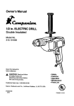
Operator's Manual
Companion
A
GENUINE
SEARS
PRODUCT
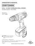
318 in. (10 mm) CORDLESS
Variable Speed / Reversible
DRILL-DRIVER
Model Nos.
315.101810 - 9.6 Volt
315.101820 - 12 Volt
Ryobi
Save this manual for
future reference
A
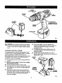
WARNING:
•
•
•
•
•
Torgduee
theAskof
injury, the user must read and understand
the operator's manual before using this
product,
Customer
Help Lfne: 1-800-932-3188
Sears, Roebuck and Co., 3333 Beverly
Rd., Hoffman
visit the Craftsman web page: www.sears.com/craftsman
983000-231
4-03
Estates,
IL 60179
USA
Safe;y
Features
Operation
Maintenance
Parts List
•
General Safety Rules .................................................................................................................................................
3-4
•
Specific Safety Rules ..................................................................................................................................................
4-5
•
Symbols ..........................................................................................................................................................................
6
•
Specifications
7
•
Features
•
Operation ..................................................................................................................................................................
•
Maintenance
•
Exploded View and Repair Parts List ...........................................................................................................................
17
•
Parts Ordering / Service ...............................................................................................................................................
18
.................................................................................................................................................................
.....................................................................................................................................................................
.................................................................................................
FULL ONE YEAR WARRANTY
ON COMPANION
CORDLESS
7-8
8-14
_...............................................................
15
3/8 In. DRILL-DRIVER
If this Sears Dril_-Driver fails to gLve complete satisfaction within one year from the date of purchase, RETURN IT TO
THE NEAREST SEARS STORE OR SEARS SERVICE CENTER IN THE UNITED STATES, and Sears will replace it,
free of charge.
If this Sears Cordless
the date of purchase.
Drill-Driver
is used for commercial
or rental purposes,
this warranty applies for only 90 days from
This warranty gives you specific lega_ righ!s, and you may i also have other rights which vary from state to state.
Sears, Roebuck and CO., Dept. 817 WA, Hofhnan Estates, IL 60179
Your cordless drill-driver has many features for making
the use of this product more pleasant and enjoyable.
Safety, performance, and dependability have been
given top priority in the design of this product making it
easy to maintain and operate.
_,
_k
Look for this symbol to point out important
attention]!t
Your safety is involved.
WARNING:
Do not attempt to use this product
until you read thoroughlyand understand completely
the operator'smanual. Pay c{oseattention to the
safety rules, Inc/udJngDangers, Warnings, and
Cautions. If you use this productpropedyand only
as intended, you wiif enjoy years of safe, reliable
service.
safety
precautions.
It means
WARNING:
The operation of any drtlt can result In foreign objects being thJ'own into your eyes, which can
result in severe eye damage. Before beginning power tool operation, always wear safety goggles
or safety glasses with side shields and a full face shield when needed. We recommend Wide
Vision Safety Mask for use over eyeglasses or standard safety glasses with side shields. Always
wear eye protection which is marked to comply with ANSI Z87.1.
2
_k
Read end understand all InstnucWARNING:
lions. Failure to follow all instructions (isled below,
may result in electric shock, fire and[or serious
personal injury.
[]
Remove adjusting keys or wrenches before turnIng the tool on. A wrench or a I(ey that is left attached
to a rotating part of the tool may result in personal
injury.
Im DO not overreach. Keep proper tooting and balance at all times, Proper (ootthg and betarme enabte
better control of the tool in unexpected situations, Do
not use on a ladder or unstable support
SAVE THESE INSTRUCTIONS
WORKAREA
[]
Keep your work area clean and well lit. Cluttered
benches and dark areas inviteaccidents,
[]
m
Do _tot operate power tools in explosive atmospheres, such as in the presence of flammable
[iduids, gases, or dust. Power tools create sparks
which may ignite tlqe dust or t'umes.
TOOL USE AND CARE
[]
11 Use clamps or other practical way to secure and
support the workpleee to smbte
platform. Holding
the work by hand or against your body is unstable and
may lead to loss of control.
[] Do not force tool. Use the contact tool for your
application. The correct tool wilt do the job better and
safer at the rate for which it is designed.
[] Do not use tool If switch does not turn it on or off. A
tool that cannot be controlled with the switch is dangerous and must. be repaired.
[] Disconnect battery pack from tool or place the
switch In the Iocksd on or off posi|Jon bBfore
making any ed|tmtmenta, changing accessories, or
storing the tool. Such preventive safety measures
reduce risk of starting the tool accidentally.
[] Store idle tools out of reach of children end other
untrained persons. Tools are dangerous in the hands
of untrained users.
Keep bystanders, children, and visitors away while
operating a power too{. Distractions can cause you
to lose control
ELECTRICAL
SAFETY
Do not abuse the cord. Never use the cord to carry
the charger. Keep cord away from heat, oil, sharp
edges, or moving parts. Replace damaged cords
immediately. Damaged cords may create a fire.
m
A battery operated tool with Integral batteries or a
separate battery pack must be recharged only
the specified charger for the battery A charger _at,
may be suitable for one type of battery may create a
risk Of fire when used with another battery. Use battery
only with charger tiered.
MODEL
315.101810
315.101820
!
BATTERY PACK
1312238
1312239
CHARGER
1420920
1420921
[]
Use battery operated tool only with specifically
designated
battery pack. Use of any other batteries
may create a risk of fire. Use only with battery pack
listed.
PERSONALSAFETY
•
[]
[]
Use safety equipment. Always wear eye protection.
Dust mask, nonskid safety shoes, hard hat, or hearing
protection must be used for appropriate conditions.
•
Stay alert, watch what you are doing and use
common sense when operating a power toot. Do
not use tool while tired or under the influence of
drugs, alcoho{, or medication. A moment of inattention wh(ie operating power tools may result in serious
personal injury.
•
Dress proper|y. Do not wear loose clothing or
JeweEry. Contain long hair. Keep your hair, ctot_ng_
and gloves away from moving parts. Loose clothes,
jewelry, or long hair can be caught in moving parts.
•
Avoid accidental starting. Be sure switch Is in the
locked or off position before inserting beffery
pack. Carrying tools with your finger on the switch or
inserting the battery pack into a tool with the switch on,
invites accidents.
•
3
When battery pack is not in use, keep it away from
other metal objects like: paper clips, coins, keys,
naJl_ screws, or oif_r small metal objects that can
make a connection from one terminal to another.
Shorting the battery terminals together may cause
sparks, burns, or a fire.
Maintain tools with care. Keep cutting tools sharp
and clean. Properly maintained tools, with sharp
ca_ting edges are less likely to bind and are easier to
control,
Check for misaUgnment or binding of moving parts,
breakage of parts, and any other condition that may
affect the tool's operation, if damaged, have the toot
serviced before using. Many accidents are caused by
poorly maintained tobis.
Use only accessoHea that ere recommended
by the
manufacturer
for your model. Accessories that may
be suitable for one tool, may create a risk of iniury when
used on another tool.
Keep the tool and its handle dry, clean and free
from oil and grease. Always use a clean cloth when
cleaning, t-4ever use brake flu(de, geanline, petroleumbased products, or any strong solvents to clean your
tool.
•
SERVICE
•
Tool service must be performed only by qualified
repair personnel. Service or maintenance performed
by unqualified personnel could result in a risk of injury.
When servicing a toot, use only identical replacement parts. Follow Instructions in the Maintenance
sect|on of this manual. Use of unauthorizedparts or
failure to fallow Maintenance instructionsmay create a
r_skof shockor injury.
I-IoId tool by insulated gripping surfaces when performing an operation where the cuffing tool may contact
hidden wiring, Contact with a "live" wire will make exposed metal parts of the tool "live" and shock the operator.
ADDITIONAL
•
•
•
Know your power tool, Read operator's manual
cerefuiiy. Learn its applications and limitations,
as
wail as the specific potential hazards related to
this tool Following this rule will reduce the risk ot
electric shock, fire, or serious iniury.
Do not charge battery tool in a damp or wet location. Following this rule will reduce the risk of electric
shock.
•
Always wear safety glasses with side shields.
Everyday glasses have only impact resistant lenses.
They are NOT safety glasses.
For heat results, your battery tool should be
chmged _n a locetlonwhere the tempera_ro is more
than 50_F but less than 100_F. Do not store outside
or tn vehlclss.
•
Under extreme usage or temperature conditions,
battery leakage may occur. If Ilqutd comes in
contact with your skin, wash Immediately
with
soap and water, men neutralize with lemon juice or
vinegar. If liquid gets Into your eyes, flush them
with clean water for at )east 10 minutes, then see}(
immediate medical attention. Following this rule will
reduce the risk of serious personal injury.
•
Avoid body contact with grounded
surfaces, such
as pipes, radiators, reagan, aired,refrigerators.
There is an increased risk of electric shock if your
body Is grounded.
•
Don't expose power tools to rain or wet conditions. Water entering a power fool will increase the
risk of elecVlc shock,
IMPORTANT
•
•
RULES FOR SAFE OPERATION
RULES
FOR
BATTERY
TOOLS
Battery tools do not have to be plugged Into an
aiactrfcal outlet; therefore, they are always tn
operating condition. Be aware of possible hazards
when not using your battery tool or when changIng accessories. Following this rule wiII reduce thl_
risk of electric shock, fire, or serious personal iniury.
Do not place battery tools or their batteries near
_ire or heat. This will reduce the risk of explosion and
possibly injury,
,&WARNING:
Batteries vent hydrogen gas and can
explode in the presence of a source of ignition,such
as a pilot bight.To reduce the risk of serious personal
injury,never use any cordless product in the presence
of open flame. An expLed,
ed bat_e_ carl propel debris
and chemicals. If exposed, flush with water immediately.
4
_li
[]
WARNING:
Never use a battery that has been
dropped or received a sharp blow. A damaged
battery is subject to explosion. Properly dispose of a
dropped battery immediately.
Failure to heed this
warning can result in serious personal injury.
Before using battery charger, read all instructions
and cautionary markings in this manual, on
battery charger, and product using battery
charger. Following this rule will reduce the risk oil
electdc shock, fire, or sedous persona] injury.
•
To reduce risk of injury, charge only nickelcadmium type rechargeabia batteries. Other types
of batteries may burst causing personal Injury and
damage. Following this rule will reduce the risk of
electric shock, fire, or serious personal injury.
[]
Do not expose charger to wet or damp conditions.
Following this rule will reduce the risk of electric
shock, fire, or serious personal injury.
[]
Use of an attachment
not recommended or sold by
the battery charger manufacturer
may result In a
risk of fire, electric shock, or injury to persons.
Following this rule will reduce the risk of electric
shock, fire, or serious personal injury.
[]
[]
To reduce risk of damage to charger body and
cord, pull by charger plug rather than cord when
disconnecting charger. Following this rule wili
reduce the risk of electric shock, fire, or sedous
personal injury.
_1,
Make sure cord Is located so that it will not be
stepped on, tripped over, or otherwise subjected
to damage or stress. Following this rule will reduce
the risk of serious personal injury.
[]
Do not operate charger with a damsged cord or
plug. If damaged, have replaced Immediately
by a
qualified serviceman.
Following this rule will reduce
the risk or electric shock, fire, or serious personal
injury.
[]
Do not operate charger if It has received a sharp
blow, been dropped, or otherwise damaged in any
way; take II to a qualified serviceman. Following this
rule will reduce the risk of electric shock, fire, or
serious personal injury.
m
Do not disassemble charger; take it to a qualified
serviceman
when service or repair Is required.
Incorrect rea_mbly
may result in a risk of electric shock or fire. Following thls rule will reduce the
risk of electric shock, fire, or serious personal injury.
[]
TO reduce the risk of electric shock, unplug
charger from outlet before attempting any maintenance or cleaning. Turning off controls will not
reduce this risk. Following this rule will reduce the
risk of electric shock, fire, or serious personal injury.
[]
Disconnect charger from power supply when not
In use. Following this rule will reduce the risk of
electric shock, fire, or serious personal Inlury.
[]
Save these Instructions, Refer to them frequently
and u_e them to Instruct others who may use thia
tool. If you loan someone this toot, loan them
these instructions
also, Following this rule wilt
reduce the risk of electric shock, fire, or serious
personal tnlury.
_1_ WARNING:
Some dust created by power sanding,
sewing, gfmd)ng, drill)ng, and other construction
activildes cOntains chemicals known to cause cancan,
birth defects or other reprodu_'tive harm. Some
examples of these chemicals are:
[]
Be not abuse cord. Never carry tool by cord or
yank it to disconnect from receptacle. Keep cord
from heat, all and sharp edges. Following this rule
will reduce the risk of eJectdc shock or fire.
•
An extension cord should not be used unless
absolutely necessary.
Use of improper extension
cord could result in a dsk of fire and electric shock. If
extension cord must be used, make sure:
• crystalline sitloa from bricks and cement and
other masonry products, and
a. That pins on plug of extension cord are the
same number, size and shape as those of
plug on charger.
Your nsk from these exposures varies, depending
on how often you do this type of work, To reduce
your exposure to these chemicals: work in a well
ventilated area, and work with approveO safety
equipment, such as those dust masks that are
sperJally designed to filter out microscopic particles.
b. That exlenslon cord is properly wired and In
good electrical cond_on; and
c. That wire size is large enough for AC ampere
ra_:ingof charger as specified below:
Cord Length (Feet)
25'
50'
100'
Cord Size (AWG)
_6
16
16
Note'. AWG = American Wire Gage
• lead item lead-based
paints,
• arsenic and chromium from chemically-treated
lumber.
Important: Some of the following symbols may be used on your tool. Please study them and learn their meaning.
interpretation of these symbols will allow you to operate the tool better and safer.
SYMBOL
NAME
DESIGNATION/EXPLANATION
V
Volts
Voltage
A
Amperes
Current
Hz
Hertz
Frequency
mi_
Minutes
Proper
(cycles per second)
Time
II
"_
Alternating
Current
Type or a oharactedatic of current
Direct Current
Type or a characteristic of current
no
No Load Speed
Rotational speed, at no load
..Jmtn
Revolutions or Reciproca_on PeT Minute
Revolutions, strokes,
surface speed, orbits etc. per minute
Safety Alert Symbol
Indicates
It means attentiontH
danger, warning
Your or
safety
caution.
is
Involved.
Wear Eye Protection
safety
with side
shields
Alwaysglasses
wear safety
goggles
or when
operating this product.
,_
Q
Wet Cond_ons Alert
Do not expose to rain or use in damp
locations.
T,he purpose of safety symbols is to attract your attention to possible dangers. The safety symbols, and the
explanations with them, deserve your careful attention and understanding. The safety warnings do not by themselves
eliminate any danger. The instructions or warnings they give are not substitutes for proper accident prevention
measures.
Symbol
A
Meaning
DANGER: Indicates an Imminentlyhazardous situationwhich, If not avoided, will result In death or
serious injury.
WARNING:
Indicates a potentially hazardous situation which, if not avoided, could result in death or
serious injury.
A
NOTE:
CAU_TION: Indicates a potentiallyhazardous situation which, if not avoided, may result in minor or
moderate Injury. It may also be used to alert against unsafe practicesthat may cause propertydamage.
' t1' I
i
Advisesyou of informationor instructionsvital to the operationor maintenance of the equipment.
SAVE THESE INSTRUCTIONS
6
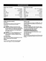
MODELNO.315.101810
Chuck ...........................................
MODEL NO. 315.101820
318 in. (tO mm) Keyless
Motor ................................................................
Switch .......................................................
9.6 Volt DC
Variable Speed
Gear Train .............................................................
1 Speed
Chuck ...........................................
3/8 in. (10 mm} Keyless
Motor .................................................................
12 Volt DC
Switch .......................................................
Variable Speed
Gear Train .............................................................
1 Speed
No Load Speed .................................................
0-550/rain.
No Load Speed .................................................
0-550/min.
Clutch ...............................................................
4 Positions
Clutch ...............................................................
4 Positions
Charger input .................................
120 V. 60 Hz, AC only
Charge Rate .......................................................
3-6 Hours
Charger Input .................................
Torque .....................................................................
Torque .....................................................................
80 in.lb
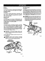
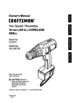
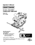
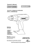
KNOW YOUR DRILL-DRIVER
See Figure 1.
Before attempting to use your drill-driver, familiarize
yourself with all operafing features and safety
requirements.
,_
WARNING:
Carefully read through this entire
operator's manual before using your new drill-driver.
Pay close attention to all Safety Rules, Warnings and
Cautions. If you use your drill-driver property end
only for what it is intended, you will enjoy years of
safe, reliable service.
120 V. 60 Hz, AC only
Charge Rate .......................................................
SWITCH
3-6 Hours
90 in.lb
LOCK
The switch trigger can be locked in the OFF position. This
feature helps reduce the possibility of accldentaJ starting
when not in use.
VARIABLE
SPEED
This tool has a variable speed switch that delivers higher
speed with Increased tdgger pressure. Speed is controlled
by the amount of switch trigger depression.
FORWARD/REVERSE
{DIRECTION
SELECTOR
OF ROTATION
SELECTOR)
Your drill-driver has a forwardlreverse selector located
,_
WARNING: Do not allow familiaritywith your dditdriver to make you careless. Remember that a
careless fraction of a second is sufficientto inflict
severe injury.
KEYLESS CHUCK
Yourdrill-driverhas a keylesschuckthat allows you to hand
tighten or release ddUbit In the chuckjaws.
SWITCH
To turn your drill-driver ON, depress the switchtrigger.
Release switchtriggerto turn your drill-driverOFF.
a_ve
the switch _iggar.
Bff STORAGE
When not in use, bits provided with your drill-driver can be
placed in the storage area located on the top of the motor
housing.
TORQUE
ADJUSTMENT
R)HG
KEYL_SS
CHUCK
BIT
STORAGE
CHARGER
ASSEMBLY
_,
ROTATION
SELEGTOR
WARNING:
If any parts are missing, do not operate
this tool until the missing paris are replaced. Failure
to do so could result in possible serious personal
iniury.
•
[]
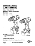
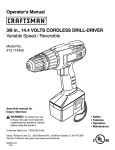
CHARGING
YOUR DRILL-DRIVER
The battery pack for this tool has been shipped In a low
charge condition to prevent possibte problems. Theref_re,_
you should charge it at least 6 hours prior to use.
Note: Batteries will not reach full charge the first time they
are charged. Allow several cycles (drilling followed by
recharging} for them to ful{y charge.
•
Charge battery pack only with the charging
provided.
•
Make sure power supply is normal
120 volts, 60 Hz, AC only.
•
Connect charging assembly to power supply.
•
Piece battery pack in charging assembly. Align raised
rib on battery pack with groove in charging assembly.
See Figure 2.
Press down on battery pack to be sure contacts on
battery pack engage properly with contacts in charging assembly. When properly connected, red light will
turn on and remain on unt"rl ba_.'_eryis removed or
charger is unp(ugged.
•
Ill
After normal usage, 3 hours of charging time is
required to be fully charged. A minimum charge time
of 6 hours is required to recharge a completely
discharged battery,
The battery pack will become slightly warm to the
touch wht/e aharg|ng. This is normal and does not
indicate a problem.
DO NOT place charging assembly in an area of
extreme heat or cold. It will work best at temperatures
between 50°F-IOO°F.
BA'n'ERY
PACK
assembly
house voltage,
CHARGE
INDICATOR
LIGHT(LED)
CHARGING
Fig, 2
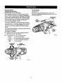
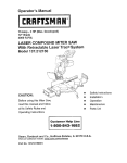
TOINSTALLBATrERYPACK
TO REMOVE BATTERY PACK
[]
Lock switch trigger on your drill by pla¢ir_ the direction
of rotation selector In center position, See Figure 3.
[]
•
Place the battery pack in your ddlL Align raised rib on
battery pack with groove in drips battery port. See
Figure 4.
[]
•
•
Make sure the latches on each side of your battery
pack snap in place and that battery pack is secured in
drill before beginning operation.
,I_
Lock switch trigger on your drill by placing the direction
of rotation selector in canter position. See Figure 3.
Locate latches on side of battery pack and depress both
sides to release battery pack from your ddlt. See Figure 4.
Remove battery pack from your drill.
CAU'rLON: When pLe,c_ng battery pack in your dr_tL,
be sure raised rib on baL'tery pack atig,ns wLth groove
in dnU's battery pert and latches snap in pLace
propedy, Improper assembly of battery pack can
cause damage to Internal components.
DIRECTION OF
ROTATIONSELECTOR
_FORWARD/ REVERSE)
BATTERY
PACK
CEN'rER POSITION
(LOCK)
BATTERY
PORT
SWITCH TRIGGER
Fig. 3
LATCHES
DEPRESSLATCHES
TO
RELEASE
BATTERYPACK
Fig. 4
9
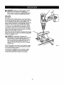
SWITCH
KEYLESS
See Figure 5.
See Figure 6.
Your drill starts and stops by depressing and releasing the
switch trigger. Release the switch tdgger to turn ddll OFF.
A keyless chuck has been provided with your drill to allow for
easy installation and removal of bits, As the name implies,
you can hand tighten or release drill bits in the chuck jaws.
Grasp and hold the collar of the chuck with one hand. Rotate
the chuck body with your other hand. The arrows on the
chuck indicate which direction to rotate the chuck body in
order to GRIP (tighten) or RELEASE (unlock) the drill bit.
VARIABLE
SPEED
See Figure 5.
Your drill has a variable speed feature in the switch. The
switch delivers higher speed and torque with increased
trigger pressure, Speed is controlled by the amount of
switch trigger depression.
SWITCH LOCK
See Figure 5.
The switch trigger can be locked in the OFF position.This
feature helps reduce the possibilityof accidental starting
when not inuse. To ldck the switchtdgger,place the direction
of rotaUanselector in the center position.
CHUCK
_lb WARNING. Do not hold the chuck body with oae
hand and use the power of the drillto tighten chuck
Jaws on drill bits.Chuck bodycould slip Jnyourhand
or your band could slip and come in contact with
rotatingdrillbit.This couldcause an accidentresulting
in sedous persona) injury.
RELEASE
(UNLOCK)
REVERSIBLE
CHUCKBODY
See Figure 5.
This tool is reversible, The direction of rotation is controlled
by a selector located above the switch trigger. With the drill
held in normal operating position, the direction of rotation
setector should be positioned to the tett of the swrtq_ for
dritling, The drilling direction is reversed when the selector is
to the right of the switch. When the selector is in center
position, the switch tdgger is locked.
,_
GRIP
(_GHT£R)
CAUTION: To prevent gear damage, always allow
chuck to come to a completestop before changingthe
directionof rotation.
CHUCK COLLAR
To stop, relea.seswitchtrigger and allow the chuck to come
to a complete stop.
Fig: 6
_
WARN|NG:
Battery tools are atways in operating
condition. Therefore, switch should always be locked
when not In use or when carrying at your side.
DIRECTIONOF
ROTATIONSELECTOR
(FORWARD/ REVERSE)
REVERSE
!
CE_'ER POSITION
(LOCK)
FORWARD
SWITCHTRIGGER
Fig. 5
tO
INSTALLING
BITS
I
Place the direction of rotation selector in center position.
See Figure 3. This will turn oft the power to your drill.
•
Open or close the chuck jaws to a point where the
opening is stlghtly larger than the bit size you intan0 to
use. Also, raise the ('ront ot your drill slightly to kee_, the
bit froro falling out of the chuck jaws.
I
REMOVING
BITS
See Figure 7.
•
Ptace the direction of rotation selector in center
•
/I
To loosen: grasp and hold the collar of the chuck with
one hand, while rotating chuck body with your other
hand.
Note: Rotate chuck body in the direction of the arrow
marked RELEASE to loosen chuck jaws.
•
DO NOT use a wranch to t_hten or _:;osen the chu_ck
]_ws.
Remove drill bit from chuck iaws.
{nser_ your dri(1 bit Into the chuck the full length of the
jaws. See Figure 7,
RELEASE
(UNLOCK)
CHUCK BODY
•
BIT
CHUCK COLLAR
•
Tighten the chuck jaws on the drill bit. To tighten, grasp
and hold the collar of the chuck with one hand, while
rotating the chuck body with your other hand.
Note: Rotate the chuck body in the direction of the arrow
marked GRIP to tighten the chuck jaws. DO Nor use a
wrench to tighten or loosen the chuck jaws.
,l_
position. See Figure 3. This wi(l turn off the power to
your drill.
Loosen the chuck jaws from drill bit.
WARN|NG;
Do not insert drill bit into chuck jaws and
tighten as shown in Figure 8. This could cause drill bit
to be thrown from drill resulting in possible serious
personal injury or damage to the chuck.
Fig. 8
11
SCREWDRIVING
BIT STORAGE
TORQUE
See Figure 10.
ADJUSTMENT
(Driving power of your drill-driver)
When using your drill-driver for various driving applications, it becomes necessary to increase or decrease the
torque in order to help prevent the possibility of damaging
screw heads, threads, workpiece, etc. In genera/, torc_e
should correspond to the intensity of the screw diamefer.
If the torque is too high or the screws too small, the
screws may be damaged or broken.
When not in use, bits provided with your drill can be
placed in the storage area located on the top of your drill
as shown in figure 10.
SCREWDRWER
BRS
The torque '=sadjusted by rotating the torque adiustment
ring. See Figure 9. The torque is greater when the torque
adjustment ring is set on a higher setting. The torque is
less when the torque adjustment ring is set on a lower
setting.
The proper seIting depends on the type of material and the
size of screw you are using.
TO ADJUST
BIT
STORAGE
AREA
TORQUE
Identify the four torque indicator settings located on
the front of your drill. See Figure 9.
Fig. t 0
Rotate adjustment dng to the desired setting,
•
Position %': For dri_ng small screws.
•
Position 2 :
For tidying screws into soft maten;a/
Position 3 :
For ddving screws into hard wood
Will#
For heavy drilling
TO DECREASE
TORQU_
TO INCREASE
TORQUE
TORQUE
ADJUSTMENTRING
Fig. 9
12
,_l
WARN|NG:
Always wear safety goggles or safety
glasses with side shields when operating tool.
Failure to do so could result in objects being thrown
into your eyes, resulting in possible serious injury.
DRILLING
See Figure 11.
When drilling hard, smooth surfaces, use a center punch
to mark the desired hole location. This wit( prevent the drill
bit from slipping off center as the hole is started. However, the lower speed feature allows starting holes without
center punching if desired. To accompJish this, simply
operate your driit at lower speed until the hole is started.
The mateClal to be drilled should be secured in a vise or
with clamps to keep it from turning as the ddll bit rotates.
Hold tool firmly and place the bit at the point to be drilled.
Depress the switch trigger tO start tool.
Move the drill bit into the workplace, applying only enough
pressure to keep the bit cutting. Do not force or apply side
pressure to elongate a hole.
_1
WARN|NG:
Be prepared for binding or tYt
breakthrough. When these situations occur, the drill
has a tendency to grab and kick opposite to the
direction of rotation and could cause loss of controi
when breaking through matedaL If you are not
prepared, this loss of control can result in possib_
sedous injury.
When drilling metals, use a light oil on the drill bit to keep
It from overheating. The oil will prolong the life of the bit
and increase the drilling action.
Fig. 11
If the bit jams in workpiece or if the drill stalls, release
switch trigger immediately. Remove the bit from the
workplace and determine the reason for jamming.
13
CHUCK
REMOVAL
See Figures
•
Lock the switch trigger by placing the direction of rotation
selector in center position. See Figure 3.
[]
Insert a 5/16 inch or larger hex key into the chuck of
your ddtt and tighten the chuck Jaws securely.
•
Tap the hex key sharply with a mallet in a clockwise
direction. See Figure 12. This will loosen the screw in
the chuck for easy removal.
•
Insert hex key in chuck and tighten chuck jaws securely.
Tap sharply with a mallet in a counterclockwise direction.
This will loosen chuck on the spindle. It can now be
unscrewed by hand,. See Figure 14.
12, 13, and 14.
Open chuck jaws and remove hex key. Remove the
chuck screw by turning it in a clockwise direction. See
Figure 13.
Note: The screw has left hand threads.
TO RETIGHTEN A LOOSE CHUCK
The chuck may become loose on spfndle and develop a
wobble. PariodlcaJly check the chuck screw for tightness,
To tighten,follow these steps:
[] Lockthe switchtriggerby placingthe directionof rotation
selector in center position.See FTgure3.
•
[]
Open the chuck jaws,
Insert hex'key into chuck and tighten chuck jaws
securely.Tap hex key sharplywith a malletIn a clockwise
direction. This willtighten chuck on the sl_indle.
•
Ill
Open th.echuck jaws and remove tmx key.
Tighten the chuck screw.
Note: The chuck screw has left hand threads.
MALLET
HEXKEY
K£YLESS
CHUCK
F_j.74
Fig. 13
_4
,l_
Do not abuse power tools. Abusive practices can damage
tool as well as workptece.
WARNING:
When servicing,
use only Identica(
Sears replacement parts. Use of any other part may
create a hazard or cause product damage.
Only the parts shown on parts list, page 16, are intended
to be repaired or replaced by the customer. All other parts
should be replaced at a Sears Serv%ceCenter.
Avoid using solvents when cleaning plastic pads. Most
_astics are susceptible to damage from various types of
commercial solvents and may be damaged by their use.
Use clean cloths to remove dirt, dust, o11,grease, etc.
,_
_k
WARNING:
Do not at any time let brake f_uids,
gasoline, petroleum-based
products, penetratingloilsl
etc. come in contact with p[asttc parts. They contain
chemicals that can damage, weaken or destroy
plastic.
WARNING:
Do not attempt to modify this tool or
create accessories not recommended for use with
this toot. Any such alteration or modification is
misuse and could result in a hazardous condition
leadlr_j to possible ssdous personal injury.
BATTERIES
The battery pack for your drill-driver is equipped with
nickel-cadmium rechargeabie batteries. Length ot service
from each charging will depend on the type of work you
are doing.
The batteries In this too_ have been designed to provide
maximum trouble free life. However, like all batteries, they
will eventually wear out. DO not disassemble battery pack
and attempt to replace the batteries. Handling of these
batteries, especially when wearing rings and |ewelry,
could result in a serious burn.
•
Store and charge your batteries in a cool area.
Temperatures below 50°F or above 100°F will shorten
battery life.
•
Never store batteries in a discharged condition.
Recharge them Immediately after they are
discharged.
•
All batteries gradually lose their charge. The higher
the temperature the quicker they lose their charge, if
you store your tool for long periods of time without
using it, recharge the batteries every month or two.
This practice will prolong battery life.
To obtain the longest possiblebattery life, we suggestthe
following:
To preserve nalural resources, please
recycle or dispose of batteries property.
This product contains nickel-cadmium
batteries. Local, state or federal laws
may prohibit disposal of nickel-cadmium
batteries in ordinary trash.
BATTERY PACK REMOVAL
FOR RECYCLING
A
Consult your local waste authority for information
regardingavailable recyclingand/or disposal options.
15
AND PREPARATION
WARNING:
Upon removal, cover the battery pack's
terminals with heavy duty adhesive tape. Do not
attempt to destroy or disassemble battery pack or
remove any of its components. N_ckeE-cadmium
batteries must be recycled or disposed of properly.
Also, never touch both terminals with metal objects
and/or body parts as short circuit may result. Keep
away from children. Failure to comply with these
warnings could result in fire and/or serious injury.
16
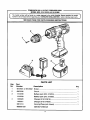
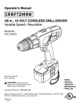
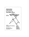
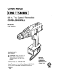
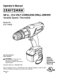
COMPANION 9.6 & 12 VOLT CORDLESS DRILL
MODEL NOS. 315.101810 & 315.101820
[
1
The model number will be found on a plate attached to the motor housing. Always mention the model
number in all correspondence regarding your CORDLESS DRILL-DRIVER or when ordering repair parts.
SEE BACK PAGE FOR PARTS ORDERING
INSTRUCTIONS
i=l=
i=
2
4
PARTS LIST
Key
No.
Part
Number
1
6612001
2
3
4
Description
or 6612002
Qty.
Screw .................................................................................
1
6903336
Chuck .................................................................................
t
1312238
Battery pack (315.t01810)
.................................................
1
1312239
Battery pack (315.101820)
.................................................
1
1420920
Charger
(315.101810)
........................................................
1
1420921
Charger
(315.101820)
........................................................
1
5801314
Carrying'Case
983000-231
Operator's
(not shown)
Manual
_7
................................................
1
Your Home
For repair-in
your home-of all major brand appliances,
lawn and garden equipment, or heating and cooling systems,
no matter who made it, no matter who sold it!
For the replacement parts, accessories and
owner's manuals that you need to do-it-yourself.
For Sears professional'inStallation
of home appliances
and items like garage door openers and water heaters.
1-800-4-MY-HOME
Call anytime,
®
(1-800-469-4663)
day or night (U.S.A.
www.sears,com
and Canada)
www.sears,ca
Our Home
For repair of carry-in items like vacuums, lawn equipment,
and electronics, call or go on-line for the location of your nearest
Sears Parts & Repair Center,
1-800-488-1222
Call anytime,
day or night (U.S.A.
only)
www.sears.com
To purchase a protection agreement (U.S.A.)
or maintenance agreement (Canada) on a product serviced
1-800-827-6655
(U.S.A.)
Para pedir servicio de reparacibn
1-800-361-6665
Au Canada
a domicitio, y para ordenar piezas:
1-888-SU-HOGAR
(1-888-784-6427)
_
sE, s
by Sears:
(Canada)
pour service en fran_ais:
1.800.LE.FOYEI_C
(1-800-533-6937)
www.sears.ca
® Registered Trademark / TMTredem ark / SMSewlce M ark of Sears, Roebuck and Co.
® Marc= Registrada / TM Marca de F_brica / SMMares de Sewicio de Sears, Roebuck and Co,
MCMarque de corn merce ! MDMarque d*'_posde de Sears, Roebuck and Co.
O Sears, Roebuck and Co.