1
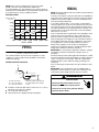
INSTALLATION INSTRUCTIONS FOR
PACKAGE HEAT PUMP OR PACKAGE COOLING UNIT
ATTENTION INSTALLATION PERSONNEL
Prior to installation, thoroughly familiarize yourself with this installation manual. Observe all safety warnings.
During installation or repair, caution is to be observed.
It is your responsibility to install the product safely and to educate the customer on its safe use.
Placeholder
for Bar Code
Keep this literature in a safe place for future reference.
Whirlpool Gold® Models
WGPH45**AM, WPC45**AM
WPIO-394
These installation instructions cover the outdoor installation of
self-contained package air conditioner and heating units. See the
Specification Sheets applicable to your model for information
regarding accessories.
NOTE: Please contact your distributor or our website for the
applicable Specification Sheets referred to in this manual.
Tradewinds Distributing Company, LLC
14610 Breakers Drive
Jacksonville, FL 32258
TABLE OF CONTENTS
HEAT PUMP/ELECTRIC COOLING SAFETY...............................2
TO THE INSTALLER.......................................................................3
IMPORTANT NOTE TO THE OWNER REGARDING
PRODUCT WARRANTY.................................................................3
SHIPPING INSPECTION ................................................................3
REPLACEMENT PARTS ................................................................3
CODES AND REGULATIONS ........................................................4
EPA Regulations...........................................................................4
National Codes.............................................................................4
MAJOR COMPONENTS ................................................................4
PREINSTALLATION CHECKS.......................................................4
Clearances and Accessibility .......................................................4
Unit Location ................................................................................4
Ground Level Preinstallation Details............................................4
Rooftop Preinstallation Details.....................................................5
Roof Curb Installations Only ........................................................5
Rigging Details .............................................................................5
Airflow Conversion .......................................................................6
Ductwork ......................................................................................6
Filters ............................................................................................6
PIPING .............................................................................................7
Connect Condensate Drain .........................................................7
WIRING............................................................................................7
High Voltage Wiring......................................................................8
Low Voltage Wiring ......................................................................8
Internal Wiring ..............................................................................8
START-UP, ADJUSTMENTS AND CHECKS................................8
Start-up Procedure and Checklist—Cooling Cycle.....................8
Start-up Procedure—Heat Pump ................................................9
Final System Checks....................................................................9
COMPONENTS...............................................................................9
Contactor......................................................................................9
Crankcase Heater.........................................................................9
Condenser Motor .........................................................................9
Compressor..................................................................................9
Contactor Relay............................................................................9
Defrost Control ...........................................................................10
Outdoor Thermostat...................................................................10
Reversing Valve Coil...................................................................10
Indoor Blower Motor ..................................................................10
HEAT PUMP OPERATION ...........................................................10
Cooling Cycle .............................................................................10
Heating Cycle .............................................................................10
Defrost Control ...........................................................................11
SUGGESTED FIELD TESTING/TROUBLESHOOTING..............11
AIRFLOW MEASUREMENT AND ADJUSTMENT .....................12
Airflow Adjustments for Indoor Blower Motor ...........................12
WGPH45 DIP SWITCH FUNCTIONS...........................................12
BLOWER PERFORMANCE DATA...............................................13
CHARGE VERIFICATION .............................................................16
EXPANSION VALVE (TXV) SYSTEM ...........................................17
Single Speed Application—WPC45...........................................17
2-Speed Application—WGPH45................................................17
Refrigerant Charge Check—Units with Fixed Orifice Devices ..17
ELECTRIC HEAT INSTALLATION AND ADJUSTMENT............17
SYSTEM MAINTENANCE ............................................................18
TROUBLESHOOTING CHART.....................................................19
APPENDIX .....................................................................................20
Wiring Diagram—WGPH45(24-43)AM.......................................20
Wiring Diagram—WGPH45(49-60)AM.......................................21
Wiring Diagram—WPC45**AM...................................................22
Product Dimensions...................................................................23
ASSISTANCE OR SERVICE .........................................................24
HEAT PUMP/ELECTRIC COOLING SAFETY
The following symbols and labels are used throughout this manual to indicate immediate or potential safety hazards. It is the owner’s
and installer’s responsibility to read and comply with all safety information and instructions accompanying these symbols. Failure to
heed safety information increases the risk of personal injury, property damage and/or product damage.
Recognize this symbol as a safety precaution.
WARNING
Hazards or unsafe practices could result in property
damage, product damage, severe personal injury or death.
Goodman 1
CAUTION
Hazards or unsafe practices may result in property
damage, product damage, personal injury or death.
CAUTION
Goodman 9
Hazards or unsafe practices may result in property
or product damage.
2
WARNING
Installation and repair of this unit should
be performed ONLY by individuals meeting
the requirements of an “Entry Level Technician,”
at a minimum, as specified by the Air-Conditioning,
Heating and Refrigeration Institute (AHRI). Attempting
to install or repair this unit without such background may
result in product damage, personal injury or death.
Goodman 7
WARNING
Do not connect
to or use any device
Goodman
36that is not design-
certified for use with this unit. Serious property damage,
personal injury, reduced unit performance and/or hazardous
conditions may result from the use of such non-approved
devices.
WARNING
Goodman
98
Connecting unit ductwork to unauthorized heat producing
devices such as a fireplace insert, stove, etc., may result
in property damage, fire, carbon monoxide poisoning,
explosion, personal injury or death.
WARNING
This product contains or produces a chemical or
chemicals which may cause serious illness or death and
which are known to the State of California to cause
cancer, birth defects or other reproductive harm.
Goodman 45
WARNING
HIGH VOLTAGE!
Goodman
6
Disconnect ALL power before servicing.
Multiple power sources may be present.
Failure to do so may cause property damage,
personal injury or death.
WARNING
This unit must not be used as a “construction heater”
Goodman 79
during the finishing phases of construction on a new
structure. This type of use may result in premature failure
of the unit due to extremely low return air temperatures
and exposure to corrosive or very dirty atmospheres.
WARNING
Goodman
37
To prevent the risk of property damage, personal injury, or
death, do not store combustible materials or use gasoline
or other flammable liquids or vapors in the vicinity of this
unit.
TO THE INSTALLER
Carefully read all instructions for the installation prior to installing
unit. Make sure each step or procedure is understood and any
special considerations are taken into account before starting
installation. Assemble all tools, hardware and supplies needed to
complete the installation. Some items may need to be purchased
locally.
After deciding where to install unit, closely look over the
location—both the inside and outside of the home. Note any
potential obstacles or problems that might be encountered as
noted in this manual. Choose a more suitable location if
necessary.
IMPORTANT NOTE: If a crankcase heater is used, the unit
should be energized 24 hours prior to compressor start-up to
ensure the crankcase heater has sufficiently warmed the
compressor. Compressor damage may occur if this step is not
followed.
IMPORTANT NOTE TO THE
OWNER REGARDING
PRODUCT WARRANTY
Your warranty certificate is supplied as a separate document with
the unit installed by your contractor. Read the limited warranty
certificate carefully to determine what is and is not covered. Keep
the warranty certificate in a safe place. If you are unable to locate
the warranty certificate, please contact your installing contractor,
or contact customer service at 1-866-944-7575 to obtain a copy.
To receive the 10-Year Parts Limited Warranty, online registration
must be completed within 60 days of installation. Online
registration is not required in California or Quebec.
Full warranty details and instructions are available at
www.whirlpoolhvac.com.
To register your unit, go to www.whirlpoolhvac.com. Click on the
manufacturer’s Comfort CommitmentTM Warranty link located at
the bottom center of the home page. Next, click on the Click
Here to Register Your Product link located at the top center of the
page, and complete the forms in the manner indicated.
SHIPPING INSPECTION
Upon receiving the unit, inspect it for damage from shipment.
Claims for damage, either shipping or concealed, should be filed
immediately with the shipping company. Check the unit model
number, specifications, electrical characteristics and accessories
to determine if they are correct. In the event an incorrect unit is
shipped, it must be returned to the supplier and must not be
installed. The manufacturer assumes no responsibility for
installation of incorrectly shipped units.
REPLACEMENT PARTS
When reporting shortages or damages, or ordering repair parts,
give the complete product model and serial numbers as stamped
on the product. Replacement parts for this product are available
through your contractor or local distributor. For the location of
your nearest distributor, consult the white business pages, the
yellow page section of the local telephone book or contact:
Tradewinds Distributing Company, LLC
14610 Breakers Drive
Jacksonville, Florida 32258
1-866-944-7575
If you are replacing an air handler, the system must be
manufacturer-approved and Air-Conditioning, Heating, and
Refrigeration Institute (AHRI) matched.
NOTE: Installation of unmatched systems is strongly
discouraged.
3
CODES AND REGULATIONS
The WPC/WGPH M-series air conditioners and heat pumps are
designed for outdoor use only. WGPH M-Series is available in
cooling capacities of 2, 2¹⁄₂, 3, 3¹⁄₂, 4 and 5 nominal tons of
cooling. WPC M-Series is available in cooling capacities of 2,
3 and 4 nominal tons of cooling. Optional field-installed heat kits
are available in 5, 8, 10, 15 and 20 kW. The units can be easily
installed in manufactured or modular homes with existing highstatic ductwork. The units can also be easily converted to
accommodate a plenum for normal or low-static applications.
The WPC/WGPH M-series are self-contained packaged units so
the only connections needed for installation are the supply and
return ducts, the line and low voltage wiring and drain
connection. The units are ETL listed and AHRI certified.
The information on the rating plate is in compliance with the FTC
and DOE rating for single-phase units. The efficiency ratings of
these units are a product of thermal efficiency determined under
continuous operating conditions independent of any installed
system.
EPA Regulations
IMPORTANT: The United States environmental protection
agency (EPA) has issued various regulations regarding the
introduction and disposal of refrigerants in this unit. Failure to
follow these regulations may harm the environment and can lead
to the imposition of substantial fines. Because regulations may
vary due to passage of new laws, we suggest a certified
technician perform any work done on this unit. Should you have
any questions, please contact the local office of the EPA.
National Codes
This product is designed and manufactured to permit installation
in accordance with National Codes. It is the installer’s
responsibility to install the product in accordance with National
Codes and/or prevailing local codes and regulations.
Clearances and Accessibility
The unit is designed to be located outside the building with
unobstructed condenser air inlet and discharge. Additionally, the
unit must be situated to permit access for service and
installation. Condenser air enters from 3 sides. Air discharges
upward from the top of the unit. Refrigerant gauge connections
are made on the right side of the unit as you face the compressor
compartment. Electrical connections can be made either on the
right, bottom or duct panel side of the unit. The best and most
common application is for the unit to be located 10" (25.4 cm)
from the wall (4" [10.2 cm]) minimum) with the connection side
facing the wall. Close to the wall application minimizes exposed
wiring.
Unit Location
Consider the affect of outdoor fan noise on conditioned space
and any adjacent occupied space. It is recommended that the
unit be placed so that the condenser air discharge does not blow
toward windows less than 25 ft (7.6 m) away. Consideration
should also be given to shade and unit appearance.
Heat pumps require special location consideration in areas of
heavy snow accumulation and/or areas with prolonged
continuous subfreezing temperatures. Heat pump unit bases
have holes under the outdoor coil to permit drainage of defrost
water accumulation. The unit must be situated to permit free
unobstructed drainage of the defrost water and ice. A minimum
2" (5 cm) clearance under the outdoor coil is required in the
milder climates.
Ground Level Preinstallation Details
The unit should be set on a solid, level foundation—preferably a
concrete slab at least 4" (10.2 cm) thick. The slab should be
above ground level and surrounded by a graveled area for good
drainage. Any slab used as a unit’s foundation should not adjoin
the building as it is possible that sound and vibration may be
transmitted to the structure.
Ground Level Installation
MAJOR COMPONENTS
The unit includes a hermetically sealed refrigerating system
(consisting of a compressor, condenser coil, evaporator coil with
flowrator), an indoor blower, a condenser fan and all necessary
internal electrical wiring. The heat pump also includes a reversing
valve, solenoid, defrost thermostat and control and loss of charge
protection. The system is factory-evacuated, charged and
performance tested. Refrigerant amount and type are indicated
on rating plate.
PREINSTALLATION CHECKS
Before attempting any installation, the following points should be
considered:
■ Structural strength of supporting members
■ Clearances and provision for servicing
■ Power supply and wiring
■ Air duct connections
■ Drain facilities and connections
■ Location may be on any 4 sides of a home, manufactured or
modular, to minimize noise.
4
A
B
D
C
C
B
A. 48" (121.9 m) minimum
B. 12" (30.5 cm) minimum
C. 36" (91.4 cm) minimum service clearance
D. 4" (10.2 cm) minimum
Roof Curb Installation
Rooftop Preinstallation Details
Ensure that the roof is weather tight and allows proper
drainage of condensation.
■ Use steel or treated wood beams as unit support for load
distribution.
NOTE: To ensure proper condensate drainage, unit must be
installed in a level position.
■ To avoid possible property damage or personal injury, the
roof must have sufficient structural strength to carry the
weight of the unit(s) and snow or water loads as required by
local codes. Consult a structural engineer to determine the
weight capabilities of the roof.
■ The unit may be installed directly on wood floors or on Class
A, Class B or Class C roof covering material.
■ To avoid possible personal injury, a safe, flat surface for
service personnel should be provided.
■
Rooftop Installation
Rigging Details
Roof Curb Installations Only
NOTE: Sufficient structural support must be determined prior to
locating and mounting the curb and package unit.
Curb insulation, cant strips, flashing and general roofing material
are furnished by the contractor.
Curbing must be installed in compliance with the National
Roofing Contractors Association Manual. Construct ductwork
using current industry guidelines. The ductwork must be placed
into the roof curb before mounting the package unit.
WARNING
To prevent property damage, the unit should remain in an
upright position during all rigging and moving operations.
To facilitate lifting and moving when a crane is used,
place the unit in an adequate cable sling.
WARNING
To prevent property damage, personal injury or death,
ensure the roof has sufficient structural strength to carry
the weight of the unit(s), roof curb, snow loads and water
loads as required by local codes. Consult a structural
engineer to determine the weight capabilities of the roof.
CAUTION
To avoid possible personal injury, a safe, flat surface for
service personnel should be provided.
5
IMPORTANT: If you are using bottom discharge with roof curb,
ductwork should be attached to the curb prior to installing the
unit. Lower unit carefully onto roof mounting curb. While rigging
unit, center of gravity will cause condenser end to be lower than
supply air end.
Rigging
Airflow Conversion
Units can easily be converted from horizontal to down-discharge
airflow delivery. In down-discharge or high-static installations, the
installer should measure the total external static and review the
blower performance charts before performing the installation. In
some installations, it will be necessary to change the blower
speed to provide proper airflow.
Ductwork
Duct systems and register sizes must be properly designed for
the C.F.M. and external static pressure rating of the unit.
Ductwork should be designed in accordance with the
recommended methods of Air Conditioning Contractors of
America Manual D (Residential) or Manual Q (Commercial).
All ductwork exposed to the outdoors must include a
weatherproof barrier and adequate insulation. A duct system
should be installed in accordance with Standards of the National
Board of Fire Underwriters for the Installation of Air Conditioning,
Warm Air Heating and Ventilating Systems. Pamphlets Number
90A and 90B.
The supply duct from the unit through a wall may be installed
without clearance. However, minimum unit clearances must be
maintained. The supply duct should be provided with an access
panel large enough to inspect the air chamber downstream of the
heat exchanger. A cover should be tightly attached to prevent air
leaks.
For duct flange dimensions on the unit, refer to the Unit
Dimension illustration in the Appendix.
For down-discharge applications, the ductwork should be
attached to the roof curb prior to installing the unit. Ductwork
dimensions are shown in the roof curb installation manual.
If desired, supply and return duct connections to the unit may be
made with flexible connections to reduce possible unit operating
sound transmission.
Filters
Horizontal Airflow
Single-phase models are shipped without horizontal duct covers.
If needed, these kits maybe ordered through the your local dealer
or see “Assistance and Service.”
Duct Cover Installations—Down-Discharge
CAUTION
To prevent property damage due to fire and loss of
equipment efficiency or equipment damage due to dust
and lint build up on internal parts, never operate unit
without an air filter installed in the return air system.
Remove the panels for down-discharge duct applications.
Filters are not provided with unit and must be supplied and
externally installed in the return duct system by the installer. An
optional factory-approved internal filter rack may also be used. A
field-installed filter grille is recommended for easy and
convenient access to the filters for periodic inspection and
cleaning. When installing filters, ensure the airflow arrows on the
filter are pointing toward the circulator blower.
Refer to the following unit filter size chart for filter size
information.
Minimum Filter Size
B
A
A. Supply air panel
B. Return air panel
Down-Discharge Applications
Cut insulation around bottom openings and remove panels from
the bottom of the unit, saving the screws holding the panels in
place.
NOTE: Down-discharge models require installation of horizontal
duct kit Number 20464501PDGK (medium chassis) and Number
20464502PDGK (large chassis).
6
Nominal Size—in. (cm)
Nominal Area—sq ft (cm2)
10 x 20 (25.4 x 50.8)
1.4 (1,301)
14 x 20 (35.6 x 50.8)
1.9 (1,765)
14 x 25 (35.6 x 63.5)
2.4 (2,230)
15 x 20 (38.1 x 50.8)
2.1 (1,951)
16 x 20 (40.6 x 50.8)
2.2 (2,044)
16 x 25 (40.6 x 63.5)
2.8 (2,601)
20 x 20 (50.8 x 50.8)
2.8 (2,601)
20 x 25 (50.8 x 63.5)
3.5 (3,252)
25 x 25 (63.5 x 63.5)
4.3 (3,995)
NOTE: Filters must have adequate face area for the rated
quantity of the unit. See the Air Delivery Table for the
recommended filter size. Size the filters in accordance with their
manufacturer recommendations. Throwaway filters must be sized
for a maximum face velocity of 300 ft per minute.
Air Delivery Table
Nominal Filter Area
sq ft (cm2)
7
(6,503)
6
(5,574)
5
(4,645)
4
(3,716)
3
(2,787)
2
(1,858)
Dis
500
p
bl
osa
eF
ilte
r
ilter
ent F
an
Perm
1,000 1,500 2,000 2,500
Airflow - SCFM
3,000 3,500
PIPING
Connect Condensate Drain
The condensate drain connection of the evaporator is a half
coupling of ³⁄₄" N.P.T. A trap must be provided to have proper
condensate drainage.
Condensate Drain Connection
A
F
E
D
A. Drain connection
B. 2" (5.1 cm) minimum
C. 3" (7.6 cm) minimum
■
■
■
WIRING
NOTE: All wiring should be made in accordance with the National
Electrical Code (N.E.C).
Consult your local power company to determine the availability of
sufficient power to operate the unit. Check the voltage, frequency
and phase at the power supply to ensure it corresponds to the
unit’s rated voltage requirement.
In accordance with the N.E.C. or local codes, install a branch
circuit fused disconnect near the unit. Determine wire sizes and
overcurrent protection from the unit nameplate ampacity and in
accordance with Branch Circuit Ampacity chart or the N.E.C. The
wiring should never be sized smaller than is recommended by
either of these 2 sources.
Fuses smaller than that recommended on the rating plate could
result in unnecessary fuse failure or service calls. The use of
protective devices of larger size than indicated could result in
extensive damage to the equipment. The manufacturer bears no
responsibility for damage caused to equipment as result of the
use of larger than is recommended size protective devices.
All units have undergone a run test prior to packaging for
shipment. This equipment has been started at minimum rated
voltage and checked for satisfactory operation.
IMPORTANT: Do not attempt to operate this unit if the voltage is
not within the minimum and maximum voltages shown on
nameplate.
All exterior wiring must be within approved weatherproof conduit.
The unit must be permanently grounded in accordance with local
codes, or in absence of local codes, with N.E.C. ANSI/ NFPA
Number 70-1984 or latest edition by using ground lug in the
control box.
Fuses or HACR type circuit breakers may be used where codes
permit.
IMPORTANT: Some single-phase units are equipped with a
single-pole contactor. Exercise caution when servicing as only
one leg of the power supply is broken with the contactor.
B
C
D. Positive liquid seal (required)
E. Flexible tubing, hose or pipe
F. Unit
Install the condensate drain trap as shown. Use a ³⁄₄" (1.9 cm)
NPT drain connection size or larger.
Do not operate without a trap.
Unit must be level or slightly inclined toward drain.
WARNING
Goodman 6HIGH VOLTAGE!
Disconnect ALL power before servicing.
Multiple power sources may be present.
Failure to do so may cause property damage,
personal injury or death.
7
■
High Voltage Wiring
■
■
From the unit disconnect to unit, the smallest wire size
allowable may be used for the ampacity, as the Disconnect
must be in sight of the unit.
Single Phase—2 leads should be connected to terminals
L1 and L2 in the electrical control section, using wire sizes
specified in the wiring diagram.
Branch Circuit
Ampacity
Low Voltage Wiring
Supply Wire
Length—ft (m)
15
20
25
30
35
40
45
50
200 (61)
6
4
4
4
3
3
2
2
150 (45.7)
8
6
6
4
4
4
3
3
100 (30.5)
10
8
8
6
6
6
4
4
50 (15.2)
14
12
10
10
8
8
6
6
Heat Pumps—Connect 24V wires from the thermostat to the
corresponding wires in the control box using Number
18 AWG as follows:
WPC15
24 to 60
Terminal
Thermostat
Red
R (24V)
Green
G (Fan)
Yellow
Y (Cool)
■
■
White
W1 (Heat)*
Brown
W2 (Heat)*
Blue
C (24V Common)
Wire size based on 60°C rated wire insulation and 30°C
ambient temperature (86°F [30ºC]).
For more than 3 conductors in a raceway or cable, see the
N.E.C. for derating the ampacity of each conductor.
START-UP, ADJUSTMENTS AND
CHECKS
WGPH15 Terminal 24 to 43
Thermostat
49 to 60
Thermostat
Red
R (24V)
R (24V)
Green
G (Fan)
G (Fan)
Orange
O (Rev. Valve)
O (Rev. Valve)
White
W1 (Heat, 2nd)*
W1 (Heat, 2nd)*
Brown
W2 (Heat, 3rd)*
W2 (Heat, 3rd)*
Disconnect ALL power before servicing.
Purple
Not Used
Y1 (Low Cool)
Multiple power sources may be present.
Yellow
Y (Cool)
Y2 (Hi Cool)
Blue
C (24V Common)
C (24V Common)
Thermostats must be set to energize G during cooling. This is a
default on most all thermostats.
*Optional field installed heat connections
*WGPH1549 and WGPH1560 have 2-stage cooling and require
2-stage heat/cool with optional 3rd stage electric heat
thermostat.
Internal Wiring
A diagram detailing the internal wiring of this unit is located on
the electrical box cover. If any of the original wire supplied with
the appliance must be replaced, the wire gauge and insulation
must be the same as the original wiring.
Transformer is wired for 230 volts on the 208/230 models. See
the wiring diagram for 208-volt wiring.
■ For branch circuit wiring (main power supply to unit
disconnect), the minimum wire size for the length of run can
be determined using the circuit ampacity found on the unit
rating plate and the following Branch Circuit Ampacity chart.
8
Start-up Procedure and Checklist—Cooling Cycle
WARNING
Goodman
HIGH6
VOLTAGE!
Failure to do so may cause property damage,
personal injury or death.
1. Disconnect power at all disconnects.
2. Turn the thermostat system switch to “COOL” and the fan
switch to “AUTO.”
3. Turn the temperature setting to the highest setting.
4. Inspect all of the registers and set them to the normal open
position.
5. Turn on the electrical supply at the disconnect.
6. Turn the fan switch to the “ON” position. The blower should
ramping up immediately.
7. Turn the fan switch to the “AUTO” position. The blower
should begin ramping down after an approximate 60-second
delay.
8. Slowly lower the cooling temperature until the unit starts. The
compressor, blower and fan should now be operating.
9. Allow the unit to run for 10 minutes. Make sure that cool air is
being supplied by the unit.
10. Turn the temperature setting to the highest position, stopping
the unit. The indoor blower will continue to run for
approximately 60 seconds.
11. Turn the thermostat system switch to “OFF” and disconnect
all power when servicing the unit.
Start-up Procedure—Heat Pump
1. Check that the cooling mode for the heat pump is working
properly according to the procedure listed in the “Start-up
Procedure and Checklist—Cooling Cycle” section.
■ The reversing valve is energized when the thermostat is
placed in the cooling position.
■
A clicking sound should be noticeable from the reversing
valve.
■
By lowering the temperature setting to call for cooling, the
contactor is energized.
■
The compressor, blower and fan should then be running.
2. After the cooling mode is checked out, turn the thermostat
system switch to “OFF.”
3. Turn the thermostat switch to “HEAT” and the fan switch to
“AUTO.”
4. Slowly raise the heating temperature setting. When the
heating 1st stage makes contact, stop raising the temperature
setting. The compressor, blower and fan should now be
running with the reversing valve in the de-energized (heating)
position.
5. After giving the unit time to settle out, make sure that the unit
is supplying heated air.
6. If the outdoor ambient is above 80°F (26.7ºC), the unit may
trip on its high pressure cutout when on heating. The
compressor should stop.
IMPORTANT: The heating cycle must be thoroughly checked, so
postpone the test to another day when conditions are more
suitable. Do not fail to test the unit.
7. If the outdoor ambient is low and the unit operates properly
on the heating cycle, you may check the pressure cutout
operation by blocking off the indoor return air until the unit
trips.
8. If the unit operates properly in the heating cycle, raise the
temperature setting until the heating 2nd stage makes contact.
Supplemental resistance heat, if installed, should now turn
on. Make sure that the supplemental resistant heat operates
properly.
NOTES:
■ WGPH1542-60 have 2 stages of compressor heat. During
resistance heat test, increase the temperature setting until
3rd stage heat is energized.
■
If outdoor thermostats are installed, the outdoor ambient
temperature must be below the set point of these
thermostats for the heaters to operate. It may be
necessary to jumper these thermostats to check heater
operation if outdoor ambient temperature is mild.
9. For thermostats with emergency heat, raise the temperature
setting until the heating 2nd stage makes contact. The
emergency heat switch is located at the bottom of the
thermostat. Move the switch to emergency heat. The heat
pump will stop, the blower will continue to run, all heaters will
come on and the thermostat emergency heat light will turn
on.
10. If checking the unit in the wintertime when the outdoor coil is
cold enough to activate the defrost control, observe at least
one defrost cycle to make sure the unit defrosts completely.
Final System Checks
1. Check to see if all supply and return air grilles are adjusted
and the air distribution system is balanced for the best
compromise between heating and cooling.
2. Check for air leaks in the ductwork. Check the airflow and
refrigerant charge. See “Airflow Measurement and
Adjustment” and “Checking Charge.”
3. Ensure that the unit is free of “rattles,” and the tubing in the
unit is free from excessive vibration.
4. Make sure that the tubes and lines are not rubbing against
each other or against the sheet metal surfaces or edges. If
contact is found, correct the trouble.
5. Ensure that the owner is instructed on the unit operation,
filter, servicing, correct thermostat operation, etc.
6. Set the thermostat at the appropriate setting for cooling and
heating or automatic changeover for normal use.
7. The previous sections are recommended to serve as an
indication that the unit will operate normally.
COMPONENTS
Contactor
This control is activated (closed) by the room thermostat for both
heating and cooling. The contactor has a 24V coil and supplies
power to the compressor and outdoor fan motor.
Crankcase Heater
This item is “ON” whenever power is supplied to the unit and the
crankcase heater thermostat is closed. The crankcase heater
thermostat closes at 67ºF (19ºC) and opens at 85ºF (29ºC). It
warms the compressor crankcase thereby preventing liquid
migration and subsequent compressor damage. The insert type
heater is self-regulating. It is connected electrically to the
contactor L1 and L2 terminals.
Condenser Motor
This item is activated by the contactor during heating and
cooling, except during defrost and emergency heat operation.
NOTE: On 460V heat pumps, the condenser motor is activated
by the CMR.
Compressor
This item is activated by the contactor for heating and cooling,
except during emergency heat. It is protected by an internal
overload.
Contactor Relay
This control is activated by the thermostat (24V coil) and supplies
power to the contactor.
9
Defrost Control
The Defrost control provides time/temperature initiation and
termination of the defrost cycle. When a defrost cycle is initiated,
the defrost control shifts the reversing valve to Cooling mode,
stops the outdoor fan and brings on supplemental heat.
Normally, a defrost cycle will take only 2 to 3 minutes unless the
system is low on refrigerant charge or outdoor conditions are
severe (windy and cold). The defrost control also provides for a
3-minute off-cycle compressor delay.
The following illustrations show a schematic of a heat pump on
the cooling cycle and the heating cycle. In addition to a reversing
valve, a heat pump is equipped with an expansion device and
check valve for the indoor coil, and similar equipment for the
outdoor coil. It is also provided with a defrost control system.
Cooling Cycle
C
Outdoor Thermostat
This coil is activated by the thermostat, in the cooling mode and
during defrost. It positions the reversing valve pilot valve for
cooling operation.
F
C
These optional controls are used to prevent full electric heater
operation at varying outdoor ambient (0°F to 45°F [-18ºC to 7ºC]).
They are normally open above their set points and closed below
to permit staging of the indoor supplement heater operation. If
the outdoor ambient temperature is below 0° F (-18° C) with 50%
or higher relative humidity (RH), an outdoor thermostat (OT) must
be installed and set at (0°) on the dial. Failure to comply with this
requirement may result in damage to the product which may not
be covered by the manufacturer’s warranty.
Reversing Valve Coil
D
B
G
H
H
C
I
A
A. Indoor coil
B. Service valves
C. Service ports
I
B
E
G. Compressor
H. Distributors
I. Check valve orifices
D. Reversing valve
E. Outdoor coil
F. Accumulator
Heating Cycle
Indoor Blower Motor
C
This is activated by setting the room thermostat to COOLING or
FAN ON position. For WPC/WGPH models, the motor is
energized directly by the room thermostat for X-13 motors. X-13
motors are constant torque motors with very low power
consumption. For WGPH models, the motor is energized by the
fan control board for ECM motors. ECM motors are constant
CFM motors with very low power consumption. This motor is
energized by a 24V signal from the thermostat. See “Airflow
Measurement and Adjustment” for speed adjustment
instructions.
F
G
H
H
C
HEAT PUMP OPERATION
Cooling Cycle
When the heat pump is in the cooling cycle, it operates exactly as
a summer air conditioner unit.
Heating Cycle
The heat pump operates in the heating cycle by redirecting
refrigerant flow through the refrigerant circuit external to the
compressor. This is accomplished through the reversing valve.
Hot discharge vapor from the compressor is directed to the
indoor coil (evaporator on the cooling cycle) where the heat is
removed, and the vapor condenses to liquid. It then goes through
the expansion device to the outdoor coil (condenser on the
cooling cycle) where the liquid is evaporated, and the vapor goes
to the compressor.
When the solenoid valve coil is operated either from heating to
cooling or vice versa, the piston in the reversing valve to the low
pressure (high pressure) reverse positions in the reversing valve.
10
D
B
A
I
B
A. Indoor coil
D. Reversing valve
B. Service valves E. Outdoor coil
C. Service ports
F. Accumulator
I
E
G. Compressor
H. Distributors
I. Check valve orifices
The expansion devices are flowrator distributors and perform the
same function on the heating cycle as on the cooling cycle. The
flowrator distributors also act as check valves to allow for the
reverse of refrigerant flow.
When the heat pump is on the heating cycle, the outdoor coil is
functioning as an evaporator. The temperature of the refrigerant
in the outdoor coil must be below the temperature of the outdoor
air in order to extract heat from the air. Thus, the greater the
difference in the outdoor temperature and the outdoor coil
temperature, the greater the heating capacity of the heat pump.
This phenomenon is a characteristic of a heat pump. It is a good
practice to provide supplementary heat for all heat pump
installations in areas where the temperature drops below 45°F
(7ºC). It is also a good practice to provide sufficient
supplementary heat to handle the entire heating requirement
should there be a component failure of the heat pump, such as a
compressor, or refrigerant leak, etc.
Since the temperature of the refrigerant in the outdoor coil on the
heating cycle is generally below the freezing point, frost forms on
the surfaces of the outdoor coil under certain weather conditions
related to temperature and relative humidity. Therefore, it is
necessary to reverse the flow of the refrigerant to provide hot gas
in the outdoor coil to melt the frost accumulation. This is
accomplished by reversing the heat pump to the cooling cycle. At
the same time, the outdoor fan stops to hasten the temperature
rise of the outdoor coil and lessen the time required for
defrosting. The indoor blower continues to run and the
supplementary heaters are energized.
Defrost Control
During operation, the power to the circuit board is controlled by a
temperature sensor, which is clamped to a feeder tube entering
the outdoor coil. Defrost timing periods of 30, 60 and 90 minutes
may be selected by setting the circuit board jumper to 30, 60 and
90 respectively. Accumulation of time for the timing period
selected starts when the sensor closes (approximately 34°F
[5ºC]), and when the wall thermostat calls for heat.
At the end of the timing period, the unit’s defrost cycle will be
initiated provided the sensor remains closed. When the sensor
opens (approximately 60°F [16ºC]), the defrost cycle is
terminated and the timing period is reset. If the defrost cycle is
not terminated due to the sensor temperature, a 12-minute
override interrupts the unit’s defrost period.
Circuit Board
SUGGESTED FIELD TESTING/
TROUBLESHOOTING
1. Run the unit in the heating mode (room thermostat calling for
heat).
2. Check the unit for proper charge.
NOTE: Bands of frost on the condenser coil indicate low
refrigerant charge.
3. Turn off power to the unit.
4. Disconnect the outdoor fan by removing the outdoor fan
motor wire from “DF2” on the defrost control.
5. Restart the unit and allow frost to accumulate.
6. After a few minutes of operation, the defrost thermostat
should close. To verify this, check for 24 volts between “DFT”
and “C” on the control board. If the temperature at the
thermostat is less than 28°F (-2ºC) and the thermostat is
open, replace the defrost thermostat, since it is defective.
7. When the unit’s defrost thermostat has closed, short the test
pins on the circuit board until the reversing valve shifts,
indicating defrost. This should take up to 21 seconds
depending on what timing period the control is set.
NOTE: After defrost initiation, the short must instantly be
removed, or the unit’s defrost period will last only 2.3 seconds.
8. The control is shipped from the factory with the compressor
delay option selected. This will de-energize the compressor
contactor for 30 seconds on the defrost initiation and defrost
termination. If the jumper is set to Normal, the compressor
will continue to run during the defrost initiation and defrost
termination. The control will also ignore the low pressure
switch connected to R-PS1 and PS2 for 5 minutes upon
defrost initiation and 5 minutes after defrost termination.
9. After the unit’s defrost thermostat has terminated, check the
defrost thermostat for 24 volts between “DFT” and “C.” The
reading should indicate 0 volts (open sensor).
10. Turn off power to the unit.
11. Replace the outdoor fan motor lead to terminal “DF2” on the
circuit board and turn on power.
11
AIRFLOW MEASUREMENT AND
ADJUSTMENT
After reviewing the “Ductwork” section in “Circulating Air and
Filters,” proceed with the airflow measurements and
adjustments.
The unit blower curves (see Specification Sheets) are based on
the external static pressure (ESP per in./W.C.). The duct openings
on the unit are considered internal static pressure. As long as
ESP is maintained, the unit will deliver the proper air up to the
maximum static pressure listed for the CFM required by the
application (for example, home, building, etc.).
In general, 400 CFM per ton of cooling capacity is a rule of
thumb. Some applications depending on the sensible and latent
capacity requirements may need only 350 CFM or up to 425 CFM
per ton. Check condition space load requirements (from load
calculations) and equipment expanded ratings data to match
CFM and capacity.
After the unit is set and the ductwork completed, verify the ESP
with a 1" (2.5 cm) inclined manometer with pitot tubes or a
Magnahelic gauge and confirm CFM to blower curves in the
Specification Sheets. All units have 3-speed blower motors. If the
low speed is not utilized, the speed tap can be changed to
medium or high speed.
NOTE: Never run CFM below 350 CFM per ton. Evaporator
freezing or poor unit performance is possible.
Airflow Adjustments for Indoor Blower Motor
X-13 Motor
Adjust the CFM by changing the 24V low-voltage lead at the
speed terminal block on the motor (T1—Low Speed, T2 and T3—
Medium Speed, T4 and T5—High Speed).
NOTE: Factory-set T1 (G, Fan), T2 (Cool/Hi Cool), T3 (W2 Electric
Heat), T4 and T5 reserved for high static (Cool/Hi Cool) and W2,
WGPH1548M41 and WGPH1560M41 Low Cool Y1 will run at G
speed.
ECM Motor
The ECM control board is factory-set with DIP Switch 4 in the
“ON” position for single-stage units and to the “OFF” position for
the 2-stage units. All other DIP switches are factory-set in the
“OFF” position. For most applications, the settings are to be
changed according to the electric heat size.
The ECM motor provides many features not available on the
traditional PSC motor. These features include:
■ Improved efficiency
■
Constant CFM
■
Soft start and stop
■
Improved humidity control
ECM Motor Speed Adjustment
Each ECM blower motor has been preprogrammed for operation
at 4 distinct airflow levels when operating in Cooling/Heat Pump
mode or Electric Heat mode. These 4 distinct levels may also be
adjusted slightly lower or higher if desired. The adjustment
between levels and the trim adjustments are made by changing
the DIP Switch(s) either to an “OFF” or “ON” position. See
“Blower Performance Data.”
12
WGPH45 DIP SWITCH
FUNCTIONS
The ECM motor has an electronic control that contains eight
2-position DIP switches. The function of these DIP switches is
shown in the following chart.
DIP Switch Number
Function
1
Electric Heat
2
3
N/A
4
Indoor Thermostat
5
Cooling and Heat Pump CFM
6
7
CFM Trim Adjust
8
For WGPH4524-43 models, DIP Switch 4 must be set to ON. DIP
Switch 4 must be set to OFF for 2-stage compressor models
WGPH4549-60. DIP Switch 4 ON energizes Y1 signal to the ECM
motor anytime Y/Y2 is energized. The indoor motor will not
operate properly if switch is not set correctly for the model.
WGPH CFM Delivery and Adjustments
See “Blower Performance Data” for CFM output, adjustments
and DIP switch settings.
WGPH Thermostat Fan Only Mode
During Fan Only operations, the CFM output is 50% of the
high-stage cooling setting.
WGPH Humidity Control
When using a Humidistat (normally closed), cut jumper PJ6 on
the control board. The Humidistat will affect both low-stage and
high-stage cooling airflow by adjusting the airflow to 85%.
WGPH 2-Stage Heating
When using staged electric heat, cut jumper PJ4 on the control
board.
WGPH Thermostat Wiring
Use the thermostat wiring diagrams provided with the thermostat
when making these connections.
See “Blower Performance Data.”
BLOWER PERFORMANCE DATA
E.S.P. (In. of H2O)
Model
Speed
Volts—230
0.1
0.2
0.3
0.4
0.5
0.6
0.7
0.8
WPC4524AM
T1 (G)
CFM
882
808
727
649
545
-
-
-
Watts
82
86
92
102
108
-
-
-
CFM
933
873
810
733
637
584
-
-
Watts
93
103
109
120
126
135
-
-
CFM
1,058
1,012
945
896
816
723
672
-
Watts
124
136
142
153
168
172
179
-
CFM
893
824
752
665
575
-
-
-
Watts
87
95
101
111
115
-
-
-
CFM
1,132
1,070
1,011
959
889
827
733
669
Watts
153
162
168
179
184
195
206
208
CFM
1,287
1,236
1,165
1,123
1,066
1,012
958
857
Watts
211
217
228
239
244
255
265
272
CFM
852
764
711
592
545
-
-
-
Watts
80
82
86
95
99
-
-
-
CFM
1,232
1,190
1,131
1,082
1,023
996
889
819
Watts
202
214
221
229
235
246
258
264
CFM
1,267
1,213
1,162
1,120
1,058
1,009
932
841
Watts
218
226
236
245
247
260
272
275
CFM
1,123
1,070
1,025
984
942
894
839
774
Watts
162
170
182
193
204
216
229
242
CFM
1,437
1,390
1,354
1,318
1,281
1,243
1,204
1,165
Watts
310
317
331
342
355
366
377
389
CFM
1,528
1,490
1,450
1,410
1,383
1,348
1,312
1,267
Watts
372
379
391
403
416
427
439
451
CFM
1,199
1,138
1,085
1,017
957
889
820
755
Watts
162
173
185
193
211
219
232
245
CFM
1,799
1,745
1,698
1,658
1,610
1,560
1,522
1,450
Watts
480
493
508
521
531
545
550
547
CFM
1,921
1,865
1,818
1,780
1,719
1,667
1,579
1,183
Watts
582
585
602
625
627
621
595
569
T2/T3
T4/T5
WPC4530AM
T1 (G)
T2/T3
T4/T5
WPC4536AM
T1 (G)
T2/T3
T4/T5
WPC4542AM
T1
T2/T3
T4/T5
WPC4548AM
T1
T2/T3
T4/T5
NOTES:
■ Data shown is dry coil. Wet coil pressure drop is approximately
0.2" H20, for 3-row indoor coil; and 0.3" H20, for 4-row indoor coil.
■ Data shown does not include filter pressure drop, approximately
0.08" H2O.
■
■
All models should run no less than 350 CFM/Ton.
Reduce airflow by 2% for 208-volt operation.
13
WGPH4524AM
WGPH4543AM, WGPH4549AM
Cooling/HP Adjust
Speed
Tap
CFM*
Electric
Heat
Adjust
Tap
CFM*
Cooling/HP Adjust
Speed
Tap
CFM*
Electric
Heat
Adjust
Tap
CFM*
D
Minus
630
D
Minus
630
D
Minus
1,103
D
Minus
1,103
D
Normal
700
D
Normal
700
D
Normal
1,225
D
Normal
1,225
D
Plus
770
D
Plus
770
D
Plus***
1,348
D
Plus
1,348
C
Minus
743
C
Minus
743
C
Minus**
1,260
C
Minus**
1,260
C
Normal
825
C
Normal
825
C
Normal
1,400
C
Normal
1,400
C
Plus
908
C
Plus
908
C
Plus
1,540
C
Plus
1,540
B
Minus
855
B
Minus
855
B
Minus
1,530
B
Minus
1,530
B
Normal
950
B
Normal
950
B
Normal
1,700
B
Normal
1,700
B
Plus
1,045
B
Plus
1,045
B
Plus
1,870
B
Plus
1,870
A
Minus
945
A
Minus
945
A
Minus
1,620
A
Minus
1,620
A
Normal
1,050
A
Normal
1,050
A
Normal
1,800
A
Normal
1,800
A
Plus
1,155
A
Plus
1,155
A
Plus
1,980
A
Plus***
1,980
*At 0.1 to 0.5 ESP
*At 0.1 to 0.5 ESP
**Denotes factory setting for WGPH4543AM
***Denotes factory setting for WGPH4549AM
WGPH4530AM, WGPH4536AM
Cooling/HP Adjust
Speed
Tap
CFM*
Electric
Heat
Adjust
Tap
CFM*
D
Minus
720
D
Minus
720
Cooling/HP Adjust
Speed
Tap
CFM*
Electric
Heat
Adjust
Tap
CFM*
D
Normal
800
D
Normal
800
D
Minus
1,260
D
Minus
1,260
D
Plus
880
D
Plus
880
D
Normal
1,400
D
Normal
1,400
C
Minus
900
C
Minus
900
D
Plus
1,540
D
Plus
1,540
C
Normal
1,000
C
Normal
1,000
C
Minus
1,440
C
Minus
1,440
C
Plus
1,100
C
Plus
1,100
C
Normal
1,600
C
Normal
1,600
B
Minus
990
B
Minus
990
C
Plus
1,760
C
Plus
1,760
B
Normal
1,100
B
Normal
1,100
B
Minus
1,620
B
Minus
1,620
B
Plus
1,210
B
Plus
1,210
B
Normal
1,800
B
Normal
1,800
A
Minus
1,125
A
Minus
1,125
B
Plus
1,980
B
Plus
1,980
A
Normal
1,250
A
Normal
1,250
A
Minus
1,800
A
Minus
1,800
A
Plus
1,375
A
Plus
1,375
A
Normal
2,000
A
Normal
2,000
A
Plus
2,200
A
Plus
2,200
*At 0.1 to 0.5 ESP
WGPH4560AM
*At 0.1 to 0.5 ESP
14
CFM Output for DIP Switch Combinations 1 and 2—
Electric Heat
CFM Output for DIP Switch Combinations 5 and 6—
Cooling/Heating
Model
Speed
Tap
Switch 1 Switch 2
Electric
Heat—CFM
Model
Speed
Tap
Switch 5 Switch 6
Cooling/
HP—CFM
WGPH4524
A
Off
Off
1,050(F)
WGPH4524
A
Off
Off
1,050(F)
B
1,400
Off
950
B
1,400
Off
950
C
Off
On
825
C
Off
On
825
D
On
On
700
D
On
On
700
A
Off
Off
1,250(F)
A
Off
Off
1,250(F)
B
On
Off
1,100
B
On
Off
1,100
C
Off
On
1,000
C
Off
On
1,000
D
On
On
800
D
On
On
800
A
Off
Off
1,250(F)
WGPH4530
WGPH4536
WGPH4543
WGPH4549
WGPH4560
(F)
(F)
WGPH4530
A
Off
Off
1,250
WGPH4536
B
On
Off
1,100
B
On
Off
1,100
C
Off
On
1,000
C
Off
On
1,000
D
On
On
800
D
On
On
800
A
Off
Off
1,800
B
On
Off
1,700
C
Off
On
1,400(F)
D
On
On
1,225
Model
Speed
Tap
Switch 5 Switch 6
Cooling/
HP—CFM
A
Off
Off
1,800
WGPH4543
A
Off
Off
1,800
B
On
Off
1,700
B
On
Off
1,700
C
Off
On
1,400
C
Off
On
1,400(F)
D
On
On
1,225(F)
D
On
On
1,225
(F)
A
Off
Off
1,800
CFM Output for DIP Switch Combinations 5 and 6—
Cooling/Heating
A
Off
Off
2,000
B
On
Off
1,800
B
On
Off
1,700
C
Off
On
1,600
C
Off
On
1,400
D
On
On
1,400
D
On
On
1,225(F)
A
Off
Off
2,000(F)
B
On
Off
1,800
C
Off
On
1,600
D
On
On
1,400
Factory setting
WGPH4549
WGPH4560
(F)
Factory setting
DIP Switch Settings for Single- and 2-Stage Thermostats
Model
Switch 3
Switch 4
Thermostat
WGPH45**
N/A
On
Single-Stage
N/A
Off
2-Stage
Adjustments Through DIP Switch Combinations 7 and 8
CFM
Switch 7
Switch 8
+10%
On
Off
Normal
Off
Off
-10%
Off
On
15
CHARGE VERIFICATION
Determine Superheat
1. Read suction pressure.
2. Determine Saturated Suction Temperature from tables or
pressure gauge saturated temperature scale (R-410A).
3. Read suction line temperature.
4. Use the following formula to determine Superheat.
Superheat = Suction Line Temperature - Saturated Suction
Temperature
Saturated Suction Pressure Temperature Chart
Suction Pressure
Saturated Suction Temperature ºF
PSIG
R-410A
50
1
52
3
54
4
56
6
58
7
60
8
62
10
64
11
66
13
68
14
70
15
72
16
74
17
76
19
78
20
80
21
85
24
90
26
95
29
100
31
110
36
120
41
130
45
140
49
150
53
160
56
170
60
16
Subcooling = Saturated Line Temperature - Liquid Line
Temperature
Saturated Liquid Pressure Temperature Chart
Liquid Pressure
Saturated Liquid Temperature ºF
PSIG
R-410A
200
70
210
73
220
76
225
78
235
80
245
83
255
85
265
88
275
90
285
92
295
95
305
97
325
101
355
108
375
112
405
118
415
119
425
121
435
123
445
125
475
130
500
134
525
138
550
142
575
145
600
149
625
152
EXPANSION VALVE (TXV)
SYSTEM
Single Speed Application—WPC45
1. Purge the gauge lines.
2. Connect the service gauge manifold to the access fittings.
Run the system for at least 10 minutes to allow the pressure
to stabilize.
3. Temporarily install a thermometer on the liquid (small) line
near the liquid line access fitting with adequate contact and
insulate for best possible reading.
4. Check subcooling and superheat. Systems with TXV
application should have a subcooling of 10 + 2°F and
superheat of 15ºF to 18ºF.
a) If subcooling and superheat are low, adjust TXV to 15ºF to
18ºF, and then check subcooling.
b) If subcooling is low and superheat is high, add charge to
raise subcooling to 10ºF ± 2ºF then check superheat.
c) If subcooling and superheat are high, adjust TXV valve to
15ºF to 18ºF, and then check subcooling.
d) If subcooling is high and superheat is low, adjust TXV valve
to 15ºG to 18ºF superheat and remove charge to lower the
subcooling to 10ºF ± 2ºF.
NOTES:
■ The TXV should not be adjusted at light load conditions of 55ºF
(13ºC) to 60ºF (16ºC). Under such conditions, only the
subcooling can be evaluated. This is because the suction
pressure is dependent upon the indoor airflow and the wet
bulb temperature.
■ Do not adjust the charge based on the suction pressure unless
there is a gross undercharge.
5. Disconnect the manifold set. Installation is complete.
b) If subcooling is low and superheat is high, add charge to
raise subcooling to 5ºF to 7ºF, and then check superheat.
c) If subcooling and superheat are high, adjust TXV valve to
15ºF to 18ºF superheat, and then check subcooling.
d) If subcooling is high and superheat is low, adjust TXV valve
to 15ºF to 18ºF superheat and remove charge to lower the
subcooling to 5ºF to 7ºF.
NOTE: Do not adjust the charge based on the suction
pressure unless there is a gross undercharge.
5. Disconnect the manifold set. Installation is complete.
Refrigerant Charge Check—Units with Fixed
Orifice Devices
After completing the airflow measurements and adjustments, the
unit’s refrigerant charge must be checked. The unit comes
factory-charged, but this charge is based on 325 CFM per ton
and a minimum ESP per ARI test conditions (generally between
0.15 to 0.25 ESP). When air quantity or ESP is different than
above, the refrigerant charge must be adjusted to the proper
amount.
All package units with fixed orifice devices are charged using the
superheat method at the compressor suction line.
For charging in the warmer months, 8ºF ± 3ºF superheat at the
compressor is required at conditions 95ºF (35ºC) outdoor
ambient (dry bulb) temperature, 80ºF (27ºC) dry bulb/67ºF (19ºC)
wet bulb indoor ambient, approximately 50% humidity. This
superheat varies when conditions vary from the conditions
described.
After superheat is adjusted, it is recommended that the
subcooling be checked at the condenser coil liquid line out. In
most operating conditions, 10ºF to 15ºF of sub-cooling is
adequate.
ELECTRIC HEAT INSTALLATION
AND ADJUSTMENT
2-Speed Application—WGPH45
Run the unit on low-stage cooling for 10 minutes until the
refrigerant pressures stabilize. Follow the guidelines and methods
below to check the unit operation and ensure that the refrigerant
charge is within limits. Charge the unit on low stage.
1. Purge the gauge lines.
2. Connect the service gauge manifold to the access fittings.
Run the system for at least 10 minutes to allow the pressure
to stabilize.
3. Temporarily install a thermometer on the liquid (small) line
near the liquid line access fitting with adequate contact and
insulate for best possible reading.
4. Check subcooling and superheat. The 2-stage systems
running on low stage with TXV application should have a
subcooling of 5ºF to 7ºF and superheat of 15ºF to 18ºF.
a) If subcooling and superheat are low, adjust TXV to 15ºF to
18ºF superheat, then check subcooling.
NOTE: To adjust superheat, turn the valve stem clockwise
to increase and counterclockwise to decrease.
WARNING
Goodman 6 HIGH VOLTAGE!
Disconnect ALL power before servicing.
Multiple power sources may be present.
Failure to do so may cause property damage,
personal injury or death.
This series of electric cooling and heat pump package equipment
is designed to accept a field installed electric heat kit. The unit is
equipped to easily install the HKR Series Electric Heat Kit. Full
installation instructions are included in this kit. Please use this
document for guidance in field equipping the package unit with
electric heat.
17
Choose the heat kit that fits the application for the specific
installation. Permanently mark the unit’s nameplate with the
model being installed. High and low voltage connections are
detailed in the heat kit instructions.
Indoor blower motor speed tap selection may need to be
modified to accommodate normal continuous operation to
prevent a nuisance trip. See the following charts.
These few steps will help to keep the product up time to a
maximum. The System Troubleshooting chart should help in
identifying problems if the unit does not operate properly.
Service
NOTE: The following information is for use by qualified service
agency only. Others should not attempt to service this
equipment.
WPC45(24-48) Models
Common Causes of Unsatisfactory Operation of Heat
Pump on the Heating Cycle.
Electric Heat KW
Unit Model Number
5
8
10
15
20
WPC4524AM41
3
3
3
x
x
WPC4530AM41
3
3
3
3
x
WPC4536AM41
3
3
3
3
x
WPC4542AM41
3
3
3
3
x
WPC4548AM41
3
3
3
3
3
■
Inadequate Air Volume Through Indoor Coil
When a heat pump is in the heating cycle, the indoor coil is
functioning as a condenser. The return air filter must always
be clean, and sufficient air volume must pass through the
indoor coil to prevent excessive discharge pressure, and high
pressure cutout.
■
Outside Air Into Return Duct
Do not introduce cold outside air into the return duct of a heat
pump installation. Do not allow air entering the indoor coil to
drop below 65°F (18ºC). Air below this temperature will cause
low discharge pressure, thus low suction pressure, and
excessive defrost cycling resulting in low heating output. It
may also cause false defrosting.
■
Undercharge
An undercharged heat pump on the heating cycle will cause
low discharge pressure resulting in low suction pressure and
frost accumulation on the outdoor coil.
■
Poor “Terminating” Sensor Contact
The defrost terminating sensor must make good thermal
contact with the outdoor coil tubing. Poor contact may not
terminate the defrost cycle quickly enough to prevent the unit
from cutting out on high discharge pressure.
■
Malfunctioning Reversing Valve
This may be due to:
All models are factory-shipped at T3 speed.
WGPH45(24-60) Models
Electric Heat KW
Unit Model Number
5
8
10
15
20
WGPH4524AM41
x
x
x
WGPH4530AM41
x
x
x
x
WGPH4536AM41
x
x
x
x
WGPH4543AM41
x
x
x
x
WGPH4549AM41
x
x
x
x
x
WGPH4560AM41
x
x
x
x
x
SYSTEM MAINTENANCE
WARNING
HIGH VOLTAGE!
Disconnect ALL power before servicing.
Goodman 6
Multiple power sources may be present.
Failure to do so may cause property damage,
personal injury or death.
The self-contained package air conditioner or heat pump should
operate for many years without excessive service calls if the unit
is installed properly. However, it is recommended that the
homeowner inspect the unit before a seasonal start-up. The coils
should be free of debris, so adequate airflow is achieved. The
return and supply registers should be free of any obstructions.
The filters should be cleaned or replaced.
18
1. Solenoid not energized—In order to determine if the
solenoid is energized, touch the nut that holds the
solenoid cover in place with a screwdriver. If the nut
magnetically holds the screwdriver, the solenoid is
energized and the unit is in the cooling cycle.
2. No voltage at the solenoid—Check unit voltage. If no
voltage, check wiring circuit.
3. Valve will not shift—If the unit is undercharged, check for
leaks. If valve body damaged, replace valve. If unit is
properly charged, and it is on the heating cycle, raise the
discharge pressure by restricting airflow through the
indoor coil. If the valve does not shift, tap it lightly on both
ends with a screwdriver handle.
NOTE: Do not tap the valve body.
If the unit is on the cooling cycle, raise the discharge
pressure by restricting airflow through the outdoor coil. If
the valve does not shift after the above attempts, turn off
the unit and wait until the discharge and suction pressure
equalize, and repeat above steps. If the valve does not
shift, replace it.
TROUBLESHOOTING CHART
Symptom
Possible Cause
High head—low suction
■
Restriction in liquid line or flowrator
■
Remove or replace with proper size flowrator.
High head—high or normal
suction
■
Dirty condenser coil
Overcharged
Condenser fan not running
■
Clean coil.
Correct system charge.
Repair or replace condenser fan.
Incorrect flowrator
Defective compressor valves
Flowrator not seating properly
■
Power off or loose electrical connection
Thermostat out of calibration; set too
high
Defective contactor
Blown fuses or tripped circuit breaker
Transformer defective
High or low pressure control (optional)
open
Compressor overload contacts open
■
Loose connection
Compressor stuck
Grounded or open winding
Open internal overload
Low voltage connection
Capacitor weak, open or shorted
■
Low indoor airflow
■
■
■
Low head—high suction
■
■
■
Unit will not run.
■
■
■
■
■
■
■
Condenser fan runs;
compressor does not run.
■
■
■
■
■
■
Low suction—Cool
compressor, iced evaporator
coil
■
Compressor short cycles
■
■
■
■
■
■
■
■
■
■
■
■
■
■
■
■
■
Defective overload protector
Unit cycling on low pressure control
High pressure switch cuts out
■
Low airflow
■
■
Registers sweat
Remedy
■
■
■
High suction pressure
■
■
■
Insufficient cooling
■
■
■
■
Excessive load
Defective compressor
Reversing valve not seating properly.
■
Improperly sized unit
Improper airflow
Incorrect refrigerant charge.
Incorrect voltage
■
■
■
■
■
■
Evaporator coil freezing or
frosting
■
■
■
Low airflow
Low refrigerant charge
Operating unit in cooling mode below
65ºF (18ºC) outdoor temperature
■
■
■
Replace with correct flowrator.
Replace compressor.
Check for debris under flowrator or deformed flowrator.
Remove debris or replace flowrator.
Check for unit voltage at contactor in unit.
Reset thermostat.
Check for 24 volts at contactor coil. Replace if contacts
are open.
Replace fuse or reset circuit breaker. Check wiring.
Replace transformer.
Reset high pressure control or check unit charge.
High pressure control opens at 610 psig, and low
pressure control opens at 22 psig.
Replace compressor.
NOTE: Wait at least 2 hours for overload to reset.
Check for unit voltage at compressor.
Check and tighten all connections.
Wait at least 2 hours for overload to reset. If still open,
replace the compressor.
At compressor terminals, voltage must be within 10%
of nameplate volts when unit is operating.
Check capacitor. Replace if defective.
Increase speed of blower or reduce restriction.
Replace air filters.
Replace overload protector. Check for correct voltage.
Check refrigerant charge and/or airflow.
Check airflow (indoor and outdoor)
Increase speed of blower or reduce restriction.
Replace air filters.
Recheck load calculation
Replace compressor.
Replace reversing valve.
Recalculate load.
Check airflow—should be approximately 400 CFM per
ton.
Charge per procedure attached to unit service panel.
At compressor terminals, voltage must be within 10%
of nameplate volts when unit is operating.
Check airflow—should be approximately 400 CFM per
ton.
Properly charge unit.
Install or check low ambient control—should be open
below 65ºF (18ºC) outdoor temperature.
19
APPENDIX
Wiring Diagram—WGPH45(24-43)AM
WARNING
Goodman 6 Long
HIGH VOLTAGE!
Disconnect ALL power before servicing.
Multiple power sources may be present.
Failure to do so may cause property damage, personal injury or death.
NOTE: Wiring is subject to change. Always refer to the wiring diagram on the unit for the most up-to-date wiring.
See NOTE 8
See NOTE 2
R
PR
LPS
PR
1 2 3
C 208 240
BU
PR
BU
24V
Y/PK
Y/PK
R
R
BU
BK
BU
PR
R
Y
BK
PR
BR
W
DFT
RCCF
R
Y
R
3
6
9
2
5
8
1
4
7
BR
Heat Pump
R
BU/PK
R R
G
PR
++
See NOTE 6
CH
BR
PR
BU/PK
T
h
e
r
m
o
s
t
a
t
W1
W2
O
C
R
G
Y
Y
See NOTE 6
PR
PR
Control Box
Condenser
Outdoor
PR
SA
See NOTE 3
R
Heater
Thermostat
HUM
Humidistat
O
F
W
BR
OR
BU
W/W2
E/W1
C
H
R
ON
OFF
24VAC
BK
R-DFT
DIP Switch
BU PLF
OTC
R
HVDR
DF1
1 2 3 4 56 7 8
R
R
DF2
LVJB
W
W
W
R
VSTB
LVDR
See NOTE 5
R
OT1
CCR
O-RV
OR
PR
O
PS2
R
OR
Y1
CNT
R-PS1 DC
BU
PR
C-RV
GND
BK
R
C
W2
W1
ED
W2
O
COM
YCON
R
C
2
0
8
2
4
0
/
1
/
6
0
See NOTE 4
PR
PR
R
C
L1
OT2
C
T1
BK
Y1/Y2
G
Y1
R
C
Y
L2
C
PR
Y
Y
T2
BU
BK
Y
BK
Component Legend
See NOTE 7
BK
BK
R
BK
BK
R
Y
G
R
S C R
VS M
CM
BK BK
DFT
16 Pin Plug
CHS
HPS
COMP
RVC
BK
BK
C
Contactor
CM Condenser Motor
COMP Compressor
DC Defrost Control
DFT Defrost Thermostat
GND Equipment Ground
HPS High Pressure Switch
HVDR High Voltage Defrost Relay
LPS Low Pressure Switch
LVDR Low Voltage Defrost Relay
LVJB Low Voltage Junction Box
PLF Female Plug Connector
RVC Reversing Valve Coil
RCCF Run Capacitor for Compressor and Fan
SA
Start Assist
TR
Transformer
VSM Variable Speed Motor
VSTB Variable Speed Terminal Block
Symbol Color
BK
BU
BR
G
OR
PR
R
W
Y
BU/PK
Factory Wiring
Black
Line Voltage
Blue
Low Voltage
Optional High Voltage
Brown
Green
Field Wiring
Orange
High Voltage
Low Voltage
Purple
Red
White
Yellow
Blue/Pink
208-240/1 /60 01 40G 01638- A
C
C
Thermostat
W/ O E/ Y/ Y1 G
W 1 Y2
W2
R
VSTB
4
5
6
PLF
R
NOTES:
1. Replacement wire must be the same size and the same type
insulation as original (at least 105ºC). Use copper conductor only.
2. For 208-volt transformer operation, move the purple and red wires
from Terminal 3 to Terminal 2 on the transformer.
3. Start Assist factor-equipped, when required.
4. Use copper conductors only.
++ Use N.E.C. Class 2 wire.
5. Refer to installation instructions for speed setting.
20
R W2 O W 1 YCON Y1 G
HPS
LPS
COM
C
PS2
R-D FT
DC
Y
R-P S1
C-R V
W
O -R V
RVC
G
N
VSM
R
O
D FT
24 V
3
208-240
2
See NOTE 2
1
L
See NOTE 6
See NOTE 3
2 Pole Only
See NOTE 7
CHS
H RCCF
F
C
C
T2
R
C COMP
S
S.A.
T1
C
TR
CH
CM
HVDR
D FT
L2
208-240/1 /60
Supply Voltage
L1
CNT
Placeholder for Wiring Diagram
6. Crankcase heater and crankcase heater switch factory-equipped,
when required.
7. Double-pole contactor shown; single-pole contactor could be
factory-equipped as an alternate configuration.
8. Common side of contactor cannot be grounded or connected to
any other common (24V).
9. See unit rating plate for type and size of overcurrent
protection.
Wiring Diagram—WGPH45(49-60)AM
WARNING
Goodman 6 Long
HIGH VOLTAGE!
Disconnect ALL power before servicing.
Multiple power sources may be present.
Failure to do so may cause property damage, personal injury or death.
NOTE: Wiring is subject to change. Always refer to the wiring diagram on the unit for the most up-to-date wiring.
Component Legend
See NOTE 2
R
Y
3 CSR 4
Y
1
Y
2
BK
PR
1 2 3
C 208 240
PR
BK
T1
BK
L1
R
R
Y
See
NOTE 5
and
Y
NOTE 6
OR
Y
LV JB
W
DFT
R
R
Y
R
R
PR
1
4
7
BU
ON
DIP Switch
VSTB
Heat Pump
Humidistat
BU BK
R
SA
See NOTE 3
Condenser
Outdoor
O
8
W/W2
E/W1
5
Heater
Thermostat
HUM
OTC
2
BR
W
BR
OR
BU
R
C
W2
W1
ED
W2
O
COM
YCON
R
24VAC
9
OT2
RCCF
6
Y1
3
F
Y1
R
C
H C
R-DFT
1 2 3 4 56 7 8
BK
BU PLF
OT1
R
OFF
W
R
R
HVDR
DF1
GND
BR
W
W
R
PR
BK
PR
BU
R
R
O-RV BK
LVDR
See NOTE 4
Y
PR
OR
O
PS2
2
0
8
2
4
0
/
1
/
6
0
PR
CNT
R-PS1 DC
DF2
L2
C
R
PR
Y Y C C C C-RV
CCR
T2
BU
Y
Y
R
Y1/Y2
G
Y/PK
Y/PK
BK
PR
BU
BU
BU
PR
BU
BU
BU
BU
24V
LPS
BK
See NOTE 9
See NOTE 8
PR
++
G
PR
BU/PK
BU/PK
R R
PR
BR
BK
See
NOTE 7
R
BK
R
Y
BK
R
CH
G
S C R
VSM
DFT
16-Pin Plug
HPS
BK BK
CM
CHS
BU
SOL
RVC
T
h
e
r
m
o
s
t
a
t
Y
See NOTE 7
BL
Control Box
W1
W2
O
C
R
Y1
G
Y
COMP
BK
BK
C
Contactor
CM Condenser Motor
COMP Compressor
DC Defrost Control
DFT Defrost Thermostat
GND Equipment Ground
HPS High Pressure Switch
HVDR High Voltage Defrost Relay
LPS Low Pressure Switch
LVDR Low Voltage Defrost Relay
LVJB Low Voltage Junction Box
PLF Female Plug Connector
RVC Reversing Valve Coil
RCCF Run Capacitor for Compressor and Fan
SA
Start Assist
TR
Transformer
VSM Variable Speed Motor
VSTB Variable Speed Terminal Block
Symbol Color
BK
BU
BR
G
OR
PR
R
W
Y
BU/PK
Factory Wiring
Black
Line Voltage
Blue
Low Voltage
Optional High Voltage
Brown
Green
Field Wiring
Orange
High Voltage
Low Voltage
Purple
Red
White
Yellow
Blue/Pink
208-240/1 /60 01 40G 01639- A
Y
VSTB
R W2 O W1 YCON Y1 G COM
R W/ O E/ Y/ Y1 G C
W2
W1 Y2
Thermostat
C
LPS
S0L
CSR
DFT C
CNT
R-PS1
R-DFT
DC
Y
C-RV
W
O-RV
O
R
4
5
6
PLF
RVC
DFT
24V
208-240
2
3
TR
G
VSM
R
N
2-Pole Only
See NOTE 8
S.A.
L
See NOTE 2
1
CM
F
H RCCF
See NOTE 3
DF1
C
C
R
C COMP
S
T1
C
CHS
T2
CH
HVDR
DF2
PS2
L2
Supply Voltage
208-240/1/60
See NOTE 7
L1
HPS
Placeholder for Wiring Diagram
NOTES:
1. Replacement wire must be the same size and the same type
insulation as original (at least 105ºC). Use copper conductor
only.
2. For 208-volt transformer operation, move the purple wires
from Terminal 3 to Terminal 2 on the transformer.
3. Start Assist factor equipped, when required.
4. Use copper conductors only.
++ Use N.E.C. Class 2 wire.
5. Set DIP Switch 4 on VSTB to Off position.
6. Refer to installation instructions for fan speed settings.
7. Crankcase heater and crankcase heater switch factoryequipped, when required.
8. Double-pole contactor shown; single-pole contactor could be
factory-equipped as an alternate configuration.
9. Common side of contactor cannot be grounded or connected
to any other common (24V).
10. See unit rating plate for type and size of overcurrent
protection.
21
Wiring Diagram—WPC45**AM
WARNING
Goodman 6 Long
HIGH VOLTAGE!
Disconnect ALL power before servicing.
Multiple power sources may be present.
Failure to do so may cause property damage, personal injury or death.
NOTE: Wiring is subject to change. Always refer to the wiring diagram on the unit for the most up-to-date wiring.
NOTE #3
PR
BK
PR
1
2
3
C
208
TR
240
PR
BU
BK
BU
24V
R
T2
BU
C
BK
BK
2
0
8
2
4
0
/
1
/
L2
R
T1
See NOTE 5
L1
Y
R
BK
GND
G
G
60
R
R
PR
R
Y
LVJB
BR
W
BU
Y
BU
H
G
F
C
RCCF
Y
R
G
W
PLF
3
6
9
2
5
8
1
4
7
BR
Y
R
G
W
Y
R
G
W1
BR
BU
W2
C
++
BR
SA (If Used)
See NOTE 4
BK
PR
R
PR BR BK
G
C L G N
1 2 3 4 5
T
h
e
r
m
o
s
t
a
t
BK
BU/PK
BU/PK
Control
Box
Y
S C R
HPS
CM
EM
COMP
See NOTE 2
L1
C
N
4
5
6
PLF
Factory Wiring
Placeholder for Wiring Diagram
1
T1
C
3
3
C
F
T2
RCCF
NOTE #4
H
L
208-240
2
24V
W1
Y
Thermostat
W2
C
TR
1
2
CM
C
3
1 EM C
HPS
G
C
Contactor
Condenser Motor
Compressor
Defrost Control
Defrost Thermostat
Equipment Ground
High Pressure Switch
High Voltage Defrost Relay
Low Pressure Switch
Low Voltage Defrost Relay
Low Voltage Junction Box
Female Plug Connector
Reversing Valve Coil
Run Capacitor for Compressor and Fan
Start Assist
Transformer
Variable Speed Motor
Variable Speed Terminal Block
L2
See NOTE #2
22
Supply Voltage
208-240/1/60
R
S
2
COMP
S.A.
If Used
EM
NOTE #2
G
NOTE #3
R
NOTES:
1. Replacement wire must be the same size and the same type
insulation as original (at least 105ºC). Use copper conductor
only.
2. To change the evaporator motor speed, move the white and
yellow leads from the EM “2” and “3” to “4” and “5.” If both
leads are energized, the higher speed setting is used.
Component Legend
C
Line Voltage
Low Voltage
CM
Optional High Voltage COMP
DC
Field Wiring
DFT
High Voltage
GND
Low Voltage
HPS
Symbol Color
HVDR
LPS
Black
BK
LVDR
Blue
BU
LVJB
Brown
BR
PLF
Green
G
RVC
Orange
OR
RCCF
Purple
PR
SA
Red
R
TR
White
W
VSM
Yellow
Y
VSTB
BU/PK Blue/Pink
3. For 208-volt transformer operation, move the purple wires
from Terminal 3 to Terminal 2 on the transformer.
4. Start assist factor equipped, when required.
5. Use copper conductors only.
++ Use N.E.C. Class 2 wire
Product Dimensions
Unit Dimensions—Rear
Unit Dimensions—Inside
A
A
B
E
F
F
?
B
E
D
I
K
?
J
L
?
S
D
C
N
R
O
A. Blower access panel
B. 22" (55.9 cm)
C. Air return
Q
P
A. 47" (119.4 cm)
B. 51" (129.5 cm)
C. Medium: 32"
(81.3 cm); Large:
40" (101.6 cm)
D. 16" (40.6 cm)
E. 5¹⁄₂" (14 cm)
F. 1³⁄₈" (3.5 cm)
G. 4¹⁄₈" (10.5 cm)
E
M
K
T
B
C
D
G
H
H. 2¹⁄₈" (5.4 cm)
I. 6¹⁄₂" (16.5 cm)
J. 8" (20.3 cm)
K. Medium: 16"
(40.6 cm); Large:
18" (45.7 cm)
L. 2³⁄₄" (7 cm)
M. Air supply
N. Air return
O. 3" (7.6 cm)
P. Control wire entrance
Q. 18⁷⁄₈" (47.9 cm)
R. Condensate drain
connection—³⁄₄"
(1.9 cm) NPT female
S. Control wire entrance
T. Suction/liquid
pressure ports
D. Air supply
E. 11" (27.9 cm)
F. 5³₄" (14.6 cm)
Minimum Clearances
NOTE: Roof overhang should be no more than 36" (91.4 cm)
A
B
D
C
C
B
A. 48" (121.9 m) minimum
B. 12" (30.5 cm) minimum
C. 36" (91.4 cm) minimum service clearance
D. 3" (7.6 cm) minimum
23
ASSISTANCE OR SERVICE
If you need further assistance, you can write to the below
address with any questions or concerns:
Tradewinds Distributing Company, LLC
14610 Breakers Drive
Jacksonville, FL 32258
WPIO-394
© 2010. All rights reserved.
Please include a daytime phone number in your correspondence.
Or call toll free: 1-866-944-7575.
®Registered Trademark/TM Trademark of Whirlpool, U.S.A.,
Manufactured under license by Tradewinds Distributing Company, LLC, Jacksonville, Florida.
Warranty provided by manufacturer. All other trademarks are owned by their respective companies.
COMFORT COMMITMENT is a trademark of Tradewinds Distributing Company, LLC.
8/10
Printed in U.S.A.