1
MECABLITZ 54 MZ-4/4i
Bedienungsanleitung
Gebruiksaanwijzing
Manuale istruzioni
Mode d’emploi
Operating instruction
Manual de instrucciones
http://www.mynikon.com.pl
1.
2.
2.1
2.2
2.2.1
2.2.2
2.3
2.4
2.4.1
2.4.2
2.4.3
ķ
3.
3.1
4.
4.1
5.
5.1
6.
6.1
6.2
6.3
7.
7.1
7.2
7.3
8.
8.1
8.2
ķ
Safety instructions. . . . . . . . . . . . . . . . . . . . . . . . . . . . . . . . . 103
Preparing the flash unit for use . . . . . . . . . . . . . . . . . . . . . . . 104
Mounting the flash unit on the camera. . . . . . . . . . . . . . . . . . . 104
Power supply . . . . . . . . . . . . . . . . . . . . . . . . . . . . . . . . . . . . 104
Suitable batteries . . . . . . . . . . . . . . . . . . . . . . . . . . . . . . . . . . 104
Exchanging batteries . . . . . . . . . . . . . . . . . . . . . . . . . . . . . . . 104
Switching the flash unit on and off . . . . . . . . . . . . . . . . . . . . . 105
Operating concept. . . . . . . . . . . . . . . . . . . . . . . . . . . . . . . . . 105
Selecting and setting the flash mode TTL / A / M / (stroboscopic) . 105
Selecting and setting the special functions:. . . . . . . . . . . . . . . . 105
Setting ISO / Zoom / Aperture , “P” Partial Light Output
and EV (flash exposure correction) . . . . . . . . . . . . . . . . . . . . . 105
TTL flash mode . . . . . . . . . . . . . . . . . . . . . . . . . . . . . . . . . . . 105
Sub-modes of TTL flash mode . . . . . . . . . . . . . . . . . . . . . . . . . 106
Automatic flash mode . . . . . . . . . . . . . . . . . . . . . . . . . . . . . . 107
Sub-modes of the automatic flash mode . . . . . . . . . . . . . . . . . 108
Manual flash mode . . . . . . . . . . . . . . . . . . . . . . . . . . . . . . . . 108
Sub-mode of the manual flash mode . . . . . . . . . . . . . . . . . . . . 109
Bounce flash . . . . . . . . . . . . . . . . . . . . . . . . . . . . . . . . . . . . . 110
Bounce flash with secondary reflector . . . . . . . . . . . . . . . . . . . 110
Bounce flash in automatic and TTL flash mode . . . . . . . . . . . . . 110
Bounce flash in manual flash mode . . . . . . . . . . . . . . . . . . . . . 110
Remote mode . . . . . . . . . . . . . . . . . . . . . . . . . . . . . . . . . . . . 111
Metz cordless TTL remote mode . . . . . . . . . . . . . . . . . . . . . . . 111
Metz cordless auto remote mode. . . . . . . . . . . . . . . . . . . . . . . 112
Assessing the overall lighting conditions in remote mode . . . . . 112
Fill-in flash in daylight. . . . . . . . . . . . . . . . . . . . . . . . . . . . . . 112
Fill-in flash in TTL mode . . . . . . . . . . . . . . . . . . . . . . . . . . . . . 113
Fill-in flash in automatic mode . . . . . . . . . . . . . . . . . . . . . . . . 113
9.
10.
11.
12.
12.1
12.2
12.3
12.4
12.5
12.6
12.7
12.8
12.9
12.10
13.
14.
15.
16.
17.
18.
19.
Stroboscopic mode . . . . . . . . . . . . . . . . . . . . . . . . . . . . . . . . 114
Correct exposure indication. . . . . . . . . . . . . . . . . . . . . . . . . . 115
AF measuring beam . . . . . . . . . . . . . . . . . . . . . . . . . . . . . . . 115
Special functions . . . . . . . . . . . . . . . . . . . . . . . . . . . . . . . . . . 116
Bleep function (acoustic alarm) . . . . . . . . . . . . . . . . . . . . . . 116
Locking and unlocking the controls (key function) . . . . . . . . . . . 116
Automatic shut-off . . . . . . . . . . . . . . . . . . . . . . . . . . . . . . . . . 116
REAR - Second curtain synchronisation . . . . . . . . . . . . . . . . . . 117
Modelling light ML
. . . . . . . . . . . . . . . . . . . . . . . . . . . . . 118
Adapting the focal length to the camera format . . . . . . . . . . . . 118
Flash bracketing “Fb” . . . . . . . . . . . . . . . . . . . . . . . . . . . . . . 119
Re-establishing the basic setting . . . . . . . . . . . . . . . . . . . . . . . 119
Power-zoom reflector. . . . . . . . . . . . . . . . . . . . . . . . . . . . . . . 120
m - ft changeover . . . . . . . . . . . . . . . . . . . . . . . . . . . . . . . . . 120
Wide-angle diffuser . . . . . . . . . . . . . . . . . . . . . . . . . . . . . . . 120
Manual flash exposure correction . . . . . . . . . . . . . . . . . . . . . 121
Maintenance and care . . . . . . . . . . . . . . . . . . . . . . . . . . . . . 122
Technical data. . . . . . . . . . . . . . . . . . . . . . . . . . . . . . . . . . . . 122
Glossary. . . . . . . . . . . . . . . . . . . . . . . . . . . . . . . . . . . . . . . . 123
Optional extras. . . . . . . . . . . . . . . . . . . . . . . . . . . . . . . . . . . 124
Troubleshooting hints . . . . . . . . . . . . . . . . . . . . . . . . . . . . . . 125
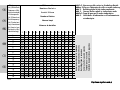
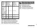
Table 1: Guide numbers at maximum light output (P 1) . . . . . . . . . . . . . 192
Table 2: Flash durations at the individual partial light output levels . . . . 193
Table 3: Camera shutter speeds in stroboscopic mode . . . . . . . . . . . . . 194
Table 4: Recycling times and number of flashes with different battery types . 195
Table 5: Maximum guide numbers at HSS mode . . . . . . . . . . . . . . . . . 195
Table 6: Remote control . . . . . . . . . . . . . . . . . . . . . . . . . . . . . . . . . . . 198
100
http://www.mynikon.com.pl
Foreword
We congratulate you on purchasing this flash unit and thank you for your
confidence in Metz products.
It is only natural that you should want to use your flash unit straight away.
However, we recommend that you study these operating instructions beforehand to be able to fully exploit and utilize all the capabilities offered.
The following operating instructions are conceived such that they describe a
camera + flashgun system combined with the standard foot 301 or an
SCA 3xx2 adapter.
☞ Please also open the back cover page with the illustrations.
This flash unit is compatible with:
• all cameras that have a hot shoe contact
• all cameras that have an accessory shoe without hot-shoe contact, and use
a synch cable (see Optional Extras)
•system cameras
Optimal adaptation to your camera is achieved by using an SCA adapter.
The enclosed SCA 3xx2/3xx Table will indicate the adapter you require for
your particular camera. This table also indicates the special flash functions
that can then be performed.
For more information, visit our web site at www.metz.de
We wish you great pleasure with this new flash unit.
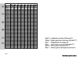
Survey of the operating modes • and special functions ◊:
54 MZ-.. with SCA 3xx2 adapter:
Numerous additional special flash functions are available when the mecablitz 54 MZ-.. is operated with an SCA 3xx2 adapter. It supports virtually
special flash functions offered by prominent camera manufacturers! The
Ǻ all
availability of individual special functions, however, depends on the given
camera system (camera manufacturer) and the specific camera type. For
more detailed information please refer to the SCA Survey Table and the
operating instructions for the individual SCA adapters.
• TTL flash mode1)
- Metz TTL remote mode1)
- Canon ETTL flash mode1)
- Canon ETTL HSS flash mode1) 2)
- Minolta TTL HSS flash mode1) 2)
- Nikon matrix-controlled fill-in flash mode
- Nikon 3D multi-sensor fill-in flash mode
- Nikon D-TTL flash mode3)
- Nikon D-TTL-SD flash mode3)
- Nikon i-TTL-flash mode4)
- Nikon i-TTL-BL-flash mode4)
- Olympus TTL-flash modeflash mode5) with digitalcameras
• Manual flash mode with partial light output levels
• Manual HSS flash mode2) with Canon, Minolta, Nikon
• Automatic flash mode
- Metz auto remote mode
• Stroboscopic mode
◊ Manual flash exposure correction in TTL1) and A mode
◊ Flash bracketing series Fb in TTL and A mode
◊ 1st or 2nd curtain synchronisation
◊ Automatic power-zoom control
◊ Automatic AF measuring beam control
101
http://www.mynikon.com.pl
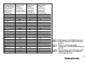
ķ
◊ Automatic maximum flash range indication
◊ Automatic flash synch speed control
◊ Wake-up function
◊ Flash readiness indication in camera’s viewfinder
◊ Correct exposure indication in camera’s viewfinder
◊ Triggering control (Pentax, Minolta)
◊ Anti-red eye preflash (Nikon)
◊ Modelling light function
1) only possible if it can be set on the camera
2) HSS = high speed synchronisation
3) only with 54 MZ-4
4) only with 54 MZ-4i and Nikon SCA-adapter 3402-M3
5) Olympus E-1 only with 54 MZ-4i and SCA-adapter 3202-M3
ķ
54 MZ-.. with SCA 3xx adapter:
The additional special flash functions are restricted when the mecablitz
54 MZ-.. is used with an SCA 3xx adapter! The availability of individual
Ǻ special functions then depends on the given camera system (camera manufacturer) and the special camera type. For more detailed information
please refer to the SCA Survey Table and the operating instructions for
the individual SCA adapters.
• TTL flash mode1)
- Metz TTL remote mode1)
• Manual flash mode with partial light output levels
• Automatic flash mode
- Metz auto remote mode
• Stroboscopic mode
◊ Manual flash exposure correction in A mode
◊ Flash bracketing Fb in A mode
◊ Automatic flash synch speed control
◊ Wake-up function
◊ Flash readiness indication in camera’s viewfinder
◊ Correct exposure indication in camera’s viewfinder
◊ Modelling light function
1) only possible if it can be set on the camera
54 MZ-.. with standard foot 301 (control only via hot shoe or synch cable):
• Manual flash mode with partial light output levels
• Automatic flash mode
- Metz auto remote mode
• Stroboscopic mode
◊ Manual flash exposure correction in A mode
◊ Flash bracketing Fb in A mode
◊ Modelling light function
102
http://www.mynikon.com.pl
1. Safety Instructions
• The flash unit is exclusively intended and approved for photographic
use!
• Never fire a flash in the vicinity of flammable gases or liquids (petrol,
solvents, etc.) - DANGER OF EXPLOSION!
• Never take flash shots of car, bus or train drivers, or of motorcycle and
bicycle riders, whilst they are travelling. They could be blinded by the
light and cause an accident!
• Never fire a flash in the immediate vicinity of the eyes! Flash fired directly in front of the eyes of a person or animal can damage the retina and
lead to severe visual disorders - even blindness!
• Only use the approved power sources listed in the operating instructions!
• Do not expose batteries to excessive heat, sunshine, fire and the like!
• Never throw exhausted batteries on to a fire!
• Exhausted batteries should be immediately removed from the flash unit!
Lye leaking out of spent batteries will damage the unit.
• Never recharge dry-cell batteries!
• Do not expose the flash unit or battery charger to dripping or splashing
water!
• Protect the flash unit from excessive heat and humidity! Do not store the
flash unit in the glove compartment of a car!
• Never place material that is impervious to light in front of, or directly on,
the reflector screen. The reflector screen must be perfectly clean when a
flash is fired. The high energy of the flash light will burn the material or
damage the reflector screen if this is not observed.
• Do not touch the reflector screen after a series of flash shots. Danger of
burns!
• Never disassemble the flashgun! DANGER: HIGH VOLTAGE!
• There are no components inside the flashgun that can be repaired by a
layperson.
• When taking a series of flash shots at full light output and fast recycling
times as provided by NiCad battery operation, make sure to observe an
interval of at least 10 minutes after 15 flashes, otherwise the flash unit
will be overloaded.
ķ
103
http://www.mynikon.com.pl
2. Preparing the flash unit for use
2.2 Power supply
2.1 Mounting the flash unit on the camera
2.2.1 Suitable batteries
☞ Before mounting or removing the flash unit, switch off both the camera and the flash unit!
The mecablitz can only be mounted on the camera with the SCA 301 standard
foot or an SCA 3xx/SCA 3xx2 adapter (optional extra).
As standard, the mecablitz is fitted with the SCA 301 foot for simple flash synchronisation. The shutter speed must be the same or slower than the X synch
speed. The „Set“ version is supplied with the corresponding SCA adapter in
place of the SCA 301 standard foot.
Mounting the standard foot or SCA adapter:
☞ Be sure to switch off the mecablitz by its main switch prior to mounting or removing the standard foot or SCA adapter.
ķ
• Hold the cover plate (only when using the SCA 3xx2 adapter) in the middle
and withdraw.
• Push the SCA adapter or the SCA 301 standard foot all the way in.
Removing the standard foot or SCA adapter:
• Turn off the mecablitz with its main switch (Fig. 1).
• Push the battery compartment lid (Fig. 3) down and fold open.
• Press the coloured unlocking button (Fig. 3) and simultaneously withdraw
the SCA adapter or standard foot.
Mounting the mecablitz:
Insert the mecablitz in the camera’s accessory shoe and lock into position
with the locking screw.
The mecablitz can be operated with any of the following batteries:
• 4 NiCad batteries, type IEC KR 15/51.
They permit fast recycling and are economical in use because they are
rechargeable.
• 4 nickel-metal-hydride batteries.
Significantly higher capacity than NiCad batteries and less harmful to the
environment (no cadmium).
• 4 alkaline-manganese batteries, type IEC LR6.
Maintenance-free power source for moderate power requirements.
• Power Pack P 40 (optional accessory)
Offers microprocessor-controlled battery monitoring and charge level indication (with discharge function).
• Power Pack P 50 (optional accessory)
Offers microprocessor-controlled battery monitoring and charge level indication (with discharge function).
2.2.2 Exchanging batteries
• Switch off the mecablitz with its main switch (Fig. 1).
• Push the battery compartment lid (Fig. 3) down and fold open.
• Insert the batteries in conformity with the indicated battery symbols and
close the battery compartment cover.
☞ CAUTION: When loading batteries ensure correct polarity as indicated
by the symbols on the battery compartment lid .
Exhausted batteries must not be thrown in the dustbin! Help protect
the environment and dispose of exhausted batteries at the appropriate collecting points.
104
http://www.mynikon.com.pl
2.3 Switching the flash unit on and off
The flash unit is switched on with the main switch (Fig. 1). In the upper On
position, the flash unit is permanently6) on and the flash ready (Fig. 1)
indicator is lit.
☞
6) see also „12.3 Automatic shut-off“
When a key appears on the LC display, please refer to „12.2 Locking
and unlocking the controls“.
To turn off the flash unit push the main switch (Fig. 1) down to the bottom
position. If your mecablitz is not going to be used for an extended period of
time, we recommend the following:
- Switch off the flash unit with the main switch (Fig. 1).
- Remove the power source (batteries).
2.4 Operating concept
2.4.1Selecting and setting the flash mode TTL / A / M /
(stroboscopic)
Select the flash mode TTL, A (Auto), M (Manual) or
(stroboscopic) by
depressing the Mode button (Fig. 1) repeatedly until the icon of the required mode flashes on the display. Push the setting disk (Fig. 1) in the direction of the arrow for storage.
The selected operating mode will be automatically stored after approx. 5
seconds if the setting disk (Fig. 1) is not pressed. After storage the icon of
the selected mode will be continuously displayed (without flashing).
Note: The individual flash modes are explained in a separate chapter!
The icon of the given function flashes after the special function has been set,
and the functional status (OFF or On) is shown on the LC display.
The selected function is switched on or off by turning the setting disk (Fig. 1).
The set function is stored by pressing the setting disk (Fig. 1).
Note: The individual flash modes are explained in a separate chapter!
2.4.3 Setting ISO / Zoom / Aperture , „P“ Partial Light Output
and EV (flash exposure correction)
Turn the setting disk (Fig. 1) to select the required function (ISO / Zoom /
Flash Exposure Correction „EV“) on the right-hand side of the LC display. The
selected function is indicated by an arrow ı.
Push the setting disk (Fig. 1) in the direction of the arrow to change the
function. The arrow ı on the LC display will flash. Change the status by turning
the setting disk. To store press the setting disk in the direction of the arrow. The
selected setting will be automatically stored after approx. 5 seconds if the setting disk is not pressed. The arrow at the selected position will stop flashing
after storage.
☞ When operating the mecablitz with an SCA 3xx2 adapter it may not
be possible to change the f–stop (depending on the camera type and
SCA adapter)!
When operating the mecablitz with an SCA 3xx2 adapter it may not
be possible to change the ISO film speed, or the ISO film speed may
not be displayed (depending on the camera type and SCA adapter)!
Note: The individual settings are explained in a separate chapter!
3. TTL flash mode
Additional special functions can be selected in each flash mode with the
Select button (Fig. 1).
By depressing the Select button you can call the special functions "Bleep" ( ),
automatic switch-off
, REAR7) (second-curtain synchronisation), modelling light
, zoom formats and flash bracketing "Fb".
The TTL flash mode is a very simple way to achieve excellent flash shots.
☞ The mecablitz must be fitted with a suitable SCA adapter for TTL flash
mode. TTL flash mode is only possible with cameras supporting this
mode! The SCA 301 standard foot (only hot-shoe contact or synch
cord socket) does not permit TTL flash mode! If the mecablitz is used in
conjunction with a camera or SCA adapter that does not support the
Ȅ
2.4.2 Selecting and setting the special functions
7) only with SCA adapter and camera which support this function
105
http://www.mynikon.com.pl
ķ
TTL function, then uncontrolled full-power flashes will be fired when
the shutter release is pressed! The TTL function can only be tested if a
film has been loaded in the camera!
In TTL mode, the exposure readings are taken by a sensor built into the camera. This sensor measures the light reaching the film through the camera
lens. An electronic control circuit within the camera transmits a stop signal to
the SCA adapter (optional extra) as soon as the film has been exposed by
the correct amount of light, thereby instantly interrupting the flash.
The advantage of this flash mode is that all factors influencing correct exposure of the film (filters, change of aperture and focal length with zoom lenses, extensions for close-ups, etc.) are automatically taken into account.
The „ok“ display on the mecablitz lights up for approx. 3 sec. when flash exposure was correct.
☞ An additional acoustic signal can be activated on the mecablitz; see
„12.1 Bleep function“.
ķ
Setting procedure for the TTL flash mode:
• Equip the mecablitz with a suitable SCA adapter and mount on the camera.
• Adjust the camera as described in its operating manual.
• Switch on the mecablitz with the main switch (Fig. 1).
• Depress the Mode button (Fig. 1) repeatedly until TTL flashes on the
display. Push the setting disk (Fig. 1) in the direction of the arrow to store this setting. The selected operating mode will be automatically stored
after approx. 5 seconds if the setting disk is not pressed. The TTL icon will
stop flashing and will be continuously displayed after storage.
• It is possible that ISO film speed, zoom and f-stop will not be automatically
transmitted from the camera to the mecablitz, depending upon the camera
type and SCA adapter. In this case simply set the corresponding values
manually on the mecablitz. ISO film speed and f-stop are only required for
correct distance and flash range indication on the LC display and are
therefore irrelevant for TTL flash shots. Consequently, it is not imperative to
set them.
• Zoom reflector positioning is important for the correct illumination of the
entire subject. It should therefore always be adapted to the focal length of
the lens.
Tip:
If you are using a zoom lens and do not constantly need the full power and
maximum flash range of the mecablitz, you can leave the zoom reflector at
the shortest focal length of the zoom lens. In this manner the entire subject
will be uniformly illuminated, thereby also eliminating the need to constantly
adapt the zoom reflector position to the given focal length.
Example:
Let us assume that you are using a 28 mm - 80 mm zoom lens. In this case
you set the zoom reflector to position 28 mm!
☞ If the mecablitz is used with an SCA 3xx2 adapter on a camera that
transmits data to the flash unit, it can happen that the ISO speed
rating is not displayed (depending on the camera model); see the
operating instructions for the SCA adapter. It may then be impossible
to change the ISO film speed and aperture! With wide differences in
contrast, e.g. a dark object in the snow, corresponding exposure corrections may be necessary in TTL mode (see Chapter 14.).
3.1 Sub-modes of TTL flash mode
Different flash sub-modes can be set when the mecablitz is in TTL mode.
☞ The number of possible sub-modes depends on the SCA adapter and
the given camera:
• TTL-remote with address „Ad1“
(see Chapter „7.1 Metz cordless TTL remote mode“).
• TTL-remote with address „Ad2”
(see Chapter „7.1 Metz cordless TTL remote mode“).
• E-TTL flash mode (only with SCA 3102 and a suitable Canon camera; see
operating instructions for the SCA adapter and the camera).
• E-TTL-HSS flash mode; high-speed synchronisation (only with SCA 3102
and a suitable Canon camera; see operating instructions for the SCA
106
http://www.mynikon.com.pl
adapter and the camera).
• Matrix-controlled fill-in flash
(only with SCA 3402 and a suitable
Nikon camera; see operating instructions for the SCA adapter and the
camera).
• 3D multi-sensor fill-in flash
(only with SCA 3402 and a suitable
Nikon camera; see operating instructions for the SCA adapter and the
camera).
• TTL-HSS flash mode; high-speed synchronisation
(only with SCA 3302
and a suitable Minolta camera; see operating instructions for the SCA adapter and the camera).
Setting a sub-mode of TTL flash mode:
• Depress the Mode button (Fig. 1) repeatedly until TTL flashes on the
display. In the event that TTL no longer flashes, just press the Mode button
once.
• Turn the setting disk (Fig. 1) and select the required sub-mode.
• Push the setting disk (Fig. 1) in the direction of the arrow for storage.
The selected sub-mode will be automatically stored after 5 seconds if the
setting disk is not pressed. The TTL icon will stop flashing after storage.
4. Automatic flash mode
In the auto flash mode a sensor (Fig. 2) built into the mecablitz measures
the light reflected off the subject. The flash is cut off as soon as sufficient light
has been emitted for correct exposure. This eliminates the need to recalculate
and reset the aperture each time the distance is changed, provided that the
subject remains within the indicated maximum flash range.
The sensor (Fig. 2) of the mecablitz must be directed at the subject,
regardless of the direction in which the main reflector is pointing. The sensor
has a coverage of 25°, and only measures during light emission by the
mecablitz.
The „ok“ display on the mecablitz lights up for approx. 3 sec. when flash
exposure was correct.
The automatic flash mode is possible with an SCA adapter and with the
SCA 301 standard foot.
☞ Some cameras will not support the mecablitz in automatic flash mode
when an SCA adapter is used (see operating instructions for the given
camera and SCA adapter). In this case the mecablitz should be fitted
with the SCA 301 standard foot.
Setting procedure for automatic flash mode:
• Equip the mecablitz with an SCA adapter or the SCA 301 standard foot
and mount on the camera.
• Adjust the camera as described in its operating manual.
• Switch on the mecablitz with the main switch (Fig. 1).
• Depress the Mode button (Fig. 1) repeatedly until A flashes on the
display. Push the setting disk (Fig. 1) in the direction of the arrow for
storage. The selected operating mode will be automatically stored after
approx. 5 seconds if the setting disk is not pressed. The A icon will stop
flashing and remain permanent after storage.
• If the mecablitz is used with an SCA 3xx2 adapter and a camera that automatically transmits the data for ISO film speed, zoom reflector position
and aperture, then no further settings are required. The mecablitz will automatically adjust itself in conformity with the transmitted camera data.
☞ When the mecablitz is operated with a camera that transmits data to
the mecablitz, it can happen that the ISO film speed will not be displayed (depends on the camera type); see operating instructions for
the SCA adapter. It may then be impossible to change the ISO film
speed and aperture setting!
Automatic flash mode with an SCA 3xx adapter or the SCA 301 standard foot:
In this case ISO film speed, zoom reflector position and aperture must be
manually set on the mecablitz. This is indispensable for correct flash exposure because the mecablitz automatically controls the light on the basis of
these data.
107
http://www.mynikon.com.pl
ķ
Tip:
If you are using a zoom lens and do not constantly need the full power and
maximum flash range of the mecablitz, you can leave the zoom reflector at
the shortest focal length position of the zoom lens. In this manner the entire
subject will be uniformly illuminated, thereby eliminating the need to constantly adapt the zoom reflector position to the given focal length.
Example:
Let us assume that you are using a 28 mm – 80 mm zoom lens. In this case
you set the zoom reflector to position 28 mm!
☞ The subject should be located within about 40 % and 70 % of the
distance range indicated on the mecablitz LC display. This gives the
electronic system sufficient leeway for compensation.
Caution with zoom lenses!
Depending on their design, zoom lenses can cause a loss of light in
the order of up to one f-stop. Moreover, the effective aperture may
vary with the focal length settings. This can be compensated by correcting the aperture value on the flashgun manually or by manual
flash exposure correction (see Chapter 14.).
ķ 4.1 Sub-modes of the automatic flash mode
Different sub-modes can be set when the mecablitz is in auto flash mode A:
• Auto-remote with address „Ad1“
(see Chapter „7.1 Metz cordless auto remote mode“)
• Auto-remote with address „Ad2“
(see Chapter „7.1 Metz cordless auto remote mode“)
Setting a sub-mode of the automatic flash mode:
• Depress the Mode button (Fig. 1) repeatedly until A flashes on the
display.
• Turn the setting disk (Fig. 1) to set the desired sub-mode.
• Push the setting disk (Fig. 1) in the direction of the arrow for storage.
The selected sub-mode will be automatically stored after approx. 5 seconds if
the setting disk is not pressed. After storage, icon A will stop flashing.
5. Manual flash mode
In this mode, the flash unit will emit the full light energy if partial light output
has not been set. The mecablitz must be fitted with an SCA adapter or the
301 standard foot. Adaptation to the given photographic situations is by setting the corresponding aperture on the camera and by selecting a partial
light output level.
The LC display of the mecablitz indicates the flash-to-subject distance for correct flash exposure. It is therefore necessary to ensure that the mecablitz is
correctly adjusted. The aperture and ISO film speed set on the camera must
be identical to the aperture and ISO film speed setting on the mecablitz! The
flash reflector’s zoom position must be adapted to the focal length of the lens!
Setting procedure for manual flash mode:
Setting example:
Flash-to-subject distance: 6 m; zoom 50 mm; film speed ISO 100/21°.
• Adjust the camera as indicated in the operating instructions.
• Equip the flash unit with the SCA 301 standard foot or the SCA adapter
and mount on the camera.
• Switch on the mecablitz with the main switch (Fig. 1).
• Depress the Mode button (Fig. 1) repeatedly until M flashes on the
display. Push the setting disk (Fig. 1) in the direction of the arrow for storage. The selected operating mode will be automatically stored after approx.
5 seconds if the setting disk is not pressed. After storage the M icon will stop
flashing and remain permanent.
• The display indicates the light output „P 1/1“ (= full light output) after storage. A full-power flash is fired when pressing the firing button (Fig. 1)
on the mecablitz or the camera’s shutter release.
☞ Some cameras will not support the mecablitz with an SCA adapter
when it is in manual mode (see operating instructions for the given
camera and SCA adapter). In this event the mecablitz should be
equipped with the SCA 301 standard foot (see also operating instructions for the given camera).
108
http://www.mynikon.com.pl
Manual flash mode of the mecablitz with an SCA 3xx2 adapter:
If the mecablitz is operated with an SCA 3xx2 adapter and a camera that
automatically transmits the parameters for ISO film speed, zoom reflector
position and aperture, then no further settings are required. The mecablitz
will automatically adjust itself in conformity with the data transmitted by the
camera.
☞ If the mecablitz is used on a camera that transmits data to the mecablitz,
it can happen that the ISO film speed will not be displayed (depends on
the camera type); see the operating instructions for the SCA adapter. If
the mecablitz is being operated with a camera that transmits data to the
flash unit, it is impossible to change the values for ISO film speed and
aperture! In this event continue changing the f-number on the camera
until the required distance is indicated on the LC display of the mecablitz.
Manual flash mode with the SCA 3xx adapter or the SCA 301 standard foot:
In this case the corresponding ISO film speed, zoom reflector position and
aperture parameters must be manually set on the mecablitz. This is indispensable for correct flash exposure because the mecablitz calculates and displays the flash-to-subject distance required for a correct exposure on the basis of these data.
Setting partial light output:
Partial light output can be set on the mecablitz if you wish to change the distance range given for correct flash exposure in order to adapt it to the existing picture-shooting situation:
• Continue turning the setting disk (Fig. 1) until the arrow symbol appears
next to P on the display.
• Push the setting disk (Fig. 1) in the direction of the arrow. The arrow
symbol starts flashing.
• Turn the setting disk to set the required partial light output level. Press the
setting disk in the direction of the arrow for storage. The selected partial
light output will be automatically stored after approx. 5 seconds if the setting disk is not pressed. After storage the arrow symbol stops flashing.
Another possibility to modify the distance range for adaptation to the individual picture shooting situation is to change the aperture on the camera. You
must, however, take into account that a change of the camera’s aperture also
influences the picture’s depth-of-field.
Deleting the set partial light output:
• Turn the setting disk (Fig. 1) until the arrow symbol appears next to P on
the display.
• Push the setting disk (Fig. 1) in the direction of the arrow. The arrow
symbol starts flashing.
• Turn the setting disk (Fig. 1) to select partial light output P 1/1. Push the
setting disk in the direction of the arrow for storage. Storage is automatic
after 5 seconds if the setting disk is not pressed. The arrow symbol will stop
flashing after storage. The partial light output is set to P 1/1 when changing to another flash mode.
5.1 Sub-mode of the manual flash mode
☞ The mecablitz must be fitted with an SCA 3xx2 adapter!
Various cameras offer the possibility of high-speed synchronisation (FP and
HSS flash mode) when the mecablitz is in manual flash mode M (see operating instructions of the given camera and SCA adapter).
Setting the „M-HSS“ sub-mode of the manual flash mode:
• Continue depressing the Mode button (Fig. 1) until M flashes on the
display.
• Turn the setting disk (Fig. 1) to set HSS.
• Push the setting disk in the direction of the arrow for storage. HSS will be
automatically stored after approx. 5 seconds if the setting disk is not pressed.
The M icon will stop flashing after storage.
Deactivating the “HSS” mode:
• Press the Mode button (Fig. 1) repeatedly until M flashes on the display.
• Turn the setting disk (Fig. 1) to cancel HSS.
• Press the setting disk in the direction of the arrow for storage. Storage will
109
http://www.mynikon.com.pl
ķ
be automatic after 5 seconds if the setting disk is not pressed. The M icon
will stop flashing after storage.
6. Bounce flash
ķ
Photos shot with full frontal flash are easily recognized by their harsh, dense
shadows. This is often associated with a sharp drop in light from the foreground to the background.
This phenomenon can be avoided with bounce flash because the diffused
light will produce a soft and uniform rendition of both the subject and the
background. For this situation the reflector is turned in such a manner that
the flash is bounced off a suitable reflective surface (e.g. ceiling or walls of
the room).
The reflector can be turned vertically and horizontally.
Vertikal positions:
-7°, 0°, 60°, 75°, 90°
Horizontal positions: -180°, -150°, -120°, -90°, -60°, -30°, 0°, 30°, 60°, 90°.
The reflector head is mechanically interlocked in its basic position. Press the
pushbutton to unlock and turn the reflector head.
☞ When turning the reflector vertically or horizontally, it is essential to
ensure that it is moved by a sufficiently wide angle so that direct light
can no longer fall on the subject. Consequently, always turn the reflector at least to the 60° lock-in position. The distance readings on the LC
display will disappear. The flash-to-subject distance via the ceiling or
wall is an unknown magnitude.
The light bounced off the reflecting surfaces produces a soft and uniform illumination of the subject.
The reflecting surface must be white or have a neutral colour, and it must not
be structured, e.g. wooden beams in a ceiling, as these might cast shadows.
For colour effects just select the reflective surface in the desired colour.
Use the secondary reflector to avoid disturbing dense shadows that are
formed by bounce flash, for instance under the nose and in the eye sockets
for portraiture.
6.1 Bounce flash with secondary reflector
The secondary reflector (Fig. 1) produces frontal fill-in light when the flash
is bounced.
☞ Use of the secondary reflector is only meaningful in bounce flash
photography.
The secondary reflector is switched on and off with switch
(Fig. 2). A
flashing
symbol on the LC display of the mecablitz merely indicates that
the main reflector has not yet been turned.
Activation of the secondary reflector assigns approx. 85 % of the emitted
light to the main reflector and 15 % to the secondary reflector. These %-values can differ somewhat when shooting with partial light output and secondary reflector.
The light output of the secondary reflector can be reduced by approx. 50 %
with a light reducing filter if it is too bright. For this purpose shift the light reducing filter sideways, remove from the mecablitz, turn by 180°, place over the
secondary reflector and push down until it audibly clicks into position.
☞ The sub-modes ADI, stroboscope, E-TTL, E-TTL-HSS, D-TTL, 3D multi-sensor
and TTL-HSS are not possible in conjunction with the secondary reflector.
6.2 Bounce flash in automatic and TTL flash mode
Prior to picture taking it is advisable to check whether sufficient light is available for the selected aperture. For this purpose proceed in the manner described in Chapter „10. Correct exposure indication“.
6.3 Bounce flash in manual flash mode
The required aperture on the camera in the manual flash mode is best established with a flash meter. If a flash meter is not available, observe the following rule of thumb
guide number
Camera aperture = —————————————————
flash-to-subject distance x 2
to establish a guide value for the aperture that can then be varied by ±1 f-stop
for the shot to be taken.
110
http://www.mynikon.com.pl
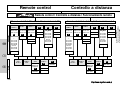
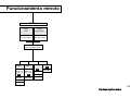
7. Remote mode
General
In the remote mode, additional flash units (slaves) are fired under the cordless control of the master flash unit (controller) mounted on the camera. The
controller extends TTL automatic exposure control to all slaves.
The Metz TTL remote mode enables joint cordless TTL flash control of several
flash units of the types 54 MZ-.., 34 CS-2, 28 CS-2, 40 MZ-.., 50 MZ-5 and
70 MZ-... For this mode all additional 54 MZ-.. and 70 MZ-4 flash units (slaves) must be fitted with an SCA 3083 slave adapter (optional extra), and all
40 MZ-.. slaves with the SCA 3080 or 3082 slave adapter. The slave flash
units can be mounted on the foot supplied with the slave adapter or on a tripod.
The slave flash units 34 CS-2, 28 CS-2, 50 MZ-5 Slave and 70 MZ-5 do not
require a slave adapter.
☞ The LC display of the mecablitz does not indicate the maximum flash
range when in remote mode. The secondary reflector of the mecablitz
must be switched off!
To ensure that two TTL remote systems in neighbouring rooms do not interfere
with each other, two different addresses - Ad1 and Ad 2 - can be selected on
the controller (master) and the slave unit.
7.1 Metz cordless TTL remote mode
☞ The Metz TTL remote mode is only possible with cameras featuring TTL
flash control!
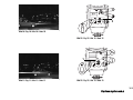
Setting procedure for Metz TTL remote controller operation (Fig. 4):
1 Equip the flash unit mounted on the camera with the appropriate SCA adapter and turn on with the main switch.
2 Depress the Mode button (Fig. 1) repeatedly until TTL flashes on the
display.
3 While the TTL mode is flashing, turn the setting disk (Fig. 1) and select
the address Ad1 or Ad2 for the Co controller mode. Depress the Mode but-
ton in the event that TTL is no longer flashing. Briefly press the setting disk
in the direction of arrow for storage. The selected setting will be automatically stored after 5 seconds if the setting disk is not pressed. TTL will then
be permanently displayed (without flashing), together with Co and the slave address Ad1 or Ad2.
Setting procedure for Metz TTL remote slave operation (Fig. 5):
• Equip the 54 MZ-.., 70 MZ-4 slave flash units with an SCA 3083 slave
adapter, and the 40 MZ-.. slave flash unit with an SCA 3080 or 3082 slave adapter.
1 Switch on the mecablitz with the main switch (Fig. 1). The mecablitz is
automatically set to TTL mode, and SL (slave mode) is indicated on the
LC display. The adjusted slave address is Ad1 (or the last selected address).
2 If you wish to change the slave address, press the Mode button (Fig. 1).
The TTL mode icon will then flash.
3 Turn the setting disk (Fig. 1) and select Ad2. Push the setting disk in the
direction of the arrow for storage.
☞ When in remote mode, the power zoom reflector of the mecablitz is
automatically adjusted to the 24 mm position in order to achieve the
widest possible illumination. This reflector position can be manually
changed (see Chapter 12.).
• When flash readiness is reached, the flash-ready indicator of the slave
lights up and the AF measuring beam starts flashing. An additional acousstic signal (bleep) can be activated to indicate flash readiness (see Chapter 12.). This is useful when there is no visual contact with the AF measuring beam or the flash-ready indicator.
4 Press the manual firing button (Fig. 1) of the mecablitz controller
mounted on the camera to fire a test flash.
• The slave will respond with a delayed flash to indicate that it is ready for
operation. When several slave units are operated, then all slaves will
acknowledge flash readiness simultaneously.
If a slave does not respond by firing a delayed flash, then this means that
the sensor in the adapter did not receive the light pulse. Turn the sensor in
111
http://www.mynikon.com.pl
ķ
the direction of the controller and repeat the procedure described in step 4.
☞ A particularly short distance between controller and slave unit may
cause the camera’s electronic system to cut off the flash before the
slave has received its light pulse. In such an event widen the distance
between the controller and slave or select a higher f-number and
repeat procedure No. 4.
Deactivating the Metz TTL remote mode:
• Press the Mode button (Fig. 1) on the controller and deactivate the controller mode with the setting disk (Fig. 1).
• On the slave:
Switch off the flash unit, remove the SCA 3083 slave adapter, and finally
switch on the flash unit again.
7.2 Metz cordless auto remote mode
☞ The Metz auto remote mode can be used with system, standard, old
mechanical and medium-format cameras. The only precondition is
that all cameras feature a synch contact/socket and that the flash unit
is equipped with an SCA 301 standard foot or SCA adapter.
The exposure is controlled by the sensor of the controller flash unit
(master) mounted on the camera.
ķ
Setting procedure for the Metz auto remote controller mode:
• Equip the mecablitz with an SCA adapter or the SCA 301 standard foot,
and switch on.
• Switch the camera to manual mode as described in the camera’s operating
instructions.
☞ Automatic flash mode or auto remote flash mode are not supported
by all cameras in conjunction with an SCA adapter (see operating
instructions of the camera and the SCA adapter). If a camera, in combination with an SCA adapter, does not support the automatic flash
mode, then equip the mecablitz with the SCA 301 standard foot. In
this event do not forget to manually transfer the camera settings (ISO,
f-stop and zoom position) to the mecablitz!
• Set a shutter speed of 1/60th sec. or slower.
• Switch on the mecablitz on the camera with the main switch (Fig. 1).
• Depress the Mode button (Fig. 1) repeatedly until A appears on the
display.
• While the A mode is flashing, turn the setting disk (Fig. 1) and select the
address Ad1 or Ad2 for the Co controller mode. Depress the Mode button
in the event that A no longer flashes. To store, briefly press the setting disk
in the direction of the arrow. The selected setting will be automatically stored after 5 seconds if the setting disk is not pressed. A will then be continuously displayed (without flashing), together with Co and the slave address
Ad1 or Ad2.
Setting procedure for Metz auto remote slave mode:
The setting procedure is the same as for Metz TTL remote slave mode.
The slave flash unit also operates in the TTL mode in the auto remote mode.
7.3 Assessing the overall lighting conditions in remote mode
A modelling light beam of all participating flash units can be fired to assess
the overall lighting conditions in A (auto) and TTL remote mode.
For this purpose, the firing button (Fig. 1) of the 54 MZ-.. mounted on
the camera must be programmed. Press the Select button (Fig. 1) repeatedly until the mode display
lights up. Turn the setting disk (Fig. 1) to
set the modelling light function to On or OFF. The modelling light can then be
fired with the firing button (Fig. 1) ; see also Chapter 12.
8. Fill-in flash in daylight
The mecablitz can also be used for fill-in flash in daylight to soften harsh shadows and diminish the contrast, thereby producing a more balanced exposure when shooting against the light (contre-jour). Various possibilities are
open to the user for fill-in flash.
112
http://www.mynikon.com.pl
8.1 Fill-in flash in TTL mode
The mecablitz must be equipped with a suitable SCA adapter. The camera
must be able to support TTL fill-in flash.
• Press the Mode button (Fig. 1) repeatedly until TTL appears on the
display.
Most cameras automatically activate fill-in flash when in Full Auto Mode, Intelligent Program AE P, and in Programmmed Image Control Modes during
daylight (see also operating instructions of camera and SCA adapter). The
camera will then automatically ensure a well-balanced illumination of subject
and background.
Moreover, some cameras offer a special fill-in flash program which permits
pin-pointed use whenever required. Depending upon the camera type, activation is either on the camera or mecablitz (see operating instructions of camera and SCA adapter).
Example: Matrix-controlled fill-in flash (only for certain Nikon cameras)
The mecablitz must be equipped with the SCA 3402 adapter (Nikon)!
Various Nikon cameras support the „Matrix-controlled TTL fill-in flash mode“
(see operating instructions of the given camera and the SCA adapter). This flash
mode is a sub-mode of TTL flash mode. Chapter 3.1 describes how it is set.
Example: 3D multi-sensor fill-in flash (only for certain Nikon cameras)
The mecablitz must be equipped with the SCA 3402 adapter (Nikon)!
Various Nikon cameras support the „3D multi-sensor fill-in flash mode“ (see
operating instructions of the given camera and the SCA adapter). This flash
mode is a sub-mode of TTL flash mode. Chapter 3.1 describes how it is set.
8.2 Fill-in flash in automatic mode
• Switch on the mecablitz with the main switch (Fig. 1).
• Depress the Mode button (Fig. 1) repeatedly until A flashes on the
display. Push the setting disk (Fig. 1) in the direction of the arrow to store this setting. The selected operating mode will be automatically stored
after approx. 5 seconds if the setting disk is not pressed. The A symbol will
remain permanent and stop flashing after storage.
☞ In automatic mode the flash is controlled by the sensor built into the
mecablitz. Ensure that backlight does not shine directly on to the sensor as this will confuse the electronics of the flash unit.
Use the camera’s or a hand-held exposure meter, to establish the required
aperture and shutter speed for a normal exposure. Ensure that the shutter
speed either equals, or is slower than the fastest flash synch speed (varies
with different camera models).
Example:
Established aperture = f/8;
Established shutter speed = 1/60th sec.
Flash synch speed of the camera e.g. 1/100th sec.
(see operating instructions for the given camera).
The two established values for aperture and shutter speed can be set on the
camera because the camera’s shutter speed is slower than the camera’s flash
sync speed.
To obtain a balanced fill-in light, for instance in order to retain the character
of the shadows, it is advisable to select on the flashgun an auto aperture that
is one increment lower than the aperture set on the camera. In our example
f/8 was set on the camera. Consequently, we advise you to set f/5.6 on the
flash unit.
If the mecablitz is fitted with an SCA 3xx2 adapter and the camera automatically transmits the f-stop values to the mecablitz, then manual aperture setting
is no longer possible! In this case manual flash-exposure correction can be
used in the automatic flash mode (see Chapter 14.).
Manual flash-exposure correction in automatic mode can also be used if the
camera does not transmit any data to the mecablitz.
Additional correction of the aperture value is then no longer necessary!
Tip:
If possible, take a meter reading of the subject’s background separately from the
actual subject. Experience has shown that a correction value of -1 EV (f-stop) to
113
http://www.mynikon.com.pl
ķ
1 2/3 EV for the auto aperture on the mecablitz produces the best results in fillin flash mode.
9. Stroboscopic mode (Fig. 6)
ķ
Stroboscopic flash mode makes several images of a moving object appear in
the same picture. This is particularly interesting for motion studies and for
special effects (Fig. 6). In stroboscopic mode, a predetermined number of
flashes are fired at a certain flash frequency. Consequently, only a partial
light output is available, with a maximum of 1/4 power.
For stroboscopic exposures you can select a flash frequency (flashes per second) of 1...50 Hz in 1 Hz increments, and a number of flashes between
2...50 in single increments.
No ISO film speed is displayed in stroboscopic mode. When using the mecablitz with an SCA 3xx2 adapter and a camera that automatically transmits
the speed rating to the flash unit, the mecablitz will automatically adjust the
film speed (see operating instructions for camera and the SCA adapter).
When using the mecablitz with an SCA 3xx adapter, the SCA 301 standard
foot or a camera that does not transmit film speed data, the speed of the loaded
film must be set in TTL, A or M mode before selecting stroboscopic mode. The
mecablitz will then take over this setting for the stroboscopic mode.
The maximum possible partial light output level in stroboscopic mode is automatically adjusted. To achieve short flash durations, the partial light output
level can be adjusted manually to a minimal value of 1/256. The LC display
indicates the shooting distance for correct exposure at the set parameters.
You can adjust the displayed distance to the actual shooting distance by varying the f-stop or the partial light output level. The aperture selected on the
flash unit must be set on the camera lens. By using faster films (higher ISO
number) the shooting distance can be increased.
☞ The stroboscopic mode cannot be used when the secondary reflector
is switched on.
Setting procedure for stroboscopic mode (Fig. 7):
• Adjust the camera to manual mode, as explained in the manufacturer’s
operating instructions, and select the corresponding shutter speed.
1 Equip the flash unit with an SCA adapter or the SCA 301 standard foot,
and switch on with the main switch (Fig. 1).
2 Depress the Mode button (Fig. 1) repeatedly until
flashes on the
display. Press the setting disk (Fig. 1) in the direction of the arrow to store
this setting. The selected operating mode will be automatically stored after
approx. 5 seconds if the setting disk is not pressed. The
icon will stop
flashing after storage.
Stroboscopic mode when the mecablitz is fitted with an SCA 3xx2 adapter:
If the mecablitz is operated with an SCA 3xx2 adapter and a camera that
automatically transmits the ISO film speed, zoom reflector position and aperture parameters, then no further settings will be necessary. The mecablitz will
automatically adjust itself according to the data transmitted by the camera.
The number of flashes and the flash frequency must be set as explained in
Sections 3 and 4 (see below).
☞ If the mecablitz is operated with a camera that transmits data to the
mecablitz, then the ISO film speed and the aperture cannot be changed.
Stroboscopic mode with an SCA 3xx adapter, the SCA 301 standard foot
or a camera that does not transmit data (Fig. 7):
In this case the corresponding values for ISO film speed, zoom position of the
reflector and the aperture must be manually adjusted on the mecablitz. This
is indispensable for correct flash exposure because the mecablitz uses these
data to calculate and display the flash-to-subject distance required for correct
flash exposure.
3 Determine the N number of flashes. To do so, turn the setting disk (Fig.
1) until the arrow is in top position. Depress the setting disk and turn to
adjust the required N number of flashes. Store this setting by renewed
depression of the setting disk.
114
http://www.mynikon.com.pl
4 Select the flash frequency f(Hz). Turn the setting disk (Fig. 1) anti-clokkwise until the arrow is next to f(Hz). Depress the setting disk and turn to
select the required flash frequency f(Hz). Store this setting by renewed
depression of the setting disk.
☞ The distance to the moving subject is used as distance value. To prevent overexposure of the static this part of the picture should either be
very dark or far behind the moving subject. Best results are achieved
with a low ambient light level.
then readjusted to TTL mode.
This procedure is relatively accurate with lenses of medium focal length of
between 28 mm and 85 mm. However, in borderline cases, underexposure
may result in TTL mode. In such an event the o.k. exposure indicator will remain dark after the shutter has been released. Select the next larger aperture
(e.g. f/8 instead of f/11) and have another try.
Ensure that a sufficiently slow shutter speed is set on the camera.
Table 3 specifies the fastest camera shutter speeds for the N - f(Hz) combinations.
☞ The AF measuring beam
10. Correct exposure indication
The correct exposure indicator ”o.k.” (Fig. 1) only lights up if the picture
was correctly exposed in automatic or TTL flash mode.
This gives the user the opportunity to fire a test flash while in automatic flash
mode so that the correct aperture can be established beforehand. This is particularly valuable with bounce flash when reflection conditions are difficult to
judge. A test flash cannot be fired in TTL mode.
The test flash can be triggered with the manual firing button (Fig. 1) provided that this button has not been programmed for „Modelling Light“ (see
Chapter 12.).
If the o.k. exposure indicator (Fig. 1) remains dark after the test flash was
fired, then adjust the next lower f-number, or diminish the distance to the
reflecting surface or subject, and repeat the test flash.
The f-stop established in this manner must also be set on the camera.
☞ To trigger a test flash, hold the camera and flash unit in the same
manner as for the actual shot!
11. AF measuring beam
(Fig. 2) can only be activated by autofocus
cameras that support the AF measuring beam of the flash unit! Some
autofocus cameras only support their own built-in AF illuminator (refer
to the operating instructions for the given camera). The mecablitz must
be fitted with an SCA 3xx2 adapter!
Please note when selecting the camera’s autofocus mode that most cameras
only support the AF measuring beam in the „Single AF“ or „One-Shot AF“
mode (see operating instructions for the camera)!
The AF measuring beam is activated by the camera electronics when the ambient lighting conditions are insufficient for automatic focusing. The AF beam
projects a striped pattern on to the subject, and the camera uses this pattern to
focus automatically. The AF beam has a range of 9 m (with a 50 mm f/1.7
standard lens). Low-speed zoom lenses can significantly curtail the range of
the AF measuring beam.
☞ Some autofocus cameras have several AF metering fields in addition
to the central AF metering area in the camera’s viewfinder. The striped
pattern of the AF measuring beam only supports the camera’s central
AF sensor. Consequently it may be necessary to adjust the central AF
sensor manually on the camera (see the operating instructions for the
given camera and the SCA adapter).
This facility can also be used with TTL mode without having to produce test
exposures. The flash unit is adjusted to automatic mode, and the correct
aperture is then determined with a test flash in the previously described manner. The established aperture is transferred to the camera and the flash unit is
115
http://www.mynikon.com.pl
ķ
12. Special functions
The special functions of the mecablitz can be called, one after the other, by
depressing the Select button (Fig. 1), and they can be set, switched off
and stored with the setting disk (Fig. 1).
12.1 Bleep function
ķ
(acoustic alarm)
The bleep function is used to acoustically indicate certain mecablitz functions. It enables the photographer to concentrate fully on the subject without
being distracted by the need to observe additional visual status displays!
The bleep function acoustically indicates the following:
• Flash readiness
• Correct flash exposure
• Automatic shut-off of the flash
• Incorrect operation
Acoustic signal after the mecablitz has been switched on:
• A brief (approx. 2 sec.) uninterrupted bleep signal after the mecablitz has
been switched on indicates flash readiness.
Bleep signals after exposure:
• A brief (approx. 2 sec.) uninterrupted bleep signal immediately after shooting indicates that exposure was correct and that flash readiness continues.
If there is no bleep signal immediately after shooting the picture was underexposed.
• An intermittent bleep signal immediately after shooting confirms correct
flash exposure, but flash readiness will only be re-established after a subsequent (3 sec.) continuous bleep.
Bleep signals associated with settings in „A“ automatic mode:
• A short bleep as an acoustic alarm is generated in the auto flash mode of
the mecablitz if the selected aperture and ISO setting exceed the permissible light control range. The auto aperture of the mecablitz is then automatically adjusted to the next permissible value.
Setting the bleep function (Fig. 9):
1 Press the Select button (Fig. 1) repeatedly until the icon flashes.
2 Turn the setting disk (Fig. 1) and switch on the bleep function. „On“
appears on the LC display of the mecablitz. This setting will be stored when
the setting disk is briefly pushed in the direction of the arrow. The selected
setting will be automatically stored after 5 seconds if the setting disk is not
pushed.
Deactivating the bleep function (Fig. 9):
1 Press the Select button (Fig. 1) repeatedly until the icon flashes.
2 Turn the setting disk (Fig. 1) and switch off the bleep function. „OFF“
will then appear on the LC display of the mecablitz. Push the setting disk
briefly in the direction of the arrow to store this setting. The selected setting
is automatically stored after 5 seconds if the setting disk is not pushed.
12.2 Locking and unlocking the controls (key function)
The key function locks the Mode and Select buttons, as well as the setting
disk, from inadvertent resetting.
To lock the Mode and Select buttons press them simultaneously for approx. 3 seconds until the
key icon appears on the display.
To unlock the Mode and Select buttons press them simultaneously for approx.
3 seconds until the
key icon disappears from the display.
12.3 Automatic shut-off (Afb. 8)
To protect the batteries from unintentional discharge, the mecablitz can be set
to automatically switch off 1 minute or 10 minutes after the flash was activated for the last time (flash shot, setting procedure or tripping the camera’s
shutter release).
The last used mode is retained after automatic shut-off so that it becomes
instantly available when the flash unit is switched on again.
If the mecablitz is equipped with the SCA 3xx2 adapter, it can be switched
on again merely by touching the camera’s shutter release.
If the mecablitz is equipped with an SCA 3xx adapter or the SCA 301 stand-
116
http://www.mynikon.com.pl
Ȅ
ard foot, it can be switched on again merely by actuating the setting disk.
Setting automatic shut-off (Fig.8):
1 Press the Select button (Fig. 1) of the mecablitz repeatedly until the clock
icon
flashes.
2 Turn the setting disk (Fig. 1) to select the „Auto shut-off time“ 1m
(1 minute) or 10m (10 minutes). “On” is additionally displayed. Briefly press
the setting disk in the direction of the arrow for storage. The selected setting
will be automatically stored after 5 seconds if the setting disk is not pressed.
The clock icon
will then appear on the LC-display of the mecablitz.
☞ Switch off the mecablitz by its mains switch if it is not going to be
used for an extended period of time!
Ȅ
Ȅ
Deactivating automatic shut-off:
1 Repeatedly depress the Select button (Fig. 1) until the clock symbol
flashes. Turn the setting disk until “OFF” is displayed. Press the setting disk
briefly in the direction of the arrow to store this setting.
2 The selected setting is automatically stored if the setting disk is not pressed
within 5 seconds. The clock symbol
on the LC display of the mecablitz
is deleted.
Ȅ
12.4 REAR – Second curtain synchronisation (Fig. 10 and 11)
Second curtain synchronization (REAR) is particularly advantageous when
using slow shutter speeds (slower than 1/30 s) or when shooting moving
objects that have their own source of light. Second curtain synchronisation
gives a more realistic impression of movement because the light streaks behind the light source instead of building up in front of the source, as is the
case when the flash is synchronised with the 1st shutter curtain.
☞ The REAR function can only be used if the mecablitz is fitted with an
appropriate SCA adapter and is mounted on a camera that supports
this function. The camera must be switched on to select and set this
function. The camera’s shutter release must be briefly touched at least
once so that the corresponding data can be exchanged between the
camera and the mecablitz and the attached SCA adapter.
Please refer to the respective operating instructions to find out whether or not
the camera and the SCA adapter support the REAR function.
On some cameras the REAR function is not possible in certain operating
modes so that it cannot be selected. It will then be automatically deleted.
Please refer to the respective operating instructions for the given camera and
the SCA adapter!
Switching on the REAR function:
• Press the Select button (Fig. 1) repeatedly until „REAR“ appears on the
LC display. Adjust „On“ with the setting disk. Push the setting disk in the
direction of the arrow to store the REAR function. The selected setting will
be automatically stored after 5 seconds if the setting disk is not pushed.
After the REAR function has been set, the „REAR“ symbol for second curtain
synchronisation will be indicated on the LC display of the mecablitz.
Tip:
Mount the camera on a tripod for this mode to avoid camera shake with slow
shutter speeds.
☞ Turn off this function after shooting, otherwise unwanted slow shutter
speed could result in camera shake with „normal“ flash shots in the P
camera mode or in the programmed image control modes of the camera.
The „REAR“ function can be directly set on some cameras. In this case, however, the mecablitz will not display „REAR“.
Deactivating the REAR function:
• Repeatedly press the Select button (Fig. 1) until „REAR“ appears on the
LC display. Adjust „OFF“ with the setting disk. Press the setting disk in
direction of the arrow for storage. The setting will be automatically stored
after 5 seconds if the setting disk is not pressed. The REAR symbol on the
LC display of the mecablitz is deleted.
117
http://www.mynikon.com.pl
ķ
ķ
12.5 Modelling light ML
12.6 Adapting the focal length to the camera format
The modelling light is a sequence of stroboscopic flashes at high frequency
during approx. 4 seconds which give the impression of permanent light.
Modelling light enables the user to assess light distribution and shadow formation before taking pictures.
Setting the modelling light function:
• Repeatedly depress the Select button (Fig. 1) until the
icon flashes on
the LC display. Select „On“ with the setting disk. Push the setting disk in
direction of the arrow to store the function. The modelling light function will
be automatically stored after 5 seconds if the setting disk is not pressed.
If an SCA 3xx2 adapter is used, the flash ready indicator (Fig. 1) flashes on the mecablitz to indicate that the modelling light function has been
activated. The modelling light is triggered by the mecablitz when the button is pressed.
In Metz REMOTE mode (TTL and Auto REMOTE), triggering the controller’s
modelling light will cause the modelling light on all slaves to be fired simultaneously (with 40 MZ-... in combination with the SCA 3080 adapter as from
version M1 or an SCA 3082 adapter).
A fully charged set of batteries (600 mAh) is sufficient to trigger the modelling
light approx. 60 times. Dry-cell batteries are not recommendable for the modelling light mode because their higher internal resistance impedes the fast
supply of power required by the flash capacitor.
Deactivating the modelling light function:
• Depress the Select button (Fig. 1) repeatedly until the
icon flashes on
the LC display. Select „OFF“ with the setting disk. Press the setting disk (Fig. 1) in direction of the arrow for storage. The setting will be automatically
stored after 5 seconds if the setting disk is not pressed.
The flash ready indicator (Fig. 1) lights permanently on the mecablitz.
This function enables the user to adapt the indicated zoom reflector position
of the mecablitz to the camera format. Consequently, the focal length of lenses of medium-format cameras (4.5x6, 6x6, 6x7 and 6x9) or APS cameras
can be matched to the value displayed on the mecablitz. For 35 mm (24x36)
cameras, the Extended-Zoom function is additionally available.
The Extended-Zoom mode reduces the focal length of the mecablitz by one increment as compared to the focal length of the camera lens. This results in a
wider illumination and additional diffused light (reflections) in rooms, which, in
turn, produces a softer flash illumination.
Example of Extended-Zoom mode:
The focal length of the camera lens is 50 mm.
In the Extended-Zoom mode the mecablitz adjusts the reflector position to 35 mm.
Setting procedure to adapt the focal length to the camera format (Fig. 12):
1 Depress the Select button repeatedly until „Zoom“ appears on the display.
2 Turn the setting disk (Fig. 1) to adapt the focal length to the given camera
format:
Key to the displays:
Zoom without additional display = Setting for 35 mm format (= normal setting).
Auto Zoom with the following additional displays:
E
Extended-Zoom mode (only for 35 mm cameras) (Fig. 12)
APS
Adaptation to APS cameras
F1
Adaptation to medium format cameras: 4.5x6
F2
Adaptation to medium format cameras: 6x6, 6x7 or 6x9
Informs that the Extended Zoom mode has been activated.
• Having selected the required setting, press the setting disk (Fig. 1) in the
direction of the arrow for storage. The selected setting is automatically stored
after 5 seconds if the setting disk is not pressed. The setting is retained after
the mecablitz has been switched off.
The
symbol that appears on the LC display of the flash unit after storage
118
http://www.mynikon.com.pl
indicates that one of the afore-listed focal length adaptations is set.
12.7 Flash bracketing “Fb” (Fig. 13)
A series of flash exposures known as flash bracketing / flash exposure
bracketing can be made with the mecablitz 54 MZ-.. in the TTL and A modes.
A flash bracketing series consists of three successive flash shots with different
flash exposure correction values. The first shot in the series is taken without a
correction value, the second one with a minus correction, and the third one
with a plus correction. The mode is automatically cancelled after the third
shot.
„Fb“ flash bracketing in TTL mode:
Flash bracketing in TTL mode is only possible if the mecablitz is fitted with a
suitable SCA adapter (SCA 3xx2) and if the camera supports manual flash
exposure with the mecablitz.
If the camera does not support manual flash exposure, a correction factor for
flash bracketing can be set on the mecablitz, but the camera will expose the
pictures without such correction. Please refer to the operating instructions for
the given camera and the SCA adapter!
„Fb“ flash bracketing in A mode:
For flash bracketing in A mode, it is sufficient if the mecablitz is equipped
with an SCA 301 standard foot. However, flash bracketing in A mode is also
possible with an SCA adapter!
☞ With some cameras ”Fb” flash bracketing in A mode is not possible
for technical reasons!
With some cameras flash bracketing in the automatic mode is not possible if
the mecablitz is not equipped with an SCA 301 standard foot.
Please refer to the operating instructions for the given camera and SCA
adapter.
Activating “Fb” flash bracketing (Fig. 13):
1 Repeatedly depress the Select button (Fig. 1) until „Fb“ appears on the
display.
2 Turn the setting disk (Fig. 1) to select the required correction factor for
flash bracketing. „EV“ and the selected correction factor will then flash on
the display. Press the setting disk in the direction of the arrow for storage.
The setting will be automatically stored after approx. 5 seconds if the setting
disk is not pressed.
„Fb 1“ appears on the display of the mecablitz to indicate the first shot within
the flash exposure series. This picture is shot without any correction factor.
When the first shot has been taken, the display changes to „Fb 2“. In addition, „EV“ and the minus correction factor for the second picture are indicated.
After the second shot, the display changes to „Fb 3“ and additionally indicates ”EV” and the plus correction factor for the third exposure.
„Fb“, „EV“ and the correction value are all cancelled after the third shot.
☞ The activating procedure must be repeated for a new flash bracketing
sequence.
To abort flash bracketing simply switch off the mecablitz briefly with the main switch.
12.8 Re-establishing the basic setting
Keep the Mode button (Fig. 1) depressed for at least 3 seconds to return
the mecablitz to the basic setting. The adjusted operating mode is retained.
The following settings are cancelled:
• The TTL sub-modes „HSS“,, „ETTL“, „3D“ and the Remote modes
• The manual sub-mode „HSS“
• The manually entered partial light output levels
• Flash bracketing „Fb“
• Focal length adaptations „E“, „APS“, „F1“ and „F2“
• Second-curtain synchronisation (REAR)
119
http://www.mynikon.com.pl
ķ
• The modelling light function
• Locking the controls
The following settings are retained:
• Automatic shut-off after 10 minutes
• The „Bleep“ function On
• „AutoZoom“ On
12.9 Power-zoom reflector
ķ
If the mecablitz is fitted with an SCA adapter 3xx2 and operated with a camera that automatically transmits the focal length of the lens to the flash unit,
then the zoom reflector position of the mecablitz is automatically adjusted to
the focal length of the lens. „Auto Zoom“ is indicated on the display of the
mecablitz.
If the mecablitz is operated with an SCA 3xx adapter or SCA 301 standard
foot, then the zoom position of the flash reflector must be manually set:
• Turn the setting disk (Fig. 1) until the arrow symbol is alongside „Zoom“
on the display.
• Press the setting disk in the direction of the arrow. The arrow symbol will
flash.
• Turn the setting disk and select the required reflector position.
• Press the setting disk (Fig. 1) in the direction of the arrow for storage. The
setting will be automatically stored after 5 seconds if the setting disk is not
pressed. The arrow symbol ceases to flash.
If you are using a zoom lens and do not constantly need the full power and
maximum flash range of the mecablitz, you can leave the zoom reflector at
the shortest focal length position of the zoom lens. In this manner the entire
subject will be uniformly illuminated, thereby also eliminating the need to
constantly adapt the zoom reflector position to the given focal length.
Example:
Let us assume that you are using a 28 mm – 80 mm zoom lens. In this case
set the zoom reflector to the 28 mm position!
Changing the zoom position when using an SCA 3xx2 adapter and a datatransmitting camera:
The reflector’s zoom position can also be changed if the mecablitz is operated with an SCA 3xx2 adapter and a data-transmitting camera:
Select the required zoom position as described above.
After storage the display will indicate „Zoom“ instead of „AutoZoom“. The
selected zoom position of the reflector flashes on the mecablitz display signalizing that this position has been manually changed.
Returning to „AutoZoom“ mode:
• Turn the setting disk (Fig. 1) until the arrow symbol appears alongside
„Zoom“ on the display.
• Press the setting disk in the direction of the arrow. The arrow symbol will
flash.
• Turn the setting disk until „AutoZoom“ reappears on the display.
• Press the setting disk (Fig. 1) in the direction of the arrow to store the setting. The setting is automatically stored after 5 seconds if the setting disk is
not pressed. The arrow symbol ceases to flash.
☞ The camera on to which the flash unit is mounted must be switched on!
12.10 m-ft changeover
• Turn off the mecablitz with its main switch (Fig. 1).
• Press the button Select (Fig. 1) and simultaneously slide the main switch
(Fig. 1) from OFF to “On”.
13. Wide-angle diffuser
Pull the wide-angle diffuser (Fig. 2) out from underneath the main reflector
until the stop point is reached and then release. The main reflector automatically moves to 20 mm zoom position and the wide-angle diffuser automatically folds upwards. The distances and the zoom value are corrected on the
LC display.
120
http://www.mynikon.com.pl
To insert the wide-angle diffuser (Fig. 2) turn it 90° down, and push in
entirely.
Modes that operate with measuring pre-flash or high-speed synchronisation
(HSS) must not be set when working with wide-angle diffuser or reflector
attachments such as colour filters, neutral density filter, Mecabounce, etc.
14. Manual flash exposure correction
☞ Manual flash exposure correction is only possible if an SCA 3xx2
adapter is used.
☞ In the auto mode A, manual flash exposure correction is possible with
an SCA 3xx and SCA 3xx2 adapter.
The automatic exposure system of the mecablitz and most cameras is based
on a subject reflection factor of 25 % (average reflection of subjects shot with
flash). A dark background that absorbs a great deal of light, or a highly reflective bright background (e.g. when shooting against the light), can result in
overexposure or underexposure.
To compensate for the aforementioned effect, the exposure can be manually
corrected with a correction value adapted to the given photographic situation. This correction value depends on the contrast between subject and
background! In the TTL and A mode of the mecablitz, manual flash exposure
correction factors of -3 EV to +3 EV (f-stops) can be set in one-third increments. Many cameras have a setting element for exposure corrections which
can also be used in the TTL flash mode.
Please refer to the explanations in the operating instructions for the given
camera and the SCA adapter.
Exposure correction by changing the aperture on the lens is not possible in
this instance because the camera’s automatic exposure system will regard the
changed aperture as the normal working aperture.
☞ Dark subject in front of a bright background: Positive correction value
(approx. 1 to 2 f-stops EV)
Bright subject in front of a dark background: Negative correction
value (approx. -1 to -2 f-stops EV)
The entering of a correction value may result in a change of the maximum
flash range indicated on the LC display of the mecablitz and its adaptation to
the correction value (depending upon the camera type and SCA adapter)!
Setting manual flash exposure correction:
• The mecablitz is operating in TTL flash mode or in A flash mode.
• Turn the setting disk (Fig. 1) until the „EV“ symbol appears on the
LC display. The arrow symbol alongside „EV“ indicates that a position has
been reached where you can enter a correction value.
• Press the setting disk in the direction of the arrow. The arrow symbol alongside „EV“ starts to flash.
• Turn the setting disk to set a suitable correction value. The correction value
is shown on the LC display of the mecablitz.
• Press the setting disk in the direction of the arrow for storage. The selected
value is automatically stored after 5 seconds if the setting disk is not
pressed. The arrow symbol alongside „EV“ ceases to flash. The set value is
displayed on the LC display of the mecablitz.
Deactivating manual flash exposure correction:
• Turn the setting disk (Fig. 1) until the arrow symbol appears alongside
„EV“ on the LC display.
• Press the setting disk. The arrow symbol alongside „EV“ starts to flash.
• Turn the setting disk until the displayed correction value is extinguished on
the display.
• Press the setting disk in the direction of the arrow to confirm deactivation. If
the setting disk is not pressed the function is automatically deleted after
5 seconds. The arrow symbol alongside „EV“ ceases to flash.
☞ Manual flash exposure correction is only possible if the camera supports this function! If the camera does not support this function, the
correction value can be adjusted on the mecablitz, but cannot become
effective!
121
http://www.mynikon.com.pl
ķ
Transmission of a correction value for flash exposure from the mecablitz to
the camera is only possible in TTL mode with an SCA 3xx2 adapter which
supports this function.
With some cameras, manual flash exposure corrections must be adjusted on
the camera (see the operating instructions for the given camera). In this event
the mecablitz will not display a correction value.
Some cameras permit manual flash exposure corrections to be completed on
the camera or on the flash unit. Please refer to the operating instructions for
the given camera or the SCA adapter to establish which setting has priority.
15. Maintenance and care
ķ
Remove any grime and dust with a soft, dry or silicon-treated cloth. Never
use detergents that could damage plastic parts.
Forming the flash capacitor
The flash capacitor incorporated in the flashgun undergoes a physical change
when the flashgun is not switched on for prolonged periods of time. For this
reason it is necessary to switch on the flashgun for approx. 10 minutes every
3 months. The battery must supply sufficient power for flash-readiness to be
indicated within one minute after the mecablitz was switched on.
16. Technical data
Guide numbers at ISO 100/21°, zoom 105 mm:
In the metric system: 54
In the imperial system: 177
12 auto apertures at ISO 100/21°:
f/1, f/1.4, f/2, f/2.8, f/4, f/5.6, f/8, f/11, f/16, f/22, f/32, f/45
Flash durations:
• Approx. 1/200th to 1/20,000th sec.
• In M mode approx. 1/200th sec. at full light output
• At 1/2 light output approx. 1/600th sec.
• At 1/4 light output approx. 1/1400th sec.
Sensor measuring angle: approx. 25°
Colour temperature:
approx. 5600 K
Film speed:
ISO 6 to ISO 6400
Synchronisation:
low-voltage ignition
Approx. number of flashes:
60*
with NiCad batteries (600 mAh)
180* with high-capacity alkaline manganese batteries
Recycling time:
• with NiCad batteries (600 mAh)
5 sec. (in M mode)*
0.1 . . 5 sec. (in A-/TTL mode)
• with high-capacity alkaline manganese batteries
6 sec. (in M mode)*
0.1 . . 6 sec. (in A-/TTL mode)
*at full light output
Swivelling range and locking positions of zoom reflector:
Upwards:
60° 75° 90° / -7°
Anti-clockwise
30° 60° 90° 120° 150° 180°
Clockwise
30° 60° 90°
Dimensions approx. in mm (W x H x D):
75 x 125 x 108
Weight:
Flash unit without batteries:
approx. 480 g
Included:
Flash unit, bag T54, Standard foot 301*, cover plate*, Operating Instructions, SCA 300/3002 Table
* (not with „Sets“)
Errors excepted. Subject to changes!
122
http://www.mynikon.com.pl
17. Glossary
• Correct exposure indication in the camera’s viewfinder
When in automatic or TTL mode, many cameras indicate correct exposure
or underexposure of the film by a corresponding signal in the viewfinder.
• Automatic flash synch speed control
When flash readiness is reached, most system cameras automatically change
over to flash synch speed. On some cameras, slower shutter speeds are retained. If flash readiness indication disappears after the flash has been fired,
or when the flash unit is switched off, then the camera will automatically return to the previously set shutter speed.
• Triggering control
If the aperture set on the lens and the prevailing lighting conditions require a
shutter speed that equals or is faster than the flash synch speed, then a flash
will not be fired when the shutter is released on the camera. The shot is then
taken with the existing ambient light, thereby avoiding overexposure.
• Optional 1st or 2nd curtain synchronisation (see Fig. 10 and 11)
Two forms of flash synchronisation are available:
- The moment when the first shutter curtain opens
- The moment just before the second shutter curtain closes
The desired synchronisation is pre-selected on the SCA adapter. Second
curtain synchronisation is particularly advantageous when using slow shutter speeds and shooting moving objects that have their own source of light.
• Autofocus measuring beam
The AF measuring beam is activated by the camera electronics when the
ambient lighting level is no longer sufficient for automatic focusing. The
beam projects a striped pattern on to the subject, and the camera uses this
pattern to focus automatically. If an SCA 3xx autofocus adapter is used, then
only the AF measuring beam integrated in this adapter will be activated.
• Program flash mode
Some cameras merge ambient light and flash illumination in the Program
flash mode. The camera automatically sets the appropriate shutter speed/
aperture combination and controls the flash in TTL mode. This ensures exceptionally simple operation of flash unit and camera.
• TTL fill-in flash
Some system cameras offer the possibility of TTL fill-in flash in addition to
normal TTL flash control. This mode is used for daylight shots to brighten
dense shadows and when shooting against the light. Based on the sensor
measurement conducted inside the camera and the subsequent evaluation
by the camera electronics the correct amount of flash light is used to produce a balanced exposure. In TTL fill-in flash mode, the camera automatically performs a flash exposure correction.
• TTL flash exposure correction
There are certain situations when the sensor inside the camera can be confused. This is the case with very dark subjects in front of a very bright background (resulting in an underexposed subject) or a particularly bright subject
in front of a very dark background (resulting in an overexposed subject).
Normal exposure correction can be completed by way of aperture and shutter
speed control, changing the film speed, or a +/- correction on the camera.
However, this changes all elements involved in an exposure. Consequently, a
special flash exposure correction is possible on some cameras. With such flash
exposure correction the overall exposure is retained, while the dark parts are
brightened with fill-in flash. For further details please refer to the respective
operating instructions for the given camera and the adapter.
• Anti-red eye preflash (only with Nikon 3402 SCA adapter)
Red eyes are a purely physical effect that always arises when people look
directly at the camera, the ambient light is relatively dark, and the flash
unit is mounted on or alongside the camera. The flash lights up the bloodfilled retina at the back of the eye which passes through the pupil and is
recorded by the camera as a red spot.
The red-eye reducing preflash function results in a significant improvement.
In this function the mecablitz fires three visible, weak preflashes, before the
123
http://www.mynikon.com.pl
ķ
ķ
shutter curtain opens and the measuring beam is emitted for the multi-sensor
(if permitted by the flash unit and camera), and only then fires the main
flash.
These three preflashes induce the pupils to close further, thereby diminishing the red-eye effect. This function is available in any exposure programme. For further details please refer to the operating instructions for the
given camera.
• TTL-HSS mode
This mode permits the use of flash at shutter speeds faster than the camera’s flash synch speed. This is useful for portraiture in very bright ambient
light and a wide aperture to limit the depth-of-field.
• ETTL flash mode (only with Canon SCA 3102)
In this mode the reflecting properties of the subject are established by a
preflash before shooting.
• ETTL-HSS mode
This mode permits the use of flash at shutter speeds faster than the camera’s flash synch speed.
• 3D-TTL flash control (only with Nikon SCA 3402)
In this mode hardly visible measuring beams are emitted as the shutter release is depressed, before the shutter curtain opens. They supply the camera with the necessary information regarding brightness and contrast.
18. Optional extras
☞ Metz does not accept any liability or grant a guarantee for faulty
functions or damage to the mecablitz caused by the use of accessories
from other manufacturers.
• SCA 3xx system adapters
For flash operation with system cameras; see separate operating instructions.
• SCA 3xx2 system adapters
For flash operation with system cameras with digital data transmission of
the SCA functions. Extends the number of functions compared with the
SCA 3xx system; see separate operating instructions.
• Colour Filter set 44-32
(Item No. 00004432A)
Consists of 4 colour effect filters, and a clear filter for colour foils.
• Mecabounce 44-90
(Item No. 000044900)
A diffuser for soft illumination. Has a tremendous effect because the pictures are given a soft artistic quality. The complexion is more natural. The
maximum flash ranges are reduced by the factor 2 in conformity with the
loss of light.
• Power Pack P50
(Item No. 00012950A)
For a high number of flashes and short recycle times (approx. 300 full flashes).
Please also order connecting cable V54-50 (Item No. 000054505).
• Power Pack P40
(Item No. 000129405)
A much higher capacity than conventional IEC KR 15/51 NiCad batteries
to achieve a higher number of flashes. Please also order connecting cable
V54-40 (Item No. 000054400).
• Bounce diffuser 54-23
(Item No. 000054236)
The soft directed light diminishes dense shadows.
• Bracket 40-36/2
(Item No. 000040363)
To attach the flashgun to the side of the camera.
• Slave-Adapter SCA 3083
(Item No. 000330838)
Enables cordless TTL flash control with mecablitz 54 MZ-3 and 70 MZ-4.
124
http://www.mynikon.com.pl
19. Troubleshooting hints
(Ca) = Canon System;
using the mecablitz with SCA 3102 adapter
(Mi) = Minolta System;
using the mecablitz with SCA 3302 adapter
(Ni) = Nikon System;
using the mecablitz with SCA 3402 adapter
(P) = Pentax System;
using the mecablitz with SCA 3702 adapter
Should the LC display indicate meaningless information or should the flashgun not work properly in the individual modes, then proceed as follows:
• Switch off the flashgun by its main switch.
• Remove the batteries.
• Switch on the flashgun for approximately 1 second and then switch it off
again.
• Reload the used or new batteries.
Second-curtain synchronisation (REAR mode) cannot be set on the mecablitz.
• Second-curtain synchronisation (REAR) can only be set on the mecablitz if
the latter is fitted with a suitable SCA 3xx2 adapter (see SCA adapter operating onstructions) and is mounted on the switched-on camera. Data
exchange between camera and SCA adapter must have taken place at
least once (simply tap the camera release lightly without tripping the shutter). The camera must be able to support second-curtain synchronisation
(see Camera and SCA adapter operating instructions)!
• (Ni) The Nikon 3D flash mode has been activated on the mecablitz and the
symbol is indicated on the display. The Nikon 3D flash mode cannot be
combined with second-curtain synchronisation (REAR mode).
Remedy: First deactivate the 3D mode, then switch on REAR.
• (Ni) The pre-flash function to diminish the red-eye effect has been activated
on the Nikon camera and the
symbol is indicated on the LC-display.
The pre-flash function cannot be combined with second-curtain synch
(REAR mode).
Remedy: First deactivate the red-eye pre-flash function on the camera, then
select REAR mode.
• (Mi) With Minolta cameras, second-curtain synchronisation (REAR mode)
must always be set on the camera! The mecablitz does not indicate the synchronisation mode! Refer to the camera's operating instructions to establish
whether REAR mode is possible with the given camera, and how to proceed.
TTL (E-TTL) high-speed synchronisation (HSS) cannot be set on the mecablitz.
TTL (E-TTL) high-speed synchronisation (HSS) is currently only possible with
the mecablitz 54 MZ-..!
• TTL (E-TTL) high-speed synchronisation (HSS) can only be set on the mecablitz if the latter is fitted with a suitable SCA 3xx2 adapter (see SCA adapter operating instructions) and is mounted on the switched-on camera.
Data exchange between camera and SCA adapter must have taken place
at least once (simply tap the camera's release button lightly without tripping the shutter). The camera must be able to support TTL (E-TTL) highspeed synchronisation in the selected flash mode (Manual M or TTL) (see
camera and SCA adapter operating Instructions)!
• TTL (E-TTL) high-speed synchronisation (HSS) cannot be combined with the
Metz cordless remote flash system.
• Depending upon the given camera system, TTL (E-TTL) high-speed synchronisation (HSS) can be activated on the mecablitz 54 MZ-.. in the M manual
flash mode (Ca, Mi, Ni) or in the TTL mode (Ca, Mi)!
• To activate TTL (E-TTL) high-speed synchronisation (HSS) ensure that the
secondary reflector of the mecablitz is not switched on!
• (Mi) TTL (E-TTL) high-speed synchronisation (HSS) is not possible when the
main reflector is swivelled or tilted. The shutter speed is limited to the camera's flash synch speed. The display (H) for TTL (E-TTL) high-speed synchronisation (HSS) is extinguished in the camera's viewfinder!
125
http://www.mynikon.com.pl
ķ
ķ
(Ni) The 3D mode cannot be set on the mecablitz when in TTL mode.
• REAR mode has been set on the mecablitz and "REAR" is indicated on the
display.
Remedy: First switch on REAR mode and then 3D mode.
• The mecablitz must be fitted with the SCA 3402 adapter. The 3D TTL mode
can only be set on the mecablitz if it is mounted on a switched-on camera
that supports the 3D mode. Data exchange between camera and SCA adapter must have taken place at least once (simply tap the camera release lightly
without tripping the shutter).
• The 3D TTL mode is not supported if the mecablitz is not ready for firing, if
the reflector has been swivelled out of its normal position or if the secondary reflector of the mecablitz has been switched on!
• 3D TTL flash operation is not possible in the Metz cordless remote mode!
• 3D TTL mode is only possible with the mecablitz 40 MZ-3(i), 50 MZ-5,
54 MZ-.. and 70 MZ-... flash units!
(Ca) The E-TTL mode cannot be activated.
• The mecablitz must be fitted with the SCA 3102 adapter. The E-TTL mode can
only be set on the mecablitz if it is mounted on a switched-on camera that
supports the E-TTL mode. Data exchange between camera and SCA adapter
must have taken place at least once (simply tap the camera release lightly
without tripping the shutter).
• The E-TTL mode is not supported if the secondary reflector of the mecablitz
has been switched on!
• The E-TTL mode is switched over to normal TTL mode when the secondary
reflector of the mecablitz is activated
Problem EOS D30: The mecablitz can no longer be triggered when in TTL
mode; change over to "Automatic"!
• The E-TTL flash mode is not possible in the Metz cordless remote flash
mode!
• The E-TTL mode is only possible with the mecablitz 40 MZ-3i, 40 MZ-1i
and 54 MZ-.. flash units!
Flash readiness is not achieved on the mecablitz when in remote flash
mode.
• The secondary reflector of the mecablitz has been switched on; the symbol
is indicated on the display.
Remedy: Switch off the secondary reflector.
Flash readiness indicator on the mecablitz is flashing.
• The modelling light function has been activated on the mecablitz.
Remedy: Deactivate the modelling light function on the mecablitz.
The ISO film speed cannot be adjusted on the mecablitz.
• The mecablitz has been fitted with an SCA 3xx2 adapter and is operated
with a camera that transmits the film speed data to the mecablitz. In this
case the ISO film speed setting is blocked.
The aperture cannot be adjusted on the mecablitz.
• The mecablitz has been fitted with an SCA 3xx2 adapter and is operated
with a camera that transmits the aperture data to the mecablitz. In this case
aperture setting is blocked.
The LC-display of the mecablitz displays "-" in place of the distance.
• The reflector of the mecablitz has been swivelled out of its basic position.
The distance can only be displayed if the reflector is in its basic position,
i.e. it has not been swivelled either horizontally or vertically.
The symbol for the secondary reflector on the LC-display of the mecablitz is
flashing. The flash readiness symbol on the mecablitz lights up.
• The secondary reflector has been activated even though the main reflector
is in its basic position, i.e. it has not been swivelled out of its basic position.
However, the use of a secondary reflector only makes sense if it takes over
the fill-in flash function when the main reflector has been swivelled or tilted.
The flashing secondary reflector symbol indicates that the secondary reflector must be switched off. The flashing symbol on the display disappears as
soon as the secondary reflector is switched off. The symbol appears permanently when the main reflector is swivelled out of its basic position.
126
http://www.mynikon.com.pl
The symbol for the secondary reflector on the LC–display of the mecablitz
is flashing. The flash readiness indicator on the mecablitz does not light up.
• The mecablitz has been set for remote controller operation. "Co" is indicated on the LC-display. However, remote mode is only supported by the
main reflector. The mecablitz does not fire a flash because flash readiness
is not indicated.
Remedy: Either deactivate the remote controller mode or switch off the secondary reflector.
The LC-display of the mecablitz displays "Co" in place of the distance.
• The mecablitz is in remote controller mode. Distances are never indicated
in this mode.
Flash exposure correction cannot be selected with the setting disk when the
mecablitz is in remote controller mode.
☞ Flash exposure correction is never effective when in automatic remote
mode.
• Flash exposure correction can only be activated in TTL remote mode when
this is set before the mecablitz is set for controller mode. The correction
value is not indicated in remote controller mode, but it does remain effective. The LC display of the mecablitz indicates the remote address (remote
channel) "Ad1" or "Ad2" instead of the correction value.
(Ni) The Nikon fill-in flash function "Matrix-controlled fill-in flash" or "3D
multi-sensor fill-in flash" cannot be set on the mecablitz.
• The given fill-in flash mode can only be set on the mecablitz if the latter has
been fitted with an SCA 3402 adapter and mounted on a switched-on camera that supports the given fill-in flash function. Data exchange between
camera and SCA adapter must have taken place at least once (simply tap
the camera release lightly without tripping the shutter).
• "3D multisensor fill-in flash" (Nikon) is not supported in remote mode,
when the main reflector is swivelled out of its basic position or when the
secondary reflector has been switched on. Consequently, this function cannot be activated under the above conditions.
• The given controlled Nikon fill-in flash mode depends on the given camera
model.
The aperture symbol
and stop value flash on the LC display of the
mecablitz.
• The light-controlling range of the mecablitz in automatic flash mode is
being exceeded under the given picture-shooting conditions or with the
given camera settings.
Remedy: Darken the ambient area of the shot; load a less sensitive film; or
set a smaller aperture opening on the camera or mecablitz.
The AF red-light emitter of the mecablitz is not activated.
Possible causes:
• Ambient light is sufficient for the camera's AF sensor to enable focusing.
• If necessary the camera will activate its own AF illuminator.
• An AF mode other than Single-AF (S) has been activated.
• A decentral AF metering area has been activated on the camera.
Remedy:
• Set the Single-AF or S camera AF operating mode (see the operating
instructions for the given camera).
• Activate the central AF sensor in the camera's viewfinder.
Problems with the remote controller mode and flash bracketing.
• A flash bracketing sequence is not possible in remote controller mode! If
flash bracketing has been set and the mecablitz is then set for remote
mode, flash bracketing will no longer be displayed, nor is it carried out!
Remote controller mode with flash exposure correction.
• If flash exposure correction is set on the mecablitz, followed by a change to
remote controller mode, then the subsequent shots will be exposed with this
correction value, but the mecablitz display will not (!) indicate the correction value!
127
http://www.mynikon.com.pl
ķ
ķ
(Ni) No Nikon underexposure display in remote mode.
• Some Nikon cameras indicate a warning signal (-EV) on the LC display of
the mecablitz if a shot is underexposed by flash. The mecablitz does not
support this function in remote mode.
No REAR mode with HSS high-speed synchronisation.
• REAR mode (second-curtain synchronisation) cannot be set when HSS
high-speed synchronisation has been activated on the mecablitz.
• Setting HSS high-speed synchronisation when REAR mode is set deactivates the REAR mode!
The ISO film speed is not indicated on the display of the mecablitz.
• The mecablitz is either in remote mode ("Co" or "SL") or in stroboscope
mode. The ISO value is never indicated on the LC display of the mecablitz
when these operating modes have been set.
• The Canon and Minolta system cameras do not indicate the ISO value on
the LC display!
Nikon 3D flashlight pulses cause uncontrolled slave operation.
☞ The mecablitz slave is triggered in an uncontrolled manner when the
sensor in the SCA 3083 slave adapter receives the light from a flash
unit operating in Nikon 3D mode!
• This can only be remedied by changing from 3D mode to normal TTL flash
mode (without 3D).
The exposure correction value flashes on the mecablitz display.
A flash exposure correction value (EV) is set on the mecablitz, e.g. in TTL
flash mode. The correction value flashes on the mecablitz LC-display after it
has been stored.
Possible cause:
The camera system does not allow the setting of a correction value on the
mecablitz! If necessary, the required correction value must be set on the
camera (see operating instructions for the given camera). The correction
value flashing on the mecablitz LC-display does not influence the exposure!
NOTE: The flashing correction value as a warning signal is not supported by all
camera systems! Flash exposure correction in "A" automatic mode of the mecablitz can be set and executed with most system cameras (Minolta is the exception!).
Flash bracketing cannot be set in TTL mode.
The "Fb" flash bracketing function cannot be selected in the TTL mode with
the "Select" key of the mecablitz.
Possible cause:
Various cameras and camera systems do not support the mecablitz flash
exposure correction setting when in TTL mode. Since flash bracketing operates with exposure correction values, selection of flash bracketing is suppressed right from the outset in the mecablitz menu. However, "Fb" flash
bracketing in "A" automatic mode of the mecablitz can be set and executed
with most system cameras (Minolta is the exception!). "Fb" flash bracketing is
not adjustable on the mecablitz 70 MZ-4!
(Pe) No flash readiness is indicated in the camera's viewfinder even though
the mecablitz flash ready signal is illuminated. The mecablitz is not triggered
when the picture is shot.
• The mecablitz operates in spot-beam mode; only the AF red-light emitter of
the mecablitz is supported. The operating mode selector of the SCA 3702
adapter is in the "SB" position.
Remedy: Set the operating mode selector of the SCA 3702 adapter to the
extreme left-hand position
, i.e. first-curtain synchronisation.
(Pe) Correct exposure confirmation is given in the camera's viewfinder
(flash ready symbol flashes) even though no picture was shot.
• This is a warning signal. The position of the zoom reflector is not sufficient
to ensure complete illumination of the entire subject. Automatic focal length
adaptation (AUTO-ZOOM, CZ) may have been deactivated on the mecablitz, and a reflector focal length has been selected that is longer than the
focal length of the lens. Example: Focal length of the lens: 70 mm; focal
length of the reflector: 85 mm.
128
http://www.mynikon.com.pl
Remedy: Activate automatic focal length adaptation on the mecablitz
(AUTO-ZOOM or CZ) or ensure that the reflector focal length is identical
with, or shorter than, the focal length of the lens.
Example: Focal length of the lens: 70 mm; reflector focal length: 70 mm,
50 mm or shorter! Please refer to the mecablitz operating instructions for
setting details!
(Pe) The power zoom reflector of the mecablitz automatically assumes the
35 mm position, even though a lens with a different focal length is being
used. "Auto-Zoom" is indicated on the mecablitz LC display.
• A non-AF lens, or a lens that does not transmit focal length data to the
camera, is being used. Consequently, the mecablitz automatically assumes
the 35 mm reflector position.
Remedy: Adjust the reflector position of the mecablitz manually to the focal
length of the given lens (see mecablitz operating instructions).
The flash ready indicator in the camera's viewfinder may flash with reflector focal lengths that are longer than 35 mm, but this is of no consequence
for the subsequent exposure. In this instance please observe the correct
exposure confirmation given by the mecablitz!
The mecablitz does not fire flashes.
• The mecablitz has automatically switched itself off.
• After the mecablitz has been switched on and after automatic switch-off,
tap the camera release button lightly without tripping the shutter to permit
an adaption of the settings required for the picture shooting situation.
The mecablitz was unable to lock into a zoom position and “ZE” is indicated on the mecablitz LC display.
The batteries may be almost exhausted or the power is no longer sufficient to
drive the mechanical operations.
Switch the mecablitz off and then on again and/or replace the exhausted
batteries.
Disposal of batteries
Do not dispose of spent batteries with domestic rubbish.
Please return spent batteries to collecting points should they exist in your
country!
Please return only fully discharged batteries.
Normally, batteries are fully discharged if:
- the device they powered switches itself off and indicates "Spent Batteries".
- they no longer function properly after prolonged use.
To ensure short-circuit safety please cover the battery poles with adhesive
tape.
ķ
129
http://www.mynikon.com.pl
ISO
Ķ
ĸ
ń
ķ
ƴ
į
6/9°
8/10°
10/11°
12/12°
16/13°
20/14°
25/15°
32/16°
40/17°
50/18°
64/19°
80/20°
100/21°
125/22°
160/23°
200/24°
250/25°
320/26°
400/27°
500/28°
650/29°
800/30°
1000/31°
1250/32°
1600/33°
2000/34°
2500/35°
3200/36°
4000/37°
5000/38°
6400/39°
20
5,5
6
7
8
9
10
11
12
13
15
17
19
22
24
28
31
35
39
44
49
56
62
70
79
88
99
112
125
141
158
177
24
7
8
9
10
11
12
14
15
17
19
22
25
28
31
35
39
44
50
56
63
70
79
89
100
112
126
141
159
178
200
224
28
7,5
9
9,5
10,5
12
13
15
17
19
21
24
27
31
34
39
43
49
55
62
69
78
87
98
110
124
139
156
175
196
220
248
Zoom
35
8,5
9,5
10
12
13
15
17
19
21
24
27
30
34
38
43
48
54
60
68
76
86
96
108
121
136
153
172
193
216
242
272
50
10
11
12
14
15
17
20
22
25
28
31
35
40
44
50
56
63
71
80
89
100
113
126
142
160
179
200
226
254
284
320
70
11
12
13
15
17
19
22
24
27
31
34
39
44
49
55
62
69
78
88
98
110
124
139
156
176
197
220
248
278
312
352
85
11
12
14
16
18
20
23
25
28
32
36
41
46
51
57
64
73
81
92
103
115
130
145
163
184
206
230
260
292
326
368
105
13
15
17
19
21
24
27
30
33
38
42
48
54
60
68
76
85
96
108
120
136
152
171
192
216
242
272
304
342
384
432
Tabelle 1: Leitzahlen bei maximaler Lichtleistung (P 1)
Tableau 1: Nombres-guides pour la puissance maximale (P 1)
Tabel 1: Richtgetallen bij vol vermogen (P 1)
Table 1: Guide numbers at maximum light output (P 1)
Tabella 1: Numeri guida a potenza piena (P 1)
Tabla 1: Números-guía con máxima potencia de luz (P 1)
192
http://www.mynikon.com.pl
Teillichtleistung
Niveaux de puissance
Deelvermogensstappen
Partial light output
Livello di potenza
Potencia parcial
(P=Flash Power)
1
1/2 + 2/3
1/2 + 1/3
1/2
1/4 + 2/3
1/4 + 1/3
1/4
1/8 + 2/3
1/8 + 1/3
1/8
1/16 + 2/3
1/16 + 1/3
1/16
1/32 + 2/3
1/32 + 1/3
1/32
1/64 + 2/3
1/64 + 1/3
1/64
1/128 + 2/3
1/128 + 1/3
1/128
1/256 + 2/3
1/256 + 1/3
1/256
Blitzleuchtzeit (s)
Durée d’éclair (s)
Flitsdur (s)
Flash duration
Durata del lampo
Duración de destello
1/200
Leitzahl
Nombre-guide
Richtgetal
Guide number
Numero guida
Número-guía
ISO 100/50 mm
40
Leitzahl
Nombre-guide
Richtgetal
Guide number
Numero guida
Número-guía
ISO 100/105 mm
54
1/600
28
38
1/1500
20
27
1/3000
14
19
1/5000
10
13,5
1/8000
7
9,5
1/13000
5
6,5
1/20000
3,5
5
1/26000
2,5
3
Ķ
ĸ
ń
ķ
Tabelle 2: Blitzleuchtzeiten in den Teillichtleistungsstufen
Tableau 2: Durée de l’éclair pour les différents niveaux de
puissance
Tabel 2: Flitsduur en deelvermogensstappen
Table 2: Flash durations at the individual partial light output levels
Tabella 2: Durata del lampo ai vari livelli di potenza flash
Tabla 2: Duraciones de destellos en los escalones de
potencias parciales de luz
193
http://www.mynikon.com.pl
ƴ
į
ĸ
ń
Nombre d’éclairs
Fréquence f(Hz)
(éclairs/seconde)
Aantal flitsen
Flitsfrequentie
f(Hz) (Flitsen/sec.)
Number of flashes
Flash frequency
f(Hz) (Flashes/sec.)
Numero lampi
Freq. di emissione
f(Hz) (lampi al sec.)
Números de destellos
Frecuencia f(Hz)
(destellos/seg.)
1
2
3
4
5
6
7
8
9
10
15
20
25
30
35
40
45
50
ķ
ƴ
į
Tabelle 3: Kameraverschlusszeiten im Stroboskop-Betrieb
Tableau 3:Vitesses d’obturation du reflex en mode stroboscope
Tabel 3: Belichtingstijden bij de stroboscoopfunctie
Table 3: Camera shutter speeds in stroboscopic mode
Tabella 3: Tempi di posa per il modo stroboscopico
Tabla 3: Velocidades de obturación en el funcionamiento
estroboscópico
Blitzanzahl
2
2
1
1
1/2
1/2
1/2
1/2
1/4
1/4
1/4
1/4
1/8
1/8
1/15
1/15
1/15
1/15
1/15
3
4
2
1
1
1
1/2
1/2
1/2
1/2
1/2
1/4
1/4
1/8
1/8
1/8
1/8
1/15
1/15
4
4
2
2
1
1
1
1
1/2
1/2
1/2
1/2
1/4
1/4
1/4
1/8
1/8
1/8
1/8
5
8
4
2
2
1
1
1
1
1
1/2
1/2
1/4
1/4
1/4
1/4
1/8
1/8
1/8
6
8
4
2
2
2
1
1
1
1
1
1/2
1/2
1/4
1/4
1/4
1/4
1/4
1/8
7
8
4
4
2
2
2
1
1
1
1
1/2
1/2
1/2
1/4
1/4
1/4
1/4
1/4
8
8
4
4
2
2
2
2
1
1
1
1
1/2
1/2
1/2
1/4
1/4
1/4
1/4
9
15
8
4
4
2
2
2
2
1
1
1
1/2
1/2
1/2
1/2
1/4
1/4
1/4
10
15
8
4
4
2
2
2
2
2
1
1
1/2
1/2
1/2
1/2
1/4
1/4
1/4
15
15
8
8
4
4
4
4
2
2
2
1
1
1
1/2
1/2
1/2
1/2
1/2
20
30
15
8
8
4
4
4
4
4
2
2
1
1
1/2
1
1/2
1/2
1/2
25
30
15
15
8
8
8
4
4
4
4
2
2
1
1
1
1
1
1/2
30
30
15
15
8
8
8
8
4
4
4
2
2
2
1
1
1
1
1
40
60
30
15
15
15
8
8
8
8
4
4
2
2
2
2
1
1
1
50
60
30
30
15
15
15
8
8
8
8
4
4
2
2
2
2
2
1
Kameraverschlusszeit in Sekunden
Vitesses d’opturation du reflex en s
Belichtingstijden in seconden
Camera shutter speed in seconds
Tempo di posa in secondi
Velocidad de opturación en segundos
Ķ
Blitzfrequenz
f(Hz) (Blitze/Sek.)
194
http://www.mynikon.com.pl
Batterietyp
Type de pile/accu
Type voeding
Battery type
Tipo batterie
Tipo de pila
Blitzfolgezeiten
Temps de recyclage
Flitsvolgtijden
Recycling times
Tempi di ricarica
Tiempo de secuencia de dest.
M
A / TTL
High Power
Alkali-Mangan
Alcaline au Mg
hautes perf.
High Power
alkalimangaan
High-power
6s
alkaline-manganese
Alcal. al mangan.
ad alta capacità
Alcalino-Manganesas
High power
NC-Akku
5s
600 mAh
NiMh-Akku
5s
1200 mAh
ower Pack P 50
0
0,1 . . . 6 s
Blitzanzahl
Nombre d’éclairs
Aantal flitsen
Number of flashes
Numero ampi
Número de destellos
min. /max.
20
––
Tabelle 5:
Tableau 5:
Tabel 5:
Table 5:
Tabella 5:
Tabla 5:
24
13
28
14
Zoom
35
50
14,5 18
70
20
85
21
Ķ
105
24
Maximale Leitzahlen* im HSS-Betrieb
Nombres-guides en mode HSS
Max. Richtgetallen bij de HSS functie
Maximum guide numbers at HSS-Mode
Potenza piena a numeri guida per il modo HSS
Números-guía max. en el funcionamiento HSS
ĸ
ń
180 . . . 3000
ķ
0,1 . . . 5 s
60 . . . 1200
0,1 . . . 5 s
100 . . . 2000
ƴ
Tabelle 4: Blitzfolgezeiten und Blitzanzahl bei den versch. Batterietype
Tableau 4: Temps de recyclage et autonomie pour différents types de piles
Tabel 4: Flitsvolgtijden en aantallen flitsen bij de verschillende voedingstypes
Table 4: Recycling times and number of flashes with different battery types
Tabella 4: Tempi di ricarica e numero lampi con i diversi tipi di batterie
Tabla 4: Tiempos de secuencias de dest. y núm. de dest. con los dist. tipos de pilas
į
195
http://www.mynikon.com.pl
Remote control
Controllo a distanza
Remote control / Controllo a distanza / Funcionamiento remoto
70 MZ-. .
50 MZ-5
70 MZ-. .
50 MZ-5
ķ
Controller
Control unit
Control unit
Control unit
Unità di contr. Unità di contr. Unità di contr.
Mando de contr. Mando de contr. Mando de contr.
TTL
TTL
TTL
SCA 3xx2
SCA 312/2AF
SCA 332/2AF
SCA 333/2AF
SCA 346/2AF
SCA 356
SCA 374/2AF
SCA 381/2AF
40 MZ-. .
TTL
40 MZ-. .
TTL
SCA 3xx
SCA 300 D
+
SCA 3xx1
or/e/y
SCA 3xx2
SCA 3xx1
oder/ou/of
SCA 3xx2
SCA 312/2AF
SCA 332/2AF
SCA 333/2AF
SCA 346/2AF
SCA 356
SCA 374/2AF
SCA 381/2AF
or/e/y
SCA 3xx2
SCA 3xx
SCA 3xx
ƴ
34 CS-2
SLAVE 2
28 CS-2
Slave
į
SCA 300 D
+
54 MZ-. .
TTL
„A“ remote control / Contr. a distanza „A“ / Funcionamiento remoto A
70 MZ-. .
50 MZ-5
70 MZ-. .
50 MZ-5
Control unit
Control unit
Control unit
Unità di contr. Unità di contr. Unità di contr.
Mando de contr. Mando de contr. Mando de contr.
A
A
A
SCA 300 D
+
SCA 3xx2
SCA 312/2AF
SCA 332/2AF
SCA 333/2AF
SCA 346/2AF
SCA 356
SCA 374/2AF
SCA 381/2AF
54 MZ-. .
A
40 MZ-. .*
A
40 MZ-. .*
A
SCA 3xx
SCA 300 D
+
SCA 3xx1
or/e/y
SCA 3xx2
SCA 3xx1
oder/ou/of
SCA 3xx2
SCA 312/2AF
SCA 332/2AF
SCA 333/2AF
SCA 346/2AF
SCA 356
SCA 374/2AF
SCA 381/2AF
or/e/y
SCA 3xx2
SCA 3xx
SCA 3xx
70 MZ-5
50 MZ-5
Slave
70 MZ-4
Slave
40 MZ-. .
44 MZ-2
TTL
Steuergerät
Boîtier cde
Regelunit
TTL
SCA 3082
SCA 3083
SCA 3083
oder/ou/of
54 MZ-. .
TTL
SCA 3083
34 CS-2
SLAVE 2
28 CS-2
70 MZ-5
50 MZ-5
Slave
70 MZ-4
Slave
40 MZ-. .
44 MZ-2
TTL
Steuergerät
Boîtier cde
Regelunit
TTL
SCA 3082
SCA 3083
SCA 3083
54 MZ-. .
TTL
SCA 3083
oder/ou/of
198
http://www.mynikon.com.pl
*not possible with 40 MZ-2
*funzione non previste con 40MZ-2
*no es posible con el 40 MZ-2
TTL remote control / Contr. TTL a distanza / Funcionamiento remoto TTL
Funcionamiento remoto
Minolta
Minolta
Flash
Minolta
Camera-Flash
Minolta
Remote Flash Controller
Minolta
Remote Flash Controller
ķ
Minolta xi / si
Camera / fotocamer / Cámera
ƴ
50 MZ-5
70 MZ-. .
Control unit
Control unit
Unità di contr. Unità di contr.
Mando de contr. Mando de contr.
TTL
TTL
SCA 3301
SCA 3302
40 MZ-. .
TTL
54 MZ-. .
TTL
į
SCA 3302
SCA 3301
oder/ou/of
SCA 3302
or/e/y
SCA 3302
199
http://www.mynikon.com.pl
Betriebsartenwahl
Sélecteur de mode
Functieschakelaar
Mode selector
Selettore del modo
di funzionamento
Selección de modos
de funcionamiento
Vorwahltaste für Sonderfunktionen
Présélection des fonctions spéciales
Voorkeuzetoets voor bijzond. functies
Preselector for special functions
Tasto di preselezione delle funzioni
speciali
Tecla de selección de funciones
especiales
Hauptschalter
Interrupteur général
Hoofdschakelaar
Main switch
Interruttore princip.
Interruptor principal
Einstellrad
Molette
Instelwiel
Setting disk
Manopola di regolazione
Rueda de ajuste
Displaybeleuchtung
Eclàirage de l’écran
Diaplayverlichting
Display lighting
Tasto di illumin. del display
Iluminación del display
und / et / voor / and / e
Belichtungs o.k. Anzeige
Exposition o.k.
Belichting o.k.-aanduiding
Exposure ok indicator
Indicazione di corretta espos.
Indicación de exposición o.k.
Bild 1
Fig. 1
Afb. 1
Grab. 1
Entriegelungsknopf Hauptreflektor
Bouton de déverrouillage pour réflecteur
Ontgrendelingsknop Hoofdreflector
Unlocking button for the main reflector
Pulsante di sblocco della parabola principale
Botón de desbloqueo del reflector principal
Handauslösetaste und
Blitzbereitschaftsanzeige
Bouton d’essai et
témoin de recyclage
Ontspanknop voor handbediening en
flitsaparaat-aanduiding
Manual firing button and
flash-ready indicator
Pulsante test (emissione manuale del
lampo) e indicazione di “pronto lampo”
Tecla de disparo manual e
indicación de disposición de disparo
Entriegelungsknopf SCA
Bouton de déverrouillage de SCA
Ontgrendelingsknop SCA
SCA unlocking button
Pulsante di sblocco SCA
Botón de desbloqueo SCA
Bild 3
Fig. 3
Afb. 3
Grab. 3
Batteriefachdeckel
Couvercle du compartiment des piles
Deksel batterijvak
Battery compartment lid
Coperchio del vano batteria
Tapa del compartimento de pilas
200
http://www.mynikon.com.pl
Weitwinkelstreuscheibe
Diffuseur grand angle
Groothoekdiffusorschijf
Wide-angle diffuser
Diffusore grandangolare
Difusor gran angular
Schalter für Zweitreflektor
Interrupteur pour réflecteur secondaire
Schakelaar voor tweede reflector
Switch for secondary reflector
Interruttore per la parabola ausiliaria
Interruptor para reflector adicional
Lichtreduzierfilter
Filtre réducteur de lumière
Grijsfilter
Light-reducing filter
Filtro riduttore luce
Filtro de reducción de luz
Zweitreflektor
Réflecteur secondaire
Tweede reflector
Secondary reflector
Parabola ausiliaria
Reflector adicional
Anschlussbuchse P40 / P50
Prise pour P40 / P50
Aansluiting P40 / P50
Connecting socket P40 / P50
Presa di collegamento P40 / P50
Conector para P40 / P50
AF-Messblitz
Illuminateur AF
AF-meetflits
AF measuring beam
Illuminatore di assist. AF
Destello de medición AF
Foto-Sensor
Senseur
Sensor
Fotosensore
Sensor
Bild 2
Fig. 2
Afb. 2
Grab. 2
201
http://www.mynikon.com.pl
2
1
2
3
1
Bild 6 / Fig. 6 / Afb. 6 / Grab. 6
Bild 4 / Fig. 4 / Afb. 4 / Grab. 4
2
3
2
Bild 8 / Fig. 8 / Afb. 8 / Grab. 8
1
3+4
2
1
1
4
Bild 5 / Fig. 5 / Afb. 5 / Grab. 5
Bild 7 / Fig. 7 / Afb. 7 / Grab. 7
Bild 9 / Fig. 9 / Afb. 9 / Grab. 9
202
http://www.mynikon.com.pl
1
2
Bild 10 / Fig. 10 / Afb. 10 / Grab. 10
Bild 12 / Fig. 12 / Afb. 12 / Grab. 12
1
Bild 11 / Fig. 11 / Afb. 11 / Grab. 11
2
Bild 13 / Fig. 13 / Afb. 13 / Grab. 13
203
http://www.mynikon.com.pl
Hinweis:
Ķ
Im Rahmen des CE-Zeichens wurde bei
der EMV-Prüfung die korrekte
Belichtung ausgewertet.
SCA-Kontakte nicht berühren !
In Ausnahmefällen kann eine Berührung zur Beschädigung des Gerätes
führen.
ĸ
Remarque:
L’exposition correcte a été évaluée
lors des essais de CEM dans le
cadre de la certification CE.
Ne pas toucher les contacts du
SCA !
Il paut arriver que le contact avec
les doigts provoque la dégradation
de l’appareil.
ń
ƴ
Opmerking:
In het kader de CE-markering werd
bij de EMV-test de correcte be-lichting bepaald.
Avvertenza:
Nell’ambito delle prove EMV per il
segno CE è stata valutata la corretta
esposizione.
SCA Contacten niet aanraken !
Non toccate mai i contatti SCA !
In uitzonderlijke gevallen kan aanraken leiden.
In casi eccezionali il toccare può
causare danni all’apparecchio.
ķ
Note:
Within the framework of the CE approval symbol, correct exposure was
evaluated in the course of the electromagnetic compatibility test.
Do not touch the SCA contacts !
In exceptional cases the unit can be
damaged if these contacts are touched.
į
Atención:
El símbolo CE significa una valoración da exposición correcta con la
prueba EMV (prueba de tolerancia
electromagnética).
No tocar los contactos SCA !
En algunos casos un contacto puede producir daños en el aparato.
205
http://www.mynikon.com.pl
Metz - Werke GmbH & Co KG • Postfach 1267 • D-90506 Zirndorf • [email protected] • www.metz.de
Consumer electronics
Metz. Always first class.
Photoelectronics
Plastics technology
Industrial electronics
704 47 0099.A2
Ķĸńķƴį
http://www.mynikon.com.pl