1
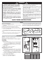
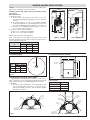
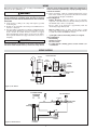
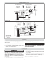
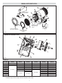
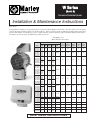
W Series
(Model C)
Corrosion Resistant Heater
Installation & Maintenance Instructions
Dear Owner,
Congratulations! Thank you for purchasing this new heater by Marley Engineered Products. You have made a wise investment
selecting the highest quality product in the heating industry. Please carefully read the installation and maintenance instructions
shown in this manual. You should enjoy years of efficient heating comfort with this product from Marley Engineered Products...
the industry’s leader in design, manufacturing, quality and service.
... The Employees of
Marley Engineered Products
Electrical Data (60 HZ)
Model
Volts
W20011CTLS
W20081CTLS
W20041CTLS
W30011CTLS
W30081CTLS
W30041CTLS
W30071CTLS
W50081CTLS
W50041CTLS
W50071CTLS
W500481CTLS
W50083CTLS
W50043CTLS
W500483CTLS
W50063CTLS
W75081CTLS
W75041CTLS
W75071CTLS
W750481CTLS
W75083CTLS
W75043CTLS
W750483CTLS
W75063CTLS
W100041CTLS
W100071CTLS
W1000481CTLS
W100083CTLS
W100043CTLS
W1000483CTLS
W100063CTLS
W125071CTLS
W1250481CTLS
W125083CTLS
W125043CTLS
W1250483CTLS
W125063CTLS
W1500481CTLS
W150083CTLS
W150043CTLS
W1500483CTLS
W150063CTLS
W200041CTLS
W2000481CTLS
W2000483CTLS
W200063CTLS
W2500483CTLS
W250063CTLS
W3000483CTLS
W300063CTLS
W3500483CTLS
W350063CTLS
W3900483CTLS
W390063CTLS
120
208
240
120
208
240
277
208
240
277
480
208
240
480
575
208
240
277
480
208
240
480
575
240
277
480
208
240
480
575
277
480
208
240
480
575
480
208
240
480
575
240
480
480
575
480
575
480
575
480
575
480
575
kW
2.0
3.0
5.0
7.5
10.0
12.5
15.0
19.5
20.0
25.0
30.0
35.0
39.0
Phase
Amps
1
1
1
1
1
1
1
1
1
1
1
3
3
3
3
1
1
1
1
3
3
3
3
1
1
1
3
3
3
3
1
1
3
3
3
3
1
3
3
3
3
3
1
3
3
3
3
3
3
3
3
3
3
16.7
9.6
8.3
25.0
14.4
12.5
10.8
24.0
20.8
18.1
10.4
13.9
12.0
6.0
5.0
36.1
31.3
27.1
15.6
20.8
18.1
9.0
7.5
41.7
36.1
20.8
27.8
24.1
12.0
10.1
45.1
26.0
34.7
30.1
15.1
12.6
31.3
41.7
36.1
18.1
15.1
47.0
41.7
24.1
20.1
30.1
25.1
36.1
30.2
42.1
35.2
47.0
39.2
BTU
Approx.
Approx.
Air Temp. Air Velocity
Rise (˚F) (Ft./Min.)
Air
Volume
(CFM)
Horizontal
Air Throw
(Ft.)
Approx.
Net. Wt.
(Lbs.)
6,824
21
430
405
12
56
10,236
31
430
405
12
56
17,060
40
430
405
12
68
25,590
37
640
590
13
68
34,120
28
800
1180
40
78
42,650
36
800
1180
40
78
51,180
32
900
1330
45
78
68,240
42
900
1330
45
78
85,300
31/42
1110/740
2700/1800
48
90
102,360
31/42
1110/740
2700/1800
48
90
119,420
31/42
1110/740
2700/1800
48
90
133,068
31/42
1110/740
2700/1800
48
90
66,534
SAVE THESE INSTRUCTIONS
!
WARNING
FAILURE TO UNDERSTAND AND FOLLOW THESE
INSTRUCTIONS AND THE “WARNING” NOTES THEREIN
MAY RESULT IN SERIOUS PERSONAL INJURY FROM
ELECTRICAL SHOCK, OR FROM THE HEATER FALLING
DUE TO FAULTY INSTALLATION.
1. This heater is not intended for use in hazardous atmospheres
where flammable vapors, gases, liquids or other combustible
atmospheres are present as defined in the National Electrical
Code. Failure to comply can result in explosion or fire.
4. Do not mount mercury type thermostat directly on unit.
Vibration could cause heater to malfunction.
5. The heater must be mounted at least 7’ above the floor to avoid
accidental contact with the heating elements or fan blade
which could cause injury.
6. Keep at least 5’ clearance in front of the heater. Refer to
Figure 1 for side, top and back clearance requirements.
7. The ceiling mounting structure and the anchoring provisions
must be of sufficient strength to support the combined weight
of the heater and mounting bracket.
2. ELECTRIC SHOCK HAZARD. Disconnect all power before
installing or servicing heater. Failure to do so could result in personal injury or property damage. Heater must be installed by a
qualified person in accordance with the National Electrical Code,
NFPA 70.
8. The wall or mounting surface, and the anchoring provisions
must be capable of supporting the combined weight of the
heater and the mounting brackets cantilevered from the
mounting surface.
3. ELECTRIC SHOCK HAZARD. Any installation involving electric heaters must be performed by a qualified person and must be
effectively grounded in accordance with the National Electrical
Code to eliminate shock hazard.
9. Fan blade rotation must be checked. If airflow is not moving
out through the louvers, interchange any two of the three customer power leads on three-phase units only.
SAVE THESE INSTRUCTIONS
GENERAL
Large rooms require multi-unit installations. Number and capacity of units will be determined by volume of building and square feet
of floor area to be heated. Arrange units to provide perimeter air circulation where each unit supports the air stream from another.
Heater Location Instructions:
Arrange units so their discharge air streams:
A. Are subjected to minimum interference from columns, machinery
and partitions.
B. Wipe exposed walls without blowing directly at them.
C. Are directed away from room occupants in comfort heating.
D. Are directed along the windward side when installed in a building
exposed to a prevailing wind.
EXPOSED
D
EXPOSE
EX
PO
SE
D
EXPOSED
D
SE
Small rooms can be heated by one unit heater. Where two walls are
exposed, the heater should be mounted as shown in Figure A.
D
PO
SE
EX
PO
EX
Locate thermostat on interior partition walls or posts away from
cold drafts, internal heat sources and away from heater discharge air
streams.
Figure A
FIXED MOUNTING (OPTIONAL)
NOTICE — These heaters are designed for wall and ceiling mount.
Other modes of mounting voids factory warranty.
Ceiling
Ceiling
Mounting Heaters with the Standard “L” Brackets (Optional Model FMB1)
Vertical Airflow
1. Height above floor
A. It is recommended that heater only be used with ceiling heights
of 12 feet or greater. Minimum spacing to ceiling is 12 inches,
use 1/2” thread stock (supplied by others) as shown in Figure 2.
B. Mimimum mounting height is 10 feet from floor to bottom of
heater (Figure 2)
2. Spacing to walls
A. Side of case to walls 18”. (See Figure 2.)
Horizontal Airflow (Non-Swiveling)
1. Height above floor
A. In areas where ceiling height is more than 12 feet, recommended
mounting height is approximately 10 feet to underside of heater.
B. For ceiling heights of 12 feet or less, maximum mounting
height is determined by use of the mounting bracket offered for
these heaters. Minimum spacing to ceiling is 9”. (See Figure 1.)
C. In either case the minimum mounting height is 7 feet from
floor to bottom of heater. (Figure 1)
2. Spacing to adjacent walls (See Figure 1).
A. Rear of case to back wall 1-1/2” minimum.
B. Side of case to side wall 8” minimum.
9" Min.
12"
Min
1-1/2"
Wall
Wall
Wal
Wall
B
18"
Min.
A
C
10'' Min.
Floor
Floor
Figure 1
2
Figure 2
kW
A
Dimensions (In.)
B
C
2.5-7.5
10.0-20.0
25.0-39.0
13-1/2
17-1/4
21-1/4
24-1/2
28
32-1/4
15
15-1/8
19-1/2
MOUNTING (UNIVERSAL SWIVEL MOUNTING)
NOTICE — These heaters are designed for wall and ceiling mount.
Other modes of mounting voids factory warranty.
Ceiling
Mounting Heaters with supplied Universal Mounting Bracket
(Swivel Type)
Horizontal Air Flow
1. Height above floor
A. In areas where ceiling height is more than 12 feet, recommended mounting height is approximately 10 feet to underside
of heater.
B. For ceiling heights of 12 feet or less, maximum mounting
height is determined by use of the mounting bracket offered for
these heaters. Minimum spacing to ceiling is 9”. (See Figure 3.)
C. In either case the minimum mounting height is 7 feet from
floor to bottom of heater. (Figure 3)
2. Spacing to adjacent walls (See Figure 3).
A. Rear of case to back wall 8” minimum.
B. Side of case to side wall 8” minimum.
A
Dimensions (In.)
B
C
2.5-7.5
10.0-20.0
25.0-39.0
13-1/2
17-1/4
21-1/4
24-1/2
28
32-1/4
15
15-1/8
19-1/2
9" Min.
8"
Wall
Wall
B
8"
Min.
8" Min.
A
C
7' Min.
Note: For all horizontal air flow applications
If two or more units are operated in the same enclosed air space, their
discharges should be directed to aid in development of mass air movement for uniform heat dispersal.
kW
Ceiling
Floor
Floor
Fl
oorr
Figure 3
Fixed Mounting (Option)
Universal Mounting Brackets (Standard)
6-7/8"
6"
Dimensions (In.)
A Radius
Bolt Size
kW
2 - 7.5
10 - 20
25 - 39
7-3/4
9-1/2
11-1/2
A Typ
9/16" Dia. Hole
(Typ. Pls.)
3/8 to 7/16
3/8 to 7/16
3/8 to 7/16
6"
8"
Figure 4
Mounting Optional Drip Shields (Model WHDS)
Optional stainless steel drip shields are available to mount to the top
surface of the heater case on a horizontally mounted heater in locations
where it may have dirty corrosive liquids dripping from overhead.
1. Mounting
A. Line up the four mounting holes on the shield with the four
holes on the upper half of the heater case and fasten in place
with the four stainless steel bolts, nuts and washers supplied
with the kit. See figure 6.
Figure 5
Shield Identification
Heater Size
Shield Model
2 - 7.5 kW
10 - 20 kW
25 - 39 kW
WHDS-1
WHDS-2
WHDS-3
(3) FLAT
WAHSERS
PLUG
1-4-20 NUT
(UPPER)
1/4-20 Nut
(Lower)
1/4-20 BOLT
WITH DOUBLE
NUT
ADAPTOR
BRACKET
1/4-20 BOLT
1/4-20 NUT
(UPPER)
1/4-20 BOLT
(LOWER)
1/4-20 LOUVER
MOUNTING BOLTS ONE ON EACH SIDE
1/4-20
BOLT
DRIP SHIELD WITH STANDARD
"L" SHAPE MOUNTING BRACKETS
1/4-20 LOUVER
MOUNTING BOLTS ONE ON EACH SIDE
Figure 6
3
DRIP SHIELD WITH UNIVERSAL
MOUNTING BRACKET (SWIVEL TYPE)
WIRING
Note: All electrical wiring must be done according to National Electrical
and local codes by a qualified person.
with their electric heating equipment. Where the consequences of
failure could result in personal injury or property damage, back-up
controls are essential.
4. Heaters rated 5kW - 39kW are equipped with fan delay control.
This control continues fan operation for a short time after elements
are de-energized to dissipate residual heat.
Standard Equipment
• Built-in Thermostat (bulb and capillary type) for automatic
temperature control. The thermostat controls the heating elements and
fan simultaneously to achieve set temperature.
The Lo setting of the thermostat is approximately 40˚F and
the Hi setting is approximately 90˚F.
• Heat-Cool switch (heater on, heater off, fan only) to permit
air flow with or without energizing the heating elements. The switch is
accessible from outside the NEMA 4X enclosure.
! WARNING
ELECTRIC SHOCK HAZARD. Any installation involving electric heaters
must be performed by a qualified person and must be effectively
grounded in accordance with the National Electrical Code to eliminate
shock hazard.
1. Connect heater according to the voltage and frequency specified
on the nameplate.
2. All units are provided with control and power terminal blocks for
customer’s connection.
3. Protection against overheating is provided by an internal automatic thermal cutout (manual reset cutout optional) which opens the
electric circuit if the normal air-flow is restricted or stopped.
Cutout automatically energizes heater on removal of the obstruction. If optional manual reset is tripped, determine cause before reenergizing.
• A pilot light to indicate when heating elements are energized.
Optional Equipment
• Internal fusing
• Manual reset cutout
• Disconnect switch
• For wiring diagram containing options, see label on inside cover
of terminal box
! WARNING
The system designer is responsible for the safety of this equipment
and should install adequate back-up controls and safety devices
WIRING DIAGRAMS
LOCATED IN HEATER
HEATER
M
T3
THRU
BULKHEAD
AUTOMATIC
OVERHEAT
CUTOUT
C1
TERMINAL
BLOCK
(CONTROL)
C2
T3
T3
C1
L1
L1
TERMINAL
BLOCK
THRU BULKHEAD
FITTING
L1
L1
L1
120V 1 PHASE
Figure 7 2, 3kw 120V 1Ø
1PH ELEMENT WIRING
T1 T1
T2 T2
M
BUILT IN THERMOSTAT
T1
T2
RED
IN HEATER
BLK
BRN
BLK
POWER
CONTACTOR
T1
L1
T2
AR CUTOUT
L2
24V
SEC
X1
X2
TRANSFORMER 40VA
H1
H2
PRIMARY
Figure 8 2, 3kw 208-277V 1Ø
FOR VOLTAGE
SEE HEATER
4
C1
C2
TERMINAL BLOCK
(CONTROL)
WIRING DIAGRAMS (cont’d.)
1PH ELEMENT WIRING
3PH ELEMENT WIRING
M
2T 6T
4T
T3 T3 T2
T1 T1 T2
BUILT IN OR REMOTE
THERMOSTAT
T1 T1 T1
T2 T2 T2
IN HEATER
BLK
RED
C1
BLK
BLUE
ORANGE
C2
TERMINAL BLOCK
(CONTROL)
BRN
AR CUTOUT
T3
T2
2T1 4T2
L1
A2
1L1 3L2 5L3
L3
L2
6T3
NC
1
NO C
YELLOW
A1
MOTOR
CONTACTOR
6
WHITE
PINK
2
BROWN
T1
POWER
CONTACTOR
TIME DELAY
BLACK
BLACK
RELAY
24V
BLACK
X1
OMIT FOR 1Ø
SEC
X2
TRANSFORMER
40VA
H1 PRIMARY H2
Figure 9 5kw to 39kw
FOR VOLTAGE AND PHASE
SEE HEATER NAMEPLATE
3PH ELEMENT WIRING
T1 T1 T2
1PH ELEMENT WIRING
M
2T 6T3
T3 T3 T2
GRN/YEL
IN HEATER
FAN OFF
HEAT
ONLY
1
1
RED
GREEN
T2 T2 T2
T1 T1 T1
4T2
G
BUILT IN
THERMOSTAT
2
ORANGE
C1
C2
BRN
2
BLK/WHITE
AR CUTOUT
L1
T2
L2
T3
2T1 4T1 6T3
1L1 3L2 5L3
L3
3
A1
3
PURPLE
A1
NO C
YELLOW
MOTOR
CONTACTOR
6
WHITE
2
TIME DELAY
RELAY
BLACK
BLACK
PINK
24V
BLACK
OMIT FOR 1Ø
Figure 10 3kw to 39kw
Typical Wiring Diagram
with accessories – Three
position switch.
NC
1
BRN
POWER
CONTACTOR
T1
CONTROL TERMINAL
BLOCK
X1
SEC
X2
H1
PRIMARY
H2
TRANSFORMER
40VA
LIGHT BLUE
FOR VOLTAGE AND PHASE
SEE HEATER NAMEPLATE
OPERATION
3. The ambient operating temperature limits are -20˚F to 104˚F
(-29˚C to 40˚C).
With proper installation this heater will provide efficient and
dependable service. Please read the following guidelines to ensure
reliable operation.
! WARNING
1. Do not allow objects such as fabric or other combustible materials
to restrict the airflow through the heater.
2. Heater should not be operated unattended unless adequate controls
and safety devices have been installed.
FIRE HAZARD. To prevent personal injury or property damage, do not
operate heater near combustible objects, restrict airflow or use for
purposes other than described.
MAINTENANCE
! WARNING
nance procedures.
2. Fan motors in these heaters are provided with sealed ball bearings,
factory lubricated, requiring no further lubrication under normal
service conditions.
3. Vacuum or hose off heater with water (at city pressure) before activating for next heating season to remove accumulated dust or lint
which otherwise may smoke or incinerate on initial heat up.
Turn off power to service heater. Do not attempt to service or clean
heater while unit is operating as there is hazard of electric shock,
injury from operating fan, and burns from hot heating elements.
ELECTRIC SHOCK HAZARD. Disconnect all power before installing or
servicing heater. Failure to do so could result in personal injury or
property damage.
1. Turn off heater and allow to cool before performing these mainte-
Note: Do not use high pressure cleaning systems.
5
RENEWAL PARTS IDENTIFICATION
25
22
24
10
DETAIL OF UNIVERSAL
MOUNTING BRACKET
11
9
13
8
ELEMENT
CONFIGURATION
FOR 2 THRU 12.5 KW
HEATERS
11
23
11
ELEMENT CONFIGURATION
FOR 25 THRU 39 KW HEATERS
ELEMENT CONFIGURATION
FOR 15 THRU 20 KW
HEATERS
Figure 11
TERMINAL BOX COMPONENT LAYOUT
40
4
30
6
7
50
12
3
5
75
76
60
12
70
Figure 12
Elements (11)
Heater KW
120 Volt
208 Volt
240 Volt
277 Volt
480 Volt
575 Volt
2
3
5
7.5
10
12.5
15
20
25
30
35
39
118-305471-001
118-305471-006
118-305471-002
118-305471-007
118-305471-011
118-305471-020
118-305471-101
118-305471-110
118-305471-201
118-305471-004
118-305471-009
118-305471-013
118-305471-022
118-305471-103
118-305471-112
118-305471-203
118-305471-209
118-305471-005
118-305471-010
118-305471-014
118-305471-023
118-305471-104
118-305471-113
Not Available
Not Available
118-305471-019
118-305471-028
118-305471-109
118-305471-117
118-305471-207
118-305471-213
118-305471-304
118-305471-309
118-305471-311
118-305471-313
Not Available
Not Available
Not Available
118-305471-024
118-305471-105
118-305471-118
118-305471-208
118-305471-214
118-305471-305
118-305471-310
118-305471-312
118-305471-314
Not Available
Not Available
Not Available
Not Available
Notes: 1. All heaters have three (3) elements except for 2kw heaters which have two (2).
2. Specified voltages are heater voltages. See heater nameplate for heater voltage.
6
RENEWAL PARTS IDENTIFICATION
Mechanical Parts and Cutout – kW Dependent
Heater KW
Fan (9)
Cutout (10)
2 and 3
5
7.5
10 and 12.5
15 and 20
25, 30, 35 and 39
112-027709-018
112-027709-018
112-027709-019
112-027709-021
112-027709-021
112-027568-003
168-053169-105
168-053169-105
168-053169-105
168-053169-105
168-053169-105
168-053169-106
Notes:
Fitting
Kit (13)
168-053169-090
Mounting
Bracket (22)
Louver (23)
Louver
Stop (24)
027-305488-001
027-305488-001
027-305488-001
027-305488-001
027-305488-001
027-305488-002
182-047073-028
182-047073-028
182-047073-028
182-047073-025
182-047073-025
182-047073-035
282-119082-005
Grille (25)
134-027038-007
134-027038-007
134-027038-007
134-027038-008
134-027038-008
134-027038-005
1. See heater nameplate for heater kW
2. Fitting kit (13) includes fitting, gasket, screws and heat shrink tubing.
3. Cutout Kit (10) includes cutout, heat shrink and hardware.
Electrical Parts
Heater
kW
2&3
2&3
2&3
5, 7.5, 10, 12.5, 15 & 20
5, 7.5, 10, 12.5, 15 & 20
5, 7.5, 10, 12.5, 15 & 20
5, 7.5, 10, 12.5, 15 & 20
25, 30, 35 & 39
25, 30, 35 & 39
2&3
2&3
5, 7.5, 10, 12.5, 15 & 20
5, 7.5, 10, 12.5, 15 & 20
5, 7.5, 10, 12.5, 15 & 20
5, 7.5, 10, 12.5, 15 & 20
25, 30, 35, & 39
25, 30, 35, & 39
Heater
kW
Heater Heater
Line Control Htr
Voltage Voltage Phase
120
208-240
277
208-240
277
480
575
480
575
208-240
277
208-240
277
480
575
480
575
120
120
120
120
120
120
120
120
120
24
24
24
24
24
24
24
24
Heater Heater
Line
Control
Voltage Voltage
1
1
1
1 or 3
1
1 or 3
1 or 3
3
3
1
1
1 or 3
1
1 or 3
1 or 3
3
3
Htr
Phase
Contactor
(3)
Not Used
Motor
Relay
(4)
Time Delay
Relay
Transformer
(5)
(6)
Motor
(8)
Plug
(12)
Not Used
315-304252-001
315-304252-003
168-053169-091
315-305252-001
072-304551-008
315-304252-003
315-304252-001
168-053169-092
072-123534-064 072-071847-038 315-304252-003
168-053169-093
315-304252-001
168-053169-094
315-304252-003 303-302177-010 168-053169-095 221-300463-002
Not Used
Not Used
315-304252-002
Not Used
Not Used
315-304252-004
168-053169-091
315-305252-002
315-304252-004
072-304551-002
168-053169-092
072-123534-075 072-071847-039 315-304252-002
315-304252-005
168-053169-093
315-304252-002
168-053169-094
315-304252-005
168-053169-095
Thermostat
(30)
Not Used
Not Used
Not Used
Terminal
Block
(7)
Man. Reset
Cutout
(40)
Not Used
Not Used
Not Used
Disconnect
Switch
(50)
3 Position
Switch
(60)
Pilot Light
GREEN
(70)
Pilot Light
AMBER
(75)
Pilot Light
RED
(76)
213-304688-002
2&3
120
120
2&3
208-240
120
1
2&3
277
120
1
213-304688-007
213-304688-008
5, 7.5, 10, 12.5, 15 & 20
208-240
120
1 or 3
(LED
(LED
(LED
5, 7.5, 10, 12.5, 15 & 20
277
120
1
Replacement
Replacement
Replacement
5, 7.5, 10, 12.5, 15 & 20
480
120
1 or 3
Lamp Per
Lamp Per
Lamp Per
5, 7.5, 10, 12.5, 15 & 20
575
120
1 or 3
213-304688-012)
213-304688-014)
213-304688-005)
25, 30, 35 & 39
480
120
3
25, 30, 35 & 39
575
120
3
2&3
208-240
24
1
2&3
277
24
1
213-304688-009
213-304688-010
213-304688-001
5, 7.5, 10, 12.5, 15 & 20
208-240
24
1 or 3
(LED
(LED
(LED
5, 7.5, 10, 12.5, 15 & 20
277
24
1
Replacement
Replacement
Replacement
5, 7.5, 10, 12.5, 15 & 20
480
24
1 or 3
Lamp Per
Lamp Per
Lamp Per
5, 7.5, 10, 12.5, 15 & 20
575
24
1 or 3
213-304688-011)
213-304688-013)
213-304688-004)
25, 30, 35, & 39
480
24
3
25, 30, 35, & 39
575
24
3
Notes:
1
168-053169-096 168-053169-097
168-053169-098
292-304687-007
40-90˚F
1. See heater nameplate for heater kw, line voltage, control voltage and phase.
2. Thermostat includes compression fitting, knob, indicator label, seal, bulb strap and mounting hardware.
3. Manual reset includes compression fitting, bulb mounting bracket and mounting hardware.
4. Disconnect switch includes handle, face plate, gasket and mounting hardware.
7
LIMITED WARRANTY
All products manufactured by Marley Engineered Products are warranted against defects in workmanship and materials for one
year from date of installation. This warranty does not apply to damage from accident, misuse, or alteration; nor where the connected voltage is more than 5% above the nameplate voltage; nor to equipment improperly installed or wired or maintained in violation of the product’s installation instructions. All claims for warranty work must be accompanied by proof of the date of installation.
The customer shall be responsible for all costs incurred in the removal or reinstallation of products, including labor costs, and shipping costs incurred to return products to Marley Engineered Products Service Center. Within the limitations of this warranty, inoperative units should be returned to the nearest Marley authorized service center or the Marley Engineered Products Service
Center, and we will repair or replace, at our option, at no charge to you with return freight paid by Marley. It is agreed that such
repair or replacement is the exclusive remedy available from Marley Engineered Products.
THE ABOVE WARRANTIES ARE IN LIEU OF ALL OTHER WARRANTIES EXPRESSED OR IMPLIED, AND ALL IMPLIED WARRANTIES OF MERCHANTABILITY AND FITNESS FOR A PARTICULAR PURPOSE WHICH EXCEED THE AFORESAID
EXPRESSED WARRANTIES ARE HEREBY DISCLAIMED AND EXCLUDED FROM THIS AGREEMENT. MARLEY
ENGINEERED PRODUCTS SHALL NOT BE LIABLE FOR CONSEQUENTIAL DAMAGES ARISING WITH RESPECT TO THE
PRODUCT, WHETHER BASED UPON NEGLIGENCE, TORT, STRICT LIABILITY, OR CONTRACT.
Some states do not allow the exclusion or limitation of incidental or consequential damages, so the above exclusion or limitation
may not apply to you. This warranty gives you specific legal rights, and you may also have other rights which vary from state to
state.
For the address of your nearest authorized service center, contact Marley Engineered Products in Bennettsville, SC, at 1-800-6424328. Merchandise returned to the factory must be accompanied by a return authorization and service identification tag, both available from Marley Engineered Products. When requesting return authorization, include all catalog numbers shown on the products.
HOW TO ORDER REPAIR PARTS
In order to obtain any needed repair or replacement parts, warranty service or technical information,
please contact Marley Engineered Products Service
Center toll-free by calling 1-800-642-HEAT.
470 Beauty Spot Rd. East
Bennettsville, SC 29512 USA
ECR 36653
Part No. 5200-2473-001
10-05