1
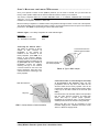
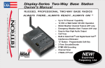
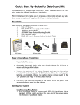
Liberty Radio Extender System USER’S INSTALLATION GUIDE Pub. 14500049 Rev. A 01-05 Liberty Radio Extender System User’s Installation Guide 1 T H A N K Y O U F O R C H O O S I N G R I T R O N ............................................................... Congratulations on your purchase of the Ritron Liberty Radio Extender System. Your new system is the result of Ritron’s 25+ years of designing, manufacturing, and supplying, professional wireless communication systems and products. Ritron wireless products will improve the operation, safety, and profitability of any organization by providing instant voice communications between employees throughout the workplace. This User Installation Guide is specifically designed to help you install and use the Liberty Radio Repeater System. If after following these instructions you are not satisfied with your Liberty Radio Repeater System please contact us. Call, email, or fax us and we’ll do everything possible to make sure you are completely satisfied. Phone: 800-USA-1-USA (800-872-1-872) or 317-846-1201 Fax: 317-846-4978 Email: [email protected] L I B E R T Y R A D I O E X T E N D E R S Y S T E M O V E R V I E W ................................................ The centerpiece of the UHF Liberty Radio Extender System is the ultra compact Ritron Liberty UHF Repeater (model RLR-460) and the included Liberty antenna. The UHF Liberty repeater operates in the 450 to 470 MHz FM communications band and has a maximum output power of 2 Watts. The repeater and its antenna receive signals originating from either a portable, base station or callbox on one frequency and simultaneously retransmits (repeats) the signal on a second frequency. Because the repeater “automatically” retransmits the signals it receives, it will operate unmanned. This automatic retransmitting of signals combined with the ability to remotely mount the Liberty antenna in an optimal location, makes the Liberty Radio Extender system a powerful on-site communication system. In general, communication systems that utilize a radio repeater, such as the Liberty repeater, enable radios to achieve better coverage, better penetration and longer range than is possible without a repeater. All radios included in the system have been have been specially programmed to work together as a system. If you wish to add-on additional radios to your system, they must operate in the same frequency band as the Liberty repeater and be capable of repeater operation (see system frequencies below). See page 3 for Ritron “Liberty System” compatible model numbers. • The Liberty Repeater is pre-programmed at the factory and cannot be changed in the field. • The JMX-446D-Liberty portables and JBS-446D-Liberty base station radio each have 10-channel capability. Channels 1 and 2 of these radios are pre-programmed at the factory and cannot be changed in the field. However, you can re-program the contents of channels 3 - 10. See the included user manual for field programming instructions. • (Optional Radio - not included with system) The Ritron OUTPOST XT Callbox, model RQX-451-XTLIBERTY (1 channel). It is also pre-programmed at the factory and cannot be changed in the field. It will only communicate through the Liberty repeater. DEFAULT SYSTEM FREQUENCIES TRANSMIT RECEIVE TONE RLR-460 Liberty Repeater 452.9875 MHz 457.9875 MHz 97.4 Hz JMX-446D-Liberty Ch1. (repeater) Ch2. (direct radio-to-radio) 457.9875 MHz 452.9875 MHz 452.9875 MHz 452.9875 MHz 97.4 Hz 97.4 Hz JBS-446D-Liberty Ch1. (repeater) Ch2. (direct radio-to-radio) 457.9875 MHz 452.9875 MHz 452.9875 MHz 452.9875 MHz 97.4 Hz 97.4 Hz FCC L I C E N S I N G ......................................................................................... Your Liberty Radio Extender System does require an FCC license for operation. Included with the system is a cover letter explaining the process and a worksheet application and signature page for you to complete, sign and return to Ritron along with a check covering the cost of processing the application and the FCC license. 2 Liberty Radio Extender System User’s Installation Guide T H E L I B E R T Y R A D I O E X T E N D E R S Y S T E M ......................................................... YOUR LI BERTY SYS TEM CONSISTS OF THESE ITEMS: RLR-460 (1) UHF Ritron Liberty Radio Repeater, Narrowband, w/ model RPS-1A, 110VAC Power supply JBS-446D-LIBERTY (1) UHF Ritron Jobcom Base Station with power supply, specially programmed for use with the Liberty Repeater JMX-446D-LIBERTY (4) Four UHF Ritron Jobcom Portable Radios, specially programmed for use with the Liberty Repeater RAM-45 (1) UHF Antenna, magnetic mount, w/ 12ft. co-axial cable with BNC connector 02100380 (1) Adaptor, “N” male to BNC male connector. (may already be attached to repeater) BCJS-4AD (1) 4-Unit Drop-In Charger w/ RPS1A 110VAC power supply 14500050 (1) FCC License Application Worksheet and Signature Page A D D I T I O N AL R AD I O P R O D U C T S T O A D D T O Y O U R L I B E R T Y R AD I O E X T E N D E R S Y S T E M : In addition to the radios listed above, the following radio products are also available. RQX-451-XT-LIBERTY OutPost XT Callbox, 1 Watt, 1 channel, specially programmed for use with the Liberty Repeater. Ideal at the receiving dock door, gate entrances, parking lots, golf courses, on the plant floor. JBS-446D-LIBERTY Spare UHF Ritron Jobcom Base Station, specially programmed for use with the Liberty Repeater RQA-450-L Quick Assist Shopper Callbox. Transmits your own stored voice message over the radio system anytime the button is pressed. (Request Liberty System programming when ordering) Liberty Radio Extender System User’s Installation Guide JMX-446D-LIBERTY Spare UHF Ritron Jobcom Portable Radio, specially programmed for use with the Liberty Repeater. See the user manual for a variety of useful earbud, headset and speaker microphone accessories. RQT-450 Quick Talk Wireless Voice Alarm Reporter. Provides 24/7 monitoriing of any switch or sensor. Transmits your own stored voice message any time the switch opens or closes over your 2-way radio system. (Request Liberty System programming when ordering) 3 H O W T H E L I B E R T Y R E P E A T E R S Y S T E M W O R K S ............................................... Channel 1 - Used for “On-Site” communications. Liberty programmed portable and base station radios (if within range of the Liberty repeater and its antenna) will communicate through the Liberty repeater. (Optional OUTPOST XT Callbox) – Single channel callbox. Operates only through the repeater. Liberty Repeater The Liberty Repeater and especially the installation location of its antenna are the most important pieces of your system. The location of the antenna is critical to achieving optimal radio coverage. When properly installed and connected to the Ritron Liberty Radio Repeater, you will be able to extend the range and coverage of your Liberty programmed 2-way radios*. Base or Portable Radio on Ch 1 Base or Portable Radio on Ch 1 2-Way communication 1-Way communication *Radios MUST be specially programmed to operate with the Liberty Radio Repeater. Channel 2 – Used for “Off-Site” communications. Liberty Repeater Liberty programmed portable and base station radios communicate direct, radioto-radio, NOT through the repeater. They will also hear any other repeater communication. Base or Portable Radio on Ch 2 Base or Portable Radio on Ch 2 One radio on Channel 1 and the other on Channel 2 - This combination is possible, but NOT recommended. The radio on Channel 1 will talk through the repeater to the Channel 2 radio, but will only hear the Channel 2 radio directly, radio-toradio. The radio on Channel 2 will talk directly (radioto-radio) to the Channel 1 radio, but will only hear the Channel 1 radio from the repeater. Important point to remember: The radios will always hear the repeater when on Channel 1 or on Channel 2. 4 Base or Portable Radio on Ch 1 Liberty Repeater Base or Portable Radio on Ch 2 Liberty Radio Extender System User’s Installation Guide S T E P 1: A R A D I O C O V E R A G E S I T E S U R V E Y .................................................... THIS WILL REQUIRE 2 PEOPLE AND 2 CHARGED RADIOS. BEFORE permanently installing the antenna for the Liberty Repeater we recommend that you do a “radio coverage site survey” to insure optimal radio range and coverage PREPARING FOR THE RADIO COVERAGE SITE SURVEY: 1. Charge the radio batteries for at least 12 hours. 2. When charged, make sure both radios are set to Channel 2. Note: Since the antenna and the Liberty repeater are not yet installed, you will need to use channel 2 of the portable radios to communicate. Channel 2 is programmed for direct radio-to-radio communication, NOT through the repeater. CONDUCTING THE RADIO COVERAGE SITE SURVEY: Every application is different, and therefore, no “single” rule applies when it comes to where to install the antenna for optimal coverage. In general, the antenna for the Liberty Repeater is the “pivot” point for all communication for radios operating on channel 1. You will need to try to optimize the location of the Liberty antenna in order to reduce obstructions and the distance the radio signal must travel in order to get from any point in the desired coverage area to the Liberty antenna. We recommend that you start by first attempting to install the Liberty ANTENNA (NOT the repeater) “in the center” of the desired coverage area, this reduces the distance the radio signal must travel by ½. If you’re attempting to cover a high rise building (e.g. 15 floors), go to a location half way up (e.g. 7th floor), and in the center of the building. As noted below, you may have to try several locations before finding the best location for the Liberty antenna. 3. Person #1 will take one portable radio and go to the location you would “most likely” install the antenna for the Liberty Repeater (see FIG-1 and FIG-2). This person will “simulate” the type of coverage you can expect, IF, the antenna for the repeater were installed in this location. If necessary, position this person on a ladder to more accurately mimic the height you intend to mount the antenna. BE ADVISED – you may have to try several heights and/or locations before settling on the location you like best. 4. While person #1 remains stationary, person #2 will take the second radio and “walk the site”. While “walking the site” you must attempt to maintain radio contact periodically with person #1. This survey process will reveal whether or not radio coverage is acceptable IF you install the antenna at the person #1 location. Generally speaking, coverage will be slightly better when the repeater and the included antenna are permanently installed. If coverage is inadequate, Person #1 will need to relocate to a new location and repeat the process until range and coverage are optimized. 5. For sites where coverage is desired in multiple buildings, such as an office complex, external mounting of the antenna may be required. Before considering an external installation of the antenna, a site survey should be attempted with person #1 positioned inside a centrally located building at the highest possible elevation (see FIG-3). Person #2 will “walk the site”, communicating with person #1 from inside all buildings and at all outside areas where radio coverage is desired. CONSIDERATIONS: • Don’t forget that the antenna cable is only 10 ft. long. You will need to run power to and mount the Liberty repeater within at least 10 ft. of the antenna location you select. • Typically, the higher the antenna the better but, NOT always. • Every site is different. Thick, reinforced concrete, steel walls and vertical fire panels in ceilings can work to block the penetration of radio signals creating dead spots. • You may want to gradually lower the height of the antenna and/or its location and repeat your site survey to see if coverage improves. • It is best to only change one variable at a time e.g. antenna height or location, then repeat the survey process and compare results. Liberty Radio Extender System User’s Installation Guide 5 Person #1 remains in a fixed, central location, possibly on a ladder to simulate the location of the repeater antenna. 2 2 2 2 2 2 FIG-1: Large Single Level Building Large Warehouses – Manufacturing Plants Discount or Department Stores Person #2 “walks the site”, stopping frequently to communicate with person #1 at the fixed, central location. 2 2 Person #1 remains in a fixed location, centrally located on a floor about ½ way up the building. 2 2 2 2 Person #2 “walks the site”, stopping frequently on each floor to communicate with person #1 at the fixed location. FIG-2: Multi-level Building Hospitals – Office Buildings - Hotels – Department Stores 6 Liberty Radio Extender System User’s Installation Guide 2 2 2 2 2 2 Alternative locations for person #1 1 Alternative locations for person #1 2 Person #2 “walks the site”, talking to person #1 from within each building and from the perimeter of the outside coverage area. 2 Person #1 remains in a fixed location on the top floor of a centrally located building. 2 FIG-3: Multiple building site survey R A N G E A N D C O V E R A G E E S T I M AT E S W I T H A N T E N N A I N S T A L L E D I N S I D E B U I L D I N G .. OUTSIDE RANGE AND COVERAGE ESTIMATES Antenna installed 25 ft. high, inside building 1 mile 1 mile 2 miles • • • Line-of-sight, Liberty antenna to portable/base station or callbox. No obstructions (e.g. hills, mountains, buildings etc.) minimal foliage. Antenna height is 25 ft. above ground. IN-BUILDING RANGE AND COVERAGE ESTIMATES • • • 500,000 sq ft. 400,000 sq ft. 20 floors Note: open warehouse, metal building with Liberty antenna 20 ft. of higher. reinforced concrete building multi-level building Per FCC regulations pertaining to the frequency of the Liberty repeater, the Liberty antenna cannot be placed higher than 75 ft. above the ground Liberty Radio Extender System User’s Installation Guide 7 S T E P 2: I N S T A L L I N G T H E M A G N E T I C M O U N T A N T E N N A F O R T H E L I B E R T Y R E P E AT E R .............................................................................................................................. The (RAM-45) magnetic mount Liberty antenna should be installed in the best location determined from Step 1 of “The site survey”. For the Liberty antenna to function properly the antenna’s magnetic base MUST be attached to a piece of metal (i.e. steel or iron). The antenna comes with 10 feet of attached co-axial cable* so you can remotely locate the antenna up to 10 feet away from the repeater. The antenna cable MUST run directly away from the Liberty Repeater (See FIG-8). The antenna should be mounted at least 7 feet away from the repeater itself. * Do NOT attempt to cut, shorten or splice this cable in any way. For best performance the magnetic mount antenna must be: • Mounted on a metal surface e.g. steel or iron. This metal mounting surface MUST be at least 2 feet square with the antenna positioned in the center. The antenna’s internal magnet will secure it to the surface. Do NOT place adhesives between the bottom of the antenna mounting surface and the metal mounting surface itself. • Orient the antenna so that the element itself is vertical (See FIG-4). This will match the vertical polarization of the companion Liberty system radios. The antenna can be mounted upside down with no affect on performance. Just make sure the antenna element is vertical. • Mounted away from other metal objects, walls, and structures. Avoid surrounding the antenna or “shielding” it by locating it too closely to metal walls, inside an elevator shaft, in recessed girders, firewalls or ceilings (See FIG-5). • Mounted at least 7 ft. away from the Liberty Repeater. Good antenna installation Too close to metal structure In recessed girders FIG-4: Antenna Orientation Not vertically mounted Too close to Liberty repeater FIG-5: Antenna Installation 8 Liberty Radio Extender System User’s Installation Guide S T E P 3: M O U N T I N G T H E L I B E R T Y R E P E A T E R ................................................ Once you’ve picked a location for the (RAM-45) Antenna you will need to consider how you will mount the Liberty radio repeater: Make sure the antenna cable will reach the location you’ve selected. The Liberty Repeater MUST be mounted INDOORS and/or in a CLIMATE CONTROLLED environment. Although it can be operated over a wide temperature range (-22 F to 120 F), it is NOT waterproof or waterresistant. Do not expose to moisture or direct heat. Mount the Liberty Repeater to a suitable surface using fasteners through the holes on each end of the repeater. The actual orientation of the unit and the surface to which it is mounted should not have an impact on its electrical performance. See FIG-8 “Proper Routing of Antenna and Power Cable”. Indicator Lights – The Liberty Repeater has 2 LED indicator lights. Description Pwr - Repeater is “ON” TX - Transmitter Is Activated LED Color Green Red Connecting the Antenna Cable – The Liberty kit includes an N-type adapter to BNC connector (# 02100380). It may already be installed on the connector of the Liberty Repeater. (See FIG-6 for a picture of this antenna adapter). Carefully attach the end of the RAM45 antenna cable to the matching end (A) (See Figure 6) of the adapter (# 02100380). Connect the adapter matching end (B) to the antenna connector located on the end of the Liberty Repeater. Take care not to cross thread when connecting to the Liberty repeater. Seal cable entrance Drip loop Connect this end to the RAM-45 Antenna Cable Connect this end to the Liberty Repeater FIG-6: N-Type to BNC Adapter If the antenna cable is routed through an area likely to be exposed to the elements, make sure that precipitation does not drip down the cable into the structure and/or into the Liberty repeater. This can be prevented by sealing the cable entrance and/or putting a drip loop on the cable outside of the structure (see FIG-7) If the antenna is to be mounted outdoors it is imperative that the entire antenna connection be sealed with silicon seal tape to provide proper operation. Regardless of the antenna used, it is always best to weatherproof the antenna connection using seal tape. FIG-7: Outside Antenna Cable Installation Silicon seal tape can also be purchased at most Industrial Supply Stores, Hardware and Home Center Stores, or Electronic Supply Stores. Liberty Radio Extender System User’s Installation Guide 9 S T E P 4 - C O N N E C T I N G P O W E R T O T H E L I B E R T Y R E P E A T E R ............................. NOTE: DO NOT CONNECT POWER TO THE LIBERTY REPEATER UNLESS ANTENNA IS CONNECTED TO REPEATER AND POSITIONED AT LEAST 7 ft. FEET AWAY! Plug the included Ritron power supply cube model RPS-1A into a source of 110 VAC and route the cable from the RPS-1A wall cube to the Liberty Repeater jack labeled “DC IN”. The unit will automatically “power up” as soon as the power supply is connected to the Liberty repeater. The “green” LED on the unit will light indicating the unit is “ON”. The cable from the power supply should be routed in a straight line (see FIG-8 “Proper Routing of Antenna and Power Cables”. The power cable plugs into the Liberty Repeater in the jack labeled “DC IN”. FIG-8: Proper Routing of Antenna and Power Cables WIRELESS COMMUNICATIONS PRODUCTS and SYSTEMS RITRON, INC. ∙ P. O. Box 1998 Carmel, IN 46082 Phone: 317-846-1201 ∙ Fax: 317-846-4978 Email: [email protected] ∙ Web: www.ritron.com 10 Liberty Radio Extender System User’s Installation Guide