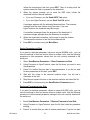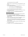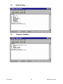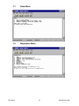
1
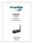
NL6000 Wireless Modem
NL6000 User Manual
Rev 1.1
WWW.RFNEULINK.COM
Copyright
Copyright © 2003 by RF Neulink. This manual may be reproduced for distribution with
the NL6000 as long as the manual remains intact, in its entirety, with all appropriate
Copyright, Intellectual property, and Trademark notices.
This product contains intellectual property and copyrighted material owned by RF
Neulink. Unless expressly agreed to in writing, no one may copy, disassemble, or
distribute in any form, any computer readable information contained within this product,
and in particular information contained within the EEPROM, EPROM, or ROM memory
circuits. All rights, title, and copyrights to the software or firmware in this product are
owned by RF Neulink.
NL6000 is a registered trademark of RF Neulink, a division of RF Industries. RF
Neulink reserves all rights not expressly granted to the purchaser of this product.
Notice:
The information in this document is subject to change without notice.
RF Neulink
7610 Miramar Road
San Diego, CA 92126
858.548.6340
[email protected]
www.rfneulink.com
RF Neulink
2
NL6000 User Guide
TABLE OF CONTENTS
1.
2.
3.
4.
5.
6.
Product Overview ....................................................................................................... 6
1.1. Features ............................................................................................................. 7
Regulatory Information ............................................................................................... 9
Specifications ............................................................................................................ 11
Hardware Installation and Operation ......................................................................... 13
4.1. Parts Description ............................................................................................... 13
4.2. Power Connections ......................................................................................... 13
4.3. Serial Port ........................................................................................................ 13
4.4. Antenna Connection ........................................................................................ 15
4.5. LEDs ............................................................................................................... 15
4.6. Operation ......................................................................................................... 15
4.7. Technical Support ........................................................................................... 16
Software Configuration ............................................................................................. 16
5.1. Prerequisites... .................................................................................................... 16
5.2. Preparation ...................................................................................................... 16
5.3. Unique Data Requirements for a Base Station ............................................... 17
5.4. Source and Destination Addressing ................................................................. 17
5.5. Behavior of Repeater Units ............................................................................. 18
5.6. Packet Data Options ....................................................................................... 21
5.6.1. Transmission Mode ............................................................................ 23
5.6.2. Maximum Packet Size ........................................................................ 24
5.6.3. Over-the-Air Data Rates ..................................................................... 24
5.6.4. Acknowledgements ............................................................................ 24
5.6.5. Carrier Sense Multiple Access ........................................................... 25
5.7. Serial Connection to an I/O Device ................................................................. 25
5.7.1. Basic Serial Parameters ...................................................................... 25
5.7.2. Flow Control ........................................................................................ 25
5.7.3. DCD Mode ........................................................................................... 26
5.7.4. Pre- and Post-Data DCD Time ............................................................. 26
5.8. Planning the RF Channel ................................................................................... 26
5.9. Factory Default Parameters............................................................................... 26
Procedures . ................................................................................................................ 27
6.1. General Procedures ........................................................................................... 28
Entering Programming Mode .......................................................................... 28
Setting the Program Mode .............................................................................. 28
Saving Configuration Changes to Flash Memory ............................................ 28
Saving Configuration Changes Temporarily .................................................... 28
Reverting to the Prior Configuration ............................................................... 28
Returning to the Previous Menu ..................................................................... 29
Displaying the Configuration Summary Window ............................................. 29
6.2. Radio Network Setup ...................................................................................... 30
Setting the Unit Type ....................................................................................... 30
Setting the Unit ID (MYID) ............................................................................... 30
Setting the Target Unit ID (TOID)........................................................................ 30
Setting the Active Channel .............................................................................. 30
Setting the Receive Frequency ........................................................................ 30
Setting the Transmit Frequency ....................................................................... 30
RF Neulink
3
NL6000 User Guide
7.
8.
6.3. Serial Connection Setup .................................................................................. 31
Setting the Baud Rate......................................................................................... 31
Setting the Data Bits ....................................................................................... 31
Setting the Stop Bits ........................................................................................ 31
Setting the Transmit Character Timeout .......................................................... 31
Setting the Flow Control Option ....................................................................... 31
Setting the DCD Mode ..................................................................................... 31
Setting the Pre-Data DCD Time ....................................................................... 32
Setting the Post-Data DCD Time ..................................................................... 32
6.4. Data Setup... ....................................................................................................... 32
Setting the Maximum Packet Size ................................................................... 32
Setting the Packet Mode .................................................................................. 32
Setting the Data Rate ...................................................................................... 33
Setting the Request ACKs Option ................................................................... 33
Setting the Contention Option ......................................................................... 33
Setting the Max Retries Option ........................................................................ 33
6.5. Repeater Setup ................................................................................................... 34
Selecting the Repeater Entry to Edit ............................................................... 34
Setting the Repeater Trigger ............................................................................ 34
Setting the Repeater Trigger ID ......................................................................... 35
Setting the Repeater Transmit Channel .......................................................... 35
Setting the Repeater Transmit Delay .............................................................. 35
6.6. File Management ............................................................................................ 35
Downloading a Software Upgrade . .................................................................. 35
Saving Parameters to Disk .............................................................................. 36
Restoring Parameters from Disk ....................................................................... 36
Restoring Default Parameters ......................................................................... 37
Menu Quick Reference ............................................................................................. 38
7.1. Main Menu ....................................................................................................... 38
7.2. Summary Window ........................................................................................... 38
7.3. Serial Menu ..................................................................................................... 39
7.4. DCD232 Sub-Menu............................................................................................ 39
7.5. Network Menu .................................................................................................. 40
7.6. Repeater Sub-Menu .. ......................................................................................... 40
7.7. Radio Menu ..................................................................................................... 41
7.8. Diagnostics Menu ............................................................................................ 41
7.9. Save/Restore Parameters Menu......................................................................... 42
Other Considerations ................................................................................................... 43
8.1. Duty Cycle ....................................................................................................... 45
8.2. Troubleshooting ............................................................................................... 43
8.2.1. Use a Good Antenna ........................................................................... 43
8.2.2. Three-wire Interface ............................................................................. 43
8.2.3. Hardware Flow Control
..................................................................... 43
8.2.4. Use a Fully-Wired RS-232 Cable ......................................................... 44
8.2.5. Use a Slower Baud Rate . .................................................................... 44
8.2.6. Use a Faster Baud Rate ...................................................................... 44
8.2.7. Unit Does Not Enter Programming Mode ............................................ 44
RF Neulink
4
NL6000 User Guide
Appendix A Diagnosing and Correcting Performance Problems ....................................
Setting the Power Value...............................................................................................
Setting the Frequency Trim (includes setting Power) ...............................................
Setting the Deviation and Balance ............................................................................
Setting the Receive Gain..............................................................................................
Appendix B - Factory Default Parameters ........................................................................
Index ...................................................................................................................................
RF Neulink
5
45
45
45
46
47
49
50
NL6000 User Guide
1. Product Overview
The RF Neulink NL6000 is an integrated radio modem that provides reliable bidirectional RS-232 data transmissions on a land mobile radio channel. Configurable
RS-232, radio, and packet data parameters provide the NL6000 with the flexibility
necessary for use in both simple and complex networks.
In its simplest configuration, the NL6000 transmits wireless data from one modem to
another to send instructions and receive a response. In many cases, the factoryconfigured default parameters make the unit ready to use after just setting two address
IDs. Figure 1 shows a simple system to transmit data between two terminals.
Figure 1: Use the NL6000 in a Simple Configuration
In a more sophisticated configuration, the NL6000 provides wireless communication
between multiple units in a network. A unit configured as a base station can transmit
instructions to multiple remote units and collect responses from those remotes for
analysis and management reporting. Configuration of multiple units is a simple task
using the menu-driven user interface. Figure 2 shows a system for maintaining the
water level for a number of water tanks.
Figure 2: Use the NL6000 in a Multi-Unit Network
RF Neulink
6
NL6000 User Guide
The NL6000 s powerful and efficient packet communications protocol provides a solution to
many of the problems affecting conventional wireless data networks. Bursts of noise, RF
interference, inter-modulation, overload, and signal fade can corrupt and interrupt radio data
links. The NL6000 eliminates these problems through the use of advanced technologies
including sophisticated forward error correction technology.
The NL6000 can transmit in any of the following frequency ranges:
• VHF 136
162 MHz
• VHF 148
174 MHz
• VHF 216
235 MHz
• UHF 400
420 MHz
• UHF 450
470 MHz
1.1. Features
The following list highlights the primary features of the NL6000:
Product Reliability
The NL6000 makes extensive use of Digital Signal
Processing (DSP) technology resulting in outstanding
performance under adverse environmental conditions.
Data Reliability
Advanced signaling end error control technologies
provide exceptional performance under poor channel
conditions.
RF Data Rate
The NL6000 can transmit or receive at over-the-air rates
of 12,000 bps within narrowband or 22,050 bps within
wideband channels.
Protocol Flexibility
The NL6000 provides three data transmission modes
resulting in peak system performance for a wide range of
data communication scenarios.
Easy Use Interface
An easy to follow menu-based user interface makes
configuring the NL6000 a simple task.
Base Station Configuration
The NL6000 can be configured as a remote or a base
station. A remote transmits data to a specific unit or group
of units. A base station transmits data to multiple units or
groups.
Repeater Configuration
In areas where you lack a reliable path, you can
configure an NL6000 unit as a repeater to reach a
hidden unit. This feature can fill in RF blind spots or
extend the usable range of the system s desired
coverage area.
RF Neulink
7
NL6000 User Guide
Single and Multi- Point
Addressing
An NL6000 can be configured to transmit to a single unit,
a group of units, or to broadcast to all units within range.
Acknowledgement
The NL6000 can be configured to request an
acknowledgement (ACK) from the destination modem
with each transmission. If it does not receive an ACK,
the unit can retransmit a specified number of times.
Auto-Transmit
The NL6000 will automatically trigger transmission of data
over the RF link: The NL6000 will wait for characters to
arrive via the serial port in order to completely fill a
packet size as defined under Network/Max Packet Size
before transmitting. The typical default setting for TX
CHAR TIMEOUT is 100 and MAX PACKET SIZE is 300.
This will give you a reasonable response time between
serial data arrival and transmitting data. The MAX
PACKET SIZE should be set based on your applications
typical maximum packet size.
Configuration Templates
The NL6000 software allows you to save a configuration
as a template and download the parameters in that
template to other units that share the same configuration.
This saves time when configuring a large network. Care
should be taken in maintaining the Diagnostics
configuration settings. These settings are normally
factory set using radio test equipment and are unique to
each NL6000 radio
RF Neulink
8
NL6000 User Guide
2. Regulatory Information
Notice
It is the responsibility of the user of this equipment to obtain the proper FCC license
to operate this product on the desired channel of operation.
FCC Part 15
This product complies with Part 15 of the FCC rules and regulations (Code of
Federal Regulations 47CFR Part 15). It may not be modified without the expressed
consent of RF Neulink. Modification of this product could void the user s
authorization to use the product.
FCC Part 90
The NL6000 has been type accepted for operation by the FCC in accordance with
Part 90 of the FCC rules (47CFR Part 90). See the label on the unit for the specific
FCC ID and any other certification designations.
FCC Part 101
The NL6000 has been type accepted for operation by the FCC in accordance with
Part 101 of the FCC rules (47CFR Part 101). See the label on the unit for the
specific FCC ID and any other certification designations.
406.0 to 406.1 MHz Operation
The frequency band from 406.0 to 406.1 MHz is reserved for use by distress
beacons. As such, the NL6000 should not be programmed to transmit on any
frequency within this band. Caution should be used when programming frequencies
into the NL6000 to eliminate the possibility of NL6000 users interfering with rescue
operations on this band.
Safety Warning
In order to ensure the safe operation of this radio equipment, the following practices
should be observed.
RF Neulink
•
DO NOT operate radio equipment near electrical blasting caps or in an
explosive atmosphere.
•
DO NOT operate any radio transmitter unless all RF connectors are secure
and any open connectors are properly terminated.
•
DO NOT allow the antenna to come close to, or touch, the eyes, face, or any
exposed body parts while the radio is transmitting.
•
DO NOT operate the radio unless it has been installed and inspected by a
qualified radio technician.
•
DO NOT let children operate transmitter equipment.
9
NL6000 User Guide
3. Specifications
GENERAL SPECIFICATIONS
Dimensions
DC voltage input
Operating temperature
Number of Channels
Number of ID codes
Over-the-air (Tx) data rate
Serial port baud rates
RF input/output connector
Data interface
Serial interface
Mode of operation
Frequency control
Error control
RF Neulink
3.0 in L x 2.6 in W x 1.6 in H
Nominal 10-15 VDC
-30° C to +60° C
64
65,525
12,000 bps or 22,050 bps
1200 bps, 2400 bps, 4800 bps,
9600 bps, 19.2 kbps, 28.8 kbps,
38.4 kbps
SMA-F
9-pin (DB9)
RS-232 async
Simplex or Half Duplex
PLL synthesizer
3 data transmission modes provide
progressively increasing error correction strength
10
NL6000 User Guide
UHF RADIO
SPECIFICATIONS
Model Numbers
NL6000
Transmission frequencies
Current Drain at 12 V:
450-470 MHz & 400-420 MHz
IDLE radio channel
0.2 amps
Receive
0.2 amps
Transmit: 0.5 watts
1.0 amps
Transmit: 1.0 watts
1.2 amps
Transmit: 2.0 watts
1.6 amps
Transmit: 3.0 watts
1.9 amps
Transmit: 4.0 watts
2.2 amps
Transmit: 5.0 watts
2.6 amps
Transmit: 6.0 watts
Transmitter:
3.1 amps
RF power
1 to 6 watts
Modulation
4-FSK with spectral precoder
Frequency stability
1.5 ppm
Channel spacing
12.5 kHz (narrow), 25 kHz (wide)
Channel step size
6.25 kHz UHF
Duty cycle
5% to 75%, depending upon
voltage, power level, and ambient
temperature
50 ohms
RF load impedance
Receiver:
Sensitivity (95% reliability, 500 user
data bytes per packet)
Basic Telemetry Mode 109 dBm
Enhanced Telemetry Mode 115
dBm
Mobile Data Mode 115 dBm
Selectivity
60dB min (narrow), 70dB min (wide)
Intermodulation
70dB min
50 ohms
RF input impedance
RF Neulink
11
NL6000 User Guide
VHF RADIO
SPECIFICATIONS
Model Numbers
NL6000-VHF (148-174 MHz)
NL6000-VHF1 (136-162 MHz)
Transmission frequencies
Current Drain at 12 V:
136-162 MHz, 148-174 MHz
IDLE radio channel
0.2 amps
Receive
0.2 amps
Transmit: 0.5 watts
1.0 amps
Transmit: 1.0 watts
1.3 amps
Transmit: 2.0 watts
1.7 amps
Transmit: 3.0 watts
2.1 amps
Transmit: 4.0 watts
2.4 amps
Transmit: 5.0 watts
2.6 amps
Transmit: 6.0 watts
Transmitter:
2.8 amps
RF power
1 to 6 watts
Modulation
4-FSK with spectral pre-coder
Frequency stability
1.5 ppm
Channel spacing
12.5 kHz (narrow), 25 kHz (wide)
Channel step size
2.5 kHz VHF
Duty cycle
5% to 75%, depending upon voltage,
power level, and ambient temperature
50 ohms
RF load impedance
Receiver:
Sensitivity (95% reliability, 500 user
data bytes per packet)
Basic Telemetry Mode 106 dBm
Enhanced Telemetry Mode 112 dBm
Mobile Data Mode 112 dBm
Selectivity
60dB min (narrow), 70dB min (wide)
Intermodulation
70dB min
50 ohms
RF input impedance
RF Neulink
12
NL6000 User Guide
4. Hardware Installation and Operation
4.1. Parts Description
Figure 3: Parts Description of the NL6000
Part #
(1)
(2)
(3)
(4)
(5)
(6)
4.2.
Description
Antenna Connector
USB Port (used by factory)
Tx/Rx LED
Power Connector
Pwr/USB LED
Serial Port (DB9 Connector)
Power Connections
Connect a 12 VDC power supply to the power connector to provide power
to the NL6000.
Note: If you want to use an external power amplifier, contact the RF
Neulink sales department.
4.3.
Serial Port
The serial port on the NL6000 is a 9 pin female connector.
RF Neulink
13
NL6000 User Guide
The NL6000 is a Data Communications Equipment (DCE) device. Other
equipment that can connect to the NL6000 via the serial port fall into one of
the following categories:
DTE
Data Terminal Equipment (computers, mainframes,
terminals)
DCE
Data Communications Equipment (modems, printers,
other peripherals)
Connect a DTE device to the DB9 connector with a 9-pin male connector
wired one-for-one as shown in Figure 4 and Figure 5.
Figure 4: DTE to DCE Connection
DTE, 9 Pin Male on Computer
DCE, 9 Pin Female on NL6000
Figure 5: Male and Female Connectors with Numbered Pins
RF Neulink
14
NL6000 User Guide
Connect a DCE device to the DB9 connector with a null modem cable wired
as shown in Figure 6.
Figure 6: DTE to DTE Connection
4.4.
Antenna Connection
You must connect a suitable antenna to the RF antenna connection. This
antenna is used for both transmitting and receiving over-the-air
messages.
Caution: Do not operate the radio modem without an antenna.
4.5.
LEDs
Table 1 interprets the two LEDs on the NL6000.
LED
Color
Meaning
Tx/Rx
Red
Transmitting
Green
Receiving a signal on the active channel.
None
Amber Blinking
Not receiving or transmitting
Powered on
None
Powered off
Pwr
Table 1: NL6000 LEDs
Note: If the Rx LED is continuously green, this means an open squelch or
interference problem exists that will inhibit transmissions.
4.6.
Operation
It is the responsibility of the user to obtain the proper FCC license to operate this
product on the desired channel of operation.
RF Neulink
15
NL6000 User Guide
The NL6000 comes factory-configured for the broadcast mode of operation and
tuned and tested on the default frequency of 464.550 MHz (UHF), 154.6000 MHz
(VHF) and 221.5 MHz for the 216-235 MHz band.
The NL6000 operates automatically after you properly install the physical units and
configure the software parameters. In most networks with more than two units, you
must set the MYID and TOID parameters before operation. Sections 5 and 6 discuss
the available software parameters and the procedures for setting them.
4.7.
Technical Support
Telephone support is available Monday through Friday, 7:00 am to 4:00 pm Pacific
Time at (858) 549-6340.
5. Software Configuration
5.1.
Prerequisites
To configure the NL6000, you must connect a computer to the RS232
port and run a terminal emulator such as HyperTerminal or ProComm.
5.2.
Preparation
Plan the network before configuring the parameters that control each
individual unit. The network plan must address the following
questions:
• What is the location of each unit in the network?
• Which units are remotes and base stations?
• Does the network require any repeaters?
• How many frequencies are available?
• Which transmission mode should be used?
You can configure the NL6000 as a remote or a base station. A remote
is limited to transmitting data to a pre-programmed destination. A base
station can transmit data to any remote using a destination ID specified
in the data string it receives from the serial port. See Section 5.3 for
additional detail on the data requirements for a base station.
Assign each NL6000 with a unique address (MYID). If the unit is a
remote, you also assign a destination address (TOID). The destination
address can be specific to a single unit or can include wildcards for
transmitting to a group of units. If the unit is a base station, the
software determines the TOID from the received data string. See
Section 5.4 for examples of addressing and wildcards.
RF Neulink
16
NL6000 User Guide
If a reliable path does not exist between a remote unit and a base
station, you can configure one or more NL6000 units as a repeater to
reach the hidden unit. The repeater can work with both simplex and half
duplex networks. See Section 5.5 for additional detail on the unique
behavior of a repeater unit.
You can select from three radio channel transmission modes that provide
increasing levels of error control. By evaluating the signal strength and
path between two modems, you can select a transmission mode that
results in the best performance. See Section 5.6 for a description of each
transmission mode.
5.3.
Unique Data Requirements for a Base Station
When configured as a base station, there are specific requirements for the
data strings sent through the NL6000 s serial port. Because a base station
is the central point of a network, it must be able to selectively transmit to
any remote. To provide for selective destinations, each data string coming
into the serial port must begin with a colon (:) followed by four ASCII
characters that specify the destination TOID. The data string must
immediately follow the ASCII characters with no pause between them as
in the example:
:ABCD[user data]
5.4.
Source and Destination Addressing
Specify a unique identification number for each NL6000 unit in the
network plan. This number, the MYID, references the source of the data
packet. The TOID is the destination address for the packet, so the TOID is
the MYID of the unit for which the data is intended. Both the MYID and
TOID are a hexadecimal value from 0000 to FFFF. Figure 7 illustrates
point-to-point addressing.
Figure 7: Point-to-Point Addressing
Use the FF character as a wildcard to designate a group of destination
units. For example, a TOID may be FF56 or 42FF. A packet sent with a
TOID of FF56 is a match to destination units with a MYID of 1256 and
8856. A packet sent with a TOID of 12FF is a match to destination units
with a MYID of 1277 and 1219. A TOID of FFFF is a broadcast to all units.
RF Neulink
17
NL6000 User Guide
Figure 8 shows the use of a wildcard (12FF) to transmit data to multiple
units within range of Unit #1 that have a MYID starting with 12
Figure 8: Addressing with Wildcards
Figure 9 shows the use of a wildcard (FFFF) to broadcast data to all units
within range of Unit #1.
Figure 9: Using Wildcards to Broadcast
5.5.
Behavior of Repeater Units
When configured as a repeater, the unit listens for packets that qualify for
repeating in addition to its normal functions. A unit qualifies a packet for
repeating based upon the TOID or MYID value associated with the
packet. The trigger for repeating a packet from a base station to a remote
is the value in the packet s TOID field. The trigger for repeating a packet
from a remote to a base station is the value in the packet s MYID field.
You can establish up to eight triggers for each repeater unit.
RF Neulink
18
NL6000 User Guide
Consider the following example of a repeater (MYID3000) configured to
repeat packets transmitted from a base station (MYID2000) to a hidden
remote (MYID4203). Unit MYID3000 is configured with a repeater entry
that has a Trigger = TOID and ID = 4203. This entry tells unit MYID3000
to listen for packets that have a destination address of TOID4203. If the
repeater receives a packet matching the criteria, it immediately repeats
the packet. Figure 10 illustrates this scenario.
Figure 10: Repeat from a Base to a Remote
Consider the following example of a repeater (MYID3000) configured to
repeat packets transmitted from a hidden remote (TOID4201) to a base
station (TOID2000). Unit MYID3000 is configured with a repeater entry that
has a Trigger = MYID and ID = 4201. This entry tells unit MYID3000 to
listen for packets that have a source address of MYID4201. If the repeater
receives a packet matching the criteria, it immediately repeats the packet.
Figure 11 illustrates this scenario.
Figure 11: Repeat from a Remote to a Base Station
Because MYID and TOID values may use wildcards, it is possible to set up
a single repeater entry that will repeat all packets destined to a group of
hidden remotes. In Figure 12, a repeater entry with a Trigger = TOID and ID
= 42FF repeats any packet with a destination matching TOID42FF.
RF Neulink
19
NL6000 User Guide
Figure 12: Repeat to Multiple Remotes using Wildcard
Likewise, it is possible to set up a single repeater entry that will repeat
packets received from any member of a group of hidden remotes. In Figure
13, a repeater entry with a Trigger = MYID and ID = 42FF repeats any
packet received from the group of remotes matching MYID42FF.
Figure 13: Repeat from Multiple Remotes using Wildcard
If you plan to use more than one frequency in your network, frequency
planning is important when you use repeaters. Repeaters, like any other
unit, have only one receive frequency. It is important that all units
transmitting data to a repeater transmit on the repeater s receive
frequency (FA), as shown in Figure 14.
Figure 14: Sample Frequency Plan for a Repeater
RF Neulink
20
NL6000 User Guide
In Figure 14, the repeater unit listens on FA for transmissions from both the
base station and the remote. The example shows a half-duplex channel
between the repeater and base station (FA and FB) and a simplex channel
between the repeater and remote (FA only).
If the network plan requires more than one repeater unit to reach the hidden
remote, you can specify a Transmit Delay (msec) to stagger the
transmissions from each repeater. Figure 15 shows a sample network with
two repeaters. Each repeater trigger entry has its own transmit delay.
Figure 15: Sample Network with Two Repeaters
In a scenario with two repeaters, such as Figure 15, determine how to
set the Transmit Delay based upon the following conditions:
•
Is it possible that both repeaters may hear the same transmission?
•
Is it possible for the ultimate destination to hear the transmission
of both repeaters?
If either these conditions is false, you may set Transmit Delay for
both repeaters to zero (0).
If both of these conditions are true, you should set Transmit Delay on one
repeater to a larger value, such as 0080 msec, and you must enable Carrier
Sense Multiple Access (CSMA). See Section 5.6.5 for more information about
CSMA. In this case, the delay must be large enough so the delayed repeater
recognizes that the other repeater has started transmitting.
5.6.
Packet Data Options
5.6.1. Transmission Mode
The NL6000 supports the following three packet transmission modes:
RF Neulink
•
Basic Telemetry mode
•
Enhanced Telemetry mode
21
NL6000 User Guide
•
Mobile Data mode
Table 2 summarizes the characteristics of each transmission mode
Basic Telemetry
Enhanced Telemetry Mobile Data
Mode
Mode
Mode
Spectral Pre-coding Yes
Yes
Yes
Randomization
Yes
Yes
Yes
CRC
Yes
Yes
Yes
FEC
No
Yes
Yes
Interleaving
No
No
Yes
Table 2: Transmission Mode Characteristics
To select the best transmission mode for a unit, consider the following
factors:
•
Signal strength between the unit and its destination unit(s)
•
Reliability of the path between the unit and its destination unit(s)
•
Noise, RF interference, and fading expected on the radio channel
•
Movement of the unit or movement of its surroundings
Each transmission mode is designed to provide a different level of error
control. The level of error control influences the optimum packet size that will
produce the desired throughput. Use the scenarios on the next page to help
determine which Transmission Mode and Maximum Packet Size is best for a
unit.
Note: If you are not sure which mode to use, use Enhanced Telemetry
mode.
You can configure the transmission mode and packet size parameters
differently for each unit in the network. All transmission modes share a
common mode field as part of the packet. This field allows the receiving
modem to determine the mode prior to decoding a received message.
Scenario #1
Description: You have above average signal strength and a reliable path
between the radio modem units. You do not expect noise bursts, RF
interference, or signal fading to corrupt the radio data link.
Best Choice: Basic Telemetry Mode
Because you have a clean channel, use the mode that uses the least
overhead for each packet. Basic Telemetry mode uses error detection only, so
RF Neulink
22
NL6000 User Guide
it contains the least amount of overhead and the highest percentage of user
data in each packet. Basic Telemetry mode provides the highest throughput
on a clean channel.
However, if there is a transmission error, you will lose the entire packet.
Therefore, when using Basic Telemetry mode, use a smaller Maximum Packet
Size so that you lose very little user data if an error does occur. In this
situation, smaller packets have a better chance of getting through.
Why not use Enhanced Telemetry Mode or Mobile Data Mode for this
scenario? If the channel is clean and the signal is strong, there is no need to
use a mode that reduces the percentage of user data in each packet.
Scenario #2
Description: You have average signal strength or a less reliable path
between the radio modem units. You expect occasional corruption on the
radio data link from noise bursts, RF interference, or signal fading.
Best Choice: Enhanced Telemetry Mode
Because you expect the channel to have occasional corruption, use Enhanced
Telemetry mode. In addition to error detection, Enhanced Telemetry mode
uses Reed-Solomon forward error correction for increased transmission
reliability. This mode requires more overhead than Basic Telemetry mode and
lowers the percentage of user data in each packet.
However, because you are less likely to lose data with Enhanced Telemetry
mode than with Basic Telemetry mode, you can use a larger Maximum Packet
Size. A larger packet size can compensate for the lower percentage of user
data in each packet and provide good throughput on an occasionally corrupt
channel.
Why not use Basic Telemetry Mode for this scenario? Basic Telemetry
mode is not useful when you expect a corrupt channel because a single
transmission error will cause a packet failure. Lost packets will degrade
throughput. Basic Telemetry mode cannot recover data errors, so throughput
would be poor.
Why not use Mobile Data Mode for this scenario? Mobile Data mode
requires that the interleaver be filled for each packet. If the data packets are
smaller than the interleaver size, throughput will suffer because the interleaver
is filled prior to transmission. Since fading is not a big issue in this scenario,
the interleaver is not necessary.
Scenario #3
Description: You have fluctuating signal strength and a less reliable path
between the radio modem units. You expect noise bursts, RF interference, or
signal fading to corrupt the radio data link. The remote unit is moving, or it is
located in an area where the surroundings are moving, such as a busy street.
RF Neulink
23
NL6000 User Guide
Best Choice: Mobile Data Mode
Because you expect a corrupt channel, use the mode that has the greatest
amount of error control. Mobile Data mode includes three types of error
control, Reed-Solomon forward error correction, error detection, and a block
interleaver. This mode provides for maximum transmission reliability on a
corrupt channel. Since the packet size is large, any data added to the packet
to fill the interleaver is insignificant.
Because you are more likely to recover from transmission errors with Mobile
Data mode, you can use a large Maximum Packet Size. A larger packet size
can compensate for the lower percentage of user data in each packet and
provide good throughput on a corrupt channel.
Why not use Basic Telemetry Mode for this scenario? Basic Telemetry
mode is not useful when you expect a corrupt channel because it uses error
detection only. Basic Telemetry mode cannot recover data errors, so
throughput would be poor.
Why not use Enhanced Telemetry Mode for this scenario? Enhanced
Telemetry mode provides error correction, but if both the signal strength and
path are poor, you might need to reduce the Maximum Packet Size to
increase reliability. With Mobile Data mode you can increase the Maximum
Packet Size and get better throughput on a very corrupt channel.
5.6.2. Maximum Packet Size
The NL6000 transmits a data packet on the radio channel when the amount of
data in the input buffer is equal to the Maximum Packet Size or when there is
a timeout on the serial port. The maximum packet size is the largest amount of
user data in one RF packet.
5.6.3. Over-the-Air Data Rates
The NL6000 supports two over the air data rates: 12,000 bps or 22,050 bps.
Select the data rate you want to use depending upon the bandwidth you
occupy and your license.
5.6.4. Acknowledgements
The NL6000 can request an acknowledgement (ACK) from the destination
modem with each transmission. If this option is enabled, the unit will
retransmit a packet up to a specified number of times if it does not receive an
ACK. If it does not receive an ACK after the final retry, the unit will transmit the
next packet. You specify the desired maximum number of retries with the Max
Retries option.
Note: When acting as a repeater, the unit never generates an ACK. ACKs
are end-to-end and do not affect the repeater unit.
RF Neulink
24
NL6000 User Guide
5.6.5. Carrier Sense Multiple Access
If a unit s transmit and receive frequencies are the same, it may be helpful to
enable Carrier Sense Multiple Access (CSMA). This option does not allow
transmission of a packet until the channel is free of contention.
5.7.
Serial Connection to an I/O Device
5.7.1. Basic Serial Parameters
The NL6000 can receive data strings from a variety of I/O devices through its
RS232 serial port. Configure the NL6000 serial port parameters based upon
how the I/O device will send data to the unit. The following is a list of the basic
serial parameters you must configure:
•
Baud rate This parameter is the data rate between the I/O device and
the NL6000 modem. Set the baud rate to the rate of the I/O device.
•
Data bits This parameter is the number of bits the I/O device sends in a
byte. The options available are 7 or 8. The NL6000 does not use parity
bits.
•
Stop bits This parameter is the number of bits used for the end of a
byte. The options available are 1 or 2.
•
Transmit Character Timeout The NL6000 transmits a data packet on
the radio channel when there is a timeout on the serial port equal to this
value or when the amount of data in the input buffer is equal to the
Maximum Packet Size.
5.7.2. Flow Control
Prior to configuration of the NL6000, determine if you want to use flow control
to prevent the serial device or modem from overflowing its buffer. If flow
control is desired, two types are available RTS/CTS and XON/XOFF. With
RTS/CTS, the modem monitors the RTS signal to determine when to send
data to the serial device. In addition, the modem asserts CTS when the
modem is ready to accept data from the serial device. RTS/CTS is the
preferred method of flow control, but it requires separate lines for RTS and
CTS. If you cannot use hardware flow control, you may use the XON/XOFF
software option for flow control. This option may only be used for ASCII data
and requires the use of special characters to identify when it is OK to send/
receive data to/from the serial device.
5.7.3. DCD Mode
The DCD Mode parameter identifies how the I/O device interprets the current
state of the modem using the DCD line between the device and the modem. If
the mode is set to Enable, the modem asserts the DCD line when it is
receiving data over-the-air. If the mode is set to Disable, the modem asserts
the line when it is in a normal operating state and negates the line when it is in
RF Neulink
25
NL6000 User Guide
a programming state. If the mode is set to DCD 232, certain I/O devices can
wake up when the DCD signal is asserted and turn off when the signal is
negated.
5.7.4. Pre- and Post-Data DCD Time
Two additional parameters, Pre-Data DCD Time and Post-Data DCD Time,
must be set when using the DCD 232 option. The pre-data time value sets the
number of milliseconds it takes for the device to wake up after the modem
asserts the line. The post-data time value sets the number of milliseconds it
takes for the device to turn off after the modem negates the line. These
settings ensure the modem does not transmit data unless the device is ready.
Figure 16 illustrates the pre- and post-DCD time periods.
Figure 16: Pre- and Post-DCD Time
5.8.
Planning the RF Channel
For each unit in the network plan, you must specify the active channel as well
as receive and transmit frequencies used on that channel. Determine these
radio parameters as part of your network plan.
Each NL6000 unit arrives from the factory tuned and tested on the default
frequency appropriate for that unit. Retuning requires that a qualified radio
technician use the procedures in Appendix A
Diagnosing and Correcting
Performance Problems.
5.9.
Factory Default Parameters
Appendix B provides a list of the default parameters set for each NL6000 unit
at the factory. It also provides a blank column for you to record any custom
values you want to set.
RF Neulink
26
NL6000 User Guide
6. Procedures
This section includes step-by-step procedures for configuring all the parameters that
control the operation of the NL6000. The procedures are grouped into the following
categories:
•
General Procedures
•
Radio Network Setup
•
Serial Connection Setup
•
Data Setup
•
Repeater Setup
•
File Management
Configuration of the NL6000 parameters is easy using the menu-driven user
interface. When you enter programming mode using the terminal emulator, a Main
Menu appears. The procedures in this section assume you always begin at the Main
Menu. The Main Menu appears as in Figure 17.
Figure 17: NL6000 Main Menu
In most procedures, you must enter at least one submenu to perform a task. The
following text is an example of a step that leads you to the correct submenu option:
Select Network ä Unit Type”
This example means that from the Main Menu, you must select the Network option
and then select the Unit Type option from the submenu that appears. Throughout
this section, the arrow (ä) directs you through a series of submenu options.
RF Neulink
27
NL6000 User Guide
6.1. General Procedures
Entering Programming Mode
Perform this procedure when you need to reset any of the existing
configuration parameters for the NL6000.
Note: If the Programming Mode is Disabled, you must perform
this procedure within five seconds of powering on the unit.
1. Open HyperTerminal or Procomm.
2. Type …//
The Main Menu opens.
Setting the Program Mode
The Program Mode parameter determines when the operator can enter
programming mode from operational mode.
1. Select Serial ä Program Mode.
2. Select from the following options:
1-Disabled
Enter programming mode within five seconds of power-on.
Select this option under normal operating conditions to
prevent accidental resetting of parameters.
2-Enabled
Enter programming mode whenever you type the key
sequence …// . There must be a pause before and after the
sequence. Select this option during factory configuration or
during initial configuration of a unit.
Saving Configuration Changes to Flash Memory
Select E - Exit from the Main Menu to save the updated parameter settings to
the unit s flash memory. The unit immediately begins using the new
configuration.
Saving Configuration Changes Temporarily
Select C - Continue from the Main Menu to temporarily save the updated
settings for the current operating session. The configuration is not saved to
flash memory. You can revert to the prior configuration by cycling power to the
unit.
Reverting to the Prior Configuration
Select R - Restart from the Main Menu to ignore the changes you made and
revert back to the prior configuration.
RF Neulink
28
NL6000 User Guide
Returning to the Previous Menu
Press the ESC key at any time to return to the previous menu. The changes
you made up to that point are saved until you leave the Main Menu using
Exit, Continue, or Restart.
Displaying the Configuration Summary Window
Select 1 - Summary from the Main Menu. The summary window appears as in
Figure 18.
Figure 18: Summary Window
RF Neulink
29
NL6000 User Guide
6.2. Radio Network Setup
Setting the Unit Type
1.
Select Network ä Unit Type.
2.
Select from the following options:
1-Base
Configure as a base station. This unit type receives
the TOID from the data packet received through the
serial port.
2-Remote
Configure as a remote. This unit type receives the
TOID from its configuration.
Setting the Unit ID (MYID)
1.
Select Network ä MYID.
2.
Enter a unique identification for the unit. The value must be a
hexadecimal value between 0001 and FFFE. For more information about
addressing and wildcards, refer to Section 5.4.
Setting the Target Unit ID (TOID)
You only need to set this parameter if the Unit Type is Remote. The system
ignores this parameter if the Unit Type is Base.
1.
Select Network ä TOID.
2.
Enter the destination address for packets from this unit. The destination
address is the MYID of the unit for which the data is intended. The value
must be a hexadecimal value in the range 0000
FFFF. For more
information about addressing and wildcards, refer to Section 5.4.
Setting the Active Channel
1.
Select Radio ä Select Active Channel.
2.
Enter the channel assignment for this unit. The value must be a number
in the range 01 64.
Setting the Receive Frequency
1.
Select Radio ä Receive Frequency for Active Channel.
2.
Enter the receive frequency for the active radio channel in MHz. The
value must be a number in the format nnn.nnnn.
Setting the Transmit Frequency
1. Select Radio ä Transmit Frequency for Active Channel.
2. Enter the transmit frequency for the active radio channel in MHz. The
value must be a number in the format nnn.nnnn.
RF Neulink
30
NL6000 User Guide
6.3
Serial Connection Setup
Setting the Baud Rate
1.
Select Serial ä Baud Rate.
2.
Select a baud rate for the connection between the modem and I/O device.
The options range from 1200 to 38400.
Setting the Data Bits
1.
Select Serial Data Bits.
2.
Select the number of data bits per byte sent from the I/O device. The
options are 7 or 8 bits per byte.
Setting the Stop Bits
1.
Select Serial ä Stop Bits.
2.
Select the number of number of bits used to designate the end of a
byte. The options are 1 or 2 bits.
Setting the Transmit Character Timeout
1.
Select Serial ä Transmit Character Timeout.
2.
Enter the expected pause between data strings through the serial port.
The value must be in the range 10 9999 milliseconds.
Setting the Flow Control Option
1.
Select Serial ä Flow Control.
2.
Select from the following options:
1-None
Do not use flow control.
2-RTS/CTS
Monitor the Ready To Send (RTS) signal to determine
when to send data to the serial device and assert CTS to
tell the serial device when it can send data to the
modem.
3-XON/XOFF Use special ASCII characters to determine when to
send/receive data to/from the serial device.
Setting the DCD Mode
RF Neulink
1.
Select Serial ä DCD Mode.
2.
Select from the following options:
1-Enable
In this mode the modem asserts the DCD line when it is
receiving data over-the-air.
2-Disable
In this mode the modem asserts the line when it is in a
normal operating state and negates the line when it is in a
programming state.
31
NL6000 User Guide
3-DCD 232
In this mode, certain I/O devices can wake up when the
DCD signal is asserted and turn off when the signal is
negated. If you select this option, the DCD 232 menu
appears for you to set the Pre-Data DCD Time and PostData DCD Time.
Setting the Pre-Data DCD Time
1.
Select Serial DCD Mode ä Pre-Data DCD Time.
2.
Enter the number of milliseconds it takes for the device to wake up after
the modem asserts the line. The value must be a 3-digit number. The
post-data time value sets the number of milliseconds it takes for the
device to turn off after the modem negates the line
Setting the Post-Data DCD Time
1.
Select Serial ä DCD Mode ä Post-Data DCD Time.
2.
Enter the number of milliseconds it takes for the device to turn off after the
modem negates the line. The value must be a 3-digit number.
6.4. Data Setup
Setting the Maximum Packet Size
1.
Select Network ä Max Packet Size.
2.
Enter the largest amount of continuous bytes of user data you expect
in a single transmission. The value must be in the range 1 1023.
Note: The Packet Mode affects how much user data can be in a
packet. For Enhanced Telemetry and Mobile Data modes, the
maximum will be less than 1023 due to memory constraints. The Max
Packet Size window displays the actual value for these two modes.
Setting the Packet Mode
1.
Select Network ä Packet Mode.
2.
Select from the following options:
1-Basic Telemetry
2-Enhanced Telemetry
3-Mobile Data
RF Neulink
This mode uses a simple Cyclic Redundancy
Check (CRC) for error detection.
This mode is similar to Basic Telemetry
mode, but it includes Reed-Solomon
forward error correction.
This mode uses forward error correction and
a block interleaver for maximum transmission
reliability.
32
NL6000 User Guide
Refer to Section 5.6.1 for more information about each packet mode
Setting the Data Rate
1.
Select Network ä Data Rate.
2.
Select the data rate you want to use depending upon the bandwidth you
occupy and your licenses. The available options are 12,000 bps and
22,050 bps.
Setting the Request ACKs Option
1. Select Network ä Request ACKs.
2. Select from the following options:
1-Enable
When the modem sends data it requests an ACK from
the destination modem. If it does not receive an ACK,
the modem will retransmit up to the number of times
you specify in the Max Retries option.
2-Disable
When the modem sends data it does not request an
ACK from the destination modem.
Setting the Contention Option
1. Select Network ä Contention.
2. Select from the following options:
1-None
Do not use contention to determine when to transmit.
2-CSMA
Enable Carrier Sense Multiple Access (CSMA) so that
transmission waits until the channel is free of contention.
This option is helpful if a unit s transmit and receive
frequencies are the same.
Setting the Max Retries Option
You only need to set this parameter if the Request ACKs option is enabled.
The system ignores this parameter if it is disabled.
1. Select Network ä Max Retries.
2.
RF Neulink
Enter the greatest number of times you want to retransmit if you do not
receive an ACK response. The value must be in the range 1 9.
33
NL6000 User Guide
6.5.
Repeater Setup
Each NL6000 unit may have up to eight repeater entries. Each repeater
entry includes a trigger, trigger ID, transmit channel, and transmit delay
value. If a unit does not act as a repeater, do not set up any repeater
entries. For more information about setting up a repeater unit, refer to
Section 5.5
Table 3 shows how to set up the Trigger and ID values for each type of
repeater trigger.
Trigger
Field
ID Value
Use
MYID
nnnn (hex)
Used to repeat a packet from a remote to a base
station. The ID value is the MYID of the remote, or
group of remotes if using a wildcard.
TOID
nnnn (hex)
Used to repeat a packet from a base station to one or
more remotes. The ID value is the TOID of the remote,
or group of remotes if using a wildcard.
Table 3: Setup of Repeater Trigger Fields
Selecting the Repeater Entry to Edit
1.
Select Network ä Repeater ä Select Repeater Entry.
2.
Enter the number assigned to the repeater entry you want to set or edit.
Repeater entries are assigned a number in the range 1 8. After you
select an entry number, the system displays the current parameter
settings for that repeater entry.
3.
Press ESC to return to the Repeater menu where you can set any of the
four repeater parameters.
Setting the Repeater Trigger
RF Neulink
1.
Select Network ä Repeaterä Trigger.
2.
Select from the following options:
1-MYID
Trigger the repeater function for packets addressed with a
MYID equal to the ID value. Set the trigger ID to the MYID
of the remote unit from which you want to repeat packets.
Refer to Table 3.
2-TOID
Trigger the repeater function for packets addressed with a
TOID equal to the trigger ID value. Set the trigger ID to the
TOID of the destination unit. Refer to Table 3.
34
NL6000 User Guide
Setting the Repeater Trigger ID
1.
Select Network ä Repeater ä ID.
2.
Enter the value of the trigger ID as follows:
•
If the Trigger is MYID, type the MYID value of the destination
remote unit. The value must be a hexadecimal value between 0001
and FFFE.
•
If the Trigger is TOID, type the TOID value of the destination base
station. The value must be a hexadecimal value in the range 0001
to FFFF.
Note: An ID of 0000 and a Trigger of MYID indicates the repeater
entry is ignored.
Setting the Repeater Transmit Channel
1.
Select Network ä Repeater ä Transmit Channel.
2.
Enter the channel number on which the repeater transmits the repeated
data. The value must be a number in the range 01 64.
Note: The transmit frequency used on this channel is the Tx Frequency you
set in the Radio menu.
Setting the Repeater Transmit Delay
1.
Select Network ä Repeater ä Transmit Delay.
2.
Enter the number of milliseconds you want the repeater to wait before
repeating the transmission. The value must be in the range 0000 9999
milliseconds. Normally, this value is set to 0000.
6.6. File Management
Downloading a Software Upgrade
The software that runs the NL6000 is stored in flash memory. There is room in
the flash memory for two software versions. This allows you to keep the
current software version while you download a new version. If the download is
not valid, the unit can still run on the older version.
The NL6000
system uses
download is
download is
cycle power.
RF Neulink
can determine if the new download is complete and valid. The
a checksum function to determine if the download is valid. If the
corrupt, the system continues to use the older version. If the
valid, the modem switches over to use the upgrade when you
1.
Ensure you have access to the NL6000 software upgrade files.
2.
From the Main Menu select Download New Software. The Download
New Software window opens.
3.
Press Y to continue with the software download. If you do not want to
35
NL6000 User Guide
initiate the download at this time, press ESC. There is a delay while the
system erases the flash to prepare for the download.
4.
When the system prompts you to send the DSP build, initiate the
download from the terminal emulator.
•
If you use Procomm, use the Send ASCII Text option.
•
If you use HyperTerminal, use the Send Text File option.
A message appears with the estimated download time. The estimate
is based upon the time it takes using Procomm. If you use
HyperTerminal, the download may take longer.
A countdown message shows the progress of the download. A
success message appears when the download is complete.
5.
When the download is complete, cycle power to reset the modem.
This causes the modem to use the new software build.
6.
Press ESC to continue using the Main Menu.
Saving Parameters to Disk
If you want to duplicate parameter values on several NL6000 units, you can
save the settings to disk and restore them to multiple units. Use the following
procedure to save parameter values from the unit currently attached to the
serial port.
1.
Select Save/Restore Parameters ä Save Parameters to Disk.
2.
Using Procomm or HyperTerminal, open the file where you want to save
the parameters.
3.
Press Y to confirm that you want to save parameters. If you do not want
to save parameters at this time, press ESC.
4.
Wait until the output to the terminal emulator stops. You will see a
checksum at the end.
5.
Stop the text capture function on the terminal emulator and close the file.
6.
Press ESC to continue using the Save/Restore Parameters menu.
Restoring Parameters from Disk
If you want to duplicate parameter values on several NL6000 units, you can
save the settings to disk and restore them to multiple units. Use the following
procedure to restore saved parameter settings to the unit currently attached to
the serial port.
RF Neulink
1.
Select Save/Restore Parameters ä Restore Parameters from Disk.
2.
Using Procomm or HyperTerminal, open the file that holds the parameter
settings.
3.
Press Y to confirm that you want to restore parameters. If you do not want
36
NL6000 User Guide
to restore parameters at this time, press ESC.
When you press Y, the system erases the current parameter file in flash
memory.
4.
When the system prompts you to send the parameter file, initiate the
restore using the terminal emulator.
•
If you use Procomm, use the Send ASCII Text option.
•
If you use HyperTerminal, use the Send Text File option.
A success message appears when the restore is complete.
5.
When the download is complete, cycle power to let the modem start using
the new parameter settings.
6.
Press ESC to continue using the Save/Restore Parameters menu.
Restoring Default Parameters
Use the following procedure to restore factory-delivered default parameter
settings to the unit currently attached to the serial port.
1.
Select Save/Restore Parameters ä Restore Default Parameters. The
system prompts you to confirm that you want to restore the default
parameter settings.
2.
Press Y to confirm that you want to restore the default settings. If you do
not want to restore default settings at this time, press ESC.
When you press Y, the system erases the parameter file in flash memory
and restores the default settings. A success message appears when the
restore is complete.
RF Neulink
3.
When the download is complete, cycle power to let the modem start using
the new parameter settings.
4.
Press ESC to continue using the Save/Restore Parameters menu.
37
NL6000 User Guide
7. Menu Quick Reference
7.1.
Main Menu
7.2.
Summary Window
RF Neulink
38
NL6000 User Guide
7.3.
7.4.
RF Neulink
Serial Menu
DCD RS-232 SubMenu
39
NL6000 User Guide
7.5.
7.6.
RF Neulink
Network Menu
Repeater SubMenu
40
NL6000 User Guide
7.7.
Radio Menu
7.8.
Diagnostics Menu
RF Neulink
41
NL6000 User Guide
7.9.
RF Neulink
Save/Restore Parameters Menu
42
NL6000 User Guide
8. Other Considerations
8.1.
Duty Cycle
When the NL6000 transmits data, it generates heat and the case gets
warm. If the NL6000 is forced to transmit large amounts of data without a
cooling-off period, damage due to excessive temperature can result.
There are two considerations: first, limit data transmission time so that the
unit will not overheat. Second, limit the duty cycle of data transmission.
When operated in still air, the limits in Table 4 apply.
Power Output Temperature Duty Cycle Maximum Data Transmission
6W
25° C
30%
15 Seconds
6W
60° C
5%
5 Seconds
3W
25° C
50%
20 Seconds
3W
60° C
5%
5 Seconds
1W
25° C
75%
30 Seconds
1W
60° C
10%
5 Seconds
Table 4: Duty Cycle and Transmission Limits
The limits above can be increased significantly by placing heat sinks on
the unit and/or cooling with forced air.
8.2.
Troubleshooting
8.2.1. Use a Good Antenna
The antenna is the most important, but often ignored, part of the
communication system. A good antenna system will increase range,
increase throughput, and increase reliability. You can use directional gain
antennas when operating in a point-to-point configuration.
8.2.2. Three-wire Interface
When using a three-wire RS232 interface (TX, TX, GND), you must
disable RTS/CTS flow control. You may enable the XON/XOFF protocol if
software flow control is required. Refer to Section 5.7.2.
8.2.3. Hardware Flow Control
Many programs disable the use of hardware data flow control signals. If
this is the case, the RTS/CTS flow control must be disabled. To ensure
that the NL6000 s internal data buffers do not overflow, you may use the
XON/XOFF flow control. Refer to section 5.7.2.
RF Neulink
43
NL6000 User Guide
8.2.4. Use a Fully-Wired RS-232 Cable
Some RS-232 cables, especially those hand-made, may not have all of
the flow control wires connected. If your application supports hardware
flow control (RTS/CTS), then ensure that the cable connecting the
NL6000 to the host device has all of the wires connected. Refer to section
4.3.
8.2.5. Use a Slower Baud Rate
If the input baud rate is higher than the over-the-air bit rate, long strings of
data are going into the serial port, and flow control is not used, the
NL6000 buffers may fill up and lose data. Lower the NL6000 s baud rate
and the host device baud rate to as slow as practical.
8.2.6. Use a Faster Baud Rate
If system time-outs, caused by a remote site not responding fast enough,
are a problem, you may consider increasing the serial baud rate at both
ends of the radio link. High baud rates along with hardware flow control
should yield a fast, reliable system.
8.2.7. Unit Does Not Enter Programming Mode
If you forget what baud rate the NL6000 is set to, you will not be able to
get into the programming mode with the /// command without trying all
baud rates on your terminal. Instead, if you enter three break characters
within 10 seconds on the terminal, the modem goes into programming
mode at 9600 baud. From this point you can reset the baud rate with the
Baud Rate parameter on the Serial menu.
Make sure you use a cable that connects RTS and CTS from the modem
to the computer, not just RX and TX. You need this cable connection
before trying the three break characters that enter programming mode.
RF Neulink
44
NL6000 User Guide
Appendix A – Diagnosing and Correcting Performance
Problems
Factory technicians use the procedures in this section for initial modem
alignment. After installation, a qualified electronic technician can use these
procedures to diagnose and correct performance problems. Only an electronic
technician with training in RF radio alignment should perform these procedures.
Always perform these procedures using calibrated test equipment. Use the
following test equipment for these procedures:
•
A calibrated service monitor (IFR) capable of generating and analyzing
narrow- band FM signals in the frequency band of the radio being tested.
•
DC power supply capable of supplying at least 1 amp of current at 10-12V DC.
•
A computer terminal capable of 9600 Baud wired as a DTE.
•
A cable to connect the modem antenna output to the connector on the IFR.
Setting the Power Value
1. Set the IFR to receive at the radio s transmit frequency.
2. From the terminal emulator, enter programming mode.
3. Select the active channel for the radio as follows:
• Select Radio ä Select Active Channel.
•
Enter the active channel assignment for the radio. The value must
be a number in the range 01 64.
•
Press ESC to return to the Main Menu.
4. Select Diagnostics ä Transmit Continuous Random Data.
5. Set the power value as follows:
• Select Power from the Diagnostics menu.
•
While watching the power gauge, change the power value and
check the gauge to see that the power value registers correctly.
The value must be a number in the range 0 1023.
6. Select None from the Diagnostics menu to stop the data transmission.
Setting the Frequency Trim (includes setting Power)
The power setting affects the frequency trim in the NL6000, so part of
setting the frequency trim is setting the power.
1. Set the IFR to receive at the radio s transmit frequency.
2. From the terminal emulator, enter programming mode.
3. Select the active channel for the radio as follows:
• Select Radio ä Select Active Channel.
RF Neulink
45
NL6000 User Guide
• Enter the active channel assignment for the radio. The value must
be a number in the range 01 64.
• Press ESC to return to the Main Menu.
4. Select Diagnostics ä Transmit Continuous Random Data.
5. Set the power value as follows:
• Select Power from the Diagnostics menu.
• While watching the power gauge, change the power value and
check the gauge to see that the power value registers correctly. The
value must be a number in the range 0 1023.
• Press ESC to return to the Diagnostics menu.
6. Set the frequency trim as follows:
• Select Frequency Trim from the Diagnostics menu.
•
While watching the Frequency Error gauge on the IFR, change the
frequency trim value on the Frequency Trim window until the
needle on the gauge is centered.
7. Select None from the Diagnostics menu to stop the data transmission
Setting the Deviation and Balance
To properly set the deviation and balance, you must perform the following
procedure twice once near each edge of the transmit frequency band.
In this procedure, an edge is defined as approximately 2.5 MHz from one
end of the band range.
1. From the terminal emulator, enter programming mode.
2. Select one edge of the transmit frequency as follows:
• Select Radio Ä Transmit Frequency for Active Channel.
•
Enter a frequency that is on one edge of the frequency for
the active radio channel. The value must be a number in the
format nnn.nnnn.
•
Press ESC to return to the Main Menu.
3. Set the IFR to receive at the transmit frequency you set in Step 2.
4. Select Diagnostics ä Transmit 100 Hz Square Wave.
5. Set the balance value as follows:
• Select Balance from the Diagnostics menu.
•
•
While watching the square wave on the IFR, enter 1-Increase
Balance 0.125 dB or 2-Decrease Balance 0.125 dB until the
corners of the wave are at a 90 angle.
Press ESC to return to the Diagnostics menu.
6. Select None from the Diagnostics menu to stop the square wave.
7. Select Transmit Continuous Random Data from the Diagnostics
menu.
RF Neulink
46
NL6000 User Guide
8. Set the deviation value as follows:
• Select Deviation from the Diagnostics menu.
•
While watching the deviation gauge on the IFR, enter 1-Increase
Deviation 0.25 dB or 2-Decrease Deviation 0.25 dB until the
deviation gauge measures 2.5 kHz for a low data rate or 4 kHz
for a high data rate.
•
Press Ctrl-A or Ctrl-B to save the balance and deviation
values as the first or second reference point.
•
Press ESC to return to the Diagnostics menu.
•
Select None from the Diagnostics menu to stop the data
transmission.
10. Repeat Steps 1-7 for the opposite edge.
Setting the Receive Gain
Use this procedure to set the receive packets at the best level for
this modem.
1. From the terminal emulator, enter programming mode.
2. Enable the Receive Diagnostic Mode as follows:
• Select Diagnostics ä Receive Diagnostic Mode.
•
Select 1-Enable.
•
Press ESC twice to return to the Main Menu.
•
Select Exit to save the Receive Diagnostic Mode setting and
enter operating mode.
3. Set up another modem to send data to the modem. The terminal
emulator will display the receive level correction value. Make note of
this value.
4. From the terminal emulator, enter programming mode.
5. Set the receive gain level as follows:
• Select Diagnostics ä Receive Gain.
•
Enter the receive level correction value, using the 1-Increase Gain
0.25 dB or 2-Decrease Gain 0.25 dB options.
•
Press ESC twice to return to the Main Menu.
•
Select Exit to save the Receive Gain value and enter operating
mode.
6. Repeat steps 3-5 to ensure the receive level remains near zero
(±0.5 dB) after your correction.
7. Disable the Receive Diagnostic Mode as follows:
• Select Diagnostics ä Receive Diagnostic Mode.
•
RF Neulink
Select 2-Disable.
47
NL6000 User Guide
•
Press ESC twice to return to the Main Menu.
•
Select Exit to save the Receive Diagnostic Mode setting and enter
operating mode.
Appendix B - Factory Default Parameters
The following chart lists the default values set for each parameter at the factory. Use
the last column to record any custom values you need to set.
Category
Radio
Parameter
Default Value
Unit Type
Remote
MYID
1234
TOID
FFFF
Active Channel
1
Custom Value
Rx Frequency on Active Channel 464.5500 MHz
Tx Frequency on Active Channel 464.5500 MHz
Serial
Data
Repeater
Entry
Baud Rate
9600
Data Bits
8
Stop Bits
1
Transmit Character Timeout
100
Transmit Character Timeout
None
DCD Mode
Disabled
Pre-Data DCD Time
500 msec
Post-Data DCD Time
500 msec
Diagnostic Programming Mode
Disabled
Maximum Packet Size
300
Packet Mode
Enhanced Telem
Data Rate
12000 bps
ACKs
Disabled
Contention
CSMA
Trigger
MYID
ID
0000
Transmit Channel
1
Transmit Delay (ms)
0
Table 5: Factory Default Values
RF Neulink
48
NL6000 User Guide
Index
A
H
acknowledgements, 26
Active Channel, 32
addressing, source and destination, 18
antenna connection, 15
hardware installation, 13
I
ID, 37
B
L
Balance, 48
base station unique requirements, 18
LEDs, 15
C
M
carrier sense multiple access. See CSMA
configuration
preparation, 17
prerequisites, 17
procedures, 29
Contention, 35
Continue, 30
CSMA, 26
Main Menu, 40
Max Packet Size, 25, 34
Max Retries, 26, 35
menu windows, 40
MYID, 32
N
Network Menu, 42
NL6000
product overview, 6
specifications, 11
D
Data Bits, 33
Data Rate, 26, 35
DCD Mode, 27, 33
DCD time, 27
DCD232 Submenu, 41
Deviation, 48
diagnostics, 47
Diagnostics Menu, 43
displaying the configuration summary
window, 31
Download New Software, 38
downloading a software upgrade, 37
duty cycle, 45
O
operation, 15
P
packet mode
Basic Telemetry, 24
considerations, 23
description of types,
23
Enhanced Telemetry, 24
Mobile Data, 25
Packet Mode, 34
parts description, 13
E
entering programming mode, 30
Esc key, 31
Exit, 30
performance
problems
correcting, 47
diagnosing, 47
Post-Data DCD Time, 34
power connections, 13
power output and duty cycle, 45
F
factory default parameters, 28, 51
file management procedures, 37
Flow Control, 27, 33
Frequency Trim, 47
RF Neulink
49
NL6000 User Guide
Power value, 47
Pre-Data DCD Time, 34
procedures, 29
Program Mode, 30
serial port connector, 13
setting
the active channel, 32
the baud rate, 33
the contention option, 35
the data bits, 33 the
data rate, 35 the
DCD mode, 33
the flow control option, 33 the
maximum packet size, 34 the
packet mode, 34
the post-data DCD time, 34
the pre-data DCD time, 34
the program mode, 30
the receive frequency, 32
the repeater transmit channel, 37
the repeater transmit delay, 37
the repeater trigger, 36
the repeater trigger ID, 37 the
request ACKs option, 35 the
stop bits, 33
the target unit ID, 32
the transmit character timeout, 33
the transmit frequency, 32
the unit ID, 32
the unit type, 32
setting the maximum retries option, 35
specifications, 11
Stop Bits, 33
Summary window, 31, 40
support, technical, 16
R
Radio Menu, 43
Receive Frequency for Active
Channel,
32
Receive Gain, 49
regulatory information, 9
Repeater Submenu,
42 repeater units
behavior, 19
frequency planning, 21
setup, 36
Request ACKs, 35
Restart, 30
Restore Default Parameters, 39
Restore Parameters from Disk, 39
restoring
default parameters, 39
parameters from disk, 38
returning to the previous menu, 31
reverting to the prior configuration, 30
RF channel, planning, 28
S
safety warnings, 9
Save Parameters to Disk, 38
Save/Restore Parameters Menu, 44
saving
configuration changes temporarily,
30 configuration changes to flash,
30 parameters to disk, 38
Select Repeater Entry, 36
selecting the repeater entry to edit, 36
Serial Menu, 41
serial parameters, basic, 26
T
TOID, 32
transmission mode. See packet mode
Transmit Channel, 37
Transmit Character Timeout, 33
Transmit Delay, 22, 37
Transmit Frequency for Active Channel,
32
Trigger, 36
troubleshooting, 45
U
Unit Type, 32
RF Neulink
50
NL6000 User Guide