1
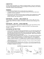
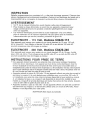
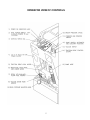
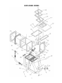
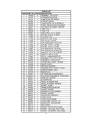
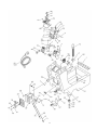
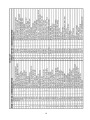
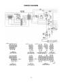
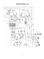
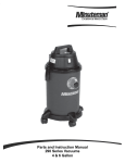
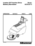
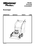
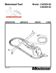
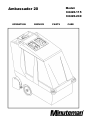
Model:
C8420-115
C8420-240
Ambassador 20
OPERATION
SERVICE
PARTS
CARE
This manual is furnished with each new Minuteman Ambassador 20. This provides the necessary
operating and preventative maintenance instructions. Operators must read and understand this
manual before operating or servicing this machine.
This machine was designed to give you excellent performance and efficiency. For best results and
minimal cost, please follow the general guidelines below:
• Operate the machine with reasonable care.
• Follow the manufacturer’s suggested maintenance instructions as provided in this manual.
• Use original Minuteman supplied parts.
TECHNICAL SPECIFICATIONS
Model
Model #
Voltage (AC)
Current
Sound Level
Brush Speed
Dimensions (LxWxH)
Weight (gross)
Ambassador 20
C8420-115 ; C8420-240
115V 60Hz ; 240V 50/60Hz
12 Amps (115V) ; 7 Amps (240V) (50Hz)
79 dBA @ operator’s ear ; 73.6 dBA @ 3 meters
1040 RPM
45 1/8” x 20 3/4” x 38 1-4” ; (114.6cm x 52.7cm x 97.2cm)
234 lbs ; (106 kg)
TABLE OF CONTENTS
IMPORTANT SAFETY INSTRUCTIONS.................................................................... 1
INSPECTION.............................................................................................................. 2
GROUNDING INSTRUCTIONS ................................................................................. 2
OPERATOR VIEW OF CONTROLS .......................................................................... 5
OPERATING INSTRUCTIONS................................................................................... 6
Accessory Attachments ........................................................................................... 6
EXPLODED VIEWS ................................................................................................... 7
WIRING DIAGRAM .................................................................................................. 15
TROUBLE SHOOTING GUIDE ................................................................................ 17
SOLUTION SYSTEM ............................................................................................ 17
SOLUTION RECOVERY ....................................................................................... 17
ELECTRICAL SYSTEM A.C.................................................................................. 18
Minuteman International Made Simple Commercial Limited Warranty..................... 19
COMMERCIAL USE ONLY
IMPORTANT SAFETY INSTRUCTIONS
When using an electrical appliance, basic precautions should always be followed, including the
following:
READ ALL INSTRUCTIONS BEFORE USING
WARNING: To reduce the risk of fire, electric shock, or injury:
•
Do not leave appliance when plugged in. Unplug from outlet when not in use and before
servicing.
WARNING
To reduce the risk of electrical shock – Do not expose to rain. Store indoors.
•
•
•
•
•
•
•
•
•
•
•
•
•
•
Do not allow to be used as a toy. Close attention is necessary when used near children.
Use only as described in this manual. Use only the manufacturer’s recommended
attachments.
Do not use with damaged cord or plug. If appliance is not working as it should, has been
dropped, damaged, left outdoors, or dropped into water, return it to an authorized service
center.
Do not pull or carry by cord, use cord as handle, close a door on a cord, or pull cord around
sharp edges or corners. Do not run appliance over cord. Keep cord away from heated
surfaces.
Do not unplug by pulling on the cord. To unplug grasp the plug, not the cord.
Do not handle the appliance with wet hands.
Do not put any object into the openings. Do not use if any opening is blocked; keep free of
dust, lint, hair, and anything that may reduce air flow.
Keep hair, loose clothing, fingers, and all parts of the body away from openings and moving
parts.
Do not pick up anything that is burning or smoking, such as cigarettes, matches, or hot
ashes.
Do not use without dust bag and/or filters in place.
Turn off all controls before unplugging.
Use extra care when cleaning on stairs.
Do not use to pick up flammable or combustible liquids such as gasoline or use in areas
where they may be present.
Connect to a properly grounded outlet only. See grounding instructions.
SAVE THESE INSTRUCTIONS
1
INSPECTION
Carefully unpack and inspect your machine for shipping damage. Each unit is tested and
thoroughly inspected before shipment, and any damage is the responsibility of the delivery
carrier who should be notified immediately.
WARNING
•
•
•
Read Instructions Manual before operating this piece of equipment.
To reduce the risk of fire use only commercially available floor cleaners and waxes
intended for machine application
Electrical motors and components can cause an explosion when operated near volatile
materials and vapors. Do not use this machine near flammable materials such as
solvents, thinners, fuels, grain dust, ect.
ELECTRICAL – 115 VOLT
Model C8420-115
This machine is designed to operate on a standard 15 amp. 120-Volt, 60hz, AC circuit.
Voltages below 105-Volt AC or above 125-Volts AC could cause serious damage to the
motor.
ELECTRICAL – 240 VOLT
Model C8420-240
This machine is designed to operate on a standard 16 amp. type L fused 230-Volt, 50 Hz,
AC circuit. Voltages below 200-Volt AC or above 250-Volts AC could cause serious
damage to the motor.
GROUNDING INSTRUCTIONS
•
•
•
This floor finishing machine should be grounded while in use to protect the operator from
electric shock. The machine is equipped with a three-conductor cord and three prong
grounding type attachment plug to fit the proper grounding type receptacle. The green
(green and yellow) conductor in the cord is the grounding wire. Never connect this wire
to anything other than the grounding blade.
Floor Finishing Machines Rated Less than 150-Volts – If the machine is provided with an
attachment plug, as shown in Sketch A, it is intended for use on a 120-Volt (normal)
circuit. If a properly grounded receptacle, as shown in Sketch A, is not available, an
adapter as shown in Sketch C, is available and be installed as shown in Sketch B if the
outlet box that houses the receptacle is grounded. Be sure to fasten the grounding tab
with the faceplate screw.
Floor Finishing Machines Rated More than 150-Volts – If the machine is provided with
attachment plug as shown in Sketch D, it is intended for use in nominal 240-Volt circuit.
No adapter is available for this plug.
2
3
4
OPERATOR VIEW OF CONTROLS
5
OPERATING INSTRUCTIONS
1.
Filling: Fill the solution tank with the desired amount of water and add liquid cleaning
solution to the proper dilution ratio. DO NOT USE powdered cleaning chemicals.
Powders are unlikely to dissolve thoroughly, resulting in clogging the inline solution
filter. This can reduce or stop water flow to the pump and spray jets.
2.
Connect power supply cord to grounded wall outlet, Item # 4
3.
Engage traction drive system, Item #5
4.
Turn on main power switch, Item #2
5.
Lower scrub head assembly, Item #6
6.
Turn on pump switch to automatic, Item #12
7.
Turn on vacuum, Item #13
8.
Set forward/reverse switch to forward, Item #11
9.
Engage traction drive control levers, Item #14
10.
Adjust forward speed #3
11.
Brush pressure can be adjusted + or – by knob, Item #9, and viewing gauge, Item
#10 in green zone
Accessory Attachments
1.
Turn master switch off
2.
Disconnect vac hose, see item #8, and attach vacuum hose from remote tool.
3.
Disconnect solution hose, see item #7, and install remote tool solution hose to the
quick disconnect. Turn the pump solution switch, item #13, to auxiliary.
4.
Turn on main power switch.
5.
Turn on switch #13 to activate vacuum motor.
6
EXPLODED VIEWS
7
8
9
10
11
12
13
14
WIRING DIAGRAM
15
WIRING DIAGRAM (cont’d)
16
TROUBLE SHOOTING GUIDE
Use this guide to pinpoint problem areas that may arise with the use of your Ambassador
20. CAUTION! Unplug supply cord before servicing machine components.
SOLUTION SYSTEM
I.
No water dispensed from spray jets
A. The hose connection at the pump for the spray tube may not be tight. Disconnect,
then reconnect the fitting, to ensure the fittings snap together securely.
B. The solution pump diaphragm may be damaged. Inspect by removing the
diaphragm from the pump and inspect the diaphragm for cracks. Replace if
required.
II.
Spray intermittent or streaked
A. Solution hoses may be clogged. Replaced kinked hoses if found.
B. The filter strainer in the solution tank may be clogged. Clean the strainer
thoroughly.
C. The spray jets may be clogged. Remove the end plug from the spray tube and flush
by turning the pump on. Remove the spray jets from the tube and clean as
required. Do not clean out the hole in the jet with a pin or wire. This may cause
permanent streaking.
SOLUTION RECOVERY
I. Solution recovery is reduced.
A. Vacuum filter maybe clogged. First check filter recovery tank. Clean if required.
B. Check the vacuum hoses for secure fit over the vacuum fittings. Tighten clamps
where used. Also check hoses for cracks, kinks or clogging.
C. Check the seals on the tank covers for damage. Replace if needed. Make sure
cover closes freely without restrictions.
D. Make sure the drain hose on the back of the tank is sealed.
E. Check the vacuum slot on the scrub head for clogging. Clean out the slot if
required.
F. Vacuum motor brushes could be worn. Inspect and replace. If motor has run
through two sets of brushes, replace the motor.
17
SOLUTION RECOVERY (cont’d)
II. Pump motor does not run.
A. Check pressure switch for short circuit. By-pass the pressure switch by connecting
the two black leads to the switch to one another, if the motor then runs, replace the
pressure switch.
III. Machine fails to run when handle switch is activated.
A. Speed control maybe shorted out.
B. Speed control potentiometer may be defective.
ELECTRICAL SYSTEM A.C.
I.
Vacuum motor does not start.
A. Inspect the micro switch lever inside the electrical enclosure to make sure it is
functioning properly. As the scrub head is lowered the lever should activate
the switch. Bend the switch lever to adjust function if required.
B. Check motor carbon brush.
C. Check plugs on power cord.
FOR ALL THE ABOVE MAKE SURE ALL THE ELECTRICAL CONNECTIONS ARE SECURE. MAKE
SURE THE CORD TO THE WALL OUTLET IS SECURE. MAKE SURE THE GFCI IS NOT TRIPPED IF THE
UNIT IS EQUIPPED WITH ONE (LOCATED ON POWER CORD).
18
Minuteman International Made Simple Commercial Limited Warranty
Minuteman International, Inc. warrants to the original purchaser/user that the product is free from defects in workmanship and
materials under normal use. Minuteman will, at its option, repair or replace without charge, parts that fail under normal use and
service when operated and maintained in accordance with the applicable operation and instruction manuals. All warranty claims
must be submitted through and approved by factory authorized repair stations.
This warranty does not apply to normal wear, or to items whose life is dependent on their use and care, such as belts, cords,
switches, hoses, rubber parts, electrical motor components or adjustments. Parts not manufactured by Minuteman are covered by
and subject to the warranties and/or guarantees of their manufacturers. Please contact Minuteman for procedures in warranty
claims against these manufacturers.
Special warning to purchaser -- Use of replacement filters and/or prefilters not manufactured by Minuteman or its designated
licensees, will void all warranties expressed or implied. A potential health hazard exits without original equipment replacement.
All warranted items become the sole property of Minuteman or its original manufacturer, whichever the case may be.
Minuteman disclaims any implied warranty, including the warranty of merchantability and the warranty of fitness for a particular
purpose. Minuteman assumes no responsibility for any special, incidental or consequential damages.
This limited warranty is applicable only in the U.S.A. and Canada, and is extended only to the original user/purchaser of this
product. Customers outside the U.S.A. and Canada should contact their local distributor for export warranty policies. Minuteman is
not responsible for costs or repairs performed by persons other than those specifically authorized by Minuteman. This warranty
does not apply to damage from transportation, alterations by unauthorized persons, misuse or abuse of the equipment, use of noncompatible chemicals, or damage to property, or loss of income due to malfunctions of the product.
If a difficulty develops with this machine, you should contact the dealer from whom it was purchased.
This warranty gives you specific legal rights, and you may have other rights which vary from state to state. Some states do not allow
the exclusion or limitation of special, incidental or consequential damages, or limitations on how long an implied warranty lasts, so
the above exclusions and limitations may not apply to you.
Cord Electric Group………..Three years parts, two years labor, ninety days travel
(Not to exceed two hours)
Exceptions………. Port-A-Scrub, one year parts, six months labor
MPV 13, one year parts
MPV 14 and 18, two years parts, one year labor
RapidAir blower, one year parts, one year labor
Explosion-Proof Vacuum, one year parts, one year labor
Pneumatic Vacuums, three years parts, one year labor
Battery Operated Group….. Three years parts, two years labor, ninety days travel
(Not to exceed two hours)
Exceptions……..…Sweepers, one year parts, one year labor, ninety days travel
(Not to exceed two hours)
Internal Combustion Group….One year parts, one year labor, ninety day travel
(Not to exceed two hours)
Replacement Parts……………..Ninety days
Batteries………………………….0-3 months replacement, 4-12 months pro-rate
Polypropylene Plastic Tanks…Ten years, no additional labor
A Member of the Hako Group of Companies
111 South Rohlwing Road · Addison, Illinois 60101 USA
Phone 630- 627-6900 · Fax 630- 627-1130
E-Mail, www.minutemanintl.com
P.N. 988403
Rev A 07/06
19