1
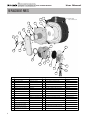
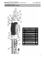
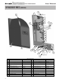
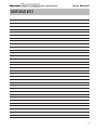
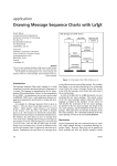
User
Manual
GAS-FIRED
MH18082
GAS-FIRED HEATER
User Manual
TABLE OF CONTENTS
Product and Safety Information . . . . . . . . . . . . . . . . . . . . . . . . . . . . . . . . . . . . . . . . . . . . . 2,3
Service and Maintenance
Munchkin Contender Operation
Primary Water
Section I – Combustion Air – Prevention of Contamination. . . . . . . . . . . . . . . . . . . . . . . . 4
Potential Contaminating Products
Areas likely to find these Products
Section II – Maintenance Schedule . . . . . . . . . . . . . . . . . . . . . . . . . . . . . . . . . . . . . . . . . . 4,5
Service Technician
Owner Maintenance
Section III – Maintenance Procedures . . . . . . . . . . . . . . . . . . . . . . . . . . . . . . . . . . . . . . . . 5-7
Daily Maintenance
Monthly Maintenance
6 Month Maintenance
Section IV – Start-Up Procedure . . . . . . . . . . . . . . . . . . . . . . . . . . . . . . . . . . . . . . . . . . . . . . 8
Replacement Parts . . . . . . . . . . . . . . . . . . . . . . . . . . . . . . . . . . . . . . . . . . . . . . . . . . . . . . . . 9-11
1
User Manual
GAS-FIRED HEATER
PRODUCT AND SAFETY INFORMATION
SPECIAL ATTENTION BOXES
The following defined terms are used throughout this manual to bring attention to the presence of
hazards of various risk levels or to important information concerning the product.
DEFINITIONS
DANGER
CAUTION
DANGER indicates an imminently hazardous
situation which, if not avoided, will result in
death or serious injury.
CAUTION Indicates a potentially hazardous
situation which, if not avoided, may result in
minor or moderate injury.
WARNING
CAUTION
WARNING indicates a potentially hazardous
situation which, if not avoided, could result in
death or serious injury.
CAUTION used without the safety alert symbol
indicates a potentially hazardous situation which,
if not avoided, may result in property damage.
WARNING
If the information in this manual is not followed exactly, a fire or explosion may result causing property damage, personal injury or loss of life.
Do not store or use gasoline or other flammable vapors and
liquids in the vicinity of this or any other appliance.
WHAT TO DO IF YOU SMELL GAS
• Do not try to light any appliance.
• Do not touch any electrical switch: do not use any phone in
your building.
• Immediately call your gas supplier from a neighbor's phone.
Follow the gas supplier's instructions.
• If you cannot reach your gas supplier, call the fire department.
Installation and service must be performed by a qualified
installer, service agency or the gas supplier.
NOTICE
Heat Transfer Products, Inc., reserves the right to make product changes or updates without notice
and will not be held liable for typographical errors in literature.
2
User Manual
GAS-FIRED HEATER
PRODUCT AND SAFETY INFORMATION (CONT’D)
PRIMARY WATER
WARNING
User — Have this heater serviced/inspected by
a qualified service technician annually.
•
If you have an old system with cast iron
radiators, thoroughly flush the system
(without heater connected) to remove
sediment. The high-efficiency heat exchanger
can be damaged by build-up or corrosion
due to sediment.
•
Do not use petroleum-based cleaning or
sealing compounds in heater system.
Gaskets and seals in the system may be
damaged. This can result in substantial
property damage.
•
Do not use “homemade cures” or “boiler
patent medicines.” Substantial property
damage, damage to boiler, and/or serious
personal injury may result.
•
Continual fresh make-up water will reduce
heater life. Mineral buildup in heat exchanger
reduces heat transfer, overheats the stainless
steel heat exchanger, and causes failure.
Addition of oxygen carried in by make-up
water can cause internal corrosion in system
components. Leaks in heater or piping must
be repaired at once to prevent make-up
water.
WARNING
Failure to adhere to the guidelines on this page
can result in severe personal injury, death or
substantial property damage.
WARNING
WHAT TO DO IF YOU SMELL GAS
• Do not try to light any appliance.
• Do not touch any electric switch; do not use
any phone in your building.
• Immediately call your gas supplier from a
neighbor's phone. Follow the gas suppliers'
instructions.
• If you cannot reach your gas supplier, call the
fire department.
HEATER OPERATION
•
Do not block flow of combustion or
ventilation air to the heater.
•
Should overheating occur or gas supply fail
to shut off, do not turn off or disconnect
electrical supply to circulator. Instead, shut off
the gas supply at a location external to the
appliance.
•
3
Do not use this heater if any part has been
under water. Immediately call a qualified
service technician to inspect the heater and
to replace any part of the control system and
any gas control that has been under water.
FREEZE PROTECTION FLUIDS
CAUTION
NEVER use automotive or standard glycol
antifreeze, even ethylene glycol made for
hydronic systems. Use only inhibited propylene
glycol solutions, which are specifically
formulated for hydronic systems. Ethylene
glycol is toxic and can attack gaskets and seals
used in hydronic systems.
GAS-FIRED HEATER
User Manual
SECTION I – COMBUSTION AIR – PREVENTION OF CONTAMINATION
AREAS LIKELY TO FIND THESE PRODUCTS
WARNING
Products to avoid
If the Munchkin Contender combustion air inlet
is located in any area likely to cause or contain
contamination, or if products, which would
contaminate the air cannot be removed, the
combustion air must be re -piped and
terminated to another location. Contaminated
combustion air will damage the unit and its
burner system, resulting in possible severe
personal injury, death or substantial property
damage.
Spray cans containing fluorocarbons
Permanent wave solutions
Chlorinated waxes/cleaners
Chlorine-based swimming pool chemicals
Calcium chloride used for thawing
Sodium chloride used for water softening
Refrigerant leaks
Paint or varnish removers
Hydrochloric acid/muriatic acid
Cements and glues
Antistatic fabric softeners used in clothes dryers
Chlorine-type bleaches, detergents, and cleaning
solvents found in household laundry rooms
Adhesives used to fasten building products and
other similar products
WARNING
Do not operate a Munchkin Contender unit if its
combustion air inlet or the unit is located in or
near a laundry room or pool facility. These areas
will always contain hazardous contaminates.
Pool and laundry products and common
household and hobby products often contain
fluorine or chlorine compounds. When these
chemicals pass through the burner and vent
system, they can form strong acids. These acids
can create corrosion of the heat exchanger,
burner components and vent system, causing
serious damage and presenting a possible
threat of flue gas spillage or water leakage into
the surrounding area.
Areas likely to have contaminants
Dry cleaning/laundry areas and establishments
Swimming pools
Metal fabrication plants
Beauty shops
Refrigeration repair shops
Photo processing plants
Auto body shops
Plastic manufacturing plants
Furniture refinishing areas and establishments
New building construction
Remodeling areas
Garages and workshops
SECTION II – MAINTENANCE SCHEDULE
SERVICE TECHNICIAN
On an annual basis the following maintenance
should be performed by a qualified service technician:
•
Check heater water pressure, piping and
expansion tank.
•
Check control settings.
•
Check ignition electrode (use Scotch Brite Pad
and sand off any white oxide; clean and
reposition).
•
Check ignition wiring and ground wiring.
•
Check all control wiring and connections.
•
Check burner flame pattern (stable and
uniform) and flame.
General
•
Attend to any reported problems.
•
Inspect the interior of the heater jacket area;
clean and vacuum if necessary.
•
Clean the condensate trap and fill with fresh
water.
•
Check for leaks: water, gas, flue and
condensate.
•
Verify flue vent piping and air inlet piping are
in good condition and sealed tight.
Additional items if combustion or
performance is poor:
•
Clean heat exchanger and flue ways.
•
Remove burner assembly and clean burner
4
GAS-FIRED HEATER
User Manual
SECTION II – MAINTENANCE SCHEDULE (CONT’D)
head using compressed air only.
Once the maintenance items are completed,
review the service with the owner.
OWNER MAINTENANCE
Periodically:
•
Check the area around the unit.
•
Check and remove any blockage from the
combustion air inlet and ventilation openings.
•
Check the temperature/pressure gauge
Monthly:
•
Check vent piping.
•
Check combustion air inlet piping.
•
Check the pressure relief valve.
•
Check the condensate drain system.
Every 6 months:
•
Check heater piping and gas supply piping
for corrosion or potential signs of leakage.
WARNING
Follow the maintenance procedures given
throughout this manual. Failure to perform the
service and maintenance or follow the
directions in this manual could result in damage
to the Munchkin Contender or in system
components, resulting in severe personal injury,
death or substantial property damage.
SECTION III – MAINTENANCE PROCEDURES
WARNING
The Munchkin Contender must be inspected
and serviced annually, preferably at the start of
the heating season, by a qualified service
technician. In addition, the maintenance and
care of the heater as outlined on page 3 and
further explained on pages 4 through 6 must be
performed to assure maximum efficiency and
reliability of the unit. Failure to service and
maintain the Munchkin Contender and the
system components could result in equipment
failure, causing possible severe personal injury,
death or substantial property damage.
NOTICE
The following information provides detailed
instruction for completing the maintenance
items outlined in the maintenance schedule in
Section II. In addition to this maintenance, the
Munchkin Contender should be serviced at the
beginning of the heating season by a qualified
service technician.
DAILY MAINTENANCE
Check the surrounding area
5
WARNING
To prevent potential of severe personal injury,
death or substantial property damage, eliminate
all the materials listed in Section I from the area
surrounding the unit and from the vicinity of the
combustion air inlet. If contaminates are found:
Remove products immediately from the area. If
they have been there for an extended period,
call a qualified service technician to inspect the
unit for possible damage from acid corrosion.
If products cannot be removed, immediately call
a qualified service technician to re-pipe the
combustion air inlet piping and locate the
combustion air intake away from the
contaminated areas.
1. Combustible / flammable materials - Do not
store combustible materials, gasoline or
other flammable vapors or liquids near the
unit. Remove immediately if found.
2. Air contaminates - Products containing
chlorine or fluorine, if allowed to contaminate
the combustion air, will cause acidic
condensate within the unit. This will cause
significant damage to the unit. Read the list of
potential materials listed in Section I of this
manual. If any of these products are in the
room where the boiler is located, they must
GAS-FIRED HEATER
User Manual
SECTION III – MAINTENANCE PROCEDURES (CONT’D)
be removed immediately or the combustion
air intake must be relocated to another area.
Check Combustion Air Inlets
Verify that the unit’s vent termination and
combustion air intake are clean and free of
obstructions. Remove any debris on the air
intake or flue exhaust openings. If removing
the debris does not allow the unit to operate
correctly, contact your qualified service
technician to inspect the unit and the vent /
combustion air system.
Check Temperature display and Pressure
Gauge
1. Ensure the pressure reading on the pressure
gauge does not exceed 25 psig. Higher
pressure readings may indicate a problem
with the expansion tank.
2. Ensure the temperature on the LED display
panel does not exceed 180ºF. Higher
temperature readings may indicate a
problem with the operating thermostat
controls.
3. Contact a qualified service technician if
problem persists.
MONTHLY MAINTENANCE
Check Vent Piping
1. Visually inspect the flue gas vent piping for
any signs of blockage, leakage or
deterioration of the piping. Notify a qualified
service technician immediately if any
problems are found.
WARNING
Failure to inspect the venting system as noted
and have it repaired by a qualified service
technician can result in the vent system failure,
causing severe personal injury or death.
Check Intake Air Vent Piping
Check Pressure Relief Valve
1. Visually inspect the primary pressure relief
valve and the relief valve discharge pipe for
signs of weeping or leakage.
2. If the pressure relief valve often weeps, the
expansion tank may not be operating
properly. Immediately contact a qualified
service technician to inspect the unit and
system.
Check Vent Condensate Drain System
1. While the unit is running, check the discharge
end of the condensate drain tubing. Ensure
no flue gas is leaking from the condensate
drain tubing or tee connection by holding
your fingers near the opening.
2. If you notice flue gas leaking from the
opening, this indicates a dry condensate
drain trap. Fill the condensate trap assembly.
Contact a qualified service technician to
inspect the unit and condensate line and refill
the condensate trap if problem persists
regularly.
3. The Service Technician must ensure the
condensate drain line is not blocked by
pouring water through the plug port on the
condensate drain assembly. The water
should flow out of the end of the drain line. If
water does not appear at the end of the drain
line, the qualified service technician must
clean the condensate line.
4. To fill the condensate drain assembly, remove
the cup from the condensate assembly.
Slowly pour water into the cup assembly
until water appears at the end of the drain
line. Stop filling and replace cup.
WARNING
You must make sure the condensate cup is
securely fastened before restarting heater. Do a
final check to assure proper flow.
1. Visually inspect the intake air vent piping for
any signs of blockage. Inspect the entire
length of the intake air vent piping to ensure
piping is intact and all joints are properly
sealed.
2. Notify a qualified service technician if any
problems are found.
6
GAS-FIRED HEATER
User Manual
SECTION III – MAINTENANCE PROCEDURES (CONT’D)
6-MONTH MAINTENANCE
Check primary and gas piping
1. Remove the heater cover and perform a gas
leak inspection following Operating
Instructions in Section IV. If gas odor or leak
is detected, immediately shut down the unit
following procedures on page 8. Call a
qualified service technician.
2. Visually inspect for leaks around the internal
heater water connections and around the
heat exchanger. Visually inspect the external
system piping, circulators, and system
components and fittings. Immediately call a
qualified service technician to repair any
leaks.
WARNING
Have leaks fixed at once by a qualified service
technician. Failure to comply could result in
severe personal injury, death or substantial
property damage.
Operate Pressure Relief Valve
1. Before proceeding, verify that the relief valve
outlet has been piped to a safe place of
discharge, avoiding any possibility of
scalding from hot water.
WARNING
To avoid water damage or scalding due to valve
operation, a discharge line must be connected
to the relief valve outlet and directed to a safe
place of disposal. This discharge line must be
installed by a qualified service technician or
heating/plumbing installer in accordance with
the Munchkin Contender installation manual.
The discharge line must be terminated so as to
eliminate possibility of severe burns or property
damage should the valve discharges.
2. Read the temperature and pressure gauge to
ensure the system is pressurized. Min. is 10
PSI and Max is 25 PSI. Lift the relief valve top
lever slightly, allowing water to relieve
through the valve and discharge piping.
3. If water flows freely, release the lever and
allow the valve to seat. Watch the end of the
relief valve discharge pipe to ensure that the
7
valve does not weep after the line has had
time to drain. If the valve weeps, lift the lever
again to attempt to clean the valve seat. If the
valve does not properly seat and continues to
weep afterwards, contact a qualified service
technician to inspect the valve and system.
4. If the water does not flow from the valve
when you lift the lever completely, the valve
or discharge line may be blocked.
Immediately shut the unit down per
instructions on page 8 and call a qualified
service technician to inspect the valve and
system.
GAS-FIRED HEATER
User Manual
SECTION IV – OPERATIONS INSTRUCTIONS
FOR YOUR SAFETY READ BEFORE OPERATING
WARNING: If you do not follow these instructions exactly, a fire or explosion may
result, causing property damage, personal injury or loss of life.
A. This appliance does not have a pilot. It is equipped
with an ignition device which automatically lights the
burner. Do not try to light the burner by hand.
B. BEFORE OPERATING smell all around the appliance
area for gas. Be sure to smell next to the floor
because some gas is heavier than air and will settle on
the floor.
WHAT TO DO IF YOU SMELL GAS
• Do not try to light any appliance
• Do not touch any electric switch;
do not use any phone in your building
• If you cannot reach your gas supplier, call the fire
department.
C. Use only your hand to turn the gas control knob.
Never use tools. If the handle will not turn by hand,
don't try to repair it, call a qualified service technician.
Force or attempted repair may result in a fire or
explosion.
D. Do not use this appliance if any part has been under
water. Immediately call a qualified service technician
to inspect the appliance and to replace any part of the
control system and any gas control which has been
under water.
• Immediately call your gas supplier from a neighbor's
phone. Follow the gas suppliers' instructions.
OPERATING INSTRUCTIONS
1. STOP! Read the safety information above.
5. Remove front cover.
2. Set the thermostat to lowest setting.
6. Turn gas shutoff valve clockwise to "off". Handle will
be vertical, do not force.
3. Turn off all electric power to the appliance.
4. This appliance is equipped with an ignition device
which automatically lights the burner. Do not try to
light the burner by hand.
GAS SHUT OFF VALVE
7. Wait five (5) minutes to clear out any gas. If you then
smell gas, STOP! Follow "B" in the safety
information above on this label. If you don't smell
gas, go to next step.
8. Turn gas shutoff valve counterclockwise to "on".
Handle will be horizontal.
9. Install Front Cover.
10. Turn on all electric power to appliance.
11. Set thermostat to desired setting.
12. If the appliance will not operate, follow the
instructions "To Turn Off Gas To Appliance" and call
your service technician or gas supplier.
GAS
VALVE
TO TURN OFF GAS TO APPLIANCE
1. Set the thermostat to lowest setting.
2. Turn off all electric power to the appliance if service is
to be performed.
3. Remove Front Cover.
4. Turn gas shutoff valve clockwise to "off". Handle will
be vertical. Do not force.
5. Install Front Cover.
8
User Manual
GAS-FIRED HEATER
REPLACEMENT PARTS
1
HEATER LIMIT
FUSE CONNECTION
2
5
4
3
6
8
7
9
11
10
16
13
12
21
10
14
18
17
15
19
22
20
23
24
REPLACEMENT PARTS
Item #
1
Description
Composite Module
Part #
7500P-010 (MC50)
Item #
13
Description
Screws M4x8 (Probe/Electrode)
7500P-012 (MC80)
14
Gasket (Air Channel to Combustion Blower) 7500P-075
7500P-014 (MC99/MC120)
15
Combustion Blower (w/Screws)
7500P-031
7250P-161
16
Screws M4x7 (Combustion Blower)
7250P-254
2
Ceramic Target Wall
3
Burner Door Ceramic Refractory 7500P-076
17
Gas Valve Adapter Plate (w/Screws)
7250P-644
4
Burner Door (w/Nuts)
7500P-078
18
Screws M5x12 (Gas Valve Adapter Plate)
7500P-105
5
Nuts - M6 (Burner Door)
7500P-067
19
Gas Valve Swirl Plate
6
NIT Burner
7500P-015 (MC50)
7500P-017 (MC99/MC120)
7
Gasket (Burner)
8
Air/Gas Channel (w/Torx Screws) 7500P-079
9
Torx Screws (Air/Gas Channel)
Gasket (Flame Rec./Spark
Electrode)
Flame Rectification Probe
(w/Gasket, Screws)
Spark Electrode (w/Gasket,
Screws)
10
11
12
7500P-091(MC50)
7500P-092 (MC80)
7500P-016 (MC80)
9
Part #
7250P-069
7500P-093 (MC99/MC120)
20
Gas Valve (w/Swirl Plate, Screws)
7500P-074
7250P-448 (MC50)
7250P-449 (MC80)
7000P-862 (MC99/MC120)
7500P-068
21
Screws M4x0.7 (Gas Valve)
7500P-099
7250P-005
22
O-Ring (Gas Valve Piping Assy)
7500P-094
7500P-039
23
Gas Valve Piping Assembly (w/O-ring,
Screws)
7500P-095
7500P-040
24
Screws M4x0.7 (Gas Valve Piping Assy)
7500P-099
User Manual
GAS-FIRED HEATER
REPLACEMENT PARTS (CONTINUED)
1
2
6
8
7
3
9
4
10
5
11
12
REPLACEMENT PARTS
Description
Item #
1
2
3
4
5
13
14
16
15
17
18
Concentric Flue Outlet (w/Gasket)
Gasket (Concentric Flue Outlet)
PVC Pipe (2" Sch. 40 - 12" Long)
Flue Adapter
Part #
7500P-025
7500P-008
7500P-097
7500P-007
7500P-002
6
Flue ECO
O-Ring (S.S. Barbed Fitting)
7
S.S. Barbed Fitting
7250P-154
8
9
10
Water Pressure Switch
Clear Tubing 3/16 ID x 5/16 OD
Water Pressure Switch Adapter
7000P-805
7500P-003
11
O-Ring (Water Pressure Switch)
7500P-100
12
13
Water Pressure Switch Clip
Supply/Return Manifold Clip
7500P-077
7500P-080
14
15
16
O-Ring (Supply/Return Manifold)
Thermistor
High Limit Sensor
7500P-026
7250P-059
7500P-033
17
Relief Valve
7250P-080
18
Supply Manifold Assembly (w/O-Ring, Relief
7500P-029
Valve, Temperature/Pressure Gauge)
19
20
Return Manifold Assembly (w/O-Ring)
Temperature/Pressure Gauge
7250P-152
7250P-096
7500P-030
7500P-098
19
20
10
User Manual
GAS-FIRED HEATER
REPLACEMENT PARTS (CONTINUED)
1
2
21
3
5
6
9
4
10
7
8
11
12
11
13
14
16
15
17
20
18
19
REPLACEMENT PARTS
Part #
Item # Description
Item # Description
11
Part #
1
Cover Filler Plate(w/Screws)
7500P-044 (MC50/MC80)
12
Condensate Hose (clear)
7500P-057
2
Blocked Vent Pressure Switch
7500P-032 (MC99/MC120)
13
Screws 8-32x3/8 (Filler/Gas Inlet Plate) 7500P-047
7250P-150
14
3
Screws 8-32x3/8 (Blocked Vent Pressure
Switch)
Supply/Return Filler Plate (w/Screws)
7500P-047
4
Control Board (w/Screws)
7250P-317
15
Lip Style Grommet - 1"
5
5 Pin Wiring Harness (location)
7500P-050
7500P-055
16
Lip Style Grommet - 1/2"
7500P-049
6
9 Pin Wiring Harness (location)
7500P-054
17
Gas Inlet Plate
7500P-043
7
Low Voltage Wiring Harness (location)
7500P-053
18
Condensate Switch
7500P-041
8
Screws # 6 x 1/2 - Control Board
7250P-480
19
Condensate Cup
7500P-090
9
Clamp -Module to Bracket (w/Screws)
7500P-073
20
Control Board Display
7500P-058
10
Screws M4x6 (Clamp)
7500P-069
21
Contender Cover
7500P-027 (MC50/MC80)
11
Spring Clamp - Condensate Hose
7250P-302
7500P-022 (MC50/MC80)
7500P-023 (MC99/MC120)
7500P-028 (MC99/MC120)
GAS-FIRED HEATER
User Manual
MAINTENANCE NOTES
12
GAS-FIRED HEATER
MAINTENANCE NOTES
13
User Manual
GAS-FIRED HEATER
User Manual
MAINTENANCE NOTES
14
© 2006 Heat Transfer Products, Inc.
LP-180 REV. 10/16/06