1
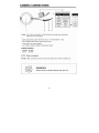
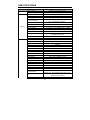
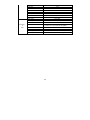
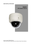
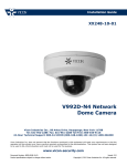
Installation and Operation Guide
XX236-10-01
V661V-312IR Vandal-Proof
IR Analog Camera Dome
Vicon Industries Inc., 89 Arkay Drive, Hauppauge, New York 11788
Tel: 631-952-2288 Fax: 631-951-2288 Toll Free: 800-645-9116
24-Hour Technical Support: 800-34-VICON (800-348-4266) UK: 44/(0) 1489-566300
Vicon Industries Inc. does not warrant that the functions contained in this equipment will meet your requirements or that the
operation will be entirely error free or perform precisely as described in the documentation. This system has not been designed
to be used in life-critical situations and must not be used for this purpose.
www.vicon-security.com
Document Number: 8009-8236-10-01
Product specifications subject to change without notice.
Issued: 1011
Copyright © 2011 Vicon Industries Inc. All rights reserved.
WARNING
TO REDUCE THE RISK OF FIRE OR ELECTRIC SHOCK, DO NOT EXPOSE THIS PRODUCT TO RAIN OR
MOISTURE. DO NOT INSERT ANY METALLIC OBJECTS THROUGH THE VENTILATION GRILLS OR
OTHER OPENINGS ON THE EQUIPMENT.
CAUTION:
CAUTION
CAUTION: TO REDUCE THE RISK OF ELECTRIC SHOCK,
DO NOT REMOVE COVER(OR BACK).
NO USER-SERVICEABLE PARTS INSIDE.
REFER SERVICING TO QUALIFIED SERVICE PERSONNEL.
EXPLANATION OF GRAPHICAL SYMBOLS
The lightning flash with arrowhead symbol, within an equilateral triangle, is
intended to alert the user to the presence of uninsulated "dangerous voltage"
within the product's enclosure that may be of sufficient magnitude to constitute a
risk of electric shock to persons.
The exclamation point within an equilateral triangle is intended to alert the user to
the presence of important operating and maintenance (servicing) instructions in the
literature accompanying the product.
PRECAUTIONS
Safety -----------------------------------------
Cleaning --------------------------------------
Should any liquid or solid object fall into the cabinet,
unplug the unit and have it checked by the qualified
personnel before operating it any further.
Clean the unit with a slightly damp soft cloth.
Use a mild household detergent. Never use
strong solvents such as thinner or benzine as
they might damage the finish of the unit.
Unplug the unit from the wall oulet if it is not going to
be used for several days or more. To disconnect the
cord, pull it out by the plug. Never pull the cord itself.
Retain the original carton and packing
materials for safe transport of this unit in the
future.
Allow adequate air circulation to prevent internal heat
build-up. Do not place the unit on surfaces (rugs,
blankets, etc.) or near materials(curtains, draperies)
that may block the ventilation holes.
Height and vertical linearity controls located at the
rear panel are for special adjustments by qualified
personnel only.
2
3
IMPORTANT SAFETY INSTRUCTIONS
1.
Read these instructions.
2.
Keep these instructions.
3.
Heed all warnings.
4.
Follow all instructions.
5.
Do not use this apparatus near water.
6.
Clean only with dry cloth.
7.
Do not block any ventilation openings. Install in accordance with the manufacturer’s
instructions.
8.
Do not install near any heat sources such as radiators, heat registers, stoves, or
other apparatus (including amplifiers) that produce heat.
9.
Do not defeat the safety purpose of the polarized or grounding-type plug.
A polarized plug has two blades with one wider than the other. A grounding type
plug has two blades and a third grounding prong. The wide blade or the third prong
are provided for your safety. If the provided plug does not fit into your outlet, consult
an electrician for replacement of the obsolete outlet.
10. Protect the power cord from being walked on or pinched particularly at plugs,
convenience receptacles, and the point where they exit from the apparatus.
11. Only use attachments/accessories specified by the manufacturer.
12. Use only with the cart, stand, tripod, bracket, or table specified by
the manufacturer, or sold with the apparatus. When a cart is used,
use caution when moving the cart/apparatus combination to avoid
injury from tip-over.
13. Unplug this apparatus during lightning storms or when unused for
long periods of time.
14. Refer all servicing to qualified service personnel. Servicing is required when the
apparatus has been damaged in any way, such as power-supply cord or plug is
damaged, liquid has been moisture, does not operate normally,
or has been dropped.
15. CAUTION – THESE SERVICING INSTRUCTIONS ARE FOR USE BY QUALIFIED
SERVICE PERSONNEL ONLY. TO REDUCE THE RISK OF ELECTRIC SHOCK
DO NOT PERFORM ANY SERVICING OTHER THAN THAT CONTAINED IN THE
OPERATING INSTRUCTIONS UNLESS YOU QRE QUALIFIED TO DO SO.
16. Use satisfy clause 2.5 of IEC60950-1/UL60950-1 or Certified/Listed Class 2 po
wer source only.
4
INTRODUCTION
The camera provides high-quality images using Sony CCD technology especially
designed for closed-circuit television (CCTV) and security surveillance
applications.
Features:
High resolution and high performance 1/3" Sony® Super HAD™ II Technology
Excellent picture quality
600 lines(Color) of resolution
30EA, 850nm IR LED
0.14 Lux(Color), 0.03 Lux(B/W) @ F1.2, 30IRE Sensitivity
Auto electronic shutter [1/60(1/50) ~ 1/100,000] and manual electronic shutter modes
OSD (On Screen Display)
Auto and manual white balance modes
BLC (Back Light Compensation)
Day & Night (Auto / DAY / NIGHT / EXT)
Privacy Zone 6 Point, Polygonal Mosaic
AGC (Auto Gain Control)
Sense-up (x2 ~ x256)
MIRROR (NORMAL / MIRROR / VERTICAL / ROTATE)
VIDEO OUT ( BNC,UTP(option) )
Motion Detection(240 cells can be selected or deselected)
SLC (Side Light Compensation)
HDR (WDR)
DIS (Digital Image Stabilization)
DPC (Dead Pixel Cancellation)
RS485 Control (pelco D)
Operates in AC24V ± 10% / DC12V ± 10%
Use Certified / Listed Class 2 power source only
Camera Mount : camera mount directly to the wall or ceiling
Test Monitor Output
IMPORTANT: The user of this camera is responsible for
checking and complying with local, state, and federal laws
and statutes concerning the recording and monitoring of
audio signals.
5
6
7
8
9
THE DEFINITION TERMS
White Balance
Compensates for deviations in the white color caused by changes in the color
temperature of the light source so that the colors are reproduced correctly.
Exposure
Adjusts the images to the optimum brightness.
SHT (Electronic Shutter)
Controls the integration time (exposure) of the photodiode array and reduces blooming,
overexposure, and smear when capturing moving objects.
Flicker (FLC)
Avoids image flicker when there is a discrepancy between current and frequency
AGC (Automatic Gain Control)
Automatically adjusts (boosts) the video signal to the required level to produce a quality
image in low light situations
Sens-Up (Slow Shutter)
Allows the video sensor of a camera to control sensitivity as it automatically detects the
light level in dark environments to maintain a clear picture.
Back Light Compensation (BLC)
Compensates for the brightness of the subjects with a large amount of background light
that would make it practically impossible to see any details of the subjects. Adjusts the
iris so that a distinctive subject and the background are delivered at the same time.
Wide Dynamic Range (WDR)
Extends the action of BLC. When both high-brightness subjects and low-brightness
subjects are in the same scene, overexposure in the high-brightness subjects or loss of
dark detail in the low-brightness subjects may occur. WDR combines the two images to
eliminate over exposure and loss of detail.
ECLIPSE
When a high-brightness subject is shot, it may not be brought into focus because of the
large surface area over which the high-brightness pixels are spread. In cases like this,
the high-brightness subject can be brought into focus by using this function.
SLC (Side Light Compensation)
Adjusts the brightness of the image in the corners of the screen.
Mask
Hides one or more areas that the user does not want to be displayed on screen. Masks
can be set with their own display area, color, darkness and mosaic processing.
Detection
Detects motion within the scene using one of the available methods. Some methods
trigger the Alarm output.
Sharpness
Reducing this parameter adjusts the noise level to smooth out the "noise" caused by the
compression.
Caution should be taken not to reduce it too much, which may result in a blurred
image.
10
Resolution
Controls the display of fine details. The higher the resolution, the higher level of details
can be seen.
3D -DNR (Digital Noise Reduction)
Adjusts the illuminance noise level in low light situations by reducing image noise in
order to improve the image.3D-NR is time-based.
Nega
Reverses the color signals for the Chroma signal so the image looks like a “negative.”
D-ZOOM
Adjusts the camera position and zooms in on a section of the overall full image. The
pixels in this area are then enlarged so the image is the same size as the original, giving
the appearance of being zoomed in. Widens the intervals between the pixels in the
original signal according to the magnification, and then fills these intervals with
interpolation signals. This includes electronic pan, tilt and zoom.
RS485
Connects a camera control unit, such as a keyboard, by using “Pelco D” Protocol.
LLC (Line Lock Control)
In the line lock mode, the AC power supply and vertical sync signal of the cameras are
synchronized to prevent picture roll when switching between cameras in multiple
camera installations.
DPC (Dead Pixel Cancellation)
Automatically remove defective pixels from an image and “fill in” the image to maintain
the image quality. White pixels whose frequency of occurrence varies in proportion to
the temperature are sometimes observed when the devices are used under the
influence of external factors or especially high temperatures. The white pixel detection
and compensation function can automatically detect and compensate up to 64 white
pixels with the highest detection level in sequence so as to maintain the image quality.
Day/Night
Allows the camera to be effective even in the lowest of light conditions while still
showing clear color pictures during daylight hours. Day/Night cameras automatically
change from color images to black and white when the light levels drop below a certain
level.
DIS (Digital Image Stabilization)
Adjusts a shaky screen due to any vibration.
11
CAMERA OPERATION WITH O.S.D
<MAIN MENU>
EXPOSURE SET
COLOR SET
DAY & NIGHT SET
SPECIAL SET
MOTION DET.
PRIVACY SET
SETUP
EXIT
<DAY/NIGHT>
D/N MODE
C-SUP
A-SUP
RETURN
<PRIVACY>
MASK1
MASK2
MASK3
MASK4
MASK5
MASK6
RETURN
<EXPOSURE>
LENS
E. SHUTTER
BLC
HDR
AGC
SENSE UP
RETURN
< COLOR >
WB MODE
R-Y GAIN
B-Y GAIN
RETURN
<SPECIAL>
< MOTION DET.>
MOTION
SET WINDOW
ALL SET
ALL CLEAR
SENSITI
SHOW INDI
DELAY OUT
RETURN
MIRROR
SHARPNESS
GAMMA
FREEZE NEGA
3D DNR
D_ZOOM
SLC
ECLIPSE
DIS
RETURN
<SETUP>
SYNC
CAMERA ID
TITLE
DPC
MONITOR
BAUDRATE
RETURN
12
<EXIT>
EXIT
SAVE & EXIT
FACTORY SET
RETURN
OSD MAIN SCREEN
ALL operation is via the tact switch
[CENTER]
Turn OSD menu ON or to go into Sub Menu
[UP] / [DOWN]
UP or DOWN of Cursor
[LEFT] / [RIGHT] Change setting
<EXPOSURE SET>
Press the [ENTER] button to access the “EXPOSURE SET” mode.
1) LENS : Select the type of lens.
MANUAL : Select when fixed lens is used
Sub Menu - MANUAL Level adjustment
(Adjust brightness of fixed lens)
DC : Select when DC Varifocal lens is used
Sub Menu -DC Level adjustment
(Adjust brightness of varifocal lens)
2) E. SHUTTER : Shutter setting
Able to set from 256 to 1/100000 (Shutter speed adjustment)
Change FLK MODE(Select when using flicker mode)
3) BLC : BLC Setting
Select BLC ON/OFF(Backlight compensation function)
Sub Menu -Set BLC activity area
4) HDR : HDR Setting
Select HDR ON/OFF (Similar function as WDR)
Sub Menu - Adjust HDR level
5) AGC : AGC Setting
Select AGC OFF / LOW / MIDDLE / HIGH
6) SENSE UP : Sense up Setting
Shutter Scale function( OFF, x2 ~ x256 )
7) RETURN : Return to Main menu.
13
<COLOR SET>
Press the [ENTER] button to access the “COLOR SET” mode
1) WB MODE : WB Setting (White Balance)
Select AWC/ATW/MANUAL/PUSH LOCK (adjust white balance)
Select MANUAL WB (Manual white balance mode)
Sub Menu -Select M.WB R (Adjust Red level when using manual WH)
Sub Menu -Select M.WB B (Adjust Blue level when using manual WH)
2) R-Y GAIN : Adjust RED gain
3) B-Y GAIN : Adjust BLUE gain
4) RETURN : Return to Main menu.
<DAY & NIGHT SET>
Press the [ENTER] button to access the “DAY & NIGHT SET” mode
1) D&N MODE : DAY & NIGHT Setting
2)
3)
4)
Select AUTO/COLOR/BW/EXT
(TDN FUNCTION/COLOR/BLACK AND WHITE)
AUTO : The camera automatically switches between day and night
BURST : Burst ON / OFF Setting(Only removing burst signal)
COLOR ► BW : Switching time setting
BW ► COLOR : Switching time setting
READ TIME : Read Time setting(Adjust filter switching time)
RETURN
COLOR : The camera stays in day mode.
B/W
: The camera stays in night mode.
EXT
: The camera stays in external mode.
C-SUP : Color Suppress Setting
A-SUP : Aperture suppress setting
RETURN : Return to Main menu.
14
<SPECIAL SET>
Press the [ENTER] button to access the “SPECIAL SET” mode
1) MIRROR : OFF/MIRROR/V_FLIP/ROTATE Selectable
(left&right / up&down / rotate)
2) SHARPNESS : Adjust Sharpness (Image sharpness can be adjusted)
3) GAMMA : GAMMA Setting
Select 0.45/0.6/1.0(Adjust gamma level)
4) FREEZE : Image freeze function
5) NEGA. : Y Signal,Color Reverse function
6) 3D DNR : 3D DNR OFF/LOW/MIDDLE/HIGH Setting
(Adjust NOISE when low light condition)
7) D_ZOOM : D_ZOOM ON/OFF Setting
Adjustable from X1.0 to X3.0
Change left/right, up/down
Show ZOOM,PAN,TILT amount (shows on the right side of the bottom)
8) SLC : Side Light Compensation (Make brighter image of corner of screen)
SLC Level Setting(corner of screen can be adjusted)
9) ECLIPSE : Eclipse ON/OFF Selectable
Eclipse Level Setting (Brightness of Eclipse is adjustable)
10) DIS : DIS ON/OFF Setting (Digital Image Stabilization)
11) RETURN : Return to Main menu.
<MOTION DET.>
Press the [ENTER] button to access the “MOTION DET.” Mode
1) MOTION : Motion ON/OFF Setting
2) SET WINDOW : Set the range when using motion detection function.
Set the screen range for motion detection.
(240 cells can be selected or deselected)
This feature allows you to detect the movement of an object in 240 different areas of the
screen and display an alarm on the screen.
3) ALL SET : Set entire screen as a range for motion.
4) ALL CLEAR : Cancel entire screen range setting for motion.
5) SENSITI. : Adjust sensitivity when using motion detection.
As the sensitivity level increases, smaller movements are detected
6) SHOW INDI. : Motion defected indicator can be selected as OFF / ICON / TRACE
7) DELAY OUT : Alarm signal display on the screen is delayed from 1sec to 15sec
8) RETURN : Return to Main menu.
15
<PRIVACY SET>
Press the [ENTER] button to access the “PRIVACY SET” Mode
1) MASK1 : MASK1 Screen setting
2) MASK2 : MASK2 Screen setting
3) MASK3 : MASK3 Screen setting
4) MASK4 : MASK4 Screen setting
5) MASK5 : MASK5 Screen setting
6) MASK6 : MASK6 Screen setting
7) RETURN : Return to Main menu.
Select MASK1~6 (Set from 1 to 6 where wish to be hidden )
Mask Range can be adjusted, Able to set in different shapes
Mask color setting(Can change the color of hidden part)
This function sets a certain areas of the screen to be hidden.
The image is divided into 6 zones.
<SETUP>
Press the [ENTER] button to access the “SETUP” Mode
1) SYNC : Sync Setting
2)
3)
4)
5)
6)
7)
Line Lock Mode Setting(Select when using line lock)
RANGE SETTING(Set line lock range)
CAMERA ID : Camera ID Setting (Set a camera ID no. as a unique identifier)
TITLE : Title ON/OFF Setting
Title EDIT(Select desired characters using joystick)
Title Reset (Clears the title)
Title Position Select
DPC : DPC Auto Setting (Dead pixels are automatically removed)
WHITE THR.(Cancelling White defective pixels)
BLACK THR. (Cancelling Black defective pixels)
DPC Level gain setting (Overall level can be adjusted)
MONITOR : Monitor Setting Mode (CRT/LCD Selectable)
BAUDRATE : Set Data communication speed
RETURN : Return to Main menu.
<EXIT>
Press the [ENTER] button to access the “EXIT” Mode
1) EXIT
2) SAVE & EXIT : OSD menu after saving current setting.
3) FACTORY SET : Go back to factory default.
4) RETURN : Return to Main menu
16
SPECIFICATIONS
Power
Power source
AC24V ± 10% / DC12V ± 10%
Power consumption
0.42A (5.0 Watts) max
Image sensor
1/3" Sony Super HAD II
Total number of pixels
NTSC : 811(H) x 508(V), PAL : 795(H) x 596(V)
Scanning system
2:1 interlace
NTSC : 15.734KHz(H) x 59.94Hz(V)
PAL : 15.625KHz(H) x 50Hz(V)
Scanning frequency
Sync. system
Internal / Line Lock
Electronic shutter
General
1/60(50) ~ 1/100,000sec
Resolution
Min. illumination
600 TVL (color)
0.14 Lux(Color), 0.03 Lux(B/W) @ F1.2, 30IRE
Video output
S/N ratio
1.0Vp-p (75ohm, composite)
More than 50dB (AGC OFF, Sense up OFF)
Camera Control
OSD(TACT Switch), RS-485,
compatible with Pelco D
IR LED / Sensor
30EA, 850nm IR LED / Photocell Sensor 1EA
IR LED Lighting Distance
Function
Exposure Shutter
30m
1/60(1/50), Flickeless, 1/250 ~ 1/100,000sec
DC / ELC
Lens (Auto Iris Control)
Lens Level(Brightness)
0 ~ 99
BLC
OFF/ON
AGC
OFF / LOW / MIDDLE / HIGH
HDR(WDR)
OFF / ON (0~20)
Sense-up
OFF, x2~x256
Eclipse
OFF / ON
3D-DNR
OFF / LOW / MIDDLE / HIGH
DIS
OFF / ON (Digital Image Stabilization)
White Balance
AWC / ATW / MANUAL / PUSH
Color or B/W
AUTO / COLOR / B&W
Privacy zone
OFF / ON (6 Point, Polygonal Mosaic)
Display Title
OFF / ON ( EDIT, RESET, POSITION)
Gamma
USER, 0.45, 0.6, 1.0
Freeze
OFF / ON
NEGA
SLC
Motion Detection
DPC
OFF / ON
OFF / ON (0~50) / Side Light Compensation
OFF / ON, (SET WINDOW, ALL SET, ALL CLEAR,
SENSITIVITY, SHOW INDICATOR, DELAY OUT)
OFF / AUTO (WHITE, BALCK, DPC LEVEL)
(Dead Pixel Cancellation)
LANGUAGE
ENGLISH
17
Video Picture
POSI / NEGA
Sharpness
0~49
Mirror
OFF / MIRROR / V-FLIP / ROTATE
Sync
Zoom & Pan/Tilt
INTER / AUTO
ZOOM (X1~X3), PAN(-128~+127), TILT(-82~+81)
V - Phase (LineLock)
0 ~ 199
Camera ID
0 ~ 254
EXIT
EXIT / SAVE & EXIT / FACTORY SET
Power input
2-Pin Wire
Video output
BNC connector
Lens mount
Connector
&
ETC
Lens
Fixed Mount
f=2.8~12mm F1.2~360 Varifocal, ICR (D&N) /
f=9~22mm F1.4~360 Varifocal, ICR (D&N)
RS-485
2-Pin Wire
UTP
2 Pin wire (Option)
Operating Temperature
-10°C~+55°C [14°F~131°F]
Operating humidity
0~96% (non-condensing)
18
Vicon Standard Equipment Warranty
Vicon Industries Inc. (the “Company”) warrants your equipment to be free from defects in material and
workmanship under Normal Use from the date of original retail purchase for a period of three years, with the
following exceptions:
1.
VCRs, all models: Labor and video heads warranted for 120 days from date of original retail
purchase. All other parts warranted for one year from date of original retail purchase.
2. LCD and CRT monitors, all models: One year from date of original retail purchase.
3. Uninterruptible Power Supplies: Two years from date of original retail purchase.
4. VDR-700 Recorder Series: One year from date of original retail purchase.
5. V5616MUX: One year from date of original retail purchase.
6. Arecont Cameras: One year from date of original retail purchase.
7. FMC series fiber-optic media converters and associated accessories: Lifetime warranty.
8. For PTZ cameras, “Normal Use” excludes prolonged use of lens and pan-and-tilt motors, gear
heads, and gears due to continuous use of “autopan” or “tour” modes of operation. Such
continuous operation is outside the scope of this warranty.
9. Vicon Security Management Systems (SMS) All Models: All hardware is warranted for two years
from date of original retail purchase.
10. Any product sold as “special” or not listed in Vicon’s commercial price list: One year from date of
original retail purchase.
Date of retail purchase is the date original end-user takes possession of the equipment, or, at the sole
discretion of the Company, the date the equipment first becomes operational by the original end-user.
The sole remedy under this Warranty is that defective equipment be repaired or (at the Company’s option)
replaced, at Company repair centers, provided the equipment has been authorized for return by the
Company, and the return shipment is prepaid in accordance with policy.
The Company will not be obligated to repair or replace equipment showing abuse or damage, or to parts
which in the judgment of the Company are not defective, or any equipment which may have been tampered
with, altered, misused, or been subject to unauthorized repair.
Software supplied either separately or in hardware is furnished on an “As Is” basis. Vicon does not
warrant that such software shall be error (bug) free. Software support via telephone, if provided at
no cost, may be discontinued at any time without notice at Vicon’s sole discretion. Vicon reserves
the right to make changes to its software in any of its products at any time and without notice.
This Warranty is in lieu of all other conditions and warranties express or implied as to the Goods,
including any warranty of merchantability or fitness and the remedy specified in this Warranty is in
lieu of all other remedies available to the Purchaser.
No one is authorized to assume any liability on behalf of the Company, or impose any obligations on it in
connection with the sale of any Goods, other than that which is specified above. In no event will the
Company be liable for indirect, special, incidental, consequential, or other damages, whether arising from
interrupted equipment operation, loss of data, replacement of equipment or software, costs or repairs
undertaken by the Purchaser, or other causes.
This warranty applies to all sales made by the Company or its dealers and shall be governed by the laws of
New York State without regard to its conflict of laws principles. This Warranty shall be enforceable against
the Company only in the courts located in the State of New York.
The form of this Warranty is effective March 1, 2011.
THE TERMS OF THIS WARRANTY APPLY ONLY TO SALES MADE WHILE THIS WARRANTY IS IN
EFFECT. THIS WARRANTY SHALL BE OF NO EFFECT IF AT THE TIME OF SALE A DIFFERENT
WARRANTY IS POSTED ON THE COMPANY’S WEBSITE, WWW.VICON-SECURITY.COM. IN THAT
EVENT, THE TERMS OF THE POSTED WARRANTY SHALL APPLY EXCLUSIVELY.
Vicon Part Number: 8006-9010-03-09 Rev 0311
Vicon Industries Inc.
Corporate Headquarters
89 Arkay Drive
Hauppauge, New York 11788
631-952-CCTV (2288) 800-645-9116
Fax: 631-951-CCTV (2288)
Vicon Europe
Headquarters
Brunel Way
Fareham, PO15 5TX
United Kingdom
+44 (0) 1489 566300
Fax: +44 (0) 1489 566322
Vicon Germany
Kornstieg 3
D-24537 Neumuenster
Phone: +49 (0) 4321 8790
Fax: +49 (0) 4321 879 97
Far East Office
Unit 5, 17/F, Metropole Square
2 On Yiu Street, Shatin
New Territories,
Hong Kong
(852) 2145-7118
Fax: (852) 2145-7117
Internet Address: www.vicon-security.com
50302984B